

1 | Overview
3 | Installation
3.4 | Wire to the control panel
The B915 and B915I keypads are SDI2 bus devices. The
keypads connect to the bus using terminal wiring. You can
connect more than one keypad to the control panel by wiring
them in parallel.
You can program, diagnose, and troubleshoot the system from
the control panel keypad as well as remotely through Remote
Programming Software (RPS).
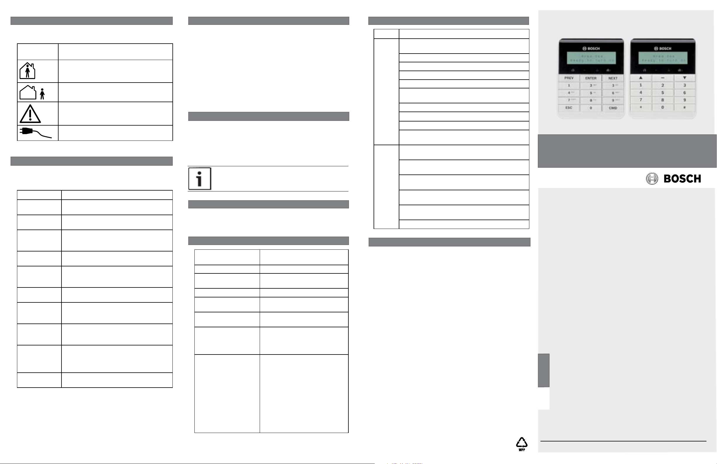
The B915 function keys are labeled in English. The B915I
function keys are labeled with icons.
The keypad display shows two-line system messages.
Users can adjust the keypad display brightness level, and they
can turn the keypad’s nightlight feature on or off.
Users can adjust keypad volume, and they can turn the key tone
(short tone emitted when a key is pressed) on or off.
1
R Y G B
PWR A B COM
ON DIP
3
1 2 3 4 5 6
2
COM Z1
2
1
Figure 2.1: Removing mounting plate from keypad
Callout ― Description
1 ― Retention clip
2 ― Mounting plate
2.2 | Set the keypad address
The keypads have 6 DIP switches that support SDI2
addresses 00 to 32. Use the switches to set the keypad
address per the control panel configuration.
If multiple SDI2 keypads reside on the same system, each
SDI2 keypad must have a unique address. Figure 2.2 shows
the address switch setting for address 01. Refer to Table 2.1
for keypad address settings for address 00 to 32.
ON DIP
After you set the address switches for the proper address,
follow the steps below to install the keypad.
CAUTION!
Remove all power (AC and battery) before making
any connections. Failure to do so might result in
personal injury and/or equipment damage.
3.1 | Mount the mounting plate
Mounting the mounting plate on the wall:
1. Use the mounting plate as a template to mark the wall
for mounting screw locations, a wire opening, and a level
line.
2. Use the supplied mounting hardware to mount the
mounting plate to the wall.
3. Pull the wiring through the wire opening.
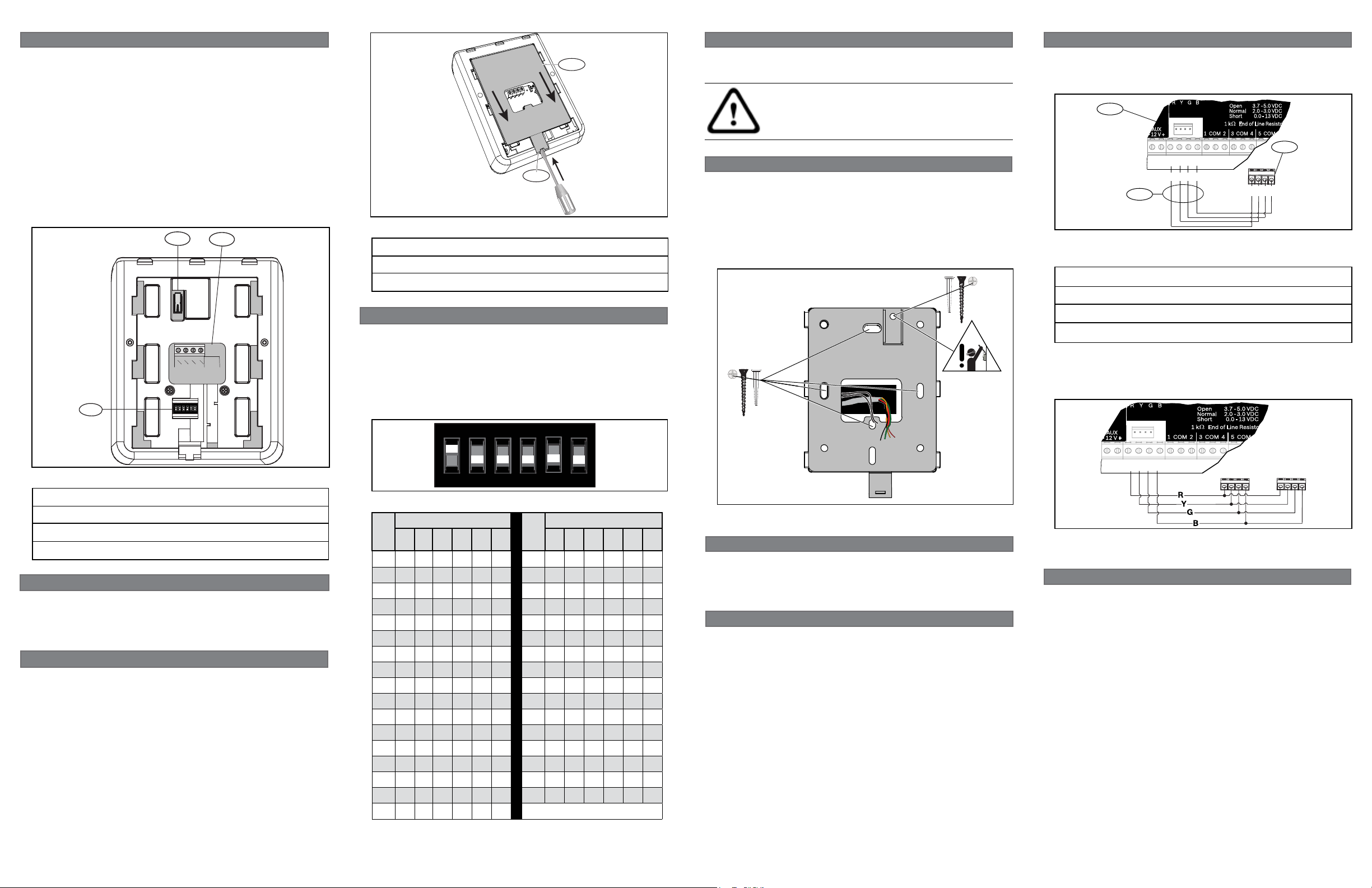
When you wire the keypad to a control panel, use the control
panel terminals labeled R, Y, G, B (PWR, A, B, COM). Refer to
Figure 3.2.
AUX
- 12 V +
R Y G B
PWR A B COM
R Y G B
1 COM 2 3 COM COM AUX R Y G B
1
2
3.7 - 5.0 VDC
Open
2.0 - 3.0 VDC
Normal
0.0 - 13 VDC
Short
1 k End of Line Resistors
3 COM 41 COM 2
5 COM 6
R Y G B
PWR A B COM
3
Figure 3.2: Wiring the keypad to the SDI2 bus connection
(B5512 control panel shown)
Callout ― Description
1 ― Control panel
2 ― Terminal wiring
3 ― Keypad’s wiring terminal block
You can connect keypads to the SDI2 data bus by parallel wire
run from the control panel to each keypad, wire from keypad to
keypad, or a combination of the two techniques.
Refer to Figure 3.3.
AUX
- 12 V +
R Y G B
3.7 - 5.0 VDC
Open
2.0 - 3.0 VDC
Normal
0.0 - 13 VDC
Short
1 k End of Line Resistors
3 COM 41 COM 2
5 COM 6
Figure 1.1: Keypad base overview
Callout ― Description
1 ― Tamper switch
2 ― SDI2 wiring terminal block
3 ― Address switches
2 | SDI2 address switches
Address switches determine the address for the keypad. The
control panel uses the address for communications. Use a
ballpoint pen to set the switches.
2.1 | Access the address switches
Removing the mounting plate from the back of the keypad:
1. Insert a slotted screwdriver under the retention clip to
release it. Do not pry upwards. Refer to Figure 2.1.
2. With your other hand, slide the mounting plate towards
the bottom of the keypad to unhook the mounting plate
from the keypad. Refer to Figure 2.1.
3. Remove the mounting plate.
1 2 3 4 5 6
Figure 2.2: Address switches
DIP Switches ON
1 2 3 4 5 6 1 2 3 4 5 6
SDI2
Address
SDI2
00 17 X X
01 X 18 X X
02 X 19 X X X
03 X X 20 X X
04 X 21 X X X
05 X X 22 X X X
06 X X 23 X X X X
07 X X X 24 X X
08 X 25 X X X
09 X X 26 X X X
10 X X 27 X X X X
11 X X X 28 X X X
12 X X 29 X X X X
13 X X X 30 X X X X
14 X X X 31 X X X X X
15 X X X X 32 X
16 X
DIP Switches ON
Address
Table 2.1: Address switch settings
Figure 3.1: Mounting the mounting plate
3.2 | Install the tamper screw
To provide tamper protection from prying the keypad from the
wall, optionally install a screw into the tamper location.
Refer to Figure 3.1.
3.3 | Wire the keypad
Prior to mounting the keypad on the mounting plate, connect
the wiring to the keypad terminals labeled R, Y, G, B. Refer to
Figure 3.2.
PWR A B COM
1 COM 23 COM COM AUX R Y G B
Figure 3.3: Installing multiple keypads using the
SDI2 terminals
3.5 | Mount the keypad
After wiring the keypad, mount it onto the mounting plate
by seating the mounting hook openings over the mounting
hooks and then sliding the keypad down.
Apply power to the system and test for proper operation.
4 | Status indicators
You can diagnose and troubleshoot the system using the
keypad’s status indicators. Refer to Table 4.1.
Status
Function
indicator
Green - Ready to turn Part On
Red - Part On (part armed)
Green - Ready to turn All On
Red - All On (all armed)
Yellow - System trouble
Blue - AC power present
Table 4.1: Keypad status indicators
5 | Audible tones
The keypad has a built-in sounder that produces several distinct
warning tones. The keypad backlight illuminates when it emits
an audible tone.
Tone Description
Fire signal When an area is in fire alarm, the keypad
emits a pulsed, high-pitched bell tone.
Gas signal When a gas point activates, the keypad
emits a unique high pitched tone.
User alarm When a user alarm (such as panic and
medical alarms) occurs, the tone sounds
for the programmed amount of time.
Burglary signal When an area is in alarm, the keypad
emits a steady, high pitched bell tone.
Entrance
warning
Exit warning The keypad emits an intermittent beep
Invalid button
buzz
Keypad
encoding tone
Trouble buzzer When a trouble event occurs, such as a
Watch tone A single clean tweedle tone alerts the
Table 5.1: Keypad audible tones
The keypad emits an intermittent beep
tone during entry delay periods to remind
the user to disarm the area.
tone during exit delay.
When an invalid button, or sequence of
buttons, is pressed, the keypad emits a
flat buzz tone.
The keypad emits a muted beep tone as
each button is pressed to indicate that
the entry was accepted.
service alert, the keypad emits a two-tone
warble until you enter a programmed
passcode with the appropriate authority.
user anytime a watch point is faulted.
6 | Supervision
The control panel supervises all keypads on the SDI2 bus.
If a supervised keypad fails to respond to the control panel,
the control panel declares a Missing Keypad Trouble. When
the control panel can again communicate with the keypad, it
restores the Missing Keypad Trouble.
During a Missing Keypad Trouble, any connected keypad that
maintained contact with the control panel shows the Missing
Keypad Trouble as its idle text, and shows the missing
keypad’s address. The communicating keypads also sound a
trouble tone. Users can silence the trouble tone. If no other
troubles exist, the tone silences when the missing keypad
restores.
7 | Show the firmware version
To show the keypad firmware version, r
restore power. The keypad shows the
address, and firmware version for 10 seconds.
You can momentarily remove power at the keypad (or at the
control panel by disconnecting and then reconnecting the
wire from the “R” terminal.
NOTICE!
You can also view a keypad’s firmware version in RPS.
emove and then
model number, keypad
8 | Keypad cleaning
Use a soft cloth and non-abrasive cleaning solution to clean your keypad
(for example, microfiber cloth and eyeglass cleaner). Spray the cleaner
onto the cloth. Do not spray cleaners directly onto the keypad.
9 | Specifications
Dimensions 5.5 in x 4.7 in x 1 in (139 mm x
118 mm x 23 mm)
Voltage (input) 12 VDC nominal
Current 35 mA in standby mode
70 mA in alarm mode
Operating temperature 0°C to +50°C (+32°F to +122°F)
Relative humidity 5% to 93% at +32°C (+90°F)
non-condensing
Terminal wire size 18 AWG to 22 AWG
(1.02 mm to 0.65 mm)
SDI2 wiring Maximum distance - wire size
(unshielded wire only):
984 ft (300 m) - 18 AWG to 22
AWG (1.02mm to 0.65 mm)
Compatibility B9512G/B9512G-E
B8512G/B8512G-E
B5512 version 2.03 and higher
B4512 version 2.03 and higher
B3512 version 2.03 and higher
D9412GV4 version 2.03 and
higher
D7412GV4 version 2.03 and
higher
(Refer to the control panel
installation document for the
number of supported devices.)
10 | Certifications
Region Certification
US UL 365 - Police Station Connected Burglar Alarm
Units and Systems
UL 609 - Local Burglar Alarm Units and Systems
UL 636 - Holdup Alarm Units and Systems
UL 985 - Household Fire Warning System Units
UL 1023 - Household Burglar-Alarm System Units
UL 1076 - Proprietary Burglar Alarm Units and
Systems
UL 1610 - Central Station Burglar Alarm Units
CSFM - California Office of The State Fire Marshal
FCC Part 15 Class B
CP-01-2010 - Control Panel Standard - Features
for False Alarm Reduction
CA Canada CAN/ULC S303 - Local Burglar Alarm
Units and Systems
CAN/ULC S304 - Signal Receiving Centre and
Premise Alarm Control Units
CAN/ULC S545 - Residential Fire Warning System
Control Units
ULC-ORD C1023 - Household Burglar Alarm
System Units
ULC-ORD C1076 - Proprietary Burglar Alarm
Units and Systems
ICES-003 - Digital Apparatus
Copyright
This document is the intellectual property of Bosch Security
Systems, Inc. and is protected by copyright. All rights reserved.
Trademarks
All hardware and software product names used in this
document are likely to be registered trademarks and must be
treated accordingly.
Bosch Security Systems, Inc. product manufacturing dates
Use the serial number located on the product label and refer to
the Bosch Security Systems, Inc. website at
http://www.boschsecurity.com/datecodes/.
Basic Keypad
B915/B915I
en Installation Guide
Bosch Security Systems, Inc.
130 Perinton Parkway
Fairport, NY 14450
USA
www.boschsecurity.com
Bosch Sicherheitssysteme GmbH
Robert-Bosch-Ring 5
85630 Grasbrunn
Germany
© 2015 Bosch Security Systems, Inc. F.01U.297.873 | 05 | 2015.09
 Loading...