

Bosch B901 Installation Manual
1 | Overview
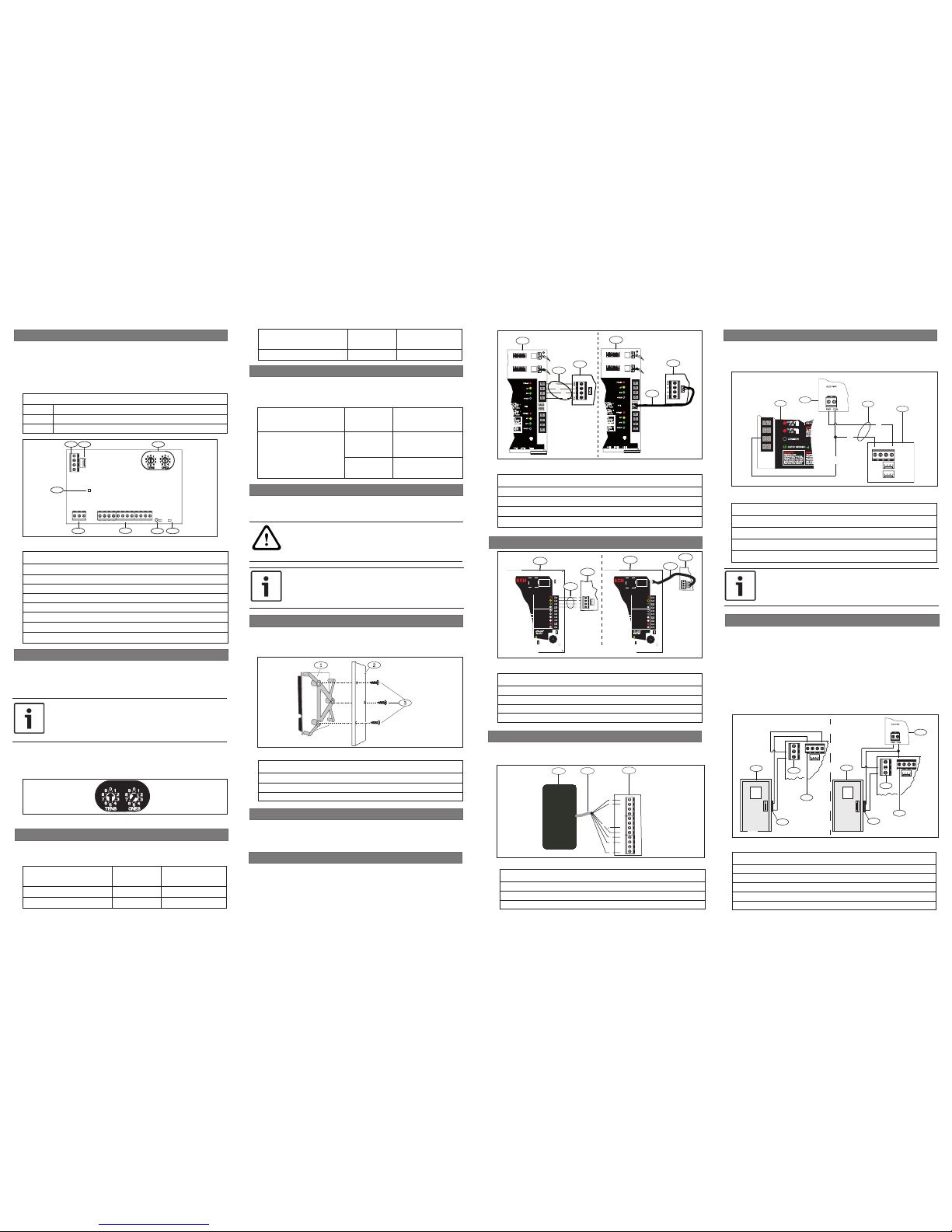
3.4 | Wire to the SDI control panel
Callout ― Description
1 ― Bosch control panel (GV3 shown)
2 ― Terminal wiring
3 ― B901 Access Control Module
4 ― Interconnect cable (P/N: F01U79745) (included)
Figure 3.3: SDI wiring from control panel to B901
2.2 | Valid addresses for SDI
Valid B901 addresses are dependant on the number of modules allowed
and the desired failure mode (Fail Safe, Fail Secure) by a particular
control panel.
SDI2
RESETZONEX
TAMPER
SDI2
PWR+/R
A/Y
B/G
COM/B
PWR+/R
A/Y
B/G
COM/B
24
25
26
27
28
29
23
26
WARNING!
Multi-Battery
installation requires
Dual Battery rnes
I r
ir r
Ba
tteryR
er t year t
one or t
tterie
BatteryR
er t year t
one or t
tterie
BatteryR
er t year t
one or t
tterie
3
2
SDI2
RESETZONEX
TAMPER
SDI2
PWR+/R
A/Y
B/G
COM/B
PWR+/R
A/Y
B/G
COM/B
24
25
26
27
28
29
23
26
WARNING!
Multi-Battery
installation requires
Dual Battery rnes
I r
ir r
Ba
tteryR
er t year t
one or t
tterie
BatteryR
er t year t
one or t
tterie
BatteryR
er t year t
one or t
tterie
3
4
1
1
B
G
Y
R
Callout ― Description
1 ― Bosch control panel (B9512G shown)
2 ― Terminal wiring
3 ― B901 Access Control Module
4 ― Interconnect cable (P/N: F01U79745) (included)
Figure 3.2: SDI2 wiring from control panel to B901
R
Y
G
B
R
Y
G
B
R
Y
G
B
Commercial Protected-Premises Control Panel
D9412GV3 Control Panel is UL Listed For
Central Station, Remote Station, Local,
Auxiliary,
Proprietary, and Household Fire Alarm, and
VOLTAGE RANGES
Open 3.7 - 5.0 VDC Short 0.0 - 1.3 VDC
Normal 2.0 - 3.0 VDC
Reset Pin
Disable all except Battery
Charging and Programming
PERIPHERAL DEVICE CONNECTIONS
RED
POWER +
YELLOW
DATA BUS A
GREEN
DATA BUS B
BLACK
COMMON
ZONEX OUT 1
ZONEX IN 1
NFPA
Style 4.0
Signaling
Line
Circuits
D9412GV3
26
25
ZONEX POWER +
24
ZONEX COMMON
23
SDI Connector
ZONEX OUT 2
ZONEX IN 2
Battery: Replace every 3 to
5 years with one or two Model
D126 or D1218 12 V Lead Acid
Batteries.
Operation Monitor LED
Pulses when Normal
Flickers when Ringing
GREEN
Point 8, S3 Option
25
Point 4
16
Point 5
Point 6
17 19
Point 7
Point 8
21
20
22
Minimum system reuirements or Classiication in accordance with
ANSISIA CP-01-2007:
UL Listed and Classiied control unit Model D9412GV3, D7412GV3, or
D7212GV3
UL Listed and Classiied keypad Model D1256, D1257, D1260, D1255,
D1255R, or D1255RW
WARNING
To prevent risk o
electric shock,
disconnect AC
power and
telephone lines
beore servicing.
1815
Not suitable or remote station protected premises
services where separate transmission circuits
1
1
3
3
2
4
3 | Installation
After you set the address switch for the proper address, install the
module in the enclosure, and then wire it to the control panel.
CAUTION!
Remove all power (AC and battery) before making any
connections. Failure to do so might result in personal
injury and/or equipment damage.
3.1 | Mount the module in the enclosure
Mount the module into the enclosure’s 3-hole mounting pattern using
the supplied mounting screws and mounting bracket.
Refer to Figure 3.1.
Figure 3.1: Mounting the module in the enclosure
Callout ― Description
1 ― Module with mounting bracket installed
2 ― Enclosure
3 ― Mounting screws (3)
4
2
PWR A B COM
B
3
1
B
RELAY C
EARTH GROUND
COMMON
10
9
8
7
WARNING!
Multi-Battery
installation requires
Model D122 or D122L
Dual Battery Harness.
Improper installation
can be a fire hazard
.
W
equipment.
any output must be
supervised.
The syst
contr
DAC, OT, N
This eq
Alar
W
servicing.
OUTPUT
B (2)
OUTPUT
C (3)
R
Callout ― Description
1 ― Control panel COM terminal (B9512G shown)
2 ― 12 VDC regulated power-limited power supply (B520 shown)
3 ― Terminal wiring (PWR and COM terminal wiring)
4 ― B901 Access Control Module
Figure 3.5: Wiring the card reader to the B901
3.6 | Wire to 12VDC power supply (optional)
Refer to Figure 3.5 to wire additional power to a regulated powerlimited power supply for fire protective signaling units and commercial/
residential burglar units.
Control panel Valid B901
addresses
Designation
B9512G/B9512G-E/
B8512G/B8512G-E
D9412GV4/D7412GV4
D9412GV3/D7412GV3
D9412GV2/D7412GV2,
D9000
81 - 88 Devices 1 - 8
Fail Safe mode =
door unlocked
91-98 Devices 1 - 8 Fail Se-
cure = door locked
3.5 | Wire to the card reader
Use the terminals labeled LED, DATA1, DATA0, 5.2V or 12V, COM, and T+
when wiring the module to a card reader. Refer to Figure 3.4.
3.2 | Mount the access card reader
Refer to your access card reader installation instructions for proper
installation and maintenance procedures related to your supported
card reader.
2.1 | Valid addresses for SDI2
Valid B901 addresses are dependant on the number of modules allowed
by a particular control panel.
Control panel Valid B901
addresses
Designation
B9512G/B9512G-E 01 - 32 Devices 1 - 32
B8512G/B8512G-E 01 - 08 Devices 1 - 8
3.3 | Wire to the SDI2 control panel
When you wire the module to a control panel, use the control panel
terminals labeled R, Y, G, B (PWR, A, B, COM). Connect them to the
module terminals labeled R, Y, G, B (PWR, A, B, COM). Use either
terminal strip wiring or interconnect wiring connector to the control
panel. Do not use both. Refer to Figures 3.2 - 3.3.
W
Br
G
B
P
T+ COM ZN+ RTE
COM REX 12V 5.2V
2
1
3
DATA DATA BUZZ LED
0 1
R
Callout ― Description
1 ― Card reader (ARD-AYK12 shown)
2 ― Terminal wiring
3 ― B901 Access Control Module
Figure 3.4: Wiring the card reader to the B901
DOOR
NC C N0
PWR A B COM
1
5
2
3
DOOR
NC C N0
PWR A B COM
1
5
2
4
3
Callout ― Description
1 ― Door
2 ― B901 door lock relay terminal
3 ― B901 terminal
4 ― AUX PWR terminal (12 VDC) (B520 shown)
5 ― Door strike (12 VDC)
Figure 3.6: Wiring the door strike to the B901
Compatible Credential Formats
37 bit HID H10304 (With Site Code)
37 bit HID H10302 (No Site Code)
26 bit HID H10301 EM-EM4200 (3-byte or 5-byte)
Control panel Valid B901
addresses
Designation
B6512 01 - 04 Devices 1 - 4
2 | Address settings
Two address switches determine the address for the B901
Access Control Module. The control panel uses the address for
communications. The address also determines the output numbers. Use
a slotted screwdriver to set the two address switches.
NOTICE!
The module reads the address switch setting only during
power up. If you change the switches after you apply power to
the module, you must cycle the power to the module in order
for the new setting to be enabled.
Set the address switches per the control panel configuration. If
multiple B901 modules reside on the same system, each B901 module
must have a unique address. Figure 2.1 shows the address switch
settings for address 01.
Figure 2.1: Address switches
NOTICE!
Use only Access Control listed power supplies for powering
door strikes.
NOTICE!
B901 tamper generates an SDI - “Missing Door” or an
SDI2 - “Module Tamper” message (if Enclosure Tamper
parameter is set to Yes).
3.7 | Wire to the door strike
A relay provides a dry contact single pull double throw output. Some
strikes require a closed circuit to unlock the door, while others require
an open circuit to unlock the door.
• Common (C). For 12/24 VDC strikes, provide input power here
from the power supply. Refer to Figure 3.6.
• Normally closed (NC). For door strikes that require an interruption
of power to open. Connect the positive side of the door strike to
the NC terminal. Refer to Figure 3.6.
• Normally open (NO). For door strikes that require power to open.
Connect the positive side of the door strike to the NO terminal.
Refer to Figure 3.6.
The B901 Access Control module is a fully supervised SDI2/SDI
device that allows access control integration for compatible control
panels. Each module can store up to 2000 user tokens (on SDI2),
each with a different access level for each door. Authority for access
is controlled by the user’s authority level, the time of day, the state
of the door, and the armed state to the module.
READER
T+ COM ZN+ RTE COM REX 12V 5.2V DATA0 DATA1 BUZZER LEDNC C N0
PWR A B COM
2
3
4
5
RELAY
1
6
7
8
Figure 1.1: Access control module
Callout ― Description
1 ― Terminal connector
2 ― Interconnect wiring connectors
3 ― Address switch
4 ― Reader LED
5 ― Heartbeat LED (blue)
6 ― Reader and door terminals
7 ― Relay terminals
8 ― Relay LED
Bosch Security Systems, Inc.
130 Perinton Parkway
Fairport, NY 14450
USA
www.boschsecurity.com
© 2017 Bosch Security Systems, Inc. F.01U.300.416 | 10 | 2017.01
Bosch Sicherheitssysteme GmbH
Robert-Bosch-Ring 5
85630 Grasbrunn
Germany
Copyright
This document is the intellectual property of Bosch Security Systems, Inc. and
is protected by copyright. All rights reserved.
Trademarks
All hardware and software product names used in this document are likely to be
registered trademarks and must be treated accordingly.
Bosch Security Systems, Inc. product manufacturing dates
Use the serial number located on the product label and refer to the
Bosch Security Systems, Inc. website at
http://www.boschsecurity.com/datecodes/.
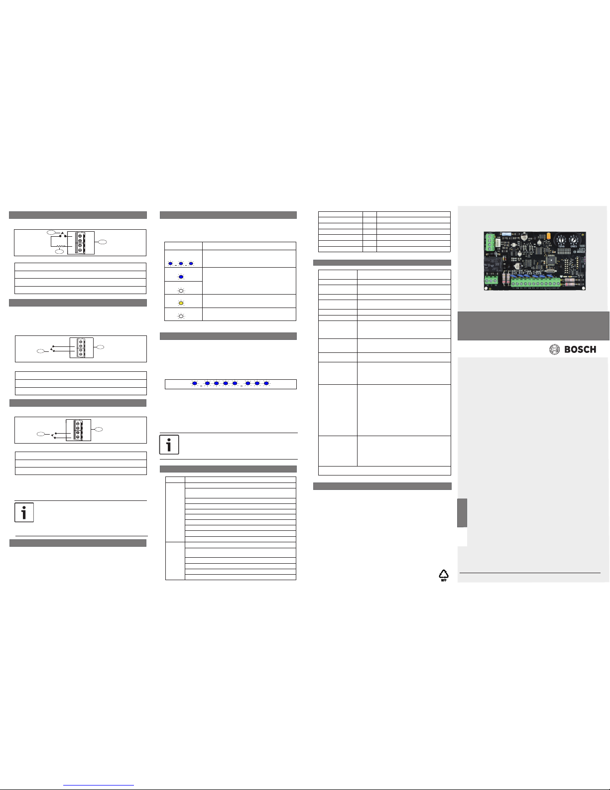
8 | Specifications
Dimensions 2.9 in x 5.0 in x 0.6 in (73.5 mm x 127 mm x 15.25
mm)
Voltage (input) 12 VDC nominal
Current Standby: 110 mA + reader current
Alarm: 110 mA + reader current
Alarm output Form C relay (NC, COM, NO) at 12/24 V @ 2.0 A
Operating
temperature
0°C to +50°C (+32°F to +122°F)
Relative humidity 5% to 93% at +32°C (+90°F) non-condensing
Terminal wire size 18 AWG to 22 AWG (1.02 mm to 0.65 mm)
SDI2/SDI wiring
to B901 + Reader
with external power
supply
Maximum distance - wire size (unshielded wire only):
1000 ft (305 m) - 22 AWG (0.65 mm), 2500 ft (762 m)
- 18 AWG (1.02 mm)
SDI2/SDI wiring to
B901 + Reader from
control panel
175 ft (53 m) - 22 AWG (0.65 mm), 450 ft (137 m) 18 AWG (1.02 mm)
Wiring distance from
B901 to Reader
200 ft (61 m) - 22 AWG (0.65 mm), 500 ft (152 m) 18 AWG (1.02 mm) Reader dependant
Bosch compatible
control panels
B9512G/B9512G-E/B8512G/B8512G-E/B6512/
D9412GV4/D7412GV4/D9412GV3/D7412GV3/
D9412GV2/D7412GV2/D9412G/D7412G
(Refer to the control panel installation document for
the number of supported devices.)
Bosch compatible
readers and
accessories
ARD-AYH12 EM Prox Wall Mount
ARD-AYJ12 EM Prox Mullion
ARD-AYK12 EM Prox Mini Mullion
ARD-AYQ12 EM Prox Wall Mount Vandal Resistant
ARD-AYCE65B EM Prox or PIN Mullion
ARD-R10 HID iClass Mini Mullion
ARD-R40 HID iClass Wall Mount
D8223 HID Prox Wall Mount
D8224 HID Prox Mullion
D8224-SP HID Prox Switch Plate Mount
D8225 HID Prox Mini Mullion
D8229 PIN Reader
Bosch compatible
credentials
ACA-ATR13 EM Tokens*
ACD-ATR11ISO EM Cards*
ACD-ATR14CS EM Clamshell Cards
ACD-IC2K26-50 iClass Cards**
ACT-IC2K26-10 iClass Tokens**
D8236-10 HID Prox Cards***
D8236KF-10 HID Prox Tokens***
* EM cards work with EM readers, ** iClass cards work with iClass readers,
*** Prox cards work with Prox readers
Approved For Level Comment
Destructive Attack I
Line Security IV IP or cellular with encryption
Line Security II IP or cellular without encryption
Line Security I B430/PSTN
Endurance IV
Send by Power IV
7 | Certifications
Region Certification
USA UL 294 - Access Control System Units
UL 365 - Police Station Connected Burglar Alarm Units and
Systems
UL 609 - Local Burglar Alarm Units and Systems
UL 864 - Control Units and Accessories for Fire Alarm Systems
UL 985 - Household Fire Warning System Units
UL 1023 - Household Burglar-Alarm System Units
UL 1076 - Proprietary Burglar Alarm Units and Systems
UL 1610 - Central Station Burglar Alarm Units
CSFM - California Office of The State Fire Marshal
FCC Part 15 Class B
CA Canada CAN/ULC S303 - Local Burglar Alarm Units and Systems
CAN/ULC S304 - Signal Receiving Centre and Premise Alarm
Control Units
ULC-ORD C1023 - Household Burglar Alarm System Units
ULC-ORD C1076 - Proprietary Burglar Alarm Units and Systems
ULC 2016701-S1871E - Fire Alarm and Security Subassemblies
ICES-003 - Information Technology Equipment (ITE)
When the tamper switch is activated, the heartbeat LED stays OFF
for 3 sec before indicating the firmware version. The LED pulses the
major, minor, and micro digits of the firmware version, with a 1 sec
pause after each digit.
In the following example, the version 1.4.3 shows as LED flashes:
[3 sec pause] *___****___*** [3 sec pause, then normal operation].
To show the firmware version using an LED flash pattern:
- If the optional tamper switch is installed:
With the enclosure door open, activate the tamper switch (push and
release the switch).
- If the optional tamper switch is NOT installed: Momentarily short
the T+ terminal.
Refer to Figure 6.1 for an example of flash patterns.
6 | Show the firmware version
Figure 6.1: Firmware LED flash patterns
5 | LED descriptions
The module includes one blue Heartbeat LED, and one Reader
LED. The Heartbeat LED indicates that the module has power as
well as a module’s current state. The Reader LED indicates data
transmission. Refer to Table 5.1.
Flash Pattern
Function
Flashes once
every 1 sec
Normal state: Indicates normal operation
state. (blue)
ON Steady LED trouble state: Module is not powered
(for OFF Steady only), or some other
trouble condition prohibits the module from
communicating with the control panel.
OFF Steady
Flashes rapidly Card data is executing (yellow)
OFF Steady No card data is being received
Table 5.1: LED descriptions
4 | Configuration
3.8 | Wire to door contact
ZN+ RTE
COM REX
2
1
Callout ― Description
1 ― RTE device
2 ― B901 Access Control Module
Figure 3.7: Wiring the door contact
ZN+ RTE
COM REX
3
1
2
Callout ― Description
1 ― Door Contact
2 ― 1k EOL
3 ― B901 Access Control Module
Figure 3.8: Wiring the RTE
NOTICE!
Firmware reprogramming on the B901 is not supported if
connected via the SDI bus. Updating the firmware is achieved
via the SDI2 connection only.
Wire the door contact.
3.8.1 | Request to Enter (RTE)
Wire the Request to Enter (RTE) device. The strike is activated, and
the door point is shunted when RTE is momentarily shorted to COM.
The Shunt only option shunts the point when this input is momentarily
shorted. To activate the shunt but not the strike, program RTE Shunt
Only? as [YES].
3.8.2 | Request to Exit (REX)
After you wire the module, power up the system and configure the B901
using Remote Programming Software (RPS) to assign the module to
an assigned area. Whenever possible, be consistent when numbering
doors, areas, and keypads. For example, assign Door 1 to Area 1 and
keypad 1. Test for proper operation.
Figure 3.9: Wiring the REX
ZN+ RTE
COM REX
1
2
Callout ― Description
1 ― REX device
2 ― B901 Access Control Module
Wire the Request to Exit (REX) device.
The strike is activated, and the door point is shunted when REX is
momentarily shorted to COM. The Shunt only option shunts the point
when this input is momentarily shorted. To activate the shunt but not
the strike, program REX Shunt Only? as [YES].
NOTICE!
Do not use a Request to Exit device (REX) for emergency
exit applications. NFPA 101 requires that a UL Listed panic
device be used to provide direct power from the standby
power source. Check with your local Authority Having
Jurisdiction (AHJ) prior to installing your system.
en Installation Guide
Access Control Interface Module
B901
 Loading...