

Bosch B9512G-E, B8512G-E, B8512G Installation Manual
Control Panels
B9512G/B8512G (B9512G‑E/B8512G‑E)
en
Installation Manual


Control Panels Table of contents | en 3
Bosch Security Systems, Inc. Installation Manual 2018.07 | 10 | F.01U.303.996
Table of contents
1
Certifications, approvals, listings, and safety 9
1.1 Listings and approvals 9
1.1.1 UL 9
1.1.2 ULC 9
1.1.3 Security Industry Association (SIA) 9
1.1.4 Department of Defense (DoD) 9
1.1.5 Department of Energy 9
1.1.6 National Institute of Standards and Technology (NIST) 9
1.1.7 Federal Communications Commission (FCC) Rules 10
1.1.8 Industry Canada (IC) 10
1.1.9 CE 10
1.2 Safety 11
1.2.1 Lightning 11
1.2.2 Earth ground 11
1.2.3 Power 12
2
Introduction 13
2.1 About documentation 13
2.1.1 Related documentation 13
2.2 Bosch Security Systems, Inc. product manufacturing dates 15
3
System overview 16
3.1 Parts list 16
3.2 Control panel capacities 16
3.3 Features 17
3.3.1 SDI2 interconnect wiring 17
3.3.2 Points 17
3.3.3 Areas and accounts 17
3.3.4 Digital communication 18
3.3.5 Keypads 18
3.3.6 Events 18
3.3.7 Programming 19
3.3.8 Firmware updates 19
3.3.9 Access control 19
3.3.10 Ground fault detection 19
3.3.11 Dual authentication 19
3.3.12 Recent closing 20
3.4 Accessories 20
3.4.1 Compatible UL Listed Synchronization (Sync) modules and strobes 25
4
Installation checklist 30
5
Control panel installation 31
5.1 Installing the enclosure 31
5.2 Installing the control panel 31
5.2.1 Earth ground 32
5.2.2 Ground Fault Detect enable 32
5.2.3 Ground fault detection troubleshooting 32
5.3 Control panel to module wiring overview 33
6
Power supply 36
6.1 Secondary (DC) power 36
6.1.1 Install the battery 36

4 en | Table of contents Control Panels
2018.07 | 10 | F.01U.303.996 Installation Manual Bosch Security Systems, Inc.
6.1.2 BATTERY STATUS LED 37
6.1.3 Battery maintenance 38
6.1.4 Battery supervision 38
6.1.5 Battery charging circuit float charge 38
6.1.6 Battery discharge and recharge schedule 39
6.2 B520 aux power supply 39
6.2.1 SDI2 address settings 40
6.2.2 Supervision 40
6.2.3 Auxiliary power supply trouble conditions 40
6.2.4 Installation and control panel wiring (B520) 40
6.2.5 Powered device and battery wiring 41
7
Telephone communications 44
7.1 B430 Plug-in Communicator, Telephone 44
7.1.1 Supervision 44
7.1.2 Installation and module wiring (B430) 44
7.1.3 Diagnostic LEDs 45
7.2 Phone jack location 45
7.3 Telephone line monitor 46
7.4 Called party disconnect 46
7.5 Communication failure 47
8
IP communications 48
8.1 On-board Ethernet connection 48
8.1.1 Supervision 48
8.1.2 Local programming 48
8.1.3 On-board Ethernet diagnostic LEDs 49
8.2 Conettix Plug-in cellular modules 50
8.3 B426 Ethernet Communication Module 50
8.3.1 Address and emulation settings 50
8.3.2 Supervision 50
8.3.3 B426 module faults 51
8.3.4 Installation and control panel wiring (B426) 51
8.3.5 Diagnostic LEDs 52
8.3.6 Local programming 53
8.4 B450 Conettix plug-in communicator interface 54
8.4.1 SDI2 address settings 54
8.4.2 Supervision 54
8.4.3 Installation and control panel wiring (B450) 54
8.4.4 Diagnostic LEDs 55
8.5 Compatible receivers for IP communication 56
9
Keypads, keyswitches, keyfobs and transmitters 58
9.1 Keypads 58
9.1.1 Keypads overview 58
9.1.2 B921C Two-line Capacitive Keypad with Inputs 59
9.1.3 Shortcuts and custom functions 59
9.1.4 Address settings 60
9.1.5 Supervision 60
9.1.6 Installation and control panel wiring (keypads) 60
9.1.7 Sensor loops overview and wiring (B921C/B942/B942W only) 61
9.1.8 Output wiring (B942/B942W only) 62

Control Panels Table of contents | en 5
Bosch Security Systems, Inc. Installation Manual 2018.07 | 10 | F.01U.303.996
9.1.9 Troubleshooting 62
9.2 Keyswitches 62
9.2.1 Operation 63
9.2.2 Installation and control panel wiring (keyswitches) 63
9.3 RADION keyfobs and Inovonics pendant transmitters 64
10
On-board outputs 65
10.1 Circuit protection 65
10.2 Total available power 65
10.3 Continuous power outputs 66
10.4 Programmable power outputs 66
10.4.1 Terminals 6 and 7 66
10.4.2 Terminal 8 67
10.5 USB power 67
11
Off-board outputs 68
11.1 B308 octo-output module 68
11.1.1 SDI2 address settings 68
11.1.2 Supervision 68
11.1.3 Installation and control panel wiring (B308) 69
11.2 B600 Retrofit ZONEX Module 69
11.2.1 Installation and control panel wiring (B600) 70
11.2.2 D8129 Octo-relay Module 71
12
On-board points 72
12.1 Point sensor loops 72
12.1.1 Single EOL (and no EOL) resistor circuit style 72
12.1.2 Dual EOL resistor circuit style 73
12.2 Point response time 74
13
Off-board points 75
13.1 B208 octo-input module 75
13.1.1 SDI2 address settings 75
13.1.2 Supervision 75
13.1.3 Installation and control panel wiring (B208) 75
13.1.4 Sensor loops overview and wiring 77
13.2 B299 POPEX Module 79
13.2.1 SDI2 address settings 79
13.2.2 Supervision 79
13.2.3 Installation and control panel wiring (B299) 80
13.2.4 POPIT devices overview and wiring 80
13.3 B600 Retrofit ZONEX Module 81
13.3.1 Installation and control panel wiring (B600) 81
13.3.2 D8125 expansion 82
13.3.3 D8128D OctoPOPIT Eight-point Expander 83
13.4 Off-board points test 84
13.5 Extra Point events 84
13.6 Missing point conditions 84
14
Wireless modules 85
14.1 B810 receiver 85
14.1.1 SDI2 address settings 85
14.1.2 Supervision 85
14.1.3 Installation and control panel wiring (B810) 85

6 en | Table of contents Control Panels
2018.07 | 10 | F.01U.303.996 Installation Manual Bosch Security Systems, Inc.
14.2 B820 SDI2 Inovonics Interface Module 86
14.2.1 SDI2 address settings 86
14.2.2 Supervision 86
14.2.3 Installation and control panel wiring (B820) 86
15
Access control 88
15.1 B901 door controller 88
15.1.1 Address settings 88
15.1.2 Supervision 88
15.1.3 Installation and control panel wiring (B901) 89
15.2 D9210C access control interface module 89
15.3 Card reader wiring 90
16
Program and test the control panel 91
16.1 Program the control panel 91
16.1.1 Program the control panel with RPS 91
16.1.2 Program the control panel with the Installer Services Portal programming tool 92
16.1.3 Program the control panel with a keypad 92
16.2 Walk tests 92
16.2.1 Fire walk test 92
16.2.2 Intrusion walk test 93
16.2.3 Service walk test 93
16.2.4 Invisible walk test 94
17
Control panel board overview 95
18
System wiring diagrams 97
18.1 Power supply side wiring 98
18.2 Input points wiring with D125B, D130, or D129 99
18.3 Input points wiring with or without EOL resistors 99
18.4 SDI and ZONEX wiring 100
18.5 SDI2 devices general system wiring 102
18.5.1 SDI2 bus wiring recommendations 102
18.6 2-wire smoke wiring (D125B) 104
19
Approved applications 106
19.1 Optional compatible equipment 106
19.1.1 Burglar applications 106
19.1.2 Bank safe and vault applications 106
19.1.3 Fire applications 109
19.1.4 Enclosures 111
19.2 Combination fire and intrusion alarm systems 111
19.3 Compatible UL listed components 111
19.4 Standby battery requirements and calculations 114
19.4.1 Household Fire Warning equipment 117
19.5 UL 365 - Police Station Connected Burglar Alarm Units and Systems 118
19.6 UL 636 - Holdup Alarm Units and System 118
19.7 Required programming to meet UL 864 118
19.8 Required values to achieve 180s (ULC)/200s (UL) supervision interval 122
19.9 ULC 122
20
Keypad Installer menu 123
20.1 [1] Program menu (Programming) 130
20.1.1 [1] Reporting > [1] Phone menu parameters 130
20.1.2 [1] Reporting > [2] Network menu parameters 131

Control Panels Table of contents | en 7
Bosch Security Systems, Inc. Installation Manual 2018.07 | 10 | F.01U.303.996
20.1.3 [1] Reporting > [3] Routing menu parameters 132
20.1.4 [1] Reporting > [4] Personal Note menu parameters 133
20.1.5 [2] Network > [1] Ethernet > (choose the bus module or on-board) > [1] Module
Parameters menu
135
20.1.6 [2] Network > [1] Ethernet > (choose the bus module or on-board) > [2] Address
Parameters menu
136
20.1.7 [2] Network > [1] Ethernet > (choose the bus module or on-board) > [3] DNS
Parameters menu
137
20.1.8 [2] Network > [2] Cellular > (choose the SDI2 cellular module or plug-in module) 137
20.1.9 [3] RPS > [1] RPS Passcode menu parameters 138
20.1.10 [3] RPS > [2] RPS Phone Number menu parameters 139
20.1.11 [3] RPS > [3] RPS IP Address menu parameters 139
20.1.12 [3] RPS > [4] RPS Port Number menu parameters 139
20.1.13 [4] Area Options menu parameters 140
20.1.14 [5] Keypad menu parameters 141
20.1.15 [6] Users menu parameters 144
20.1.16 [7] Points menu parameters 144
20.1.17 [8] Disable Programming menu 152
20.2 [2] Wireless menu 152
20.2.1 [1] RF Point Menu> [1] Enroll Point RFID 152
20.2.2 [1] RF Point Menu> [2] Replace Point RFID 153
20.2.3 [1] RF Point Menu> [3] Remove Point RFID 153
20.2.4 [2] RF Repeater Menu > [1] Add Repeater 153
20.2.5 [2] RF Repeater Menu > [2] Replace Repeater 154
20.2.6 [2] RF Repeater Menu > [3] Remove Repeater 154
20.2.7 [3] RF Diagnostic Menu > [1] RF Points 154
20.2.8 [3] RF Diagnostic Menu > [2] RF Repeater Menu 155
20.3 [3] Diags menu 155
20.3.1 [1] Wireless 155
20.3.2 [2] Network menu 155
20.3.3 [3] Cellular menu 156
20.3.4 [4] IP Camera 156
20.3.5 [5] Cloud 156
20.4 [4] Service Bypass (Serv Byp) menu 157
20.5 [5] Versions menu 157
20.6 [6] Cloud menu 158
20.7 [7] USB Power 158
21
Specifications 159
21.1 Wire requirements 160
22
Appendix 163
22.1 Address settings 163
22.1.1 B208 address settings 163
22.1.2 B299 address settings 165
22.1.3 B308 address settings 165
22.1.4 D8128D address settings 167
22.1.5 D8129 address settings 168
22.1.6 B901 address settings 168
22.1.7 B91x address settings 168
22.1.8 D9210C address settings 169

8 en | Table of contents Control Panels
2018.07 | 10 | F.01U.303.996 Installation Manual Bosch Security Systems, Inc.
22.1.9 SDI keypad address settings 170
22.2 Reporting and device number information 171
22.2.1 Report format definitions 171
22.2.2 Device numbers (zzz, dddd) 180
22.2.3 Communication Trouble device numbers (zzzz) 181
22.2.4 Special User IDs (uuuu, iiii) 181
22.2.5 Keypad alarm virtual point numbers (ppp, pppp) 182
22.3 AutoIP 182

Control Panels Certifications, approvals, listings, and safety | en 9
Bosch Security Systems, Inc. Installation Manual 2018.07 | 10 | F.01U.303.996
1 Certifications, approvals, listings, and safety
This section provides certification and approval listings and safety information.
1.1 Listings and approvals
This document includes the section Approved applications, page 106. Refer to this section for
guidelines on installing the control panels in Underwriters Laboratories Inc. (UL) and firespecific applications.
1.1.1 UL
Listed for:
– UL 365 - Police Station Connected Burglar Alarm Units and Systems
– UL 609 - Local Burglar Alarm Units and Systems
– UL 636 - Holdup Alarm Units and Systems
– UL 864 - Control Units and Accessories for Fire Alarm Systems (Commercial Fire)
– UL 985 - Household Fire Warning System Units
– UL 1023 - Household Burglar Alarm System Units
– UL 1076 - Proprietary Burglar Alarm Units and Systems
– UL 1610 - Central Station Burglar Alarm Units
– UL 1635 - Digital Alarm Communicator System Units
1.1.2 ULC
Listed for:
– ULC C1023 - Household Burglar Alarm System Units
– ULC C1076 - Proprietary Burglar Alarm Units and System
– ULC S303 - Local Burglar Alarm Units and System
– ULC S304 - Central and Monitoring Station Burglar Alarm Units
– ULC S545 - Residential Fire Warning System Control Units
– ULC S559 – Fire Signal Receiving Centres and Systems
1.1.3 Security Industry Association (SIA)
Listed for Control Panel Standard - Features for False Alarm Reduction ANSI/SIA CP-01-2010.
1.1.4 Department of Defense (DoD)
The B9512G/B8512G control panels were granted approval for Department of Defense (DoD)
installations in Sensitive Compartmented Information Facilities (SCIF).
1.1.5 Department of Energy
This control panel operates on a transformer that has been reviewed by a third party and
deemed to be compliant to the Department of Energy, U.S. Energy Conservation Standard for
External Power Supplies (found in section 10 CFR 430.32(w)(1)(i) of the Federal Code) as an
indirect device.
1.1.6 National Institute of Standards and Technology (NIST)
When communicating via a network, listed for Advanced Encryption Standard (AES), Federal
Information Processing Standards Publication 197 (FIPS 197).

10 en | Certifications, approvals, listings, and safety Control Panels
2018.07 | 10 | F.01U.303.996 Installation Manual Bosch Security Systems, Inc.
1.1.7 Federal Communications Commission (FCC) Rules
Part 15
This equipment was tested and found to comply with the limits for a Class B digital device,
pursuant to Part 15 of the FCC rules. These limits are designed to provide reasonable
protection against harmful interference when the equipment is operated in a commercial
environment.
This equipment generates, uses, and can radiate radio frequency energy; and if not installed
and used according to the instructions, can cause harmful interference to radio
communications.
Operation of this equipment in a residential area is likely to cause harmful interference, in
which case the user is required to correct the interference at his or her own expense.
Part 68
The B430 module by Bosch Security Systems, Inc. is registered with the Federal
Communication Commission (FCC) under Part 68, for connection to the public telephone
system using an RJ31X or RJ38X phone line connection jack installed by the local telephone
company.
Do not connect registered equipment to party lines or coin-operated telephones. Notify the
local telephone company and provide the following information before connecting the control
panel to the telephone network:
– The particular line to which you connect the module
– Make (Bosch Security Systems, Inc.), model (B9512G/B8512G), and serial number of the
control panel
– FCC registration number: ESVAL00BB430
– Ringer eq: 0.0B
1.1.8 Industry Canada (IC)
ICES-003 - Information Technology Equipment
This Class B digital equipment meets all requirements of the Canadian interference-causing
equipment regulations.
Cet appareil numérique de la Class A respecte toutes les exifences de règlement sue le
matériel brouilleur du Canada.
CS-03 - Compliance Specification for Terminal Equipment
The B430 module by Bosch Security Systems, Inc. meets the applicable Industry Canada
technical specifications. The Ringer Equivalence Number (REN) is an indication of the
maximum number of devices allowed to be connected to a telephone interface. The
termination of an interface may consist of any combination of devices subject only to the
requirement that the sum of the RENs of all the devices not exceed five.
Le présent matériel est conforme aux spécifications techniques applicables d'Industrie
Canada.
L'indice d'équivalence de la sonnerie (IES) sert à indiquer le nombre maximal de terminaux qui
peuvent être raccordés à une interface téléphonique. La terminaison d'une interface peut
consister en une combinaison quelconque de dispositifs, à la seule condition que la somme
d'indices d'équivalence de la sonnerie de tous les dispositifs n'excède pas cinq.
1.1.9 CE
Listed for:
– EMC
– LVD
– RoHS
Control Panels Certifications, approvals, listings, and safety | en 11
Bosch Security Systems, Inc. Installation Manual 2018.07 | 10 | F.01U.303.996
1.2 Safety
Notice!
After system installation and any control panel programming, perform a complete system test
(a UL 864 requirement). A complete system test includes testing the control panel, all
devices, and communication destinations for proper operation.
1.2.1 Lightning
The control panel design significantly reduces the adverse effects of lightning. Take
installation precautions to further reduce these adverse effects.
Effects of lightning
Electronics involved in a direct lightning strike or near a lightning strike can show adverse
effects. When lightning strikes, several things happen:
– An electromagnetic wave spreads from the center point of the strike inducing high
voltages onto nearby conductors.
– The voltage changes substantially on electrical grounds near the lightning strike.
– High voltages are induced onto anything directly struck by lightning.
The effects of lightning can include trouble events, alarm events, and physical damage.
Installation precautions
To minimize the undesirable effects from lightning:
– Do not run wiring outside the building.
– If you install the unit in a metal building, keep the wiring at least 2 ft (0.61 m) away from
external metal surfaces. Make a proper earth ground connection.
– Earth ground the unit correctly. Do not use an electrical ground or telephone ground.
– Avoid running wires near telephone, data, or power lines. Locating control panel wiring at
least 2 ft (0.61 m) away helps reduce the effects of lightning.
– When your data lines must cross the path of AC or other wiring, cross perpendicular to
the lines.
Warranty regarding lightning
The warranty does not cover physical damage due to lightning.
1.2.2 Earth ground
To help prevent damage from electrostatic discharges or other transient electrical surges,
connect the system to earth ground before making other connections. The icon shows the
earth ground terminal. Use a recommended earth ground reference, such as a grounding rod
or a cold water pipe. Make the connection using 14 AWG (1.8 mm) to 16 AWG (1.5 mm) wire.
Notice!
Do not use telephone or electrical ground
Do not use telephone or electrical ground for the earth ground connection. Do not connect
other control panel terminals to earth ground.
!
Caution!
Avoid electrostatic discharge
Always touch the earth ground connection with the icon first, before beginning work on the
control panel.
12 en | Certifications, approvals, listings, and safety Control Panels
2018.07 | 10 | F.01U.303.996 Installation Manual Bosch Security Systems, Inc.
1.2.3 Power
!
Caution!
Remove all power (AC and battery) before making any connections. Failure to do so might
result in personal injury and/or equipment damage.
!
Caution!
Do not short-circuit the terminals of the transformer
If you short the terminals, the internal fuse opens. This causes permanent failure. Connect the
transformer to the control panel AC power terminals before you plug it into the power source.
Notice!
Plan ahead
Route telephone, SDI2 bus wiring, and sensor loop wiring away from any AC conductors,
including the transformer wire. AC wiring can induce noise and low level voltage into adjacent
wiring.
!
Warning!
High current arcs are possible
The positive (red) battery lead and the terminal labeled 5 can create high current arcs if
shorted to other terminals or the enclosure. Use caution when you touch the positive lead
and the terminal labeled 5. Always disconnect the positive (red) lead from the battery before
you remove it from the terminal labeled 5.
!
Caution!
Battery terminals and wire are not power limited
Maintain a 0.250 in (6.4 mm) space between the battery terminals, battery wiring, and all
other wiring. Battery wiring cannot share the same conduit, conduit fittings, or conduit
knockouts with other wiring.
!
Caution!
Heavy discharges possible
The system can have heavy discharges if you exceed the maximum output ratings or install
the transformer in an outlet that is routinely switched off. Routine heavy discharges can lead
to premature battery failure.
Notice!
Use sealed lead acid batteries only
The charging circuit is calibrated for lead-acid batteries. Do not use gel-cell or NiCad
batteries.
Control Panels Introduction | en 13
Bosch Security Systems, Inc. Installation Manual 2018.07 | 10 | F.01U.303.996
2 Introduction
This section includes an introduction to documents for this product and other documentrelated instructions.
2.1 About documentation
This document has instructions for a trained installer to install, configure, and operate this
control panel, and optional peripheral devices.
(Bosch Security Systems, Inc. recommends that installers follow good wiring practices such as
those described in NFPA 731, Standard for the Installation of Electronics Premises Security
Systems.)
Throughout this document, the words “control panel” refer to all control panels covered by
this document (B9512G/B8512G/B9512G-E/B8512G-E).
Notifications
This document uses Notices, Cautions, and Warnings to draw your attention to important
information.
Notice!
These include important notes for successful operation and programming of equipment, or
indicate a risk of damage to the equipment or environment.
!
Caution!
These indicate a hazardous situation which, if not avoided, could result in minor or moderate
injury.
!
Warning!
These indicate a hazardous situation which, if not avoided, could result in death or serious
injury.
Copyright
This document is the intellectual property of Bosch Security Systems, Inc. and is protected by
copyright. All rights reserved.
Trademarks
All hardware and software product names used in this document are likely to be registered
trademarks and must be treated accordingly.
2.1.1 Related documentation
To obtain any of the documents listed in this section, download them from the web.
Downloading documentation:
1. Go to the Bosch website (www.boschsecurity.com).
2. Go to Product Catalog.
3. Choose your country.
4. In the Search text box on the right side of the page, enter the name for the product for
which you want to download the documentation.
5. Press ENTER.
6. If you see the desired document in the search results, click the link for the document to
open it. Otherwise, click the desired product’s Product Page button. The product page
opens.

14 en | Introduction Control Panels
2018.07 | 10 | F.01U.303.996 Installation Manual Bosch Security Systems, Inc.
7. Click on the Documents tab, and then click the desired language listed to the right of the
desired document.
Call Bosch Security Systems, Inc., Technical Support (1-800-289-0096) if you need additional
assistance.
Control panel documents
Control Panels (B9512G/B8512G) Release Notes*
Control Panels (B9512G/B8512G) Installation Manual
+
Control Panels (B9512G/B8512G/B6512/B5512/B4512/B3512) Operation Manual*
+
Control Panels (B9512G/B8512G) Program Entry Guide
+
Control Panels (B9512G/B8512G) UL Installation Manual*
+
Control Panels (B9512G/B8512G) SIA Quick Reference Guide*
+
Control Panels (B9512G/B8512G/B6512/B5512/B4512/B3512) ULC Installation Manual
*Shipped with the control panel.
+
Located on the documentation CD shipped with the control panel.
Keypad documents
Basic Keypad (B915) Installation Guide*
Two-line Alphanumeric Keypad (B920) Installation Guide*
Fire Keypads (B925F/B926F) Installation Guide*
Two-line Capacitive Keypad with Inputs (B921C) Installation Guide*
ATM Style Alphanumeric Keypad (B930) Installation Guide*
Touch Screen Keypad (B942/B942W) Installation Guide*
*Shipped with the keypad.
Optional module documents
Octo-input Module (B208) Installation and Operation Guide*
POPEX Module (B299) Installation Guide*
Octo-output Module (B308) Installation and Operation Guide*
Conettix Ethernet Communication Module (B426) Installation and Operation Guide*
+
Plug-in Telephone Communicator (B430) Installation Guide Installation Guide*
Conettix Plug-in GPRS Cellular Communicator (B442) Installation and Operation Guide*
Conettix Plug-in HSPA+ Cellular Communicator (B443) Installation and Operation Guide*
Conettix Plug-in Cellular Communicator (B444) Installation and Operation Guide*
Conettix Plug-in Communicator Interface (B450) Installation and Operation Guide*
+
Auxiliary Power Supply (B520) Installation and Operation Guide*
Retrofit ZONEX Module (B600) Installation Guide
RADION receiver SD (B810) Installation Guide*
Control Panels Introduction | en 15
Bosch Security Systems, Inc. Installation Manual 2018.07 | 10 | F.01U.303.996
SDI2 Inovonics Interface Module (B820) Installation Guide*
Access Control Module (B901) Installation Guide
Dual Class B Initiating Module (D125B) Installation Instructions
Multiplex Bus Interface (D8125MUX) Operation and Installation Guide
OctoPOPIT Module (D8128D) Installation Guide
Access Control Interface Module (D9210C) Installation and Operation Guide
*Shipped with the module.
+
Located on the documentation CD shipped with the module.
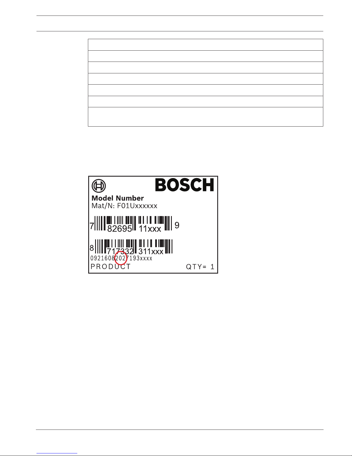
2.2 Bosch Security Systems, Inc. product manufacturing dates
Use the serial number located on the product label and refer to the Bosch Security Systems,
Inc. website at http://www.boschsecurity.com/datecodes/.
The following image shows an example of a product label and highlights where to find the
manufacturing date within the serial number.

16 en | System overview Control Panels
2018.07 | 10 | F.01U.303.996 Installation Manual Bosch Security Systems, Inc.
3 System overview
This section has the following information:
– Parts list, page 16
– Control panel capacities, page 16
– Accessories, page 20
– Features, page 17
3.1 Parts list
Control panels ship assembled from the factory with the following parts:
Literature
– Control Panels (B9512G/B8512G) UL Installation Manual
– Control Panels (B9512G/B8512G/B5512/B4512/B3512) Operation Manual
– Control Panels (B9512G/B8512G) SIA Quick Reference Guide
– Control Panels (B9512G/B8512G) Documentation CD
– Product Label in French
– 7000/9000 Series Point Chart Label
HW pack
– 1 kΩ EOL resistors
– Battery wires
Assembly
– PC board with protective cover
– Mounting skirt
– One #6 x 3/4-inch screw
3.2 Control panel capacities
Features B9512G/
B9512G-E
B8512G/
B8512G-E
Number of users 2000 500
Total number of doors 32
1
8
1
Number of cards/tokens 2000 500
Number of custom functions 32 8
Number of areas 32 8
Number of points 599 99
Number of outputs 599 99
Total number of keypads 32
2
16
2
Number of octo-intput modules (B208) 59 9
Number of POPEX modules (B299) 6 1
Number of octo-output modules (B308) 59 9
Number of on-board Ethernet ports (“E” control panel variants do not include an
Ethernet port)
1 1
Number of B426 or B450 modules 2 2
Number of plug-in telephone communication modules (B430) 2 2

Control Panels System overview | en 17
Bosch Security Systems, Inc. Installation Manual 2018.07 | 10 | F.01U.303.996
Features B9512G/
B9512G-E
B8512G/
B8512G-E
Number of plug-in cellular modules (B440/B441/B442/B443/B444) 1 1
Number of auxiliary power supply modules (B520) 8 4
Number of wireless receivers (B810/B820) 1 1
Number of cameras
3
16 8
1
The control panel supports 32 doors using the optional B901 Access Control Module. The control panel
supports up to 8 doors using the optional D9210C Access Control Interface Module.
2
The control panel supports up to 16 of the keypads as SDI keypads.
3
Bosch IP cameras use is supplementary in UL Listed systems.
3.3 Features
This section explains the control panel's notable features.
3.3.1 SDI2 interconnect wiring
The control panel and most compatible modules have interconnect wiring connectors. You can
use the connectors in place of terminal wiring. In installations with multiple SDI2 modules,
using interconnect wiring makes the installation quicker and easier than using terminal strip
wiring. You use any combination of terminal and interconnect wiring to wire multiple modules
in parallel, but do not wire a single module to the control panel using both terminal and
interconnect wiring.
The interconnect wiring connectors are "keyed" (interconnect wiring plug can fit in only one
direction).
Each SDI2 module that has an SDI2 interconnect wiring connector comes with a 12 in (30 cm)
interconnect cable.
3.3.2 Points
The control panels provide up to the following number of points of protection:
– B9512G. 599
– B8512G. 99
Point programming parameters determine the control panel’s response to open and shorted
conditions on the sensor loop for the point. Several options allow individual point
programming to custom-fit the protection to the installation.
The control panel has eight on-board points, points 1 to 8.
The SDI2 bus allows for point expansion with:
– One or more B208.
– One or more B299.
– A B810 wireless receiver or B820 SDI2 Inovonics Interface Module.
The B600 Retrofit (ZONEX) module allows for connection to a D8125 (D8125MUX, D8125INV)
module for point expansion.
3.3.3 Areas and accounts
The control panels provide up to the following number of areas:
– B9512G. 32
– B8512G. 8
You can assign all points to a single area or distribute them over multiple areas.
Users can turn areas on and off individually or together. You can assign an authority level to a
user that allows the user to turn an area on from a remote keypad in another area.

18 en | System overview Control Panels
2018.07 | 10 | F.01U.303.996 Installation Manual Bosch Security Systems, Inc.
Create up to the up to the following number of separate accounts when you assign each area
its own account number:
– B9512G. 32
– B8512G. 16
Assigning the same account number to different areas groups them together in a single
account.
Area options include exit tone and delay, separate fire and burglary outputs, and multiple
opening and closing windows. Use area types to create area relationships.
For systems with more than one area, all areas must be under the responsibility of one
ownership and management. This may be a group of buildings attached or unattached and
may even have different addresses but are under the responsibility of someone having mutual
interest (other than the alarm installing company). This does not apply to strip mall
applications where each independent business must have their own separate alarm system.
An example for a commercial system would be a business that has an OFFICE area and a
WAREHOUSE area in a building where each area can be armed or disarmed independently.
As a residential example a system could be configured with the garage and house as separate
areas.
In each of the examples above, all of the areas are under the sole responsibility of a single
owner.
In multi-area systems, the bell (or siren) and control panel must be in one of the protected
areas.
The bell or siren must be located where it can be heard by users who turn areas on and off
(arm and disarm).
3.3.4 Digital communication
The control panel uses its built-in Ethernet connection and one of the following to send to
send reports to the central station receiver:
– Conettix Ethernet communication module (B426)
– Conettix plug-in cellular module (B440/B440-C/B441/B441-C/B442/B443/B444)
– Plug-in telephone communication module (B430)
The control panel sends reports in the Modem4 or the ANSI-SIA Contact ID format.
The system can route Event Reports to four different destinations through an IP network or
the telephone network (PSTN). Program primary and backup reporting destinations for each.
A custom option allows you to specify which Event Reports the system sends.
3.3.5 Keypads
The control panels provide up to the following number of keypads:
– B9512G. 32, including up to 16 SDI keypads
– B8512G. 16, including up to 16 SDI keypads
The control panel supervises all SDI2 keypads. Supervision for the 16 SDI keypads is
configurable.
3.3.6 Events
Event memory
The control panel retains point alarm and trouble events for each area in event memory. You
can view event memory on a keypad. Turning an area on clears the event memory for that area.
Control Panels System overview | en 19
Bosch Security Systems, Inc. Installation Manual 2018.07 | 10 | F.01U.303.996
Event log
The event log stores local and reported events. The event log includes information such as
time, date, event, area, point, and user. View the event log from a keypad or use RPS or the
Installer Services Portal programming tool (available in Europe, Middle East, Africa, and China)
to remotely retrieve event information. When the event log reaches a programmed threshold
of stored events, it can send an optional report to a receiver.
The control panels store up to the following number of events:
– B9512G. 10,192
– B8512G. 2,048
3.3.7 Programming
Use RPS or the Installer Services Portal programming tool (available in Europe, Middle East,
Africa, and China) to program the control panels. You can connect to the control panel using a
network connection (on-board Ethernet port, cellular module, B426 Conettix Ethernet
Communication Module, or telephone module), or locally using the control panel’s on-board
Ethernet port or USB port. (To program with the USB port connection, use the B99 USB 2.0
Type A Male to Type A Male cable by Bosch.) You can also use a keypad for select
programming.
Refer to RPS Help, the Installer Services Portal programming tool Help, or the control panel’s
Program Entry Guide, and to Keypad Installer menu, page 123 for programming options.
Notice!
After system installation and any control panel programming, perform a complete system test
(a UL 864 requirement). A complete system test includes testing the control panel, all
devices, and communication destinations for proper operation.
3.3.8 Firmware updates
The system can update the firmware remotely:
– Control panel updates. Remotely update the control panel firmware for easy feature
enhancements without replacing ROM chips.
– Module update support. Remotely update the firmware on connected SDI2 modules for
easy feature enhancements without visiting each individual module.
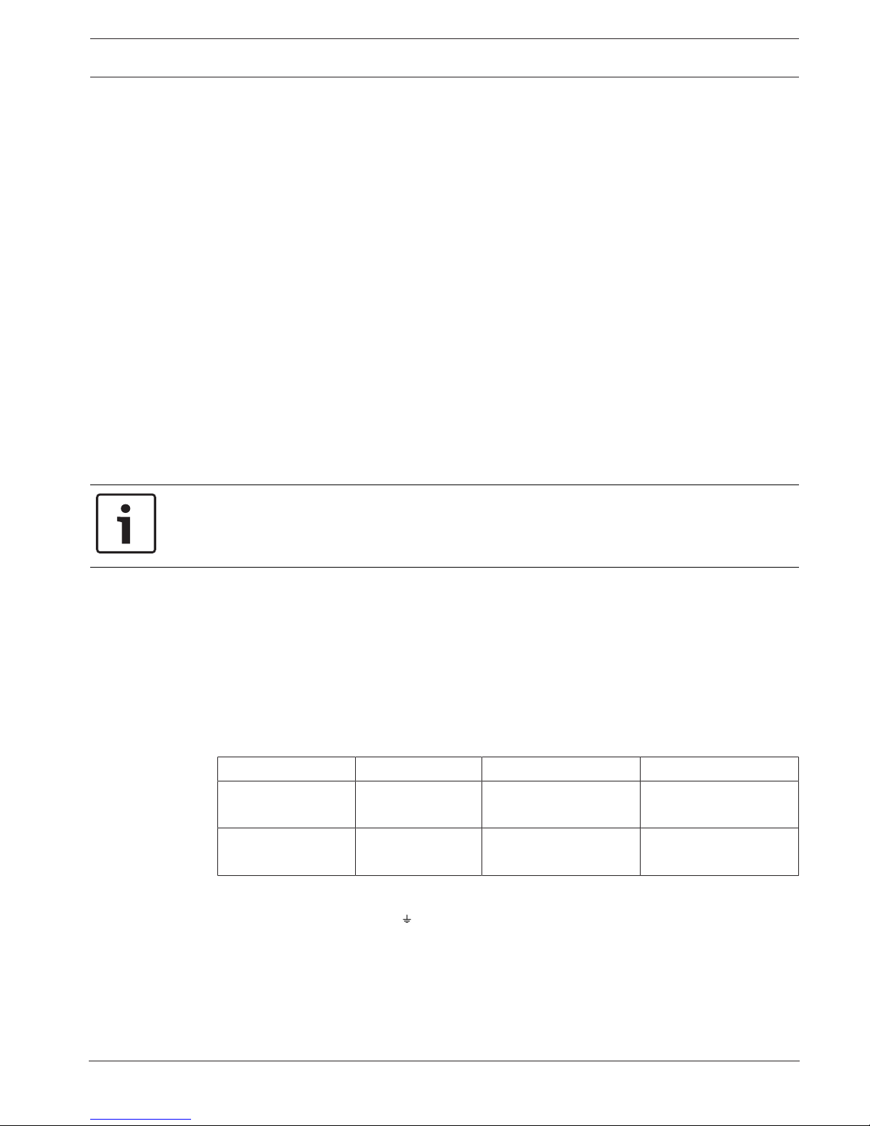
3.3.9 Access control
The control panels support up to the following number of modules, cards, and tokens:
Control panel B901 D9210C Cards or token
B9512G 32 8 (combine with B901
for a total of 32)
– B901. 2,000
– D9210C. 999
B8512G 8 8 (combine with B901
for a total of 8)
– B901. 500
– D9210C. 500
3.3.10 Ground fault detection
The earth ground Terminal 10 on the control panel is electrically isolated from all other
terminals to allow the control panel to detect ground fault conditions. Ground Fault Detect is
configured in programming.
3.3.11 Dual authentication
With Dual Authentication enabled, the control panel requires two forms of identification
before it processes certain system commands, including turning off the system and opening
doors.
20 en | System overview Control Panels
2018.07 | 10 | F.01U.303.996 Installation Manual Bosch Security Systems, Inc.
A standard system user must have a passcode, a credential (token or card), and appropriate
command authority permissions assigned in the door to the assigned area of the keypad.
When enabled at a keypad, only the following Passcode Functions require access credentials
with passcode entry:
– Turn On/Turn Off
– Cycle Door (Grant Access)
– Cycle Output
– Auto Re-arm
Notice!
Plan ahead
If you plan to use Dual Authentication with access control, install a keypad close to the door
controller.
3.3.12 Recent closing
If a point with a point type set to 1, 2, or 3 goes into alarm within 2 minutes after the exit
delay expires, the control panel sends a Recent Closing Alarm. This feature is always enabled
and cannot be configured. The alarm with recent closing event creates new Modem4
messages that the central station might need to add to their automation software. For details
of central station data changes, refer to Events in the Modem4/ModemIIIa2 Messages section of
the Appendix in the Conettix D6600/D6100i Computer Interface Manual (P/N: 4998122703).
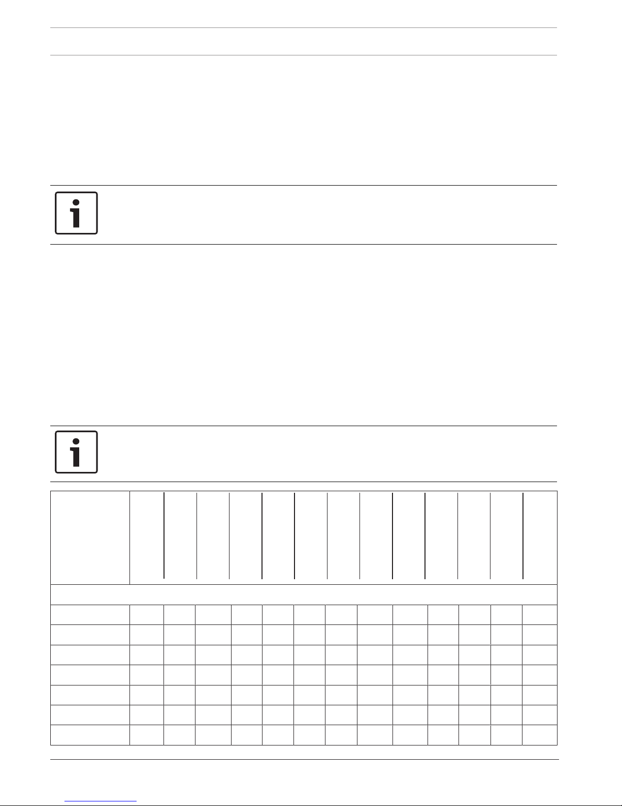
3.4 Accessories
Accessory compatibility
The following table lists accessories that are compatible with the control panel. An X in a
column indicates the accessory is compatible with the standard.
Notice!
Where the fire alarm transmitter is sharing on-premise communications equipment, the
shared equipment must be UL Listed (ITE or fire protective signaling).
Model
number
CAN/ULC S303 -
Local
Burglary
CAN/ULC S304 -
Signal Receiving
Centre and Premise
CAN/ULC S545 -
Residential
Fire
ULC-ORD C1023 -
Household
Burglary
ULC-ORD C1076 -
Proprietary
Burglary
UL1610 -
Central Station
Burglary
UL1076 -
Proprietary
Burglary
UL985 -
Household
Fire
UL365 -
Police Connected
Burglary
UL609 -
Local Burglary
UL636 -
Holdup
UL864 -
Commercial
Fire
UL1023 -
Household
Burglary
Keypads
B915/B915I* X X X X X X X X X X X X
B920* X X X X X X X X X X X X
B921C*
1
X X X X X X X X
B925F* X X X X X X X X X X X X X
B926F* X X X
B930* X X X X X X X X X X X X
B942/B942W* X X X X X X X X X X X X

Control Panels System overview | en 21
Bosch Security Systems, Inc. Installation Manual 2018.07 | 10 | F.01U.303.996
Model
number
CAN/ULC S303 -
Local
Burglary
CAN/ULC S304 -
Signal Receiving
Centre and Premise
CAN/ULC S545 -
Residential
Fire
ULC-ORD C1023 -
Household
Burglary
ULC-ORD C1076 -
Proprietary
Burglary
UL1610 -
Central Station
Burglary
UL1076 -
Proprietary
Burglary
UL985 -
Household
Fire
UL365 -
Police Connected
Burglary
UL609 -
Local Burglary
UL636 -
Holdup
UL864 -
Commercial
Fire
UL1023 -
Household
Burglary
D1255/
D1255B**
X X X X X X X X X X
D1255RB** X X X X X X X X X X X
D1255W** X X X X X X X X X X
D1256RB** X X X X X X X X X X X
D1257RB** X X X X X X X X X X X
D1260/
D1260B**
2
X X X X X X X X X X
Transformers, batteries, power supplies, etc.
B520 X X X X X X X X X X X X X
D122/D122L Suitable for use on approved applications.
D126 Suitable for use on approved applications.
D1218 Suitable for use on approved applications.
D1640 Suitable for use on approved applications in the USA.
D1640-CA Suitable for use on approved applications in Canada.
Enclosures
BATB-40/
BATB-80
X X X
B8103 X X X X X X X X X
D8103 X X X X X X X X X
D8109 X X X X X X X X X
D8108A X X X X X X X X X X
D8004 X X X X X X
Expansion modules
B208 X X X X X X X X X X X X
B299 X X X X X X X X X X X X X
B308 X X X X X X X X X X X X
B600 X X X X X X X X X X X X X
D125B
3
X X X X X X X X X X X
D129 X X X X X X X X X X

22 en | System overview Control Panels
2018.07 | 10 | F.01U.303.996 Installation Manual Bosch Security Systems, Inc.
Model
number
CAN/ULC S303 -
Local
Burglary
CAN/ULC S304 -
Signal Receiving
Centre and Premise
CAN/ULC S545 -
Residential
Fire
ULC-ORD C1023 -
Household
Burglary
ULC-ORD C1076 -
Proprietary
Burglary
UL1610 -
Central Station
Burglary
UL1076 -
Proprietary
Burglary
UL985 -
Household
Fire
UL365 -
Police Connected
Burglary
UL609 -
Local Burglary
UL636 -
Holdup
UL864 -
Commercial
Fire
UL1023 -
Household
Burglary
D192G X X X X X X X X X X
D8125 X X X X X X X X X X X
D8125MUX X X X X X X X X X X
D8128D X X X X X X X X X X X
D8129 X X X X X X X X X X X
D8130 X X X X X X X X X X
D9127U/T X X X X X X X X X X X
DS7461i X X X X X X
DS7465i X X X X X X
Wireless
B810
4
X X X X X X X
B820
5
X X X X X X X
Communicators
B426 X X X X X X X X X X X
B430 X X X X X X X X X X X X X
B440 X X X X X X X X
B441 X X X X X X X X
B442
7
X X X X X X X X X X X X X
B443
7
X X X X X X X X X X X X X
B444 X X X X X X X X
B450 X X X X X X X X X X X X
Accessories
D113 X X X X X X
D130 X X X X X X X X X X
D132A X X
D133 X X X X X X
D134 X X X X X X
D161 Suitable for use on approved applications.
D162 Suitable for use on approved applications.
Control Panels System overview | en 23
Bosch Security Systems, Inc. Installation Manual 2018.07 | 10 | F.01U.303.996
Model
number
CAN/ULC S303 -
Local
Burglary
CAN/ULC S304 -
Signal Receiving
Centre and Premise
CAN/ULC S545 -
Residential
Fire
ULC-ORD C1023 -
Household
Burglary
ULC-ORD C1076 -
Proprietary
Burglary
UL1610 -
Central Station
Burglary
UL1076 -
Proprietary
Burglary
UL985 -
Household
Fire
UL365 -
Police Connected
Burglary
UL609 -
Local Burglary
UL636 -
Holdup
UL864 -
Commercial
Fire
UL1023 -
Household
Burglary
D185 X
ICP-SDI-9114 X X X X X X X X X X
ICP-EZTS X X X X X X X X X X X
Door control (Access)
B901 X X X X X X X X X X X
D9210C X X X X X X X X X X X
*Approved for use on combination fire and burg systems when on a different bus from fire devices.
**Combination fire and burg systems using SDI devices might require an ICP-SDI-9114 to separate fire and
intrusion devices onto separate circuits.
1
ULC listed for Proprietary Burglary and Residential Fire only.
2
Keypad version 1.04 or higher.
3
Refer to the Dual Class B Initiating Module (D125B) Installation Instructions for compatible D125B devices.
4
Refer to the section within this section for compatible RADION devices.
5
Refer to the section within this section for compatible Inovonics devices.
7
Check for availability in your region.
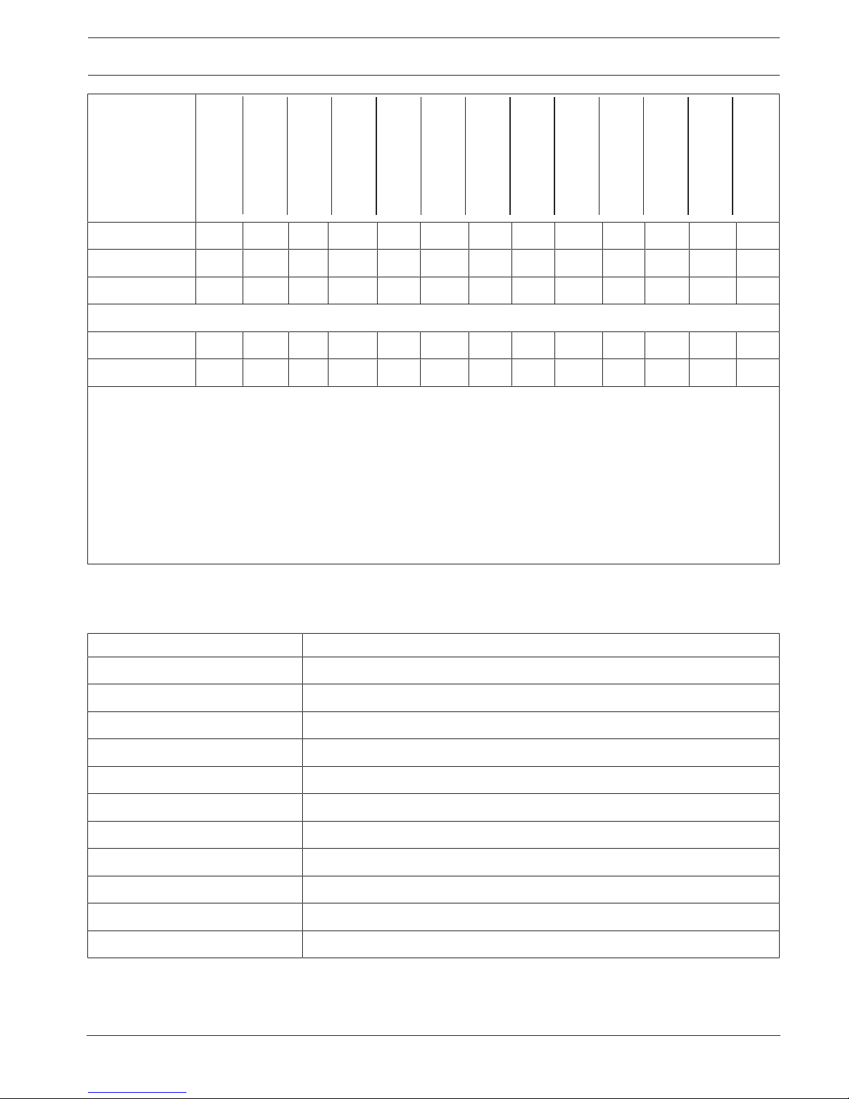
Compatible detectors
The following is a sampling of wired detectors suitable for use on approved applications.
Other UL listed devices are available.
Model Name
FCC-380 Carbon Monoxide Detector
F220-P with F220-B6 Photoelectric Smoke Detector with Detector Base
HUB Potter HUB Holdup Button
ISC-BDL2-WP12 Wheelock MB Series 12V 6 " Fire Bell (Red)
MB-G6-12-R Wheelock MB Series 12V 6 " Fire Bell (Red)
ZX776Z PIR Motion Sensor [15 m (50 ft)] with POPIT
ZX794Z PIR Motion Sensor [24 m (80 ft)] with POPIT
ZX865 PIR/Microwave Motion Sensor [+1.7°C (+35°F)] with POPIT
ZX938Z PIR Motion Sensor [18 m (60 ft)] with POPIT
ZX970 PIR/Microwave Motion Sensor [+1.7°C (+35°F)] with POPIT
5110/4001-42 Rothenbuhler High Security Bell
B810 wireless receiver compatible accessories
Refer to RADION receiver SD (B810) Installation Guide.

24 en | System overview Control Panels
2018.07 | 10 | F.01U.303.996 Installation Manual Bosch Security Systems, Inc.
Model Name Description
RFBT-A RADION specialty Bill trap
RFDL-11-A RADION TriTech Motion detector
RFDW-RM-A RADION contact RM Recessed door/window contact
RFDW-SM-A RADION contact SM Surface mount door/window contact
RFGB-A RADION glassbreak Glassbreak detector
RFKF-FB-A RADION keyfob FB Four-button key fob
RFKF-FBS-A RADION keyfob FB Four-button encrypted key fob
RFKF-TB-A RADION keyfob TB Two-button key fob
RFKF-TBS-A RADION keyfob TB Two-button encrypted key fob
RFPB-SB-A RADION panic SB Single button panic
RFPB-TB-A RADION panic TB Two button panic
RFRP-A RADION repeater Repeater
RFSM-A RADION smoke
1
Smoke detector
RFPR-12-A RADION PIR PIR detector
RFPR-C12-A RADION PIR C PIR curtain detector
RFUN-A RADION universal Universal transmitter
1
UL 985 only.
B820 SDI2 Inovonics Interface Module compatible accessories
Model Name
EN1210 Universal Transmitter (Single-input)
EN1210EOL Universal Transmitter with EOL Resistor
EN1210W Door-Window Transmitter with Reed Switch
EN1215EOL Universal Transmitter with Wall Tamper and EOL Resistor
EN1215WEOL Door-Window Transmitter with Wall Tamper, Reed Switch, and EOL Resistor
EN1223D* Water-resistant Pendant Transmitter (Double-button)
EN1223S* Water-resistant Pendant Transmitter (Single-button)
EN1224-ON Multiple-Condition On/Off Pendant Transmitter
EN1233D Necklace Pendant Transmitter (Double-button)
EN1233S Necklace Pendant Transmitter (Single-button)
EN1235D Beltclip Pendant Transmitter (Double-button)
EN1235DF Fixed-location Transmitter (Double-button)
EN1235S Beltclip Pendant Transmitter (Single-button)
EN1235SF Fixed-location Transmitter (Single-button)

Control Panels System overview | en 25
Bosch Security Systems, Inc. Installation Manual 2018.07 | 10 | F.01U.303.996
Model Name
EN1242 Smoke Detector Transmitter
EN1247 Glass-break Detector Transmitter
EN1249 Bill Trap Transmitter
EN1260 Wall Mount Motion Detector
EN1261HT High Traffic Motion Detector
EN1262 Motion Detector With Pet Immunity
EN1265 360° Ceiling Mount Motion Detector
EN4200 Serial Receiver
EN4204R Four Zone Add-on Receiver With Relay Outputs
EN5040-T High Power Repeater With Transformer
EN7016* Wireless Survey Kit
ENKIT-SDI2 B820 and EN4200 Kit
*Not investigated by UL.
Notice!
No wireless detectors have been approved for use with alarm verification points.
For specific installation and operation instructions, please refer to manufacturers' manuals.
D125B 2-wire smoke compatibility table
Refer to the Dual Class B Initiating Module (D125B) Installation Instructions.
3.4.1 Compatible UL Listed Synchronization (Sync) modules and strobes
Notice!
For UL 864 compliance, use only these models of synchronization modules and strobes.
Synchronization modules and strobes capacity
Device Maximum number of devices
1
Wheelock control panel powered devices 4
Wheelock 12 VDC external powered devices 11
Wheelock 24 VDC external powered devices 33
System Sensor control panel powered devices 4
System Sensor 12 VDC external powered devices 11
System Sensor 24 VDC external powered devices 33
1
High current settings reduces the quantity.

26 en | System overview Control Panels
2018.07 | 10 | F.01U.303.996 Installation Manual Bosch Security Systems, Inc.
Wheelock synchronization module DSM/SM-24 and strobe compatibility
Strobe model Product Description
AH Series Wall or Ceiling-mount
Electronic Horns
AH-24-R 24 VDC, Red
AH-24-W 24 VDC, White
AH-24WP-R 24 VDC, Outdoor, Weatherproof, Red
AS Series Audible Strobes AS-241575W-FR 24 VDC, 15 cd, (75 cd on axis), Two-wire, Wall-mount, Red
AS-24MCC-FR 24 VDC, 15 cd to 95 cd, Ceiling-mount, Red
AS-24MCC-FR-V 24 VDC, Variable cd, Ceiling-mount, Red
AS-24MCC-FW 24 VDC, 15 cd to 95 cd, Square, Ceiling-mount, White
AS-24MCCH-FR 24 VDC, 115/177 cd, Square, Ceiling-mount, Red
AS-24MCCH-FW 24 VCD, 115/177 cd, Square, Ceiling-mount, White
AS-24MCW-FR 24 VDC, Variable cd, Wall-mount, Red
AS-24MCW-FW 24 VDC, Variable cd, Wall-mount, White
AS-24MCWH-FR 24 VDC, 135/185 cd, Square, Wall-mount, Red
AS-24MCWH-FW 24 VDC, 135/185 cd, Square, Wall-mount, White
ASWP-2475W-FR 24 VDC, 75 cd, Red
CH70 Series Wall-mount Chimes
and Chime Strobes
CH70-24-R 24 VDC, Square, Red
CH70-24-W 24 VDC, Square, White
CH70-241575W-FR 24 VDC, 15 cd (75 cd on axis), Square, Red
CH70-24MCW-FR 24 VDC, Variable cd, Red
CH70-24MCW-FW 24 VDC, Variable cd, White
CH70-24MCWH-FR 24 VDC, 135 cd to 185 cd, Square, Red
CH70-24MCWH-FR 24 VDC, 135 cd to 185 cd, Square, White
HS4 Series Two or Four-wire
Horn Strobes
HS4-241575W-FR 24 VDC, 15/75 cd, Four-wire, Red
HS4-241575W-FW 24 VDC, 15/75 cd, Four-wire, White
HS4-24MCW-FR 24 VDC, 15 to 110 cd, Four-wire, Square, Red
HS4-24MCW-FW 24 VDC, 15 to 110 cd, Four-wire, Square, White
HS4-24MCWH-FR 24 VDC, 135 to 185 cd, Four-wire, Square, Red
HS4-24MCWH-FW 24 VDC, 135 to 185 cd, Four-wire, Square, White
NS Series Horn Strobes NS-241575W-FR 24 VDC, 15/75 cd, Red
NS-241575W-FW 24 VDC, 15/75 cd, Red
NS-24MCW-FR 24 VDC, Variable cd, Mini, Wall-mount, Red
NS-24MCW-FW 24 VDC, Variable cd, Mini, Wall-mount, White
RSS Series Strobes RSS-241575W-FR 24 VDC, 15/75 cd, Synchronized, Red

Control Panels System overview | en 27
Bosch Security Systems, Inc. Installation Manual 2018.07 | 10 | F.01U.303.996
Strobe model Product Description
RSS-241575W-FW 24 VDC, 15/75 cd, Synchronized, White
RSS-24MCC-FR 24 VDC, 15 to 95 cd, Ceiling-mount, Red
RSS-24MCC-FR-V 24 VDC, Variable cd, Ceiling-mount, Red
RSS-24MCC-FW 24 VDC, 15 to 95 cd, Square, White
RSS-24MCC-NW 24 VDC, 15 to 95 cd, Ceiling-mount, White
RSS-24MCCH-FR 24 VDC, 115 to 177 cd, Ceiling-mount, White
RSS-24MCCH-FW 24 VDC, 115 to 177 cd, White
RSS-24MCCHR-FR 24 VDC, 115 to 177 cd, Ceiling-mount, Red
RSS-24MCCHR-FW 24 VDC, 115 to 177 cd, Ceiling-mount, White
RSS-24MCCR-FR 24 VDC, 15 to 95 cd, Ceiling-mount, Red
RSS-24MCCR-FW 24 VDC, 15 to 95 cd, Ceiling-mount, White
RSS-24MCW-FR 24 VDC, Variable cd, Wall-mount, Red
RSS-24MCW-FW 24 VDC, Variable cd, Wall-mount, White
RSS-24MCWH-FR 24 VDC, 135 to 185 cd, Wall-mount, Red
RSS-24MCWH-FW 24 VDC, 135 to 185 cd, Wall-mount, White
RSSP-241575W-FR 24 VDC, 15/75 cd, Plate, Red
RSSP-24MCW-FR 24 VDC, 15 to 110 cd, Red
RSSP-24MCWH-FR 24 VDC, 135 to 185 cd, Retrofit, Red
RSSR-24110C-NW 24 VDC, 110 cd, Ceiling-mount, White
RSSR-2475C-NW 24 VDC, 75 cd, Ceiling-mount, White
RSSR-2475W-AAR 24 VDC, 74 cd, Square, Wall-mount, Red
RSSWP-2475W-FR 24 VDC, 75 cd, Waterproof, Red
RSSWP-2475W-FW 24 VDC, 75 cd, Outdoor, White
Exceder LED Low Frequency
Sounder
LLFHNR-AL LED LF HN RED,2W,WALL,24V,ALERT
LLFHNW-AL LED LF HN WHT,2W,WALL,24V,ALERT
LLFHNR-CO LED LF HN RED,2W,WALL,24V,CO
LLFHNW-CO LED LF HN WHT,2W,WALL,24V,CO
LLFHNR-N LED LF HN RED,2W,WALL,24V,NO LTR
LLFHNW-N LED LF HN WHT,2W,WALL,24V,NO LTR
LLFHSR LED LF HN STR,RED,2W,WALL,24V,110CD, FIRE
LLFHSW LED LF HN STR,WHT,2W,WALL,24V,110CD, FIRE
LLFHSR-AL LED LF HN STR,RED,2W,WALL,24V,110CD, ALERT

28 en | System overview Control Panels
2018.07 | 10 | F.01U.303.996 Installation Manual Bosch Security Systems, Inc.
Strobe model Product Description
LLFHSW-AL LED LF HN STR,WHT,2W,WALL,24V,110CD, ALERT
LLFHSR-CO LED LF HN STR,RED,2W,WALL,24V,110CD, CO
LLFHSW-CO LED LF HN STR,WHT,2W,WALL,24V,110CD, CO
LLFHSR-N LED LF HN STR,RED,2W,WALL,24V,110CD, NO LTR
LLFHSW-N LED LF HN STR,WHT,2W,WALL,24V,110CD,NO LTR
Wheelock synchronization module DSM/SM-12/24 and strobe compatibility
Strobe model Product Description
HN Series Wall or Ceiling-mount
Horns
HN 12/24 VDC, Horn, Wall-mounting
HN-C 12/24 VDC, Horn, Wall or Ceiling-mount
HS Series Wall or Ceiling-mount
Strobes
HS 12 VDC, 15/15-75 cd, Wall-mount
24 VDC, 15/15-75/30/75/95/110/135/185 cd, Wall-mount
HS-C 12 VDC, 15 cd, Ceiling-mount
24 VDC, 15/30/60/75/115/150/177 cd, Ceiling-mount
ST Series Wall or Ceiling-mount
Strobes and Horns
ST 12 VDC, 15/15-75 cd, Wall-mount
24 VDC, 15/15-75/30/75/95/110/135/185 cd, Wall-mount
ST-C 12 VDC, 15 cd, Ceiling-mount
24 VDC, 15/30/60/75/95/115/150/177 cd, Ceiling-mount
ZNH Series Wall or Ceilingmount Horns
ZNH-R 12/24 VDC, Flush, Square, Red
ZNH-W 12/24 VDC, Flush, Square, White
ZNS Series Wall or Ceiling-mount
Horn Strobes
ZNS-MCW-FR 24 VDC, Selectable 15/30/75/110 cd, Red
ZNS-MCW-FW 24 VDC, Selectable 15/30/75/110 cd, White
ZNS-MCWH-FR 24 VDC, 135/185 cd, Square, Red
ZNS-MCWH-FW 24 VDC, 135/185 cd, Square, White
ZRS Series Strobe Appliances ZRS-MCW-FR 24 VDC, Selectable 15/30/75/110 cd, Red
ZRS-MCW-FW 24 VDC, Selectable 15/30/75/110 cd, White
ZRS-MCWH-FR 24 VDC, Selectable 135/185 cd, Wall, Red
ZRS-MCWH-FW 24 VDC, Selectable 135/185 cd, Wall, White
ZRS-MCC-FR 24 VDC, Selectable 15/30/75/95 cd, Red
ZRS-MCC-FW 24 VDC, Selectable 15/30/75/95 cd, White
ZRS-MCCH-FR 24 VDC, Selectable 115/177 cd, Red
ZRS-MCCH-FW 24 VDC, Selectable 115/177 cd, White
Control Panels System overview | en 29
Bosch Security Systems, Inc. Installation Manual 2018.07 | 10 | F.01U.303.996
System Sensor synchronization module MDL3 strobe compatibility
Strobe model Product Description
PC24 Series Ceiling-mount Horn
Strobes
PC24115 24 VDC, 115 cd, Red, Ceiling mount
PC24115W 24 VDC, 115 cd, White, Ceiling mount
PC2415 24 VDC, 15 cd, Red, Ceiling mount
PC2415W 24 VDC, 15 cd, White, Ceiling mount
PC241575 24 VDC, 15 cd (75 cd on axis), Red, Ceiling mount
PC242575W 24 VDC, 15 cd (75 cd on axis), White, Ceiling mount
PC24177 24 VDC, 177 cd, Red, Ceiling mount
PC24177W 24 VDC, 177 cd, White, Ceiling mount
PC2430 24 VDC, 30 cd, Red, Ceiling mount
PC2430W 24 VDC, 30 cd, White, Ceiling mount
PC2475 24 VDC, 75 cd, Red, Ceiling mount
PC2475W 24 VDC, 75 cd, White, Ceiling mount
PC2495 24 VDC, 95 cd, Red, Ceiling mount
PC2495W 24 VDC, 95 cd, White, Ceiling mount
SC24 Series Ceiling-mount
Strobes
SC24115 24 VDC, 115 cd, Red, Ceiling mount
SC24115W 24 VDC, 115 cd, Round, White, Ceiling mount
SC2415 24 VDC, 15 cd, Round, Red, Ceiling mount
SC2415W 24 VDC, 15 cd, Round, White, Ceiling mount
SC241575 24 VDC, 15/75 cd, Round, Red, Ceiling mount
SC241575W 24 VDC, 15/75 cd, Round, White, Ceiling mount
SC24177 24 VDC, 177 cd, Round, Red, Ceiling mount
SC24177W 24 VDC, 177 cd, Round, White, Ceiling mount
SC2430 24 VDC, 30 cd, Round, Red, Ceiling mount
SC2430W 24 VDC, 30 cd, Round, White, Ceiling mount
SC2475 24 VDC, 75 cd, Round, Red, Ceiling mount
SC2475W 24 VDC, 75 cd, Round, White, Ceiling mount
SC2495 24 VDC, 95 cd, Round, Red, Ceiling mount
SC2495W 24 VDC, 95 cd, Round, White, Ceiling mount
Notice!
UL requirement
If you use 24 V devices, you must use a UL 1481 regulated power-limited power supply and a
D130 Relay Module. Refer to the D130 Installation Instructions.

30 en | Installation checklist Control Panels
2018.07 | 10 | F.01U.303.996 Installation Manual Bosch Security Systems, Inc.
4 Installation checklist
Before you install and operating the control panel, read these instructions. If you do not read
and understand these instructions, you cannot properly install and operate the control panel.
The instructions do not remove the need for training by authorized personnel.
Install, operate, test, and maintain this device according to the control panel Installation and
System Reference Guide. Failure to follow these procedures may cause the device not to
function properly. Bosch Security Systems Inc. is not responsible for any devices that are
improperly installed, tested, or maintained.
The control panel Installation and System Reference Guide does not have special information
about local requirements and safety issues. Information on such issues is provided only to the
extent that it is needed for operation of the device. Make sure that you are familiar with all
safety-related processes and regulations in your area. This also includes how to act in the
event of an alarm and the initial steps to take if a fire breaks out. The operating instructions
should always be available on site. It is a required part of the system and must be given to the
new owner if the system is ever sold.
Install the enclosure and wiring label
– Install the enclosure and wiring label
Install the control panel
– Mount the control panel
– Earth ground, page 32
Install and wire for telephone communication
– Telephone communications, page 44
Install and wire for IP communications
– IP communications, page 48
Install and wire the battery and the transformer
– Power supply, page 36
Begin to charge the battery while you install other devices
– Charge the battery
Install and wire arming devices
– Keypads, keyswitches, keyfobs and transmitters, page 58
Install and wire outputs
– On-board outputs, page 65
– Off-board outputs, page 68
Install and wire inputs
– On-board points, page 72
– Off-board points, page 75
– Wireless modules, page 85
Complete the installation
– Program and test the control panel, page 91
 Loading...