

Bosch B820 Installation Manual
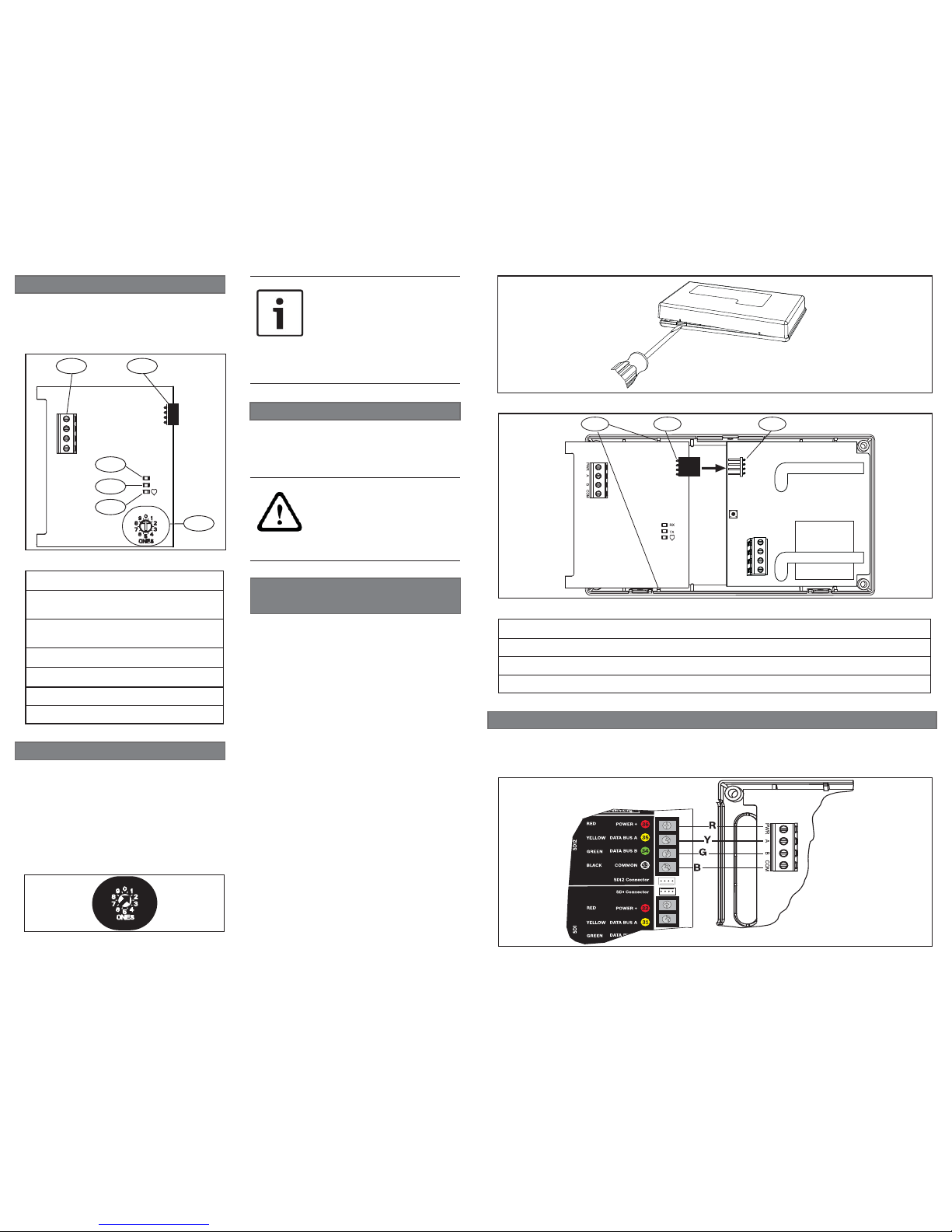
3.2 | Wire the B820 to the control panel
When you wire a B820 to a control panel, use the control panel SDI2 terminals labeled R,
Y, G, B (PWR, A, B, COM). Connect them to the module terminals labeled PWR, A, B, COM.
Refer to Figure 3.3.
Figure 3.3: Wiring to the control panel (GV4 Series control panel shown)
CAUTION!
Remove all power (AC and
battery) before making any
connections. Failure to do so
might result in personal injury
and/or equipment damage.
2 | SDI2 address settings
The address switch determines the address
for the B820 module. The control panel
uses the address for communications. Use
a slotted screwdriver to set the address
switch.
Set the address for the module to 1 prior to
installing it in the EN4200 housing. Figure
2.1 shows the address switches setting for
address 1.
NOTICE!
The module reads the address
switch setting only during power
up. If you change the switch after
you apply power to the module,
you must cycle the power to
the module in order for the new
setting to be enabled.
Figure 2.1: Address switch
After you set the address switch for the
proper address, install the module in the
EN4200 housing, and then wire the module
to the control panel.
3.1 | Install the B820 into
the EN4200 housing
Installing the module into the housing:
1. Use a slotted screwdriver to press
the housing release tab and separate the
housing. Refer to Figure 3.1.
2. Remove the backing from the Velcro
piece found in the product packaging to
reveal the Velcro adhesive.
3. Place the Velcro’s adhesive side onto
the back of the module.
4. Remove the remaining backing to use to
secure the module in the housing.
5. Insert the B820 module into the EN4200
housing, connecting the B820’s serial data
port to the EN4200’s serial data port. Refer
to Figure 3.2.
6. Gently apply pressure to the B820
module to snap it into the housing clips
and to apply the Velcro adhesive to the
housing.
Figure 3.1: Opening the EN4200 housing
Figure 3.2: Installing the B820 in the EN4200 housing
1 2 3
Callout ― Description
1 ― Housing clips to secure the module
2 ― B820 serial data port
3 ― EN4200 serial data port
3 | Installation
The B820 SDI2 Inovonics Interface Module
allows a control panel to interface with an
Inovonics EN4200 EchoStream Serial Receiver
through the SDI2 bus.
Callout ― Description
1 ― SDI2 Terminal strip (to control
panel)
2 ― Serial data port (to Inovonics
receiver)
3 ― Address switch
4 ― Heartbeat LED (blue)
5 ― TX (transmit) LED (green)
6 ― RX (receive) LED (green)
Figure 1.1: Module overview
1 | Overview
5
1
6
PWR A B COM
2
3
4
RX
TX
© 2016 Bosch Security Systems, Inc.
F.01U.265.460 | 06 | 2016.08
en Installation Guide
SDI2 Inovonics Interface Module
B820
Bosch Security Systems, Inc.
130 Perinton Parkway
Fairport, NY 14450
USA
www.boschsecurity.com
Bosch Sicherheitssysteme GmbH
Robert-Bosch-Ring 5
85630 Grasbrunn
Germany
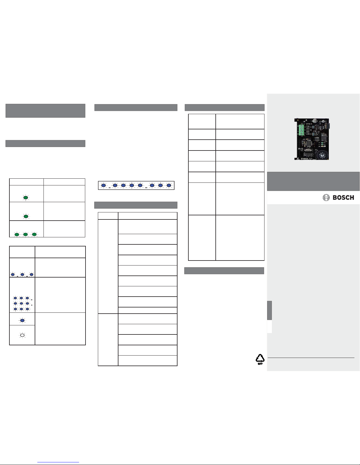
Flash
Pattern
Function
Flashes
once every
1 second
Normal state. Indicates
normal operation state.
3 quick
fl ashes
every 1
second
Communication error
state. Indicates (the
module is in a “no
communication state”)
resulting in an SDI2
communication error.
ON steady LED trouble state. Module
is not powered (for OFF
Steady only), or some
other trouble condition
prohibits the module from
controlling the heartbeat
LED.
OFF steady
Copyright
This document is the intellectual property of
Bosch Security Systems, Inc. and is protected
by copyright. All rights reserved.
Trademarks
All hardware and software product names
used in this document are likely to be
registered trademarks and must be treated
accordingly.
Bosch Security Systems, Inc. product
manufacturing dates
Use the serial number located on the
product label and refer to the Bosch Security
Systems, Inc. website at
http://www.boschsecurity.com/datecodes/.
In the following example, the version 1.4.3
shows as LED fl ashes:
[3 second pause] *___****___*** [3 second
pause, then normal operation].
Figure 5.1: Firmware LED fl ash patterns
7 | Specifi cations
Dimensions 3.2 in x 2.8 in x 0.60 in
(82.5 mm x 70 mm x
15.25 mm)
Voltage
(operating)
12 V nominal
Current
(maximum)
110 mA total for B820
module and the EN4200
Operating
temperature
+32°F to +122°F
(0°C to +50°C)
Relative
humidity
5% to 93% at +90°F
(+32°C) non-condensing
Terminal wire
size
12 AWG to 22 AWG
(2 mm to 0.65 mm)
SDI2 wiring Maximum distance -
Wire size:
600 ft (183 m) -
22 AWG (0.65 mm)
1000 ft (305 m) 18 AWG (1.02 mm)
(Unshielded wire only)
Compatibility B9512G/B9512G-E
B8512G/B8512G-E
B6512
B5512/B5512E
B4512/B4512E
B3512/B3512E
D9412GV4
D7412GV4
(Each control panel
supports one B820.)
6 | Certifi cations
Region
US UL 365 - Police Station
Connected Burglar Alarm Units
and Systems
UL 609 - Local Burglar Alarm
Units and Systems
UL 636 - Holdup Alarm Units
and Systems
UL 985 - Household Fire
Warning System Units
UL 1023 - Household Burglar
Alarm System Units
UL 1076 - Proprietary Burglar
Alarm Units and Systems
UL 1610 - Central Station
Burglar Alarm Units
CSFM - California Offi ce of The
State Fire Marshall
FCC Part 15 Class B
Canada CAN/ULC S303 - Local Burglar
Alarm Units and Systems
CAN/ULC S304 - Signal
Receiving Centre and Premise
ICES-003 - Information
Technology Equipment (ITE)
ULC-ORD C1023 - Household
Burglar Alarm System Units
ULC-ORD C1076 - Proprietary
Burglar Alarm Units and System
5 | Show the fi rmware version
To show the fi rmware version using an LED
fl ash pattern:
-
Remove the cover to the EN4200 housing.
Refer to
Section 3.1.
- If you removed the cover previously, press
and release the tamper switch spring.
The heartbeat LED stays OFF for 3 seconds
before indicating the fi rmware version. The
LED pulses the major, minor, and micro
digits of the fi rmware version, with a 1
second pause after each digit.
4 | LED descriptions
The B820 module includes three LEDs:
TX (transmit) LED to indicate data
transmission, RX (receive) LED to indicate
data receipt, and Heartbeat LED to
indicate the status of the SDI2 connection.
Refer to Tables 4.1 and 4.2.
Table 4.2: Heartbeat LED descriptions
Flash pattern Function
TX (transmit) ON
steady
Occurs when
transmitting data to
the receiver.
RX (receive) ON
steady
Occurs when
receiving data from
the receiver.
RX (receive) 3
quick fl ashes
Occurs when a
wireless device is
detected.
Table 4.1: TX and RX LED descriptions
3.3 | Mount the EN4200
housing
Refer to the EN4200 EchoStream Serial
Receiver Installation Instructions for
mounting instructions.
 Loading...