

Bosch ARD-SELECT-BP, ARD-SELECT-BPK, ARD-SELECT-BO, ARD-SELECT-BOK, ARD-SELECT-WP Installation manual
...Page 1
1 2
3
4
5
6
7
8
9
C
0
E
LECTUS select
ARD‑SELECT‑BP | ARD‑SELECT‑BPK | ARD‑SELECT‑BO |
ARD‑SELECT‑BOK | ARD‑SELECT‑WP | ARD‑SELECT‑WPK |
ARD‑SELECT‑WO | ARD‑SELECT‑WOK | ARA‑SELECT‑WWA |
ARA‑SELECT‑SWA
en
Installation manual
Page 2

Page 3

LECTUS select Table of contents | en 3
Table of contents
1
General 4
1.1 Introduction 4
1.2 Safety 5
1.3 Disposal 6
1.4 Components 7
1.5 Functional requirements 8
1.5.1 OSDP 10
1.5.2 Phg_crypt 10
1.5.3 Firmware overview 10
1.6 RFID technology 11
1.7 Transponder data 12
1.8 Reading distances 13
2
Installation 15
2.1 General 15
2.1.1 Mechanical structure of the flush-mount version 15
2.1.2 Mechanical structure of the surface-mount version 15
2.2 Installing data and supply lines 16
2.3 Assembly preparation 17
2.4 Assembling the reader 18
2.5 Assembling the reader module 20
2.5.1 Configuring the reader (DIP switches) 20
2.5.2 Connecting and mounting the reader module 21
2.5.3 Unmounting the reader module 22
2.5.4 Resetting OSDP-key 22
3
4
5
Care instructions 23
Technical specifications 24
More information 26
Bosch Security Systems B.V.
Installation manual
2021-02 | 01 | F.01U.389.837
Page 4
4 en | General LECTUS select
1 2
3
4
5
6
7
8
9
C
0
E
1 General
1.1 Introduction
This installation manual is aimed at authorized service providers.
The installation manual contains instructions on the installation and configuration of the
Bosch Security Systems proximity reader LECTUS select.
2021-02 | 01 | F.01U.389.837
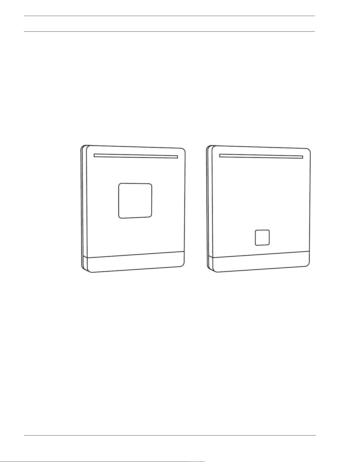
Figure1.1: LECTUS select readers
Installation manual
Bosch Security Systems B.V.
Page 5
LECTUS select General | en 5
!
!
!
i
i
1.2 Safety
– Read, observe and keep the instructions - the entire safety and operating instructions
must be read and correctly followed before the readers are operated.
– Take all warnings into account - follow all warnings on the devices and in the operating
instructions.
– Power sources - the readers should only be operated with the recommended power
sources. If you are unsure whether you can use a specific power supply, contact your
dealer.
Warning!
Risk of damage to the equipment!
Always switch off the power supply to the device before making changes to the installation.
Do not connect or disconnect any plugs, data cables or screws while the power supply is
switched on.
Warning!
Health and Safety!
Installation must be carried out in accordance with local fire, health and safety regulations. A
secured door must be installed as part of an escape route and must have:
- a fail-safe lock. the door must be released in the event of power loss. Ideally, a solenoid lock
should be used.
- an emergency switch with a glass cover for manual breaking the circuit, so that the fail-safe
lock can be de-energized immediately in an emergency.
Warning!
Risk of damage!
Protect the device against electrostatic discharge by observing the ESD instructions before
unpacking or touching the plug and the electronics.
Notice!
- The devices are equipped according to EN 60950, with protection class III.
- During the installation, make sure that the facility requirements placed by the corresponding
device safety standard are not influenced in an impermissible manner, compromising product
safety.
- Electromagnetic compatibility: The devices are designed for use in residential, business,
commercial and industrial areas.
Notice!
Installation and assembly of electrical components must be carried out by a qualified
electrician.
Caution!
The circuit board is at risk from electrostatic discharge. Appropriate precautionary measures
(grounding, etc.) must be observed.
Bosch Security Systems B.V.
Installation manual
2021-02 | 01 | F.01U.389.837
Page 6
6 en | General LECTUS select
Danger!
- The device must be operated in a fully assembled state only.
- Before connecting the device to the power supply, make sure that the connected operating
voltage does not exceed the permitted values according to the technical specifications.
- Additional safety measures should be enforced whenever there is a risk that failure of
malfunction of the device might pose a risk to humans, animals or damage to the equipment,
this must be prevented with additional safety measures (limit switches, protective
equipment, etc.).
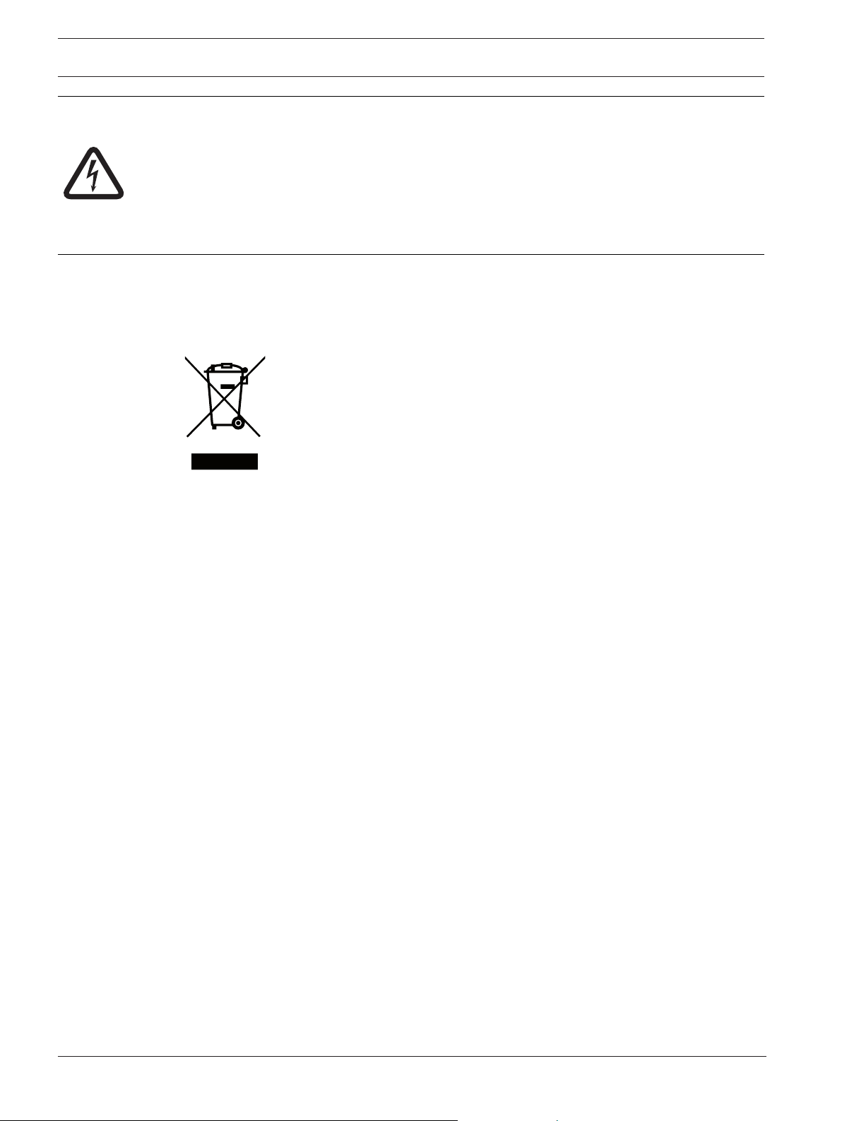
1.3 Disposal
Old electrical and electronic equipment
This product and/or battery must be disposed of separately from household
waste. Dispose such equipment according to local laws and regulations, to
allow their reuse and/or recycling. This will help in conserving resources, and
in protecting human health and the environment.
2021-02 | 01 | F.01U.389.837
Installation manual
Bosch Security Systems B.V.
Page 7
LECTUS select General | en 7
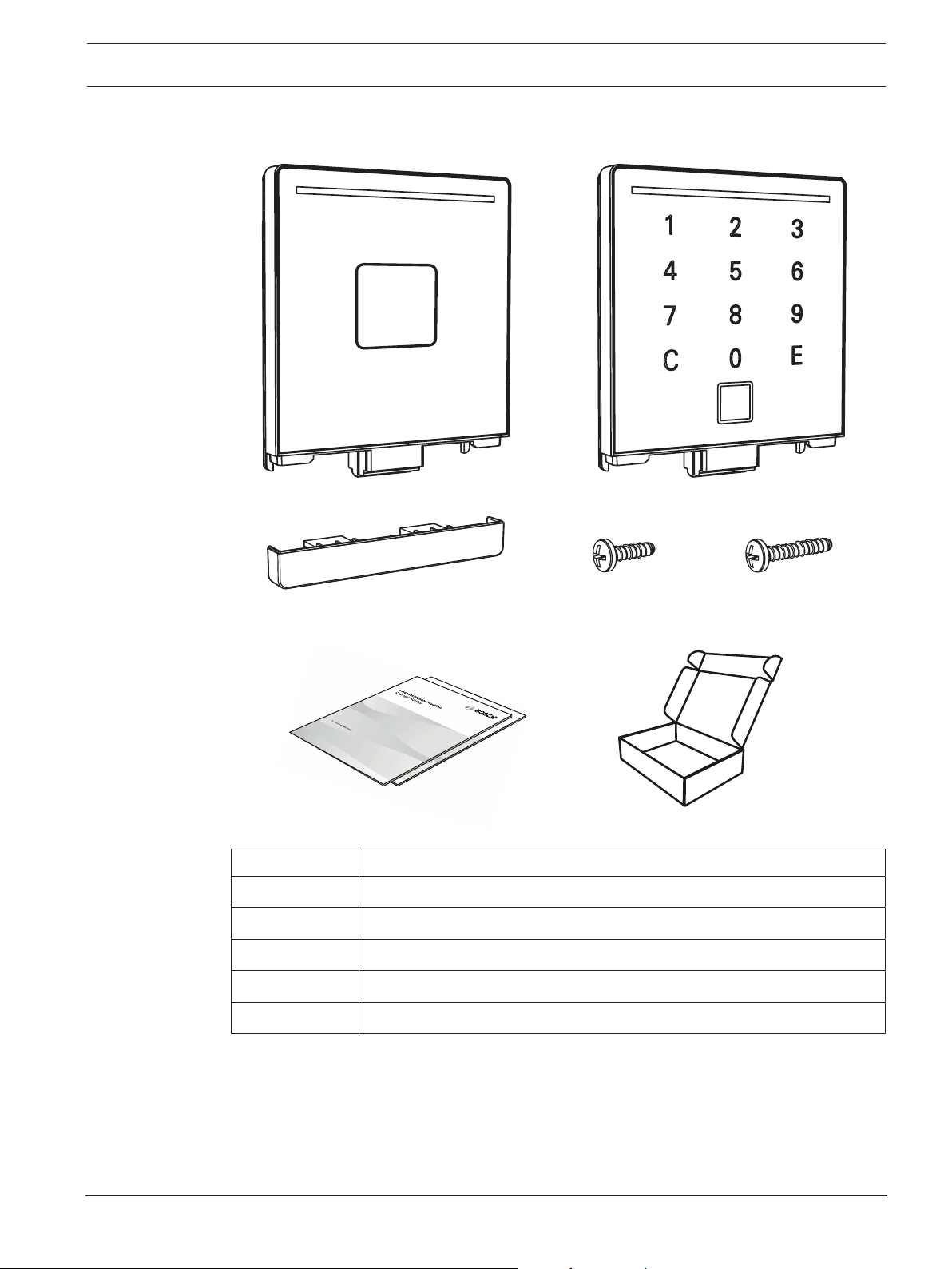
x1 x2 x2
1.4 Components
Bosch Security Systems B.V.
Quantity Component
1 Reader module
1 Locking bar
4 Screws
1 Quick installation guide
2 Safety instructions
Installation manual
2021-02 | 01 | F.01U.389.837
Page 8
8 en | General LECTUS select
1 2
3
4
5
6
7
8
9
C
0
E
1.5 Functional requirements
The LECTUS select reader reads data from contactless RFID credentials and sends the data to
a higher-level control center. This is where the evaluation takes place as to whether a
credential is authorized or not. The result is sent back to the reader, which then provides a
visual and an acoustic signal. Communication between the reader and the control center takes
place via an encrypted RS485 bus.
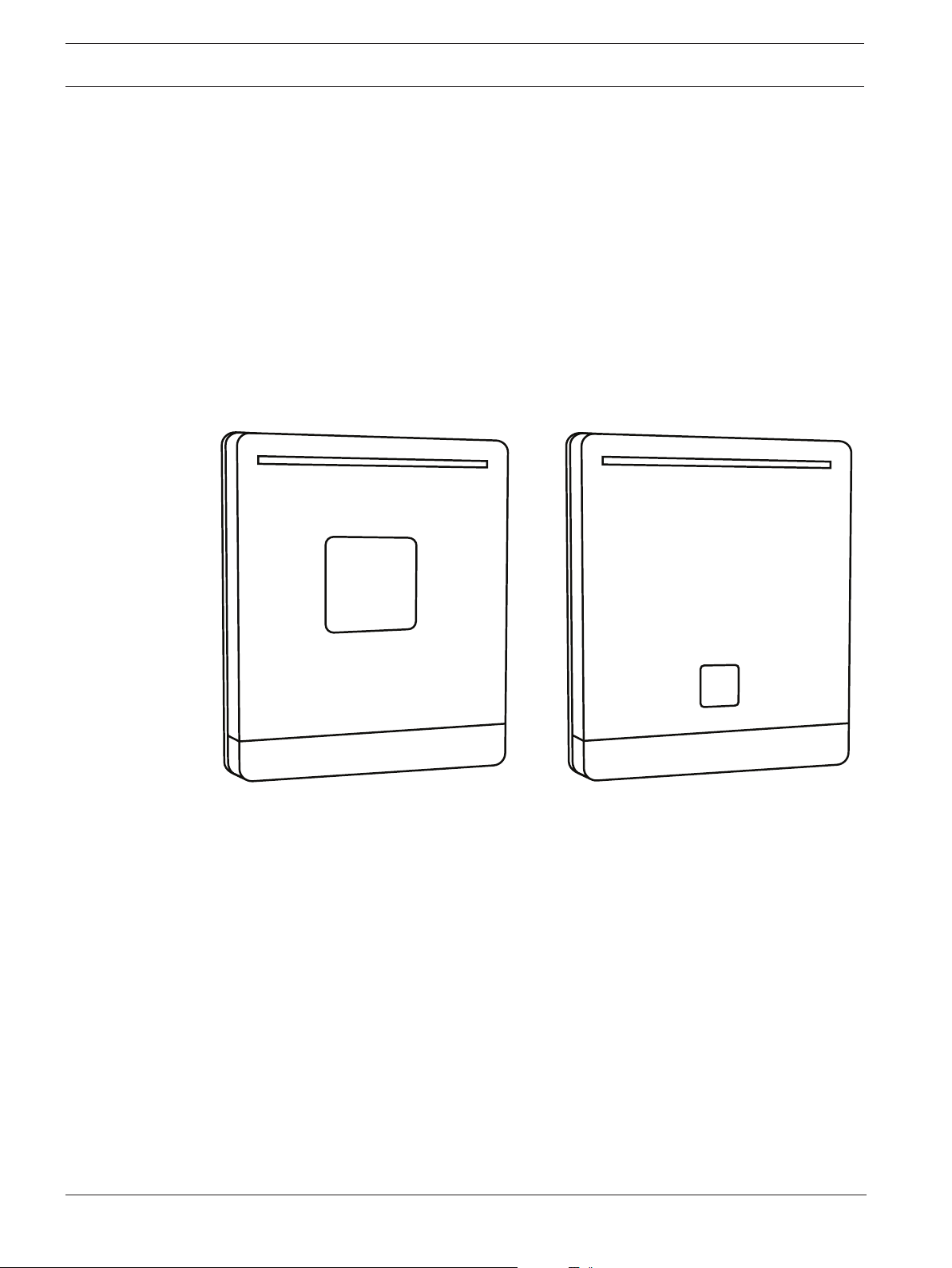
The reader has a compact design and is available in two variants, with and without a keyboard
(each as a flush-mount version). The flush-mounted variant fits into any device box in flushmounted or hollow-wall design according to DIN, with a device screw distance of 60 mm.
The readers have tamper monitoring and tear-off detection (i.e. a sabotage message is
generated if the reader is completely torn from the wall). They are suitable for both indoor and
outdoor use.
Connection type: 8-pin screw / plug-in terminal
2021-02 | 01 | F.01U.389.837
Figure1.2: LECTUS select readers without and with keypad
Installation manual
Bosch Security Systems B.V.
Page 9
LECTUS select General | en 9
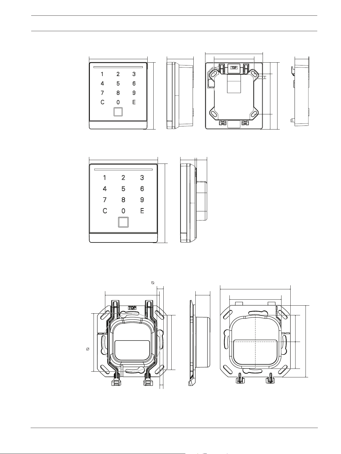
88 mm
41 mm 56 mm
80.4 mm
22 mm 1 mm
101 mm
93.4 mm
56 mm
3.5 mm
16.2 mm
21.2 mm
88 mm 19 mm 16 mm2 mm
101 mm
56 mm
7 mm
3.5 mm
50.5 mm
71.6 mm
14.5 mm
73 mm
26.2 mm25.7 mm
56 mm
60 mm
Surface-mount version
Accessories for surface-mount version: ARA-SELECT-SWA, ARA-SELECT-WWA
Flush-mount version
Wall bracket for flush mounting (part included)
The wall bracket is included in the reader delivery.
Bosch Security Systems B.V.
Installation manual
2021-02 | 01 | F.01U.389.837
Page 10

10 en | General LECTUS select
1.5.1 OSDP
The following readers support OSDP V2 protocol:
Commercial Type Number (CTN) Description
ARD-SELECT-BO Black, OSDP
ARD-SELECT-WO White, OSDP
ARD-SELECT-BOK Black, OSDP, Keypad
ARD-SELECT-WOK White, OSDP, Keypad
OSDP protocol is common within the Bosch Access Control Systems product portfolio.
1.5.2 Phg_crypt
The following readers support phg_crypt protocol:
Commercial Type Number (CTN) Description
ARD-SELECT-BP Black, phg_crypt
ARD-SELECT-WP White, phg_crypt
ARD-SELECT-BPK Black, phg_crypt, Keypad
ARD-SELECT-WPK White, phg_crypt, Keypad
These readers are not compatible with AMC2 controllers. Phg_crypt is a proprietary secure
protocol that can be used in third party installations such as MATRIX.
1.5.3 Firmware overview
LECTUS select Type Firmware
ARD-SELECT-BP, ARDSELECT-BPK, ARD-SELECTWP, ARD-SELECT-WPK
ARD-SELECT-BO, ARDSELECT-BOK, ARD-SELECTWO, ARD-SELECT-WOK
Phg_crypt 68350
OSDP 68435
2021-02 | 01 | F.01U.389.837
Installation manual
Bosch Security Systems B.V.
Page 11

LECTUS select General | en 11
1.6 RFID technology
The LECTUS select readers support the following RFID technology:
– LEGIC prime / Advant
– MIFARE Classic /DESFire / EV 1
The RFID technology that can be used is dependent on the reader configuration and the
reader firmware.
Bosch Security Systems B.V.
Installation manual
2021-02 | 01 | F.01U.389.837
Page 12

12 en | General LECTUS select
i
1.7 Transponder data
The support of the transponder media listed below depends on the respective variant or
reading technology (hardware platform) and the respective reader firmware.
The following non-exhaustive list includes transponder media that is supported by the reader.
RF standard Supported LEGIC
transponders
LEGIC RF standard MIM22, MIM256, MIM1024,
CTC4096-MP410
ISO 14443 A
(also NFC Forum Type 2/4A
Tag *)
ISO 14443 B ***)
(also NFC Forum Type 4B Tag
*)
ISO 15693
(also ISO 18000-3 mode 1)
INSIDE Secure (UID only) according to INSIDE Secure
ATC512-MP, ATC2048-MP,
ATC4096-MP, CTC4096MP410, AFS4096-JP
ATC128-MV, ATC256-MV,
ATC1024-MV
Other supported
transponders **)
according to ISO 14443 part
3/4:
e.g. Infineon SLE, SmartMX
Integrated support of MIFARE
Ultralight, MIFARE Classic,
MIFARE Plus and MIFARE
DESFire NFC peer-to-peer
target
according to ISO 14443 part
4:
e.g. B. InfineonSLE
Selected types, e.g. B. EM
4035, Infineon SRF55VxxP,
Tag-It HFI
*) Passive mode, initiator
**) Access with transparent mode (assigned commands for MIFARE transponders)
***) If transponders according to ISO 14443 B (2001) are used, only one transponder is
allowed in the RF field. This restriction does not apply to transponders according to ISO
14443 B (2008).
****) The SONY FeliCa protocol is supported in accordance with ISO 18092 (6 byte
introduction). Older FeliCa cards with a shorter introduction are not supported.
Notice!
Recommendation when using smart card chips for LEGIC "card in card" solutions:
A suitability and functional test of the corresponding medium should be carried out before
use or if it is planned to be used.
2021-02 | 01 | F.01U.389.837
Installation manual
Bosch Security Systems B.V.
Page 13

LECTUS select General | en 13
i
1.8 Reading distances
The normal reading distance depends on the respective reading system, the installation
environment and the type of data carrier. Direct mounting on metal might reduce the optimal
reading distance.
Reading distances (cm)
Type of transponder media LEGIC prime / advent
Basis 4200M
EC-format Key-fob EC-Format Key-fob
LEGIC MIM 256 3,5 2 - -
LEGIC MIM 1024 4 *) - -
LEGIC ATC2048-MP110 (ISO
14443A)
LEGIC ATC4096-MP310 (ISO
14443A)
LEGIC ATC4096-MP311 (ISO
14443A)
LEGIC AFS4096-JP10/JP11
(ISO 14443A)
LEGIC ATC1024-MV110 (ISO
15693)
Classic 1k - - 3,5 3
Classic 4k - - 4 *)
4,5 2,5 - -
3 1,5 - -
2 1 - -
2 *) - -
6,5 3,5 - -
MIFARE Classic/DESFire
DESFire EV1, 2k / 4k / 8k - - 1 1
Legic CTC4096-MP410 (prime
access)
Legic CTC4096-MP410
(ISO14443 access)
*) Key-fob not available during the test, "AFS4096" not available as key-fob
Note: Not all designs and transponder media were available at the time the distance was
measured.
Notice!
The reading distances listed above are distance ranges measured on the basis of a selection
of transponder media. These measured reading distances are to be regarded as typical guide
values.
If other transponder media are used (chip type, design, size, production process), the
distance ranges may differ and it is recommended to carry out a suitability and functional test
of the respective medium before using or planning to use the reader.
6,5 4 - -
2,5 2 - -
Bosch Security Systems B.V.
Installation manual
2021-02 | 01 | F.01U.389.837
Page 14

14 en | General LECTUS select
Influencing (reducing) the reading distance
The reading distance can be influenced due to different reasons. On the one hand this is
influenced by the medium (i.e. the data carrier) and on the other hand by the ambient
conditions of the antenna and the data carrier.
The following is a list of points that can reduce the reading distance:
– "Shade" or shield the data carrier with metal, such as EC card in your wallet, key fob on
your key ring, etc.
– No optimal coupling, i.e., the antenna surface of the data carrier is perpendicular (90 °) to
the antenna surface of the reader
– Data carrier itself
– key fob (small active antenna surface)
– "bad" response from the data carrier (ID card / key fob)
– combination ID card (e.g. LEGIC® / inductive, MIFARE / inductive etc.)
– Metal in the "active" effective area of the HF field. The transmission energy is attenuated.
This point is particularly relevant when installing the reader components in metal front
panels (including metal columns, etc.).
2021-02 | 01 | F.01U.389.837
Installation manual
Bosch Security Systems B.V.
Page 15

LECTUS select Installation | en 15
2 Installation
2.1 General
When choosing the installation location, please note:
The readers can interfere with each other or be negatively influenced by other systems and
sources of interference. The readers can still disturb each other at a distance of approx. two
to three times the reading distance. High-energy sources of interference in the range of the
modulation and carrier frequencies can also interfere with the transmission.
2.1.1 Mechanical structure of the flush-mount version
2.1.2 Mechanical structure of the surface-mount version
Bosch Security Systems B.V.
Installation manual
2021-02 | 01 | F.01U.389.837
Page 16

16 en | Installation LECTUS select
2.2 Installing data and supply lines
When supplying the reader (especially over longer distances), ensure that the cable crosssection is adequate. Since the power consumption of the individual systems is partially
pulsed, short-term voltage drops cannot be detected with a conventional multimeter (digital
or analog). However, these voltage drops can cause a "POWER-ON-RESET" on the reader
component, which can lead to communication problems.
When dimensioning the power supply and the cable cross-sections of the cabling, the
maximum current consumption must be taken into account. It is essential to ensure that the
input voltage remains constant and corresponds to the technical specifications of the reader.
2021-02 | 01 | F.01U.389.837
Installation manual
Bosch Security Systems B.V.
Page 17

LECTUS select Installation | en 17
65 874321
i
2.3 Assembly preparation
1. Lay the connection cables according to the local conditions and prepare them for
connection.
2. Remove the 8-pin screw / plug-in terminal from the reader module and connect the wires
according to this graphic:
Notice!
The wiring must be carried out in a de-energized state. In other words, the operating voltage
may only be switched on after the reader has been fully installed!
Connection terminal ST1
(8 pin screw / plug terminal, voltage supply / interfaces)
PIN number Description
1 RS485 data “A”
2 RS485 data “B”
3 Do not connect
4 Do not connect
5 Do not connect
6 Do not connect
7 DC- (0V)
8 DC+ (from 8V to 30V)
Bosch Security Systems B.V.
Wire diameter
Stranded wire AWG 28 - 16
Solid wire AWG 28 - 16
Cable stripping length 6 to 7 mm
Installation manual
2021-02 | 01 | F.01U.389.837
Page 18

18 en | Installation LECTUS select
2.4 Assembling the reader
Flush-mount version
1. Use the provided screws to screw the wall bracket onto a DIN device socket with a device
screw distance of 60 mm.
2. Support the reader's tear detection by fixing the perforated tear-off tab with an additional
locking screw.
2021-02 | 01 | F.01U.389.837
Installation manual
Bosch Security Systems B.V.
Page 19

LECTUS select Installation | en 19
Surface-mount version
1. Screw the wall-mount frame to the wall using the screws. The connection cable can be
inserted from above, below or directly from the wall.
2. Tear detection is supported by fixing the upper left screw.
Bosch Security Systems B.V.
Installation manual
2021-02 | 01 | F.01U.389.837
Page 20

20 en | Installation LECTUS select
654321
65 874321
ON WE
2.5 Assembling the reader module
2.5.1 Configuring the reader (DIP switches)
Depending on the firmware function, the DIP switches of the reader module must be set
accordingly.
The reader has 6 DIP switches. Each switch is numbered from 1 to 6.
With the DIP switches it possible to:
– Set the address of the reader
– Set the BUS termination
– Set baud rate for phg_crypt protocol
To change the reader configuration:
1. Power-off the reader.
2. Set the DIP switches correctly.
3. Power-on the reader.
2021-02 | 01 | F.01U.389.837
OSDP protocol
Address 1 2 3 4 5 6 7 8
S1 ON - ON - ON - ON -
S2 - ON ON - - ON ON -
S3 - - - ON ON ON ON -
S4 - - - - - - - ON
S5 Reserved (default - OFF)
S6 Bus terminator resistor (default - OFF)
Installation manual
Bosch Security Systems B.V.
Page 21

LECTUS select Installation | en 21
i
2
1
2
Phg_crypt protocol
Address 1 2 3 4 5 6 7 8
S1 ON - ON - ON - ON -
S2 - ON ON - - ON ON -
S3 - - - ON ON ON ON -
S4 - - - - - - - ON
S5 Adjustment of the baud rate: ON: 19200, OFF 9600
S6 Bus terminator resistor (default - OFF)
Notice!
For the phg_crypt protocol, address 0 is also valid (switches S1 to S4 set to OFF).
2.5.2 Connecting and mounting the reader module
1. Insert the wired connection terminal on the reader module.
2. Place the reader module flat on the wall bracket. Push the connection cable with the
reader module back into the flush-mounted box.
3. Push the attached reader module down until the reader module clicks into place on the
wall bracket.
4. After it has successfully clicked into place, slide the locking bar into the reader module
until it also clicks into place.
– NOTE: A clear click can be heard each time it clicks into place.
Bosch Security Systems B.V.
Installation manual
2021-02 | 01 | F.01U.389.837
Page 22

22 en | Installation LECTUS select
1
2
i
2.5.3 Unmounting the reader module
1. Unlock the locking bar. To do this, use the screwdriver with the blade max. 4 mm wide
into the unlocking openings and press until the lock releases.
2. Pull out the unlocked locking bar and remove it from the reader module.
3. Push the reader module upwards to release it and lift it off forwards.
Notice!
Any changes that are done to the DIP-switches while the power is on are not considered.
2.5.4 Resetting OSDP-key
Upon delivery from the factory, each reader is set to the ‘OSDP installation mode’ to active.
When operating a reader with an AMC using OSDP secure channel, a dedicated generated
encryption key secures operation and prevents the use of the reader in a different site.
Should it be necessary to change the connection to another access modular controller, then
the OSDP-key must be reset.
It is necessary to reset the OSDP-key:
– if readers and/or access modular controllers need to be changed.
– if the reader must be disposed.
1. Disconnect the reader from the socket.
2. Set all DIP-switches to OFF.
3. Connect the reader to the cable for power-up.
– The reader emits a “beep” sound.
– A green LED starts flashing.
4. Disconnect the reader again.
– The reader is now back in ‘OSDP installation mode’.
– The reader can now be used as a new reader.
2021-02 | 01 | F.01U.389.837
Installation manual
Bosch Security Systems B.V.
Page 23

LECTUS select Care instructions | en 23
3 Care instructions
1. Do not operate the reader with sharp objects (rings, fingernails, keys ... etc.)
2. For cleaning, do not use any corrosive or plastic-corrosive liquids such as gasoline,
turpentine, nitrous solution, etc. Harsh detergents can damage or discolor the surface.
3. Do not use cleaning agents with mechanical effects such as scouring milk, scouring
sponge, etc.
4. Only clean the reader with a soft, damp cloth and only use clear water.
Bosch Security Systems B.V.
Installation manual
2021-02 | 01 | F.01U.389.837
Page 24

24 en | Technical specifications LECTUS select
4 Technical specifications
Mechanical
Dimensions (H × W × D mm) 88 × 101 × 35 mm (uninstalled)
88 × 101 × 21 mm (installed)
Dimensions (H × W × D in) 3.5 × 4.0 × 1.4 in (uninstalled)
3.5 × 4.0 × 0.83 in (installed)
Color white/silver | black/silver
Material plastic
Mounting type flush-mounted
Weight (g) 137 g | 139 g
Weight (lb) 0.302 lb | 0.306 g
Environmental
Usage indoor | outdoor
Operating temperature (C) -25 °C to +60 °C
Operating temperature (F) -13 °F to +140 °F
Degree of protection (IEC 60529) IP54
Electrical
Operating voltage (VDC) 8 VDC to 30 VDC
Power consumption (VA) 3.5 VA maximum (2.5 VA typically)
Operation
Audible indication yes
Credential type Card | PIN | Keyfob
Keypad yes | no
Optical indication yes
Software compatibility Building Integration System (BIS)
Access Management System (AMS)
Third-party software
Reading technology LEGIC prime*
1
LEGIC advant
MIFARE Classic*
1
MIFARE DESFire EV1 & EV2
ISO14443A (CSN / UID)*
ISO15693 (CSN / UID)*
1
1
2021-02 | 01 | F.01U.389.837
*1 require specific configuration with OSDP protocol
Installation manual
Bosch Security Systems B.V.
Page 25

LECTUS select Technical specifications | en 25
Connectivity
Reader interfaces RS485
Protocol OSDP
phg_crypt
Bosch Security Systems B.V.
Installation manual
2021-02 | 01 | F.01U.389.837
Page 26

26 en | More information LECTUS select
5 More information
Visit the Bosch online product catalog for the latest technical documentation for this product.
Manufacturing dates
For product manufacturing dates, go to www.boschsecurity.com/datecodes/ and refer to the
serial number on the product label.
Support
Access our support services at www.boschsecurity.com/xc/en/support/.
Bosch Security and Safety Systems offers support in these areas:
– Apps & Tools
– Building Information Modeling
– Commissioning
– Warranty
– Troubleshooting
– Repair & Exchange
– Product Security
Bosch Building Technologies Academy
Visit the Bosch Building Technologies Academy website and have access to training courses,
video tutorials and documents: www.boschsecurity.com/xc/en/support/training/
2021-02 | 01 | F.01U.389.837
Installation manual
Bosch Security Systems B.V.
Page 27

LECTUS select More information | 27
Bosch Security Systems B.V.
Installation manual
2021-02 | 01 | F.01U.389.837
Page 28

28 | More information LECTUS select
2021-02 | 01 | F.01U.389.837
Installation manual
Bosch Security Systems B.V.
Page 29

Page 30

Bosch Security Systems B.V.
Torenallee 49
5617 BA Eindhoven
Netherlands
www.boschsecurity.com
© Bosch Security Systems B.V., 2021
202103121242
 Loading...