

Page 1

P4VMA-M
FCC Inf or m at ion and Copyr ight
This equipment h as bee n te sted and foun d to c omply with the limits of a Class
B digi ta l dev i ce, pu r su ant to Part 15 of t he FCC R ul es. Th es e lim it s ar e de sig ned
to provide reasonable protection against harmful interference in a residential
installation. This equipment genera tes, uses and can r adiate radio frequency
en ergy and, if not installed and used in accor dance wi th the instru ctions, may
cause har mful interf erence to radio communications. Ther e is no guarantee
that interference will not occur in a particular installation.
The vendor makes no representations or warranties with respect to the
con te nt s h ere an d sp ec iall y di sc la im s an y im pl ied w ar r ant ie s of mer c ha nt ab il ity
or fitness for any purpose. Further the vendor rese rves the right to rev ise this
public ati on and to make changes to the contents h er e without ob liga tion to
notify a ny par ty beforehand .
Duplication of this publication, in part or in whole, is not allowed without first
obt aini ng the ve ndor’s approval in wr itin g.
The con te nt of thi s u ser’s m anu al i s subje ct to b e ch an ged with ou t no ti ce an d
we will not be r e sponsible for any mis takes found in this user’s manu a l. All the
brand and produ ct n ame s are trademarks of their re s pe ctive compa n ies.
i
Page 2

Table of Contents
Chapter 1: Introduction.......................................................................1
1.1 Features...............................................................................1
A. Hardware .............................................................................. 1
B. BIOS & Software................................................................... 3
1.2 Package List.........................................................................3
1.3 Layout (Version 7.x) ............................................................. 4
1.4 Components (Version 7.x) ..................................................... 5
Chapter 2: Hardware Installation...................................................6
2.1 Central Processing Unit Installation (CPU).............................6
2.2 FAN Headers....................................................................... 6
2.3 Memory Module Installation ................................................. 7
2.4 Connectors and Slots ............................................................ 8
Chapter 3: Headers & Jumpers Setup..........................................9
3.1 How to Setup Jumpers .......................................................... 9
3.2 Detail Settings......................................................................9
Chapter 4: Useful Help..................................................................12
4.1 Award BIOS Beep Code.......................................................12
4.2 Troubleshooting ..................................................................12
Chapter 5: WarpSpeeder™..............................................................13
5.1 Introduction ........................................................................13
5.2 System Requirement............................................................13
5.3 Installation..........................................................................14
ii
Page 3
P4VMA-M
CHAPTER 1: INTRODUCTION
1.1 FEATURES
AA.. HHaarrddwwaarree
CPU
Supports Socket 478.
Supports Intel Penti um 4 processor.
Supports Intel Celeron/Celeron D processor.
Supports Intel Penti um 4 Northwood/Prescott CPU.
Front Si de Bus at 400/533/800 MHz.
Chipset
North Bridge: VIA PM800.
South Bridge: VIA VT 8237/VT8327R
Dimension
AT X Form Factor: 19.9cm(W) x 24.4cm (L)
Main Memory
Support s up to 2 DDR de vi ces.
Support s 266 /333/400MHz DDR de vi c es.
Maximum memory size i s up to 4GB. (Following tabl e is only for
reference.)
DI MM Socket
Location
DI MM 1 64MB/128MB/256MB/512MB/1GB/2GB * 1
DI MM 2 64MB/128MB/256MB/512MB/1GB/2GB * 1
DDR Module
To t a l Me m or y
Size
Max i s 4G B.
Super I/ O
Chip: IT E IT8705
Provides the most commonly used legacy super I/O
functionality.
Environment Control initiatives:
¾ H/W Monitor,
¾ Fan Speed Controller (optional),
¾ ITE “Smart Gu ardian” f unction .
10/100 LAN PHY
Chip: VT6103L
Supports 10/100 Mb/s auto-negotiation operation.
Half /Full duplex capabilit y.
Supports ACPI, PCI power management.
1
Page 4

P4VMA-M
Slot
3 PCI bus master slots.
1 AG P 4x/8x co m patib l e slot.
1 CNR sl ot .
Serial ATA
Supports 2 serial ATA (SATA) ports.
Data tra n sfer rates up to 150 M B /s.
Complaints with SATA Versi on 1.0 specification.
Onboard I DE
Support 4 IDE d isk dr ives.
Supports PIO mode 0~4, Bus M aster, and Ul tra DMA
33/66/100/133 function.
Onboard A D’9 7 So und Codec
Chip: ALC655
Support 6 channels.
Supports S/PDIF ou t function .
Compliant with AC’97 Version 2.3 specification.
Fr o nt Side On-board Per ipherals
1 CNR sl ot supports n etworking fa cili tie s.
1 front panel header supports front panel facili ties.
1 S/PDIF out connector supports digital out function.
1 CD-in connector supports 1 CD-ROM audi o-in device.
1 front audio header supports front panel audio function.
1 chassis open header supports PC case-opened warning
function.
1 Floppy port supports 2 FDD with 360K, 720K, 1.2M, 1.44M
and 2.88M bytes.
2 USB headers support 4 USB 2.0 ports.
2 IDE connectors support 4 hard di sk devices.
2 serial ATA connectors support 2 SATA devices.
2
Page 5
P4VMA-M
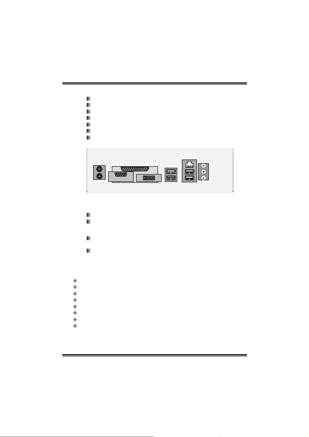
Rear Side Conne ctors
4 USB 2.0 ports.
1 VGA port.
1 serial port.
1 parallel port.
1 RJ- 45 LA N jac k .
1 PS/2 M ouse & Keyboard port.
1 vertical audio port including 1 li ne-in connector, 1 speaker out
conn ec tor, and 1 MIC in connec t or.
JKBMS1
PS/2
PS/2
Mouse
Mouse
PS/2
PS/2
Keyboard
Keyboard
COM1
COM1
JCOM1
JPRNT1
Parallel
Parallel
VGA1
VGA1
JVGA1
BB.. BBIIOOSS && SSooffttwwaarree
BIOS
Award legal BIOS.
Supports APM1. 2 , AC PI , an d USB fu nctio ns.
Software
Supports 9th TouchTM, Fl asherTM, WinFlasherTM, Bo ot b lockerTM,
and WarpspeederTM.
Offers th e highest performance fo r Windo ws 98 , Windo ws NT,
Windows 2000, Windows ME, Windows XP, Red-Hat Linux, and
UNIX se ries.
JUSBLAN1
LAN
LAN
JUSB1
US B x2 USB x 2
US B x2 USB x 2
JAUDIO1
Line In
Line In
Speaker Out
Speaker Out
Mic In
Mic In
1.2 PACKAGE LIST
FDD cable x1
HDD ca ble x1
User’s M anual x1
Fu lly Se tu p Driver CD x1
USB 2.0 cable x1 (optional)
Serial ATA cable x2 (opti onal)
S/ PD IF out cable x 1 (optional)
Rear I/O p anel for ATX case x1 (o p tio nal)
3
Page 6
P4VMA-M
A
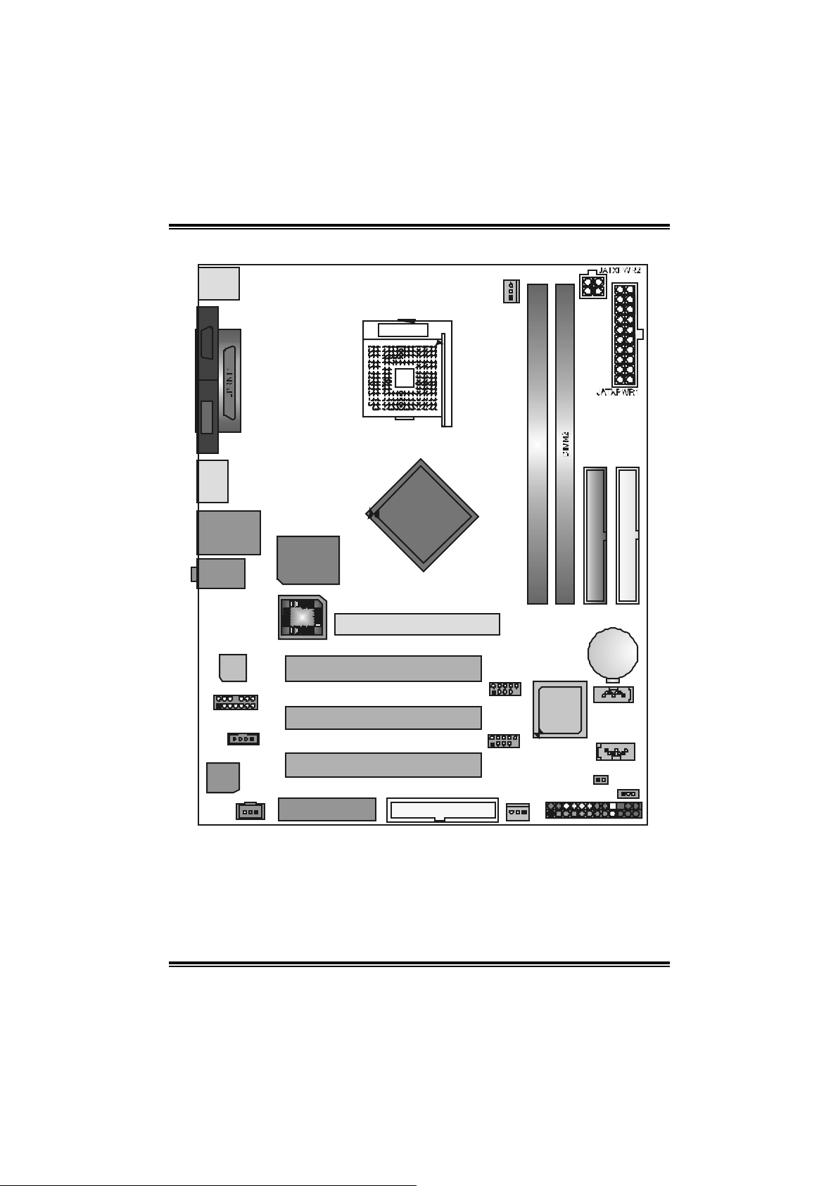
1.3 LA YOUT (VERS ION 7.X)
JKBMS1
CPU1
JCOM1JVGA1
JUSB1
JUSBLAN1
Super I/ O
JAUDI O
LAN
PH Y
JAUDI O1
1
CODEC
CODEC
JSPD IFO1
JCDIN1
IT 8705
BIOS
PCI1
14
PCI2
1
PCI3
1
CNR1
Note: ■ represents the 1st pin.
Socket 478
PM 800
GP1
FD D1
1
JC FA N1
JUSB3
9
1
JUSB4
19
JSFAN1
1
DIMM1
VT 8237
or
VT8237R
JPANEL1
1
IDE1
BAT1
JSATA1
JSATA2
1
JCI1
1
IDE2
1
JCMOS1
1
242
23
4
Page 7
P4VMA-M
G
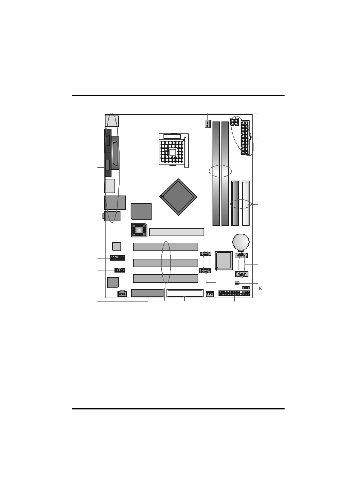
1.4 COMPONENTS (VERSION 7.X)
CPU1
Soc ket 47 8
R
Q
A
Supe r I /O
IT 8705
BI OS
LAN
PHY
B
C
CODEC
CODEC
D
E
Rear (back) side connec tors.
A.
JAU DIOIN1: Front s ide audio out
B.
header.
JCDIN1: CD- In connec tor.
C.
JSPD IF1: Digital Audio c onnector.
D.
CN R1 : Co mmun i catio n Ne twor k Ri se r
E.
slot.
PCI 1~3: Peripheral C om ponent
F.
Int erc onnect slot s.
FDD1: Floppy D isk connec t or.
G.
JSF AN 1: Sy stem Fan header.
H.
JUSB3~4: Fron t side USB header s.
I.
P
PM 800
O
N
BA T 1
VT 8237
or
VT823 7R
FD D 1
F
J.
K.
L.
M.
N.
O.
P.
Q.
HI
JPAN EL1: Front Panel headers.
JCMOS1: Clear CMOS header.
JC I 1: C hassis open header.
JSATA1~2: Serial ATA c onnectors.
AGP1: Accelerat ed Graphics Port s lot.
ID E1~2: Hard Disk connec t ors.
DI MM1~2: DDR DIMM m odules.
JATXPW R 1~2: ATX Power Source
J
M
L
connectors.
JCFAN 1: CPU F an header.
R.
5
Page 8
P4VMA-M
CHAPTER 2: HARDWARE INSTALLATION
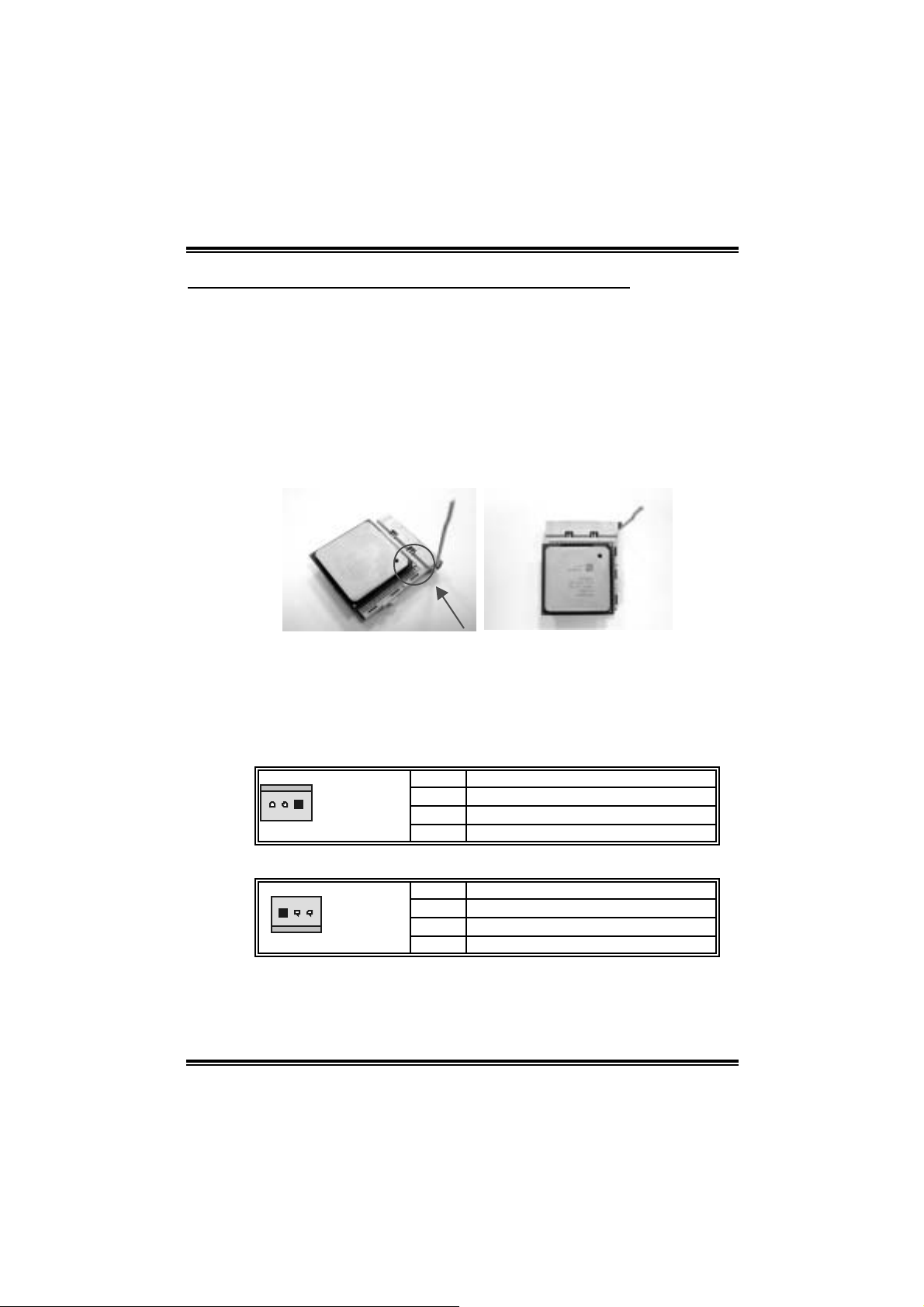
2.1 CENTRAL PROCESSING UNIT INSTALLAT ION (CPU)
Step 1: Pull the lever si deways away from the socket and then raise the
lever up to a 90-degree angle.
Step 2: Look for the white dot/cut edge. The white dot/cut edge should
point ward s the lever pi vot . T he CPU will fi t only in the c orre c t
orientation.
Step 3: Hold the CPU down firmly, and then close the lever to com plete
the i nstal la ti on.
Step 4: Put the CPU Fan on the CPU and buckl e it. Connect the CPU FAN
power cable to the JCFAN1. This compl etes the i nstallation.
2.2 FAN HEADERS
These fan headers support cooling-fans bui lt in the computer. The fan
wir in g and plu g may be diff er ent accordi ng to the fa n ma nufactur er.
Connect the fan cable to the connector while matching the black wire to
pin#1.
CPU FAN Header: JCFA N1
Pin Assignment
1
JCFAN1
System Fan Header: JSFAN1
1
JSFAN1
Note: The JCFAN1 and JSFAN1 support 3-pin head connector. When
connecting with wi res onto connectors, pl ease note that the red wire is the
positive and should be connected to pin#2, and the black wire i s Ground
and should be c onnect ed to GN D .
1 Ground
2 +12V
3 FAN RPM rate sense
Pin Assignment
1 Ground
2 +12V
3 FAN RPM rate sense
6
Page 9
P4VMA-M
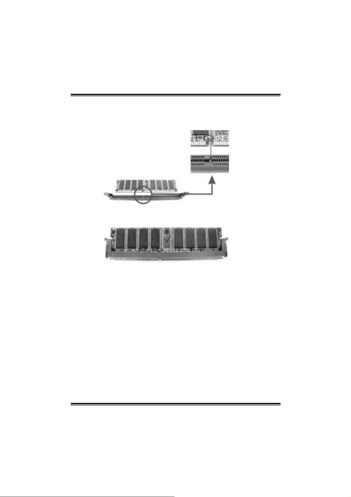
2.3 MEMORY MODULE INSTALLATION
1. Unlock a DIMM slot by pressing the retaini ng clips outward. Ali gn a
DIMM on the slot such that the notch on the DIMM matches the
break on the Sl ot.
2. Insert the DIMM vertically and fi rml y into the slot until the retaining
chip snap back in place and the DIM M is properl y seated.
Note:
To assur e th e syste m safe ty, if you need to chan g e DDR m odu le s, fir stly,
please unplug the 20-pin power cable with the power connector, an d
the n y ou can ch ang e the m odu le s. A fter war ds, p lug i n the cable th e
power connector again, and finally you can boot up the system.
7
Page 10

P4VMA-M
2.4 CONNECTO RS AND SLOTS
FFDDDD11:: FFllooppppyy DDiisskk CCoonnnneeccttoorr
The motherboard provides a standard floppy disk connector that
s uppor t s 360 K, 720 K , 1.2 M, 1. 4 4 M a nd 2.88M f lo ppy d is k types. Th is
connector supports the provided floppy drive ribbon cables.
IIDDEE11~~22:: HHaarrdd DDiisskk CCoonnnneeccttoorrss
The motherboard has a 32-bi t Enhanced PCI IDE Controller that
provides PIO Mode 0~5, Bus Master, and Ultra DMA 33/ 66/ 100
fun c tio nality. It has two HDD connectors IDE 1 (p rimary) and IDE2
(secondary).
The IDE connectors can connect a master and a slave drive, so you can
connect up to four hard disk drives. The fi rst hard drive should always be
connected to IDE1.
PPCCII11~~33:: PPeerriipphheerraall CCoommppoonneenntt IInntteerrccoonnnneecctt SSlloottss
This m otherboard is equipped with 5 standard PCI slots. PCI stands for
Peripheral Com ponent Interconnect, and i t is a bus standard for
expansion cards. Thi s PCI sl ot is designated as 32 bits.
AAGGPP11:: AAcccceelleerraatteedd GGrraapphhiiccss PPoorrtt SSlloott
You r mon ito r will atta c h di rectl y to that vid eo ca rd. This mothe rbo ard
supports video cards for PCI slots, but it i s also equipped wi th an
Accelerated Graphics Port (AGP). An AGP card will take advantage of
AGP technol ogy for improved video effi ciency and performance,
especially wi th 3D graphi cs.
CCNNRR11:: CCoommmmuunniiccaattiioonn NNeettwwoorrkk RRiisseerr SSlloott
The CNR specifica tion is an op en Ind ustry Standar d Ar c hi tec t ur e, and it
defines a hardware scalable riser card i nterface, which supports modem
only.
SSeerriiaall AATTAA CCoonnnneeccttoorr:: JJSSAATTAA11~~22
The motherboard has a PCI to SATA Controller with 2 channels SATA
interface, it satisfies the SATA 1.0 spec and wi th transfer rate of 1.5Gb/s.
Pin Assignment Pin Assignment
17
JSATA1~2
1 Ground 2 TX+
3 TX- 4 Ground
5 RX- 6 RX+
7 Ground
8
Page 11
P4VMA-M
CHAPTER 3: HE ADERS & JUMPERS SETUP
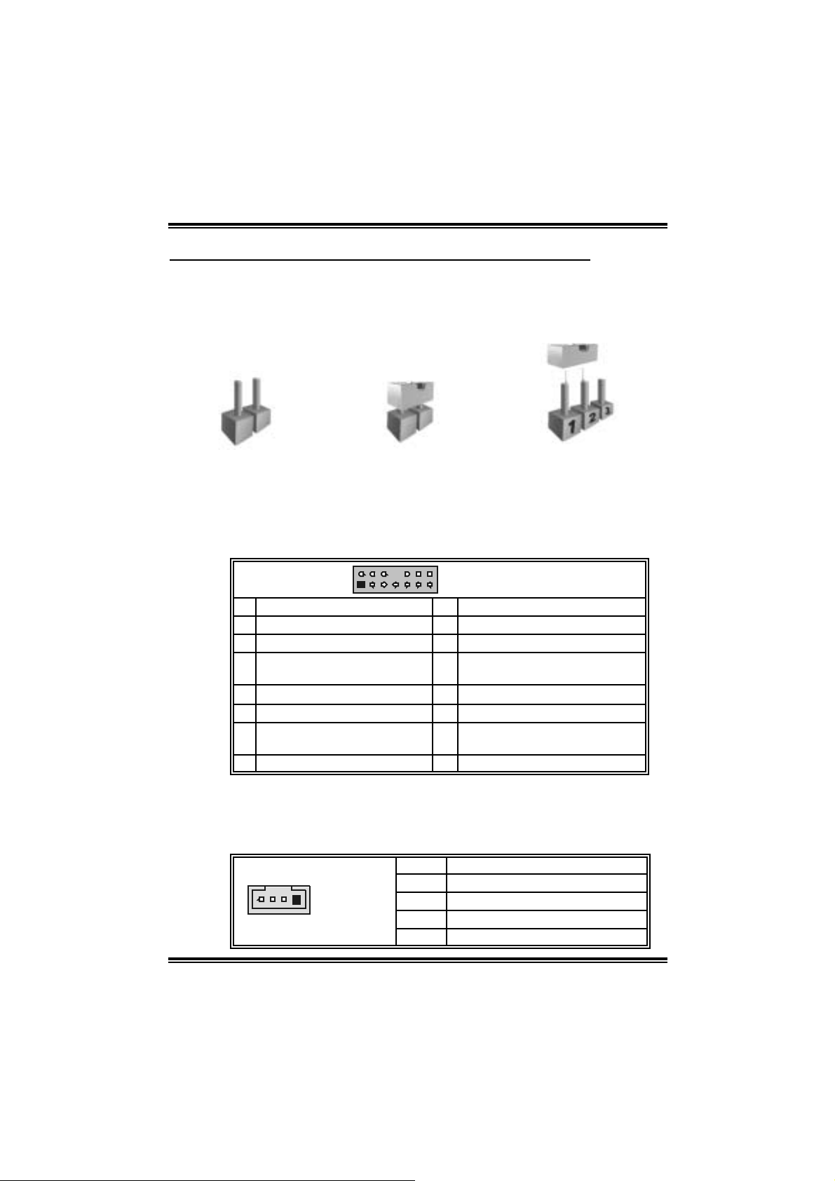
3.1 HOW TO SETUP JUMPERS
The illustration shows how to set up jumpers. When the jumper cap is
placed on pins, the jumper is “cl ose”, if not, that means the j umper is
“open”.
Pin opened Pin closed Pin1-2 closed
3.2 DETAIL SETTINGS
JAUDIO1: Front Panel Audio Header
This header allows user to connect the front audio out put cable wi th the
PC front panel. It will disab le the o utput on ba c k pan el audio co nn ecto rs.
2
1
Pin Assign men t Pin Assig n men t
1 Mic in/center 2 Ground
3 Mic power/Bass 4 Audio power
Right line out/ Speak er out
5
Right
7 Reserv ed 8 Key
9 Left line out/ Speak er out Left 10 Left line out/ Speak er out Left
Right line in/R ear speaker
11
Right
13 Lef t line in/Rear s peak er Left 14 Left line in/R ear speaker Left
JCDI N1 : C D-ROM A ud io -in Co n ne cto r
This connector allows user to connect the audio source from the veriaty
devices, like CD-ROM, DVD-ROM, PCI so und ca rd, PCI T V turner card
etc..
1
JCDIN1
14
13
JAUDIO1
6 Right line out/ Speak er out R ight
12 R ight line in/R ear speaker Right
Pin Assignment
1 Left channel input
2 Ground
3 Ground
4 Right channel input
9
Page 12
P4VMA-M
JSP DI F _ OU T 1 : Dig ita l A u dio Conn ector (op tio n al)
This connector allows user to connect the PCI bracket SPDIF output
header.
Pin Assignment
1
JSPDIF_OUT1
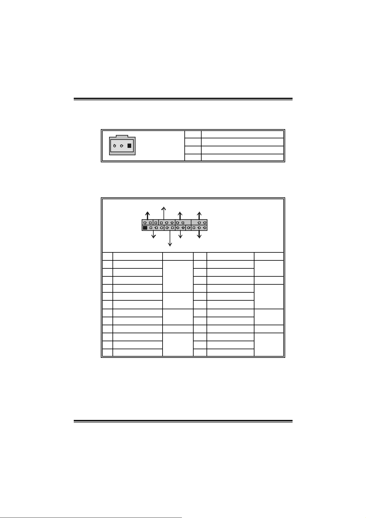
JPANEL1: F ront Panel Header
This 24-pin connector includes Power-on, Reset, HDD LED, Power LED,
Sleep button, speaker and IrDA Connection. It allows user to connect
the PC case’s front panel switch functions.
PWR_LED
SLP
On/Off IR
++
2
1
Pin Assignment Function Pin Assignment Function
1 +5V 2 Sleep control
3 N/A 4 Ground
5 N/A 6 N/A N/A
7 Speaker
9 HDD LED (+) 10 Power LED (+)
11 HEE LED (-)
13 Ground 14 Power button
15 Reset control
17 N/A 18 Key
19 N/A 20 Key
21 +5V 22 Ground
23 IRTX
+--
SPK
HLED
Speaker
Connector
Hard drive
LED
Reset
button
IrDA
Connector
1 +5V
2 SPDIF_OUT
3 Ground
24
23
RST
IR
8 Power LED (+)
12 Power LED (-)
16 Ground
24 IRRX
JPANEL1
Sleep
button
Power LED
Power-on
button
IrDA
Connector
10
Page 13
P4VMA-M
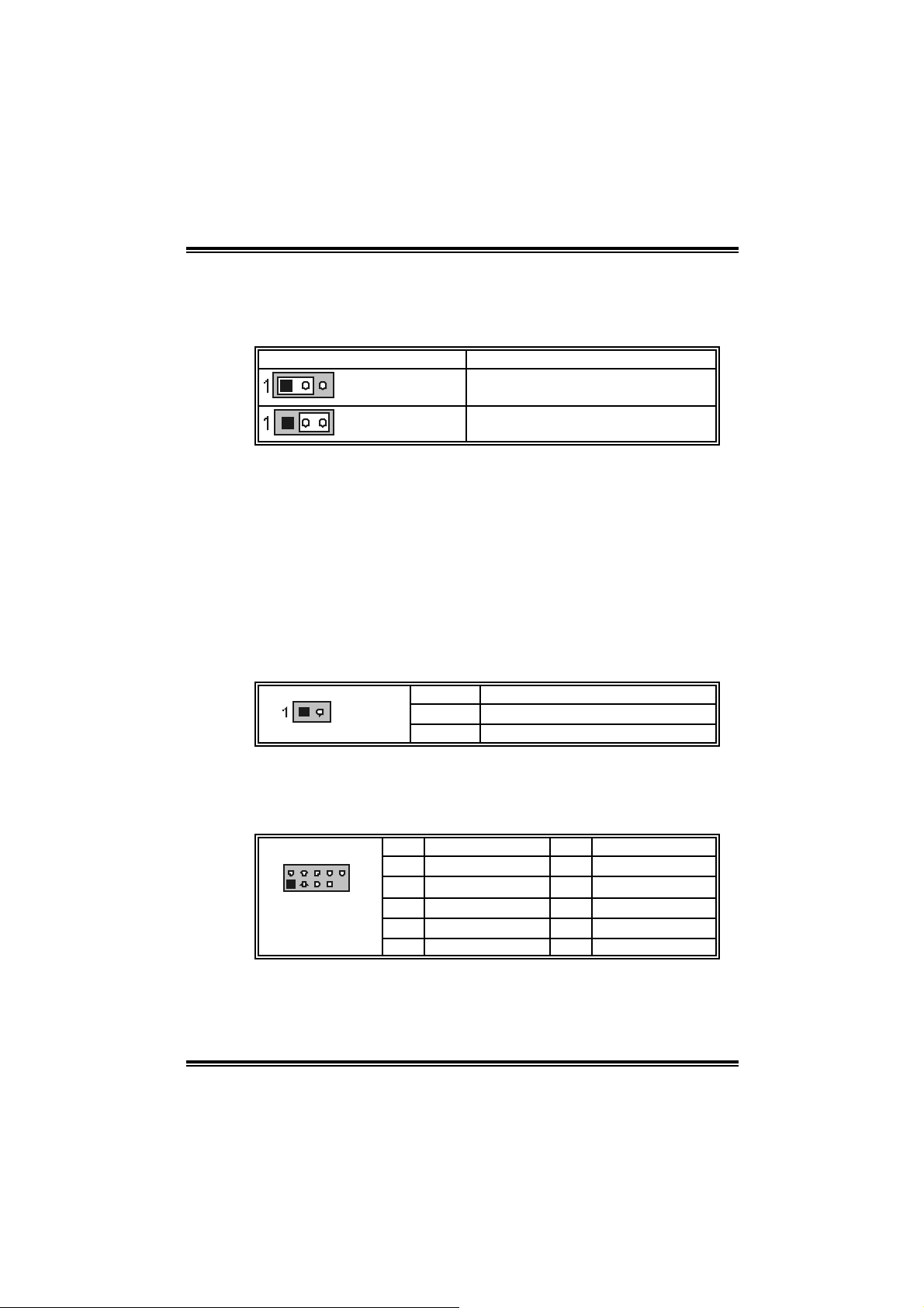
JCMOS1: Close CMOS Header
By placi ng the jumper on pin2-3, it allows user to restore the BIOS safe
setting and the CMOS data, please carefully follow the procedures to
avo id da ma ging th e mot her b oar d.
JCMOS1 Assignment
Pin 1-2 close
Pin 2-3 close
※ Clear CMOS Procedures:
1. Remove AC power line.
2. Set the jumper to “Pin 2-3 close”.
3. Wai t for f i ve seconds.
4. Set the jumper to “Pin 1-2 close”.
5. Power on the AC.
6. Reset your desired password or clear the CM OS data.
JCI1: Case Open Header
T his connecto r allows syste m to monitor PC case open statu s. If th e
signal has been tri ggered, i t will record to the CMOS and show the
message on next boot-up.
Pin Assignment
JCI1
Norm al Operation (D ef ault).
Clear CMOS data.
1 Cas e open signal
2 Ground
JUSB3/JU SB4: F ro nt USB Headers
This m otherboard provides 2 USB 2.0 headers, which all ows user to
connect additional USB cable on the PC front panel, and also can be
connected wi th internal USB devi ces, like USB card reader.
Pin Assignment Pin Assignment
210
1
JUSB3/JUSB4
1 +5V (f used) 2 +5V (f used)
3 USB- 4 USB-
5 USB+ 6 USB+
7 Ground 8 Ground
9 Key 10 NC
11
Page 14

P4VMA-M
n
d
CHAPTER 4: USEFUL HELP
4.1 AWARD BIOS BEEP CODE
Beep Meaning
One long beep f ollowed by t wo s hort
beeps
High-low siren sound
One Short beep when system
boot-up
Long beeps every other second No DRAM detected or inst all
4.2 TROUBLESH OOTING
Video card not f ound or video c ard
mem ory bad
CPU overheated, sys t em will shut down
automatically
No error found during POST
Problems Solution
1. No power to the system at all
Power light don’t illuminat e, f an
inside power s upply does not t ur
on.
2. Indic at or light on key board does
not t urn on.
Sys t em inoperat iv e. Key board lights
are on, power indic at or lights are lit,
and hard driv e is spinning.
Sys t em does not boot from hard dis k
drive, can be booted fro m CD- ROM
drive.
System only boots f rom CD-ROM.
Hard disk can be read and
applicat ions can be used but boot ing
from hard disk is im possible.
Screen m essage say s “Invalid
Conf igurat ion” or “CMOS Failure.”
Cannot boot sys t em af t er inst alling
sec ond hard drive.
1. Make sure power c able is s ec urely
plugged in.
2. Replace cable.
3. Contact technical support.
Us ing even pres s ure on both ends of
the DIMM, press down firm ly unt il the
module s naps int o place.
1. Chec k cable running from disk t o
disk controller board. Make sure
both ends are s ec urely plugged in;
chec k the drive type in the standar
CMOS setup.
2. Back ing up the hard drive is
ext rem ely im port ant. All hard disks
are capable of break ing down at
any time.
Back up data and applications f iles.
Ref orm at t he hard drive. Re-install
applicat ions and dat a using bac k up
disks.
Rev iew system’s equipm ent. Make sure
correc t inf ormat ion is in setup.
1. Set master/slave jumpers correctly.
2. Run SETUP program and s elect
correc t driv e types. C all the drive
manuf acturers f or compatibility with
other driv es.
12
Page 15

P4VMA-M
CHAPTER 5: WARPSPEEDER™
5.1 INTRODUCTION
[WarpSpeeder™], a new powerful control uti lity, features three
user-friendly functions including Overclock Manager, Overvol tage
Manager, and Hardware Monitor.
With the Overclock Manager, users can easi ly adjust the frequency they
prefer or they can get the best CPU performance with just one click. The
Overvoltage Manager, on the other hand, helps to power up CPU core
vol tage an d Me mor y v ol ta ge. Th e co ol Har dw are Mo nit or s mar tly in d icates
the tem peratures, voltage and CPU fan speed as well as the chi pset
information. Also, in the About panel, you can get detail descripti ons about
BIOS m odel and chipsets. In addition, the frequency status of CPU,
memory, AGP and PCI along with the CPU speed are synchronically
s how n on our ma i n p an el .
Moreover, to protect users' computer systems if the setting i s not
appropriate when testing and results in system fail or hang,
[WarpSpeeder™] technology assures the sy stem stability by automatically
rebooting the com puter and then restart to a speed that is either the
original system speed or a suitable one.
5.2 SYSTEM REQUIREMENT
OS Support: Windows 98 SE, Windows M e, Windows 2000, Windows XP
DirectX: DirectX 8.1 or above. (T he Windows XP operating system
incl udes DirectX 8.1. If you use Windows XP, you do not need to instal l
Dir ec tX 8.1.)
13
Page 16
P4VMA-M
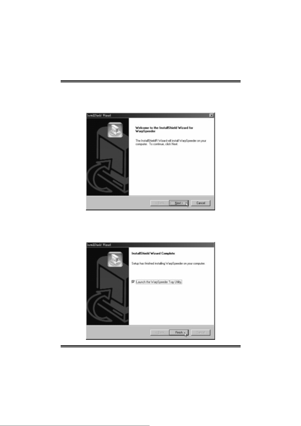
5.3 INST ALL ATION
1. Execute the setup executi on file, and then the following dialog will pop
up. Please click “Next” button and follow the default procedure to
install.
2. When you see the following dialog in setup procedure, it means setup
is completed. If the “Launch the WarpSpeeder Tray Utility” checkbox
is che c ked, th e Tray Icon utili ty and [ WarpSpeed er™] util ity will b e
automatically and immediately l aunched after you click “Finish”
button.
14
Page 17

P4VMA-M
Usage:
The following figures are just only for reference, the screen printed in
this user manual will chan ge ac c ording to your motherboard on ha nd.
[[WWaarrppSSppeeeeddeerr™™]] iinncclluuddeess 11 ttrraayy iiccoonn aanndd 55 ppaanneellss::
1. Tray Icon:
Whenever the Tray Icon utility i s launched, it will di splay a little tra y
icon on the right side of Windows Taskbar.
This utility is responsible for conveni ently invoking [WarpSpeeder™]
Utility. You can use the mouse by clicking the left button in order to
invoke [WarpSpeeder™] directly from the little tray icon or you can
right-click the little tray icon to pop up a popup menu as following
figure. The “Launch Utility” i tem in the popup menu has the same
fun c tio n a s mouse lef t-click on tray icon and “Exit” item will cl ose
T ray Icon utility if selecte d.
2. Main Panel
If y ou click the tray icon, [WarpSpeeder™] utility will be invoked .
Please refer to the follo wing fi gure; the utility’s first window you will
see is Main Panel.
15
Page 18

P4VMA-M
Main Panel contains features as follows:
a. Displ ay the CPU Speed, CPU external clock, Memory clock,
AGP clock, and PCI clock inform ation.
b. Contains About, Voltage, Overclock, and Hardware M onitor
Buttons for invoking respective panels.
c. W ith a user - fr ie nd ly Status An im ation, it c an r epr esent 3
overclock percentage stages:
Man walking→overcl ock percentage from 100% ~ 110 %
Panther runni ng→overclock percentage from 110% ~ 120%
Ca r rac ing→overclock percentage from 120% ~ above
16
Page 19

P4VMA-M
3. Voltage Panel
Click the Volta ge button in Main Pa nel, the button will be hig hligh ted
and the Vol ta ge Pa nel will slid e out to up as the f ollowing figure.
In this panel, you can decide to increase CPU core vol tage and
Memory vo ltage or not. The d efault se tting is “No”. If you wa n t to get
the best performance of overcl ocking, we recommend you click the
option “Yes”.
17
Page 20

P4VMA-M
4. Overclock Panel
Click the O vercloc k button in Main Panel, the b utto n will be hig hlighted
and the Overclock Panel will slide out to left as the following fi gure.
Overclock Panel co ntain s the these features:
a. “–3M Hz button”, “-1MHz button”, “+1MHz button”, and “+3MHz
button”: provi de user the ability to do real-time overclock
adj ustment.
Warning:
Manually overclock is pot entially dangerous, especially when t he
overclocking percentage is over 110 %. W e strongly rec ommend you
verify every speed y ou overclock by c lick the Verify button. Or, you c an
just click Aut o overc lock button and let [WarpSpeeder™] aut om atically
gets the best result for y ou.
b. “Recovery Dialog button”: Pop up the following dialog. Let user
select a restoring way if system need to do a fail-safe reboot.
18
Page 21

P4VMA-M
c. “Auto-overclock button”: User can click thi s button and
[Wa rpS peeder™] will set th e b est and stable pe rf orma nce and
frequency automatically. [WarpSpeeder™] utili ty will execute a
series of te stin g until syst em f ail. Then syste m will do fail-safe
reboot by usi ng Watchdog function. After reboot, the
[WarpSpeeder™] utility will restore to the hardware defaul t
setting or load the veri fied best and stable frequency according
to the Reco very Dialog ’s setti ng.
d. “Verify button”: User can click thi s button and [WarpSpeeder™]
will proceed a testing for current frequency. If the testing is ok,
then the current fre quency will be saved in to system registry. If
the testing fail, system wil l do a fail-safe rebooting. After reboot,
the [WarpSpeeder™] utility will restore to the hard ware defau lt
setting or load the veri fied best and stable frequency according
to the Reco very Dialog ’s setti ng.
Note:
Becaus e the t esting programs, inv ok ed in Auto-overclock and Verify,
include D irectDraw, D irect3D and D irectShow t ests, the DirectX 8.1 or
newer runtime library is required. And please m ak e sure y our display
card’s color depth is High color (16 bit) or True color( 24/32 bit ) that is
required for Direct3D rendering.
19
Page 22

P4VMA-M
5. Hardware Monitor Panel
Click the Hard ware Moni to r bu tton in Ma in Pane l, the button will be
highlighted and the Hardware Monitor panel will slide out to left as
the fo l lowing fig ur e.
In this panel, you can get the real-time status inform ation of your
system. The informa tio n will be ref reshed every 1 second.
20
Page 23

P4VMA-M
6. About P ane l
Click the “about” button in M ain Panel, the button will be highlighted
and th e A b out Pa nel will s l id e out t o up as the fo l lowing f ig ur e.
In this panel, you can get model name and detail inform ation in hints
of all the chipset that are related to overclocking. You can al so get
the mainboard’s BIOS model and the Version number of
[WarpSpeeder™] utility.
Note:
Because the overclock, overvoltage, and hardware monitor features are
controlled by several separate chipset, [WarpSpeeder™] divide these
features to separate panels. If one chipset i s not on board, the
correlat ive button i n M ain panel will be disabled, but will not inte r fer e
other panels’ functi ons. T his property can make [WarpSpeeder™] utili ty
more robust.
21
Page 24

P4VMA-M
8/27, 2004
22
Page 25

P4VMA-M BIOS Setup
BIOS Setup........................................................................................1
1 Main Menu.....................................................................................................3
2 Standard CMOS Features ..............................................................................6
3 Advanced BIOS Features............................................................................... 9
4 Advanced Chipset Features.......................................................................... 13
5 Integrated Peripherals ..................................................................................17
6 Power Management Setup ........................................................................... 21
7 PnP/PCI Configurations............................................................................... 26
8 PC Health Status ..........................................................................................29
9 Frequency Control .......................................................................................30
i
Page 26

BIOS Setup
Introduction
T his manual discussed Awa rd™ Set up program built into the ROM BIO S. Th e Setu p
program allows users to modify the basic system configuration. This special information is
th en stor ed in batte ry-back ed RAM so th at it retain s the Setu p infor mation when th e power
is turned off.
T he Award BIOS™ in stalled in y our co mputer system’ s ROM (Read Only Me mory ) is a
custom version of an industry standard BIOS. This means that it supports Intel
processors input/output system. The BIOS provides critical low- level support for standard
devices such as disk drives and seria l and parallel ports.
Addin g important has customized the Award BIOS™, but nonstandard, features such as
virus and password protection as well as special support for detailed f ine-tuning of the
chipset controlling the entire system.
The rest of this manual is intended to guide you through the process of configuring your
system using Setup.
Plug and Play Support
These AWARD BIOS supports the Plug and Play Version 1.0A specification. ESCD
(Extended System Configuration Data) write is supported.
EPA Green PC Support
This AWARD BIOS supports Version 1.03 of the EPA Green PC specification.
APM Support
These AWARD BIOS supports Version 1.1&1.2 of the Advanced P ower Management
(APM) specification. Power management features are implemented via the System
Management Interrupt (SMI). Sleep and Suspend power management modes are supported.
Power to the hard disk drives and video monitors can be managed by this AWARD BIOS.
TM
1
Page 27

PCI Bus Support
This AW ARD BIOS also supports Version 2.1 of the Intel PCI (Peripheral Component
Interconnect) local bus specificat ion.
DRAM Support
SDRAM (Synchronous DRAM) are supported.
Supported CPUs
This AWARD BIOS supports the IntelTM CPU.
Using Setup
In general, you use the arrow keys to highlight items, press <Enter> to select, use the
<PgUp> and <PgDn> keys to change entries, press <F1> for help and press <Esc> to quit.
The following tab le provides more detail about how to navigate in the Setup program by
using the keyboard.
Keystroke Function
Up arrow Move to previo us ite m
Down arrow Move to next item
Left arrow Move to the item on the left (me nu bar)
Right arro w Move to the item on the right (menu bar)
Esc Main Menu: Quit without saving changes
Move Ente r Move to the ite m yo u des ired
PgUp k e y Increase the nu mer ic value or make changes
PgDn k ey Decrease the numeric value or make changes
+ K ey Inc rease the numeric value or make c hanges
- Key Decrease the numeric value or make changes
F1 k ey Genera l help on Setup na vigat io n ke ys
F5 k ey Load pre vious va lues fro m CMOS
F6 key Load the fail-safe de faults from BIOS defa ult tab le
F7 key Load the optimized d efa ults
F10 key Save all the CMOS change s and exit
Sub menus: Exit Current page to the next higher leve l menu
2
Page 28

1 Main Menu
Once you enter Award BIOS™ CMOS Setup Utility, the Main Menu will appear on the
screen. The Main Menu allows you to select from several setup functions. Use the arrow
keys to select among the items and press <Enter> to accept and enter the sub-menu.
0
WARNING
The information about BIOS defaults on manual (Figu re
1,2,3,4,5,6,7,8,9) is just for reference, please refer to the BIOS
installed on board, for update information.
Figure 1. Main Menu
Standard CM OS Features
This submenu contains industry standard configurable opt ions.
Advanced BIOS Features
This submenu allows you to configure enhanced features of the BIOS.
Advanced Chipset Features
This submenu allows you to configure special chipset features.
3
Page 29

Integrate d Pe ripherals
This submenu allows you to configure certain IDE hard drive options and Programmed
Input/ Output features.
Power Management Setup
This submenu allows you to configure the power management features.
PnP/PCI Configurations
This submenu allows you to configure certain “Plug and Play” and PCI options.
PC Health Status
This submenu allows you to monitor the hardware of your system.
Frequenc y/ Voltage Control
This submenu allows you to change CPU Vcore Voltage and CPU/ PCI clock. (However,
this function is strongly recommended not to use. Not properly change the voltage
and clock may cause CPU or M/B damage!)
Lo a d O p timi ze d Defa u l ts
This selection allows you to reload the BIOS when the system is having problems
particularly w ith the boot sequence. These configurations are factory settings optimized
for this system. A confirmation message will be disp layed before defaults are set.
Set Supervisor Password
Setting the supervisor password will prohibit everyone except the supervisor from making
changes using the CMOS Setup Utility. You will be prompted with to enter a password.
Set User Password
If the Supervisor Password is not set, then the User Password will function in the same way
as the Su pervisor Passwor d. If the Sup er viso r P as sword is set and the Use r Pa ss word is
set, the “User” will only be able to view configurations but will not be able to change them.
4
Page 30

Save & Exit Setup
Save all configuration changes to CMOS(memory) and exit setup. Confirmation message
will be displayed before proceedin g.
Exit Without Saving
Abandon all changes made during the current session and exit setup. Confirmation message
will be displayed before proceedin g.
Upgrade BIOS
This submenu allows you to upgrade bios.
5
Page 31

2 Standard CMOS Features
The items in Standard CMOS Setup Menu are divided into 10 categories. Each category
includes no, one or more than one setup items. Use the arrow keys to highlight the item and
then use the<PgUp> or <PgDn> keys to select the value you want in each item.
Figure 2. Standard CMOS Setup
6
Page 32

Main Menu Selec tions
This table shows the selections that you can make on the Main Menu.
Item Options Description
Date mm : dd : yy Set the system date. Note
Time hh : mm : ss Set the system internal
IDE Primary Master Options are in its sub
menu.
IDE Primary Slave Options are in its sub
menu.
IDE Secondary Master Options are in its sub
menu.
IDE Secondary Slave Options are in its sub
menu.
Drive A
Drive B
Video EGA/VG A
360K, 5.25 in
1.2M, 5.25 in
720K, 3.5 in
1.44M, 3.5 in
2.88M, 3.5 in
None
CGA 40
CGA 80
MONO
that the ‘Day’ automatically
changes when you set the
date.
clock.
Press <Enter> to enter the
sub menu of detailed
options
Press <Enter> to enter the
sub menu of detailed
options.
Press <Enter> to enter the
sub menu of detailed
options.
Press <Enter> to enter the
sub menu of detailed
options.
Selec t the ty pe of fl op py
disk drive installed in your
system.
Select the default video
device.
7
Page 33

Item Options Description
Halt On All Errors
No Errors
All, but Keyboard
All, but Diskette
All, but Disk/ Key
Base Memory N/A Displays the amount of
Extended Memory N/A Displays the amount of
Total Memory N/A Displays the total memory
Select the situation in which
you wa nt the BIOS to stop
the POST process and
notify you.
conventional memory
detected during boot up.
extended memory detected
during boot up.
available in the system.
8
Page 34

3 Advanced BIOS Features
Fig ure 3. Advanced BIOS Se tup
CPU Feature
Thermal Management
This option allows you to select the way to control the “Thermal Management.”
The Choices: Thermal Monito r 1 (Defau lt), Therma l Monitor 2.
TM2 B us Ratio
This option represents the frequency (bus ratio of the throttled performance state
that will be in itiated when the on-diesensor goes from not hot to hot.)
Min= 0
Max= 255
Key in a DEC number=
The Choices: 0 X (Default )
TM2 B us VID
This option represents the voltage of the throttled performance state that will be
initiated when the on-diesensor goes from not hot to hot.
The Choices: 0.8375V (Default), 0.8375-1.6000.
Limit CPUID MaxVal
Set Lim it CP UID MaxVal to 3, it should be “Disabled” for WinXP.
The Choices: Disabled (Default), Enabled.
9
Page 35

Virus Warning
This option allows you to choose the VIRUS Warning feature that is used to protect the
IDE Hard Disk boot sector. If this function is enabled and an attempt is made to write to the
boot sector, BIOS will display a warning message on the screen and sound an alarm beep.
Disabled (default) Virus protection is disabled.
Enabled Virus protection is activated.
CPU L1 & L2 Cac he
Dependin g on the CPU/chipset in use, you may be able to increase memory access time
with this option.
Enabled (default) Enable cache.
Disabled Disable cache.
CPU L3 Cache
Dependin g on the CPU/chipset in use, you may be able to increase memory access time
with this option.
Enabled (default) Enable cache.
Disabled Disable cache.
Hyper-Threading Technology
This option allows you to enable or disab led Hyper-Threadin g Technology. “Enabled” for
Windows XP and Linux 2.4.x (OS optimized for Hyper-Threading Technology).
“Disab le” for other OS (OS not optimized for Hyper-Threading Technology).
The Choices: Enabled (Default), Disabled.
CPU L2 Cache ECC Checking
T his item allows y ou to enable/d isable CPU L2 Cach e EC C Checking.
The Choices: Enabled (default), Disabled.
Quick Power On Self Test
Enabling this option will cause an abridged version of the Power On Self-Test (POST) to
execute after you power up the computer.
Disabled Normal POST.
Enabled (default) Enable quick POST.
Fi rst / Second/ Third/ Boo t Other Devic e
These BIOS attempt to load the operating system from the device in the sequence selected
in t hese item s.
The Choices: Floppy, LS120, HDD-0, SCSI, CDROM, HDD-1, HDD-2, HDD-3, ZIP100,
LAN, HPT370, Disabled, Enabled.
Swap Floppy Drive
For systems with two floppy drives, this option allows you to swap logical drive
10
Page 36

assignments.
The Choices: Disabled (default), Enabled.
Boot Up Floppy Seek
Enabling this option will test the floppy drives to determine if they have 40 or 80 tracks.
Disabling th is option reduces the time it takes to boot-up.
The Choices: Enabled (Default), Disabled.
Boot Up NumLock Status
Selects the NumLock. State after power on.
The Choices: On (default) Numpad is number keys.
Off Numpad is arrow keys.
Typematic Rate Setting
When a key is held down, the keystroke will repeat at a rate determined by the keyboard
controller. When enabled, the typematic rate and typematic delay can be configured.
The Choices: Disabled (default), Enabled.
Typematic Rate (Cha rs/Sec)
Sets the rate at which a keystroke is repeated when you hold the key down.
The Choices: 6 (default), 8, 10, 12, 15, 20, 24, 30.
Typematic Delay (Msec)
Sets the delay time after the key is held down before it begins to repeat the keystroke.
The Choices: 250 (default), 500,750,1000.
Security Option
This option will enable only individuals w ith passwords to br ing the system online and/or
to use the CMOS Setup Utility.
System: A password is required for the system to boot and is a lso required to access the
Setup Utility.
Setup (default): A password is required to access the Setup Utility only.
This will only apply if passwords are set from the Setup main menu.
APIC Mode
The Ch o i ces : En a b le d (default), Disabled.
MPS Version Control For OS
The BIOS supports version 1.1 and 1.4 of the Intel mult iprocessor specification.
Select version supported by the operation system running on this computer.
The Choices: 1.4 (default), 1.1.
11
Page 37

OS Select For DRAM > 64MB
A choice other than Non-OS2 is only used for OS2 systems with memory exceeding 64MB.
The Ch o i ces : Non-OS2 (default), OS2.
Video BIOS Shadow
Determines whether video BIOS will be copied to RAM for faster execution.
Enabled (default) Optional ROM is enabled.
Disabled Optional ROM is disabled.
Sum mar y Screen Show
This item allows you to enable/disable the summary screen. Summary screen means
syst em configurat ion an d P CI device listing.
The Choices: Enabled, Disabled (default).
12
Page 38

4 Advanced Chipset Features
T his submenu allow s you to co nfigure th e spec ific feature s of the chipse t ins talled on your
system. This chipset manage bus speeds and access to system memory resources, such as
DRAM. It also coordinates communications with the PCI bus. The default settings that came
with your system have been optimized and therefore should not be changed unless you are
suspic ious that the settings have been changed incorrectly.
Fig ure 4. Advance d Chipse t Setup
DRAM Clock/Drive Control
To control the Clock. If you high light the litera l “P ress Enter” next to the “DRAM Clock”
label and then press the enter key, it will take you a submenu with the following options:
DRAM Clock
This item determines DRAM clock following 100MHz, 133MHz or By SPD.
The Choices: 100MHz, 133MHz, By SPD (default).
DRAM Timing
This item determines DRAM clock/ timing follow SP D or not.
The Choices: By SPD (default), Manual.
SDRAM CAS Latency
When DRAM is installed, the number of clock cycles of CAS latency depends on
the DRAM timing.
13
Page 39

The Choices: 2.5(default), 2.
Bank Interleave
This item allows you to enable or disable the bank interleave feature.
The Choices: Disabled (default).
Precharge to Active (Trp)
This items allows you to specify the delay from precharge command to activate
command.
The Choices: 2T, 3T (default).
Active to Precharge (Tras)
This items allows you to specify the min imum bank active time.
The Choices: 6T (default), 5T.
Active to CMD (Trcd)
Use this item to specify the delay from the activation of a bank to the time that a
read or write command is accepted.
The Choices: 2T, 3T (default).
DRAM Command Rate
This item controls clock cycle that must occur between the last valid write
operation and the next command.
The Choices: 1T Command, 2T Command (default).
DRAM Burst Len
The Choices: 4 (default), 8.
CPU read DRAM Mode
The Choices: Medium (default), Slow, Fast.
AGP & P2P Bridge Control
If you highlight the literal “Press Enter” next to the “AGP & P2P Bridge Control” label and
th en pres s the ente r key, it will ta ke you a subme nu with the followin g option s :
AG P Aperture Siz e
Select the size of the Acce lerated Graphics Port (AGP) aperture. T he aperture is a
portion of the PCI memory address range dedicated for graphics memory address
space. Host cycles that hit the aperture range are forwarded to the AGP without
any translation.
The Choices: 64M, 256M, 128M (Default), 32M, 16M, 8M, 4M.
AGP 2.0 Mode
This item allows you to select the AGP Mode.
The Choices: 4X (default), 2X, 1X.
AGP Driving Co ntrol
14
Page 40

By choosing “Auto” the system BIOS will the AGP output Buffer Drive strength
P Ctrl by AGP Card. By choosing “Manual”, it allows user to set AGP output
Buffer Drive strength P Ctrl by manual.
The Choices: Auto (default), Manual.
AGP Driving Value
While AGP driv in g co ntrol item se t to “Manua l”, it a llows use r to set AGP
dr iv ing.
The Choices: DA (default).
AG P Fas t Write
The Choices: Enabled , Disable d (default).
AGP Master 1 WS Write
When Enabled, writes to the AGP (Accelerated Graphics Port) are executed with
one wait states.
The Choices: Disabled (default), Enabled.
AGP Master 1 WS Read
When Enabled, read to the AGP (Accelerated Graph ics P ort) are executed with
one wait states.
The Choices: Disabled (default), Enabled.
AGP 3.0 Calibration cycle
The Choices: Disabled (default), Enabled.
AGP Share Memory Size
The Choices: 64M (default), Disabled.
CPU & PCI Bus Control
If you highlight the litera l “Press Enter” next to the “CPU & PCI Bus Control” label and
th en pres s the ente r key, it will ta ke you a subme nu with the followin g option s :
CPU to PCI Write Buffer
When enabled, up to four Dwords of data. Can be written to the P CI bus without
interrupting the CPU. When disabled, a write buffer is not used and the CPU
read cycle will not be completed until the PCI bus signals that it is ready to
receive the data.
The Choices: Enabled (default), Disabled.
PC I Master 0 WS Wri te
When Enabled, writes to the PCI bus are executed with zero-wait states.
The Choices: Enabled (default), Disabled.
PCI Delay Transaction
The chipset has an embedded 32-bit posted write buffer to support delay
15
Page 41

transactions cycles. Select Enabled to support compliance with PCI specificat ion.
The Choices: Disabled, Enabled (default).
Memory Hole
You can reserve this area of system memory for ISA adapter ROM. When this area is
reserved it cannot be cached. T he user information of peripherals that need to use this area
of system memory usually2 d iscussed their memory requirements.
System BIOS Cacheable
Selecting the “Enabled” option allows caching of the system BIOS ROM at
F0000h-FFFFFh which can improve system performance. However, any programs
writing to this area of memory will cause conflicts and result in system errors.
Init Display First
With systems that have multiple video cards, this option determines whether the primary
display uses a PCI Slot or an AGP Slot.
The Choices: Disabled (default), Enabled.
The Choices: Ena b le d (default), Disabled.
The Choices: PCI Slo t (default), AGP.
16
Page 42

5 Integrated Peripherals
Figure 5. Integrated Peripherals
VI A O nC hip IDE Dev ic e
If you highlight the literal “Press Enter” next to the “VIA OnChip IDE Device” label and then
press the enter key, it will take you a submenu with the follow ing options:
OnChip SATA
This option allows you to enable the onchip Serial ATA.
The Ch o i ces : En a b le d (default), Disabled.
IDE DMA Transfer Access
The Ch o i ces : En a b le d (default), Disabled.
On Chip IDE Channel 0/1
The motherboard chipset contains a P CI IDE interface with support for
two IDE channels. Select “Enabled” to activate the first and/or second IDE
interface. Select “Disabled” to deactivate an interface if you are going to install a
primary and/or secondary add-in IDE interface.
The Ch o i ces : En a b le d (default), Disabled.
IDE Prefetch Mode
The “onboard” IDE drive interfaces supports IDE prefetching for faster drive
access. If the interface does not support prefetching. If you install a primary
and/or secondary add-in IDE interface, set this option to “Disabled”.
The Ch o i ces : En a b le d (default), Disabled.
Prima ry / Secondary /Master / Slave PIO
17
Page 43

The IDE PIO (Programmed Input / Output) fields let you set a PIO
mode (0-4) for each of the IDE devices that the onboard IDE interface
supports. Modes 0 to 4 will increased performance progressive ly. In Auto mode,
the system automatically determines the best mode for each device.
The Choices: Aut o (default), Mode0, Mode1, Mode2, Mode3, Mode4.
VIA OnChip PCI Device
If you highlight the literal “Press Enter” next to the “VIA OnChip PCI Device” label and then
press the enter key, it will take you a submenu with the follow ing options:
Prima ry / Secondary /Master / Slave UDMA
Ultra DMA/100 functionality can be imp lemented if it is supported by the IDE
hard drives in your system. As well, your operating environment requires a DMA
driver (Windows 95 OSR2 or a third party IDE bus master driver). If your hard
drive and your system software both support Ultra DMA/100, select Auto to
enable BIOS support.
The Choices: Aut o (default), Disabled.
IDE HDD Block Mode
Bloc k mode is also called b lock tran sfer, mult ip le commands, or multip le secto r
read / write. If your IDE hard drive supports block mode (most new drives do),
select Enabled for automatic detection of the optimal number of block mode
(most new drives do), select Enabled for automatic detection of the optimal
number of block read / write per sector where the drive can support.
The Choices: Enabled (default), Disabled.
VIA-3058 AC97 Audio
This option allows you to control the onboard AC97 audio.
The Choices: Aut o (default), Disabled.
VIA-3068 MC97 Modem
This option allows you to control the onboard MC97 modem.
The Choices: Aut o (default), Disabled.
VIA-3043 OnChip LAN
This option allows you to control the onchip LAN.
The Ch o i ces : En a b le d (default), Disabled.
Onboard LAN Boot ROM
Th is item al lows you to enab le or disa ble O nboard LAN Boot ROM .
The Choices: Disabled (default), Enabled.
Onboard 1394 chip
This option allows you to enable or disable the onboard 1394 chip.
The Choices: Enabled (Default), Disabled.
OnChip USB Contro ller
18
Page 44

Th is option s hou ld be enab led if your sy st em ha s a USB insta lled on the system
board. You will need to disable this feature if you add a higher performance
controller.
The Choices: All Enabled (default), All Disabled, 1&2 USB Port, 2&3 USB
Port, 1&3 USB Port, 1 USB Port, 2 USB P ort, 3 USB Port.
Onchip EHCI Contro ller
This item allows you to enable or disable the onchip EHCI controller.
The Choices: Enabled (Default), Disabled.
USB Device Legacy Support
This item allows you to support the USB device legacy.
The Choices: Disabled (Default), Enabled.
USB Mouse Support
Enables support for USB attached mouse.
The Choices: Disabled (default), Enabled.
Supe r IO Device
Press Enter to configure the Super I/O Device.
O n bo a rd FDC Co ntro l le r
Select Enabled if your system has a floppy disk controller (FDC) installed on the
system board and you wish to use it. If install and FDC or the system has no
floppy drive, select Disab led in this fie ld.
The Choices: Enabled (default), Disabled.
Onboard Serial Port 1
Select an address and corresponding interrupt for the first and second serial ports.
The Choices: 3F8/IRQ4 (default), Disab led, Auto, 2F8/IRQ3,
3E8/IRQ4, 2E8/IRQ3.
Onboard Serial Port 2
Select an address and corresponding interrupt for the first and second serial ports
The Choices: 2F8/IR Q3 (default), Disabled, Auto, 3F8/IRQ4 ,
3E8/IRQ4, 2E8/IRQ3.
UART Mode Select
This item allows you to determine which Infrared (IR) function of onboard I/O
chip.
The Choices: Normal(default), ASKIR, IrDA, S CR .
RxD, TxD Active
This item allows you to determine which Infrared (IR) function of onboard I/O
chip.
The Choices: Hi / Lo (default), Hi / Hi, Lo / Hi, Lo / Lo.
19
Page 45

IR Transmission Delay
T his item al lows y ou to ena ble/d isab le IR transm iss ion de lay.
The Choices: Enabled (default), Disabled.
UR2 Duplex Mode
Select the value required by the IR device connected to the IR port. Full-duplex
mode permits simu ltaneous two-direction transm ission. Half-duplex mode
permits transmission in one direct ion only at a time.
The Choices: Half (de fault), Full.
Use IR Pins
Consult your IR peripheral documentation to select the correct setting of the TxD
and RxD signals.
The Choices: IR-Rx2Tx2 (default), RxD2, TxD2.
Onboard Parallel Po rt
This item allows you to determine access onboard parallel port controller with
which I/O Addr ess.
The Choices: 378/IRQ7 (default), 278/IRQ5, 3BC/IRQ7, Disabled.
Parallel Port Mode
T he de fault value is SP P.
The Choices:
SPP (Default) Using Parallel Port as Standard Printer P ort.
EPP Using Parallel Port as Enhanced Parallel Port.
ECP Using Parallel Port as Extended Capabilities Port.
ECP+EPP Using Parallel Port as ECP & EPP mode.
EPP Mode Selec t
Select EPP port type 1.7 or 1.9.
The Cho ices: EPP 1.7(default), EPP1.9.
ECP Mode Use DM A
The Choices: 3(default), 1.
Game Port Address
Game P ort I /O Address.
The Choices: 201 (default), 209, Disabled.
Midi Port Address
Midi Port Base I/O Address.
The Choices: 330 (default), 300, Disabled.
Midi Port IRQ
T his dete rmines th e IRQ in which the Mid i Por t c an use.
The Choices: 10 (default), 5.
20
Page 46

6 Power Management Setup
The Power Management Setup Menu allows you to configure your system to utilize energy
conservation and power up/power down features.
Figure 6. Power Manageme nt Setup
ACPI Function
This item displays the status of the Advanced Configuration and Power Management
(ACPI).
The Choices: Ena b le d (default), Disab led.
ACP I Sus pend Type
The item allows you to select the suspend type under the ACPI operating system.
The Choices: S1 (POS) (default) Power on Suspend
S3 (STR) Suspend to RAM
S1 + S3 POS+STR
Power Management Option
This category allows you to select the type (or degree) of power saving and is directly
related to the followin g modes:
1.HDD Power Down.
2.Doze Mode.
3. Suspen d Mode.
There are four options of P ower Management, three of which have fixed mode settings
21
Page 47

Min. Saving
Minimum power management.
Doze Mode = 1 hr.
Standby Mode = 1 hr
Su spe nd Mode = 1 hr.
HDD Power Down = 15 min
Max Saving
Maximum power management only available for sl CPU’s.
Doze Mode = 1 min
Standby Mode = 1 min.
Su spe nd Mode = 1 min.
HDD Power Down = 1 min.
User Defined (d efault)
Allows you to set each mode indiv idually.
When not disabled, each of the ranges are from 1 min. to 1 hr. except for
HDD Power Down which ranges from 1 min. to 15 min. and disable.
HDD Power Mode
When enabled and after the set time of system inactivity, the hard disk drive will be
powered down while all other devices remain active.
The Choices: Disabled (d efault) , 1M in, 2Min, 3M in, 4M in, 5Min, 6 Min, 7M in, 8M in,
9Min, 10Min, 11Min, 12Min, 13Min, 14Min, 15Min.
Suspe nd Mode
When enabled and after the set time of system inactivity, all devices except the CPU will be
shut off.
The Choices: Disabled (default), 1Min, 2Min, 4Min, 8Min, 12Min, 20Min, 30Min, 40Min,
1Hour.
Video Off Option
This field determ ines when to activate the video off feature for monitor power
management.
The Choices: Suspend→Off (default), Always on.
Video Off Method
T his option dete rm ines t he man ner in which the monit or is goes blank.
V/H SYNC+Blank (default)
This selection w ill cause the system to turn off the vertical and horizontal
synchronization ports and write blanks to the video buffer.
22
Page 48

Blank Screen
This option only writes blanks to the video buffer.
DPMS
Initial display power management signaling.
MODEM Use IRQ
This determines the IRQ, which can be applied in MODEM use.
The Choices: 3 (defau lt)/ 4 / 5 / 7 / 9 / 10 / 11 / NA
Soft-Off by PWR-BTN
Pressing the power button for more than 4 seconds forces the system to enter the
Soft-Off state when the system has “hung.”
The Choices: De lay 4 Sec, Instant-Off (default).
Run VGABIOS if S3 Resume
Choosing Enabled will make BIO S run VGA BIOS to init ialize the VG A car d wh en system
wakes up from S3 state . The system time is shortened if you disable the function , but
system will need AGP driver to initia lize the card . So , if the AGP driver of the VGA card
does not support the initialization feature , the display may work abnormally or not function
after S3 .
The Choices: Auto (default), Yes, No.
Ac Loss Auto Restart
This field determines the action the system will automatically take when power is restored
to a system that had lost power previously without any subsequent manual intervention.
There are 3 sources that provide current to the CMOS area that retains these Power-On
instructions; the motherboard battery (3 V), the Power Supply (5VSB), and the P ower
Supply (3.3V). While AC is not supplying power, the motherboard uses the motherboard
battery (3V). If AC power is supplied and the Power Supply is not turned on, 5VSB from
the Power Supply is used. When the Power Supply is eventually turned on 3.3V from the
Power Supply will be used.
There are 3 options: “Former-Sts”, “On”, “Off”.
“Off” (default) Means always set CMOS to the “Off” status when AC power is lost.
“On” Means always set CMOS to the “On” status when AC power is lost
“Former-Sts” Means to maintain the last status of the CMOS when AC power is lost.
For example: If set to “Former-Sts” and AC power is lost when system is live, then after
AC power is restored, the system will automatically power on. If AC power is lost when
system is not live, system will remain powered off.
Delay Prior to Thermal
The Choices: 16 Min (default), 4, 8, 32.
23
Page 49

IRQ/Event Activity Detect
If you high light the literal “Press Enter” next to the “IRQ/Event Activity Detect” label and
th en pres s the ente r key, it will ta ke you a subme nu with the followin g option s :
PS2KB Wakeup Select
When select Pa ss word, p lease press En ter key to ch ange passwor d with a
maximun of 8 characters.
The Choices: Ho t Key (default).
PS2KB Wakeup from S3/ S4/ S5
This item allows you to wake up from S3/ S4/ S5 with P S2 keyboard.
The Choices: Disabled (default), Ctrl+F1, Ctrl+F2. Ctrl+F3, Ctrl+F4, Ctrl+F5,
Ctrl+F6, Ctrl+F7, Ctrl+F8, Ctrl+F9, Ctrl+F10, Ctrl+F11, Ctrl+F12, Power, Wake,
Any Key.
PS2MS Wakeup from S3/ S4/ S5
This item allows you to wake up from S3/ S4/ S5 with P S2 mouse.
The Choices: Disabled (defau lt).
USB Resume from S3
This item allows you to enable or disabled USB resume from S3.
The Choices: Disabled (Default), Enabled.
VGA
When set to On, any event occ urring at a VGA Po rt will awaken a syste m which
has be en powered down .
The Choices: Off (default), On.
LPT & COM
When th is opt ion is set to On, any event occurring at a COM(serial)/LPT (printer)
port will awaken a system which has been powered down.
The Cho ices: LPT/COM (default), COM, LPT, NONE.
HDD & FDD
When this option is set to On, any ev ent oc curring on a hard drive or a flop py
drive will awaken a system which has been powered down.
The Choices: On (default), Off.
PCI Master
When set to On, you need a LAN add-on card which supports the power function.
It should also support the wake-up on LAN jump.
The Choices: Off (default), On.
Po werOn by PC I Ca rd
When you select Enabled, a PME signal from PCI card returns the system to Full
ON state.
24
Page 50

The Choices: Disabled (default), Enabled.
Mo dem Ring Resume
The Choices: Disabled (Default), Enabled.
RTC Alarm Resume
When “Enabled”, you can set the date and time at which the RT C (real-time clock)
alarm awakens the system from Suspend mode.
The Choices: Enabled , Disable d (default).
Date (of Month)
Yo u can ch oose wh ich mo nth th e system will boot u p. T his field is only
configurable when “RT C Resume” is set to “Enabled”.
Resume Time (hh:mm:ss)
You can choose the hour, minute and second the system will boot up. Th is field is
only configurable when “RTC Resume” is set to “Enabled”.
IR Qs Ac tiv ity Monito ring
Press Enter to access another sub menu used to configure the different wake up
events (i.e. wake on LPT & COMM activity).
Primary INTR On
IRQ3 (COM2) Disabled
IRQ4 (COM1) Enabled
IRQ5 (LPT2) Enabled
IRQ6 (Floppy Disk) Enabled
IRQ7 (LPT1) Enabled
IRQ8 (RTC Alarm) Disabled
IRQ9 (IRQ2 Redir) Disabled
IRQ10 (Reserved) Disabled
IRQ11 (Reserved) Disabled
IRQ12 (PS/2 Mouse) Enabled
IRQ13 (Coprocessor) Enabled
IRQ14 (Hard Disk) Enabled
IRQ15 (Reserved) Disabled
25
Page 51

7 PnP/PCI Configurations
This section describes configuring the PCI bus system. PCI, or Personal Computer
Interconnect, is a system which allows I/O devices to operate at speeds nearing the speed of
the CPU itself uses when communicating with its own special components. This section
covers some very technical items and it is strongly recommended that only experienced
users should make any changes to the default settin gs.
Figure 7. P nP/PCI Configurations
PNP OS Installed
Wh en set to YES, BIOS will on ly init ialize the PnP cards used for the boot sequenc e (VGA,
ID E, SCSI). The res t of the ca rds will b e initial ized by th e PnP ope ratin g system like
Window™ 9 5. When set to NO, BIOS will in it ia lize a ll the P nP ca rds. For non -P nP
operating systems (DOS, Netware™), this option must set to NO.
The Choices: No (default), Yes.
Reset Configuration Da ta
The system BIOS supports the PnP feature which requires the system to record which
resources are assigned and protects resources from conflict. Every peripheral device has a
node, which is called ESCD. This node records which resources are assigned to it. The
26
Page 52

syst em needs to rec ord and update ESCD to the mem ory locations. T hese loca tio ns ( 4K)
are reserved in the system BIOS. If the Disabled (default) option is chosen, the system‘s
ESCD will update on ly when the new configurat ion varies from the last one. If the Enabled
option is chosen, the system is forced to update ESCDs and then is automatically set to the
“D isabled” mode.
The above settings will be shown on the screen only if “Manual” is chosen for the resources
controlled by function.
Le gacy is th e term, wh ich signifies that a resour ce is as signe d to the ISA Bus and pr ov ides
non-PnP ISA add-on cards. PCI / ISA PnP signifies that a resource is assigned to the PCI
Bus or provides for ISA PnP add-on cards and peripherals.
The Choices: Disabled (default), Enabled.
Resources Controlled By
By Choosing “Auto(ESCD)” (default), the system BIOS will detect the system resources
and automatically assign the relative IRQ and DMA channel for each peripheral.By
Choosin g “Manual”, the user will need to assign IRQ & DMA for add-on cards. Be sure
that there are no IRQ/DMA and I/O port conflicts.
IRQ Resources
This submenu will allow you to assign each system interrupt a type, depending on the type
of device using the interrupt. When you press the “P ress Enter” tag, you will be directed to
a submenu that will allow you to configure the system interrupts. This is only
configurable when “Resources Controlled By” is set to “Manual”.
IRQ-3 assigned to PCI Device
IRQ-4 assigned to PCI Device
IRQ-5 assigned to PCI Device
IRQ-7 assigned to PCI Device
IRQ-9 assigned to PCI Device
IRQ-10 assigned to PCI Device
IRQ-11 assigned to PCI Device
IRQ-12 assigned to PCI Device
IRQ-14 assigned to PCI Device
IRQ-15 assigned to PCI Device
PCI / VG A Pale tte Sno op
Choose Disabled or Enabled. Some graphic controllers which are not VGA compatible
take the output from a VGA controller and map it to their display as a way to provide boot
informat ion and VGA compatibility.
However, the color information coming from the VGA cont ro ller is drawn from th e pale tte
table inside the VGA controller to generate the proper colors, and the graphic contro ller
needs to kno w what is in the palette of th e VGA controller. To do this, the non-VGA
graphic controller watches for the Write access to the VGA palette and registers the snoop
data. In PCI based systems, where the VGA controller is on the PCI bus and a non-VGA
27
Page 53

graphic controller is on an IS A bus, the Write Access to the palette will not show up on the
ISA bus if the PCI VGA controller responds to the Write.
In this c ase, the PCI VGA contr ol ler shou ld not respond to the Write, it sho uld only sn oop
the data and permit the access to be forwarded to the ISA bus. The non-VGA ISA graphic
controller can then snoop the data on the ISA bus. Unless you have the above situation,
you should disable this option.
Disabled(default) Disab les the function.
Enabled Enables the function.
Assign IRQ For VGA
This item allows the users to choose which IRQ to assign for the VGA.
The Choices: Enabled (default), Disabled.
Assign IRQ For USB
This item allows the users to choose which IRQ to assign for the USB.
The Choices: Enabled (default), Disabled.
28
Page 54

8 PC Health Status
Figure 8. PC Health Status
CPU Vcore +3.3V, +5V, +12V, -12V, -5V, 5VSB(V), Voltage Battery
Detect the system’s voltage status automatically.
Current CPU Temp
This field displays the current temperature of CPU.
Current CPU FAN Speed
This field displays the current speed of CPU fan.
Curre nt SYS FAN Speed
This field displays the current speed SYST EM fan.
Show H/W Monitor in POST
If you computer contain a monitoring system, it will show PC health status during P OST
stage. The item offers several delay time to select you want.
The Choices: Enabled (default), Disabled .
29
Page 55

9 Frequency Control
Figure 9. Frequenc y Co ntrol
CPU Clock Ratio
This item allows you to select the CPU Ratio.
The Choices: 8X (default),
Min= 8
Max= 50
Auto Detect PCI / DIMM Clk
T his item allows y ou to enable/d isable au to de tect DI MM /P CI Cloc k.
The Choices: Enabled (default), Disabled.
Spread Spectrum
This item allows you to enable/disable the Spread Spectrum function.
The Choices: Enabled (default), Disabled*.
CPU Clock
T his item al lows y ou to sele ct CP U Host Cloc k.
The Choices: 100MHz (Min) (default) ~ 232MHz (Max).
30
Page 56

If unfortunately, the system ’s frequency that you are selected is
not functioning, there a re two methods of booting-up the system.
Method 1: Clear the CMOS data by se tting the JCMOS1 ((2-3) closed)) as
“ON” status. All the CMOS data will be loaded as defaults setting.
Method 2: Press the <Insert> key and Power button simultaneously, after that
keep-on pressing the <Insert> key until the power-on screen showed. This
action will boot-up the system according to FSB of the processor.
31
 Loading...