

Page 1

P
i
4
T
S
G
P
r
o
P
P
4
T
S
G
T
S
G
4
P
P
r
o
r
o
FCC Infor mation and Copyright
This equipment has been tested and found to com ply with the limits of a
Class B digital device, pursuant to Part 15 of the FCC Rules. T hese limits
are designed to provide reasonable protection against harmful
int erference in a residential ins t allation. This equipment g enerat es, uses
and can radiate radio frequency energy and, if not installed and used i n
ac cordan ce wit h the in stru ction s, ma y cau se harm fu l in terf eren ce t o radi o
communications. There is no guarantee th at interference will not occur in
a partic ular installation.
The vendor makes no repr esentations or warranties with respect to the
contents here of and specially disclaims any implied
merchantabi li ty or fitness fo r a ny purpose. F urther the vendor reserves
the right to revise this publication and to make changes to the contents
here of without obligation to notify any party beforehand.
Duplication of this publication, in part or in whole, is not allowed without
first obtaining the vendor’s approval in writing.
The con tent of this user’s manual is subject to be changed without notice
and we will not be responsible for any mistakes found in this user’s
manual. All the brand and product names are trademarks of their
r es p e c t iv e co m pa ni e s.
warran ties of
Page 2

C
C
C
o
o
t
n
e
t
n
t
n
e
t
n
t
n
e
t
n
o
LAYOUT OF P4TSG PRO.......................................................................1
COMPONENT INDEX............................................................................. 2
ENGLISH...................................................................................................3
P4TSG Pro Features...................................................................................3
Packag e contents.......................................................................................5
CPU Ins t alla tion......... ........................ ........................................................6
DDR DIMM Modu les: DD RA1-2, DDRB1-2......................................................7
Installing W ireless LAN Card.......................................................................8
Inst allin g DDR Module ........................................................................ ........9
Jumpers, Headers, Connectors & Slots.......................................................10
STUDIO FUN!..........................................................................................16
Introdu ction.............................................................................................16
Hardware Re qui re m e nts.................................. ........................ ..................16
Installation Procedure...............................................................................16
Booting to StudioFun!..............................................................................18
Media contro l..........................................................................................19
Control Panel.......................................................................................... 20
Sof t ware Det ails......... ........................ ........................ ........................ ......22
Select Region.......................................................................................... 24
Screensaver............................................................................................ 25
Display Settings.......................................................................................26
File Manager............................................................................................ 27
WARPSPEEDER..................................................................................... 29
Introdu ction.............................................................................................29
System Requirement................................................................................29
Installation ..............................................................................................30
Usage.....................................................................................................31
TROUBLE SHOOTIN G......................................................................... 39
ii
Page 3
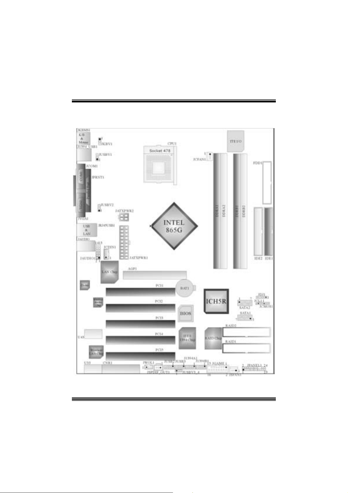
Layout of P4TSG Pro
NOTE: ●represents the first pin.
1
Page 4
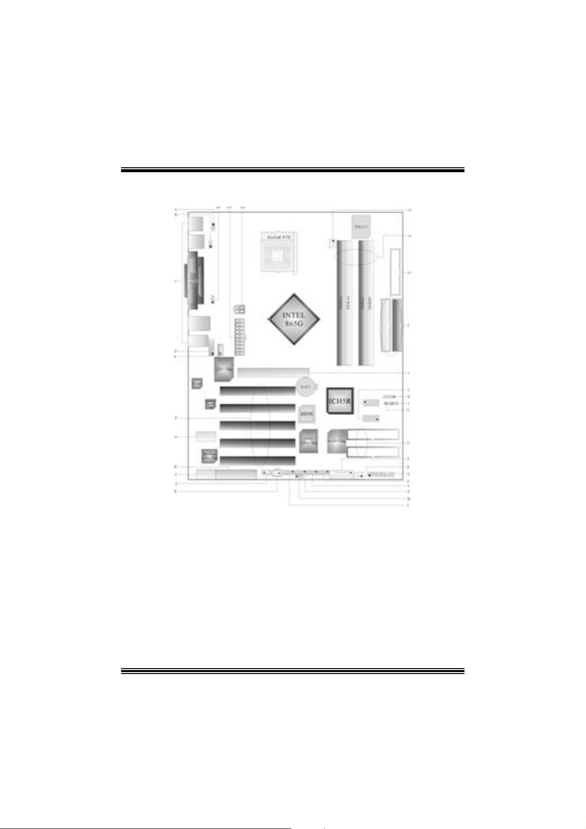
Co mponent Index
A. JKBV1: 5V/ 5VSB Sel ec tion for KB/MS Q. JPA NEL1: Front Panel Connector
B. JUSBV 1: 5V/ 5VS B Sel ection for JU SB1 R. JSFAN1: System F an Header
C. Back Panel Connectors S. J GAME 1: Game Header
D. JAUDIO 1: Front Audio Header T. RAID1-2: Ra id Connectors
E. JCDIN1 : CD-ROM Audio-In Header U. JCL1: Case Op en Connector
F. PCI1-5: Peripheral Component
Interconnect Slot s
G. U43: Wire less Audio Connector W. JDJ1 : Au dio DJ Connector
H. CNR1: Communication Network Riser
Slot
I. U33: Wi reless LAN Connector Y. AGP1: Accelerated Graphic Port Slot
J. JW OL1: W ake On LAN H eader Z. IDE1-2: Hard Disk Connectors
K. JSPDIF_OUT1: Digita l Audio Connector A1. FDD1 : Flopp y Disk Connector
L. JUSB2: F ront USB Header A2. DDRA1-2/DDRB1-2: DDR DIMM Modules
M. J USBV3_4 : 5V/ 5VSB Selecti on for USB A3. JCFA N1: CP U Fan Connector
N. JUSB3: Front US B Head er A4. JATXPW R2: ATX Power Connector
O. J139 4A1: Front 1394 Header A5. JATXPW R1: ATX Power Connector
P. J1394B1: Front 1394 Header A6. JUSBV 2: 5V/5V SB Selection for USB
V. JCMOS1: Clear CMOS Jumper
X. SATA1-2: Serial A TA Connectors
2
Page 5

English
P4TSG Pro Feat u r es
A. Har dware
CPU
Pr ov ide s S o cke t-478 .
Supports the Intel Pentiu m 4 proce ssor up to 3 .06GHz.
F ront Side Bus at 400/533/800MHz.
Su pports Hyper-Threading.
Support s Nort hwood and Prescott CPU. (W illamet t e not suppor ted)
Chipset
North Bridge: Intel 865G.
South Bridge: Int el ICH5R.
Main Me m o ry
Supports one or two 64-bit wide DDR data channels with 1 or 2 DIMMs
per-channel.
Av ailable bandwidt h up t o 3.2GB/s (DDR400) for single-channel mode and 6.4GB/s
(DDR 400) in dual channel mode.
Supports 128-Mb, 256-Mb, 512-Mb and 1-Gb DDR t ec hnologies .
Supports o nly x8, x16, DDR d evice s.( Doe s no t support r egis tered DIMMs or
double s ided X 16 DI MMs)
Supports four bank devices.
Maxi mu m me mo ry s i ze is 4GB.
Super I/O
Chip: ITE IT 8712.
Low Pin C ount Int erface.
Prov ides the most commonly used legacy Super I/O f unctionality .
Env iro nm ent C ont rol i niti atives ,
- H/W Monitor
- Fan Speed Controller
- I TE's "Smart Guardian" f unction
Slots
F ive 32-bit PCI bus mas t er s lots.
On e CN R slo t .
One AGP 4X/8X slot.
One W ireless LAN slot.
On Board IDE
Supports four IDE di s k dri ves.
Supports PIO Mode 5, Bride Mode and U lt ra DMA 33/66/100 Bus Mast er Mode.
3
Page 6

Supports 2 Serial ATA (SATA) ports.
- C om pliant wit h SATA 1.0 specif ic ation
- Data transfer rates up to 1.5 GB/s
IEEE 1394 Chi p
C hip: VIA VT6307.
Support 2 ports with transfer up to 400Mb/s.
Wireless L AN – Air Link
Chip: R TL8180L.
Full complianc e wit h IEEE802. 11 and I EEE802.11b spec if ications.
Support s Adv anc ed Configurat ion Power m anagement Interfac e.(AC PI ) and PCI
power management system for modern operating systems.
Support s rem ot e wake-up in both ACPI and APM env ironments.
Keeps network m aint enanc e costs low and eliminates us age barriers.
Uses one RF c ard for Wireless LAN.
LAN
Chip: RTL8 100B.
Supports 10 Mb/s and 100 Mb/ auto-negot iat ion
Hal f/Full du plex cap ability.
Supports ACPI power m anagement
On Bo ard AC’97 Sound Cod ec
Chip: C MI9739A/ 9760.
Compliant with AC ’97 s pec ificat ion.
AC 97 2. 2 interf ac e.
Support s 6 c hannels.
On Board Periphera ls
a. R e ar si de
1 s erial port .
1 parallel port. (SPP/EPP/ECP m ode)
1 VGA port.
Audio ports in v ert ical posit ion.
1 R J -45 LAN jack.
Support s PS/ 2 mous e and PS/ 2 keyboard.
4 USB2.0 por t s.
1 1394 port.
b. F ront Si d e
1 floppy port supports 2 F DDs with 360K, 720K, 1.2M, 1.44M and 2. 88Mby tes.
4 USB2.0 port s.
1 front audio.
Dimensions
Mic ro ATX Form Fac t or: 30.5 X 24.4c m. (W X L)
TM
4
Page 7
B. BIOS & S oftware
BIOS
Award legal BI OS.
Support s APM1.2.
Support s AC PI.
S upports USB Func tion.
Software
Supports Warpspeeder™, 9t h Touch™, FLASHER™, Watc hdog™, StudioF un! ™.
Offers the highest performance for Windows 98 SE, Windows 2000, W indows Me,
Windows XP, SC O UNIX, linux , etc.
Package contents
HDD Cable X 2
FDD Cable X1
User’s Manual X1
Fully Setup Driver CD X1
St udioF un! Application CD X 1
USB 2.0 Cable X1 (optional)
S/ PD IF Cable X 1 (optional)
Rear I/ O Panel for Mic ro ATX C as e X1 (opt ional)
Serial ATA C able X1
Se rial AT A Po w er Sw it c h C able X1
IEEE 1394 C able X1 (optional)
RF Module R is er Card
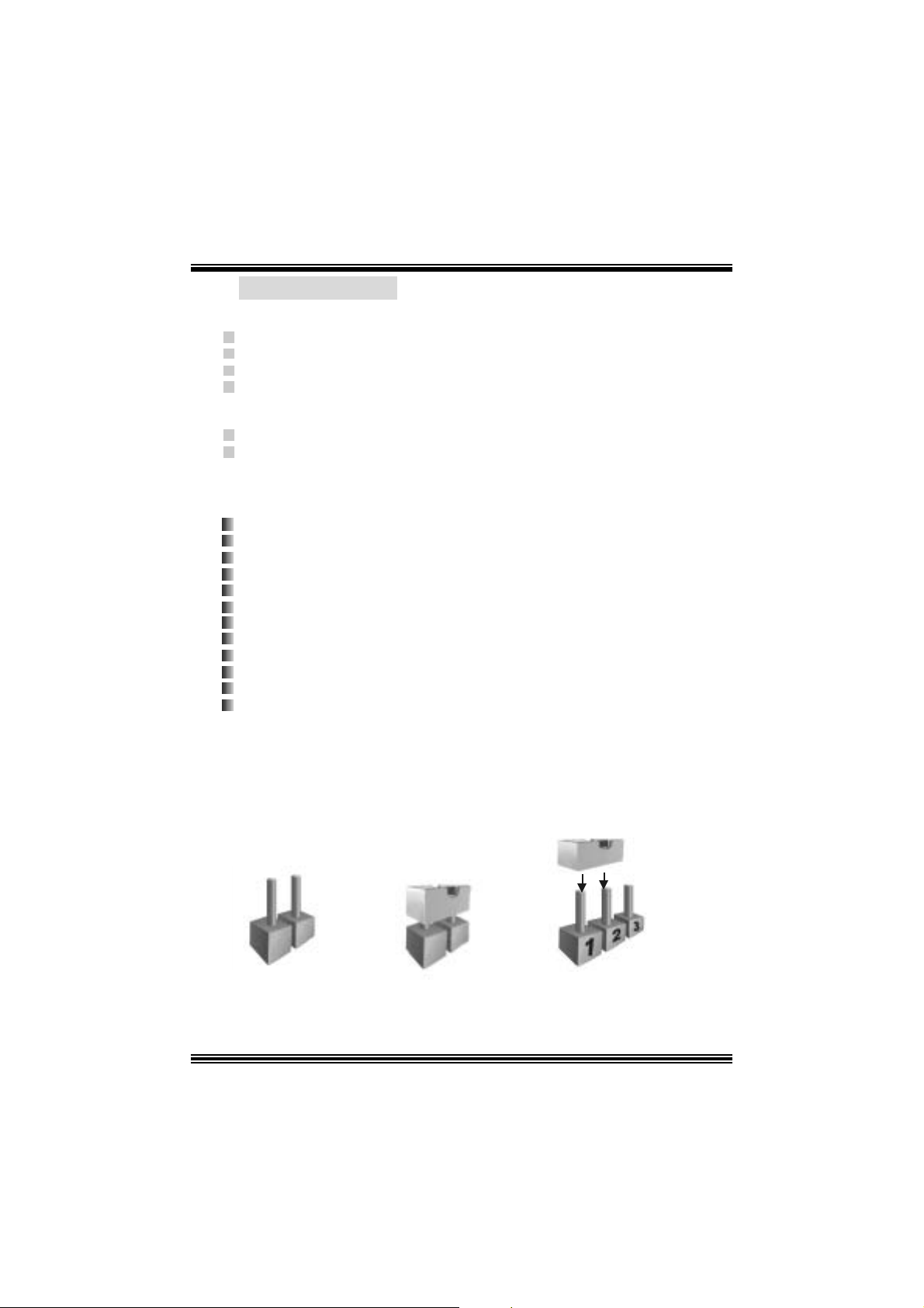
Ho w to se t up J um per
The illustration s hows to how set up jumper. When the J umper cap is placed on pins, the
jumper is “close”. If no jumper cap is placed on the pins, the jumper is ”open”. The
illust rat ion shows a 3-pin jum per whose pin1and 2 are “close” when jumper c ap is placed
on thes e 2 pins .
Jumper open Jum per close Pin1-2 close
5
Page 8
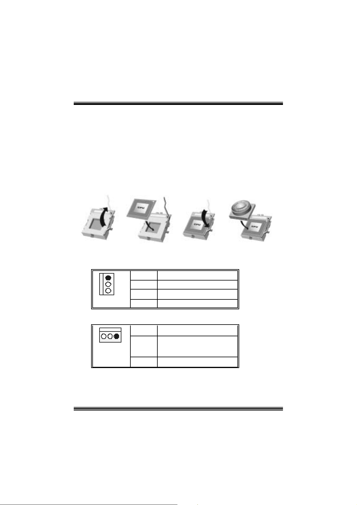
CPU Installation
Step1: Pull the lever sideway s away from the socket and then raise the lev er up to a
90 -degree angl e.
Step2: Look for the whit e dot /cut edge. The whit e dot/ cut edge should point wards the lever
piv ot. The C P U will fit only in t he co rrec t orient ation.
Step3: Hold the CPU down fir mly, an d then cl ose the lever to complete the installation.
Step4: Put the CPU Fan on the C PU and buck le it. Connect the C PU fan power cable to
the JCFAN1. This completes the installation.
Ste p 1 Step2 Step3 Step4
CPU Fan Headers: JCFAN1
1
JCFAN1
Pin Assignment
1
2
3
Ground
+12V
FAN RPM Sense
S ystem Fan Headers: JSFAN1
Pin Assignment
1
JSFAN1
1
2
3
Ground
+12V
FAN RPM Sense
6
Page 9

DDR DI MM Module s: DDRA1- 2, DDRB1-2
Support s up to four DD R DI MMs(two DI MMs per channel), single-s ided and/ or
double-sided.
F or Dual Channel Operat ion, DI MMs must be populated in identical pairs. It
has to be t he com bination of DDR A1+DDR B1 (Blue DIMMs) or DDRA2+DD RB2
(white DIMMs).
Dual Channel Guidelines
Matc hed DI MM configurat ion in eac h channel
― Same Density (128MB, 256MB, 512MB, 1GB, et c.)
― Same DR AM technology (128M-bit, 256M-bit, or 512M-bit)
― Same DR AM bus width (x8 or x 16)
― Both either s ingle-s ided or dual-sided
Matc hed in both Channel A and Channel B mem ory channels
― Populat e sym met rical mem ory slots
Opt im al platform performance with Dual C hannel, D DR400, m atched DIMMs
― Fully loaded c onfigurations can be single or double sided D I MMs
― Lightly loaded con figura tions need to be double sided DIMMs
When not using DDR400, best performance obtained with
― Symmet rical DIMM populat ion and matched double-sided DIMMs
― Lightly loaded con figura tion
7
Page 10
Dual Channel Configura tion Table
Dual Channel Conf iguration Table
•
DIMM Slot DDRA1 DDRA2 DDRB1 DDRB2 Sy stem
Density
Lightly Loaded
Config
Lightly Loaded
Config
Fully Loaded
Config
DRAM Acces s Time: 2.5V Unbuffered/ no regis tered (without ECC) DD R SDRAM
DRAM Ty pe: 128MB/ 256MB/ 512MB/ 1GB DI MM Module (184 pin)
128MB -1GB
128MB --
128MB -1GB
PC2100/ PC 2700/ PC 3200 Type required.
128MB --
1GB
128MB --
1GB
128MB --
1GB
128MB -1GB
256MB --
1GB
128MB --
1GB
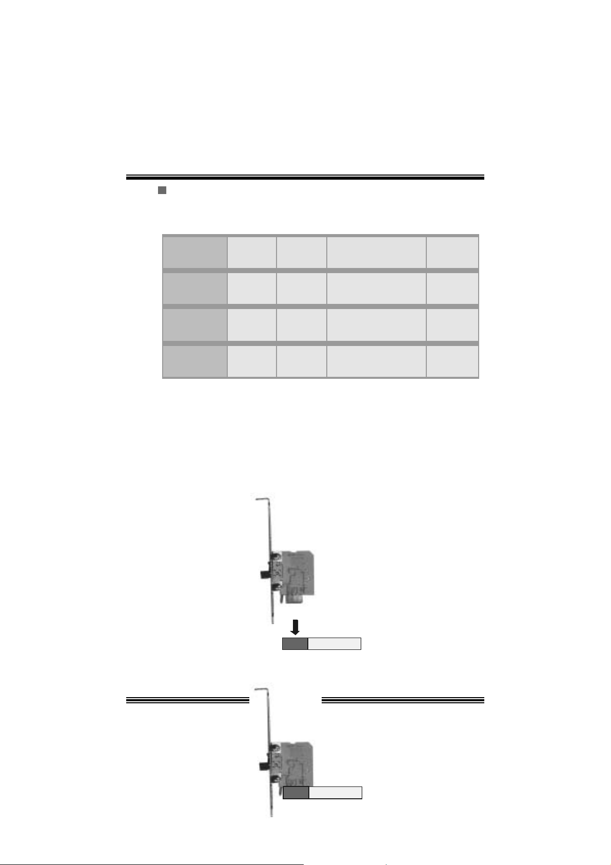
Installing Wireless LAN Card
1. Align the wireless LAN on the slot so that the wireless LAN c ard m atches in
the s lot. Be sure to f ace the wireless LAN c ard with its component s t owards
the inner part of the m otherboard as it s hows on the following picture.
2. Insert the wireless LAN card vertically and firmly into the s lot so the wireless
card is properly seated.
2GB
256MB --
2GB
512MB --
4GB
8
Page 11
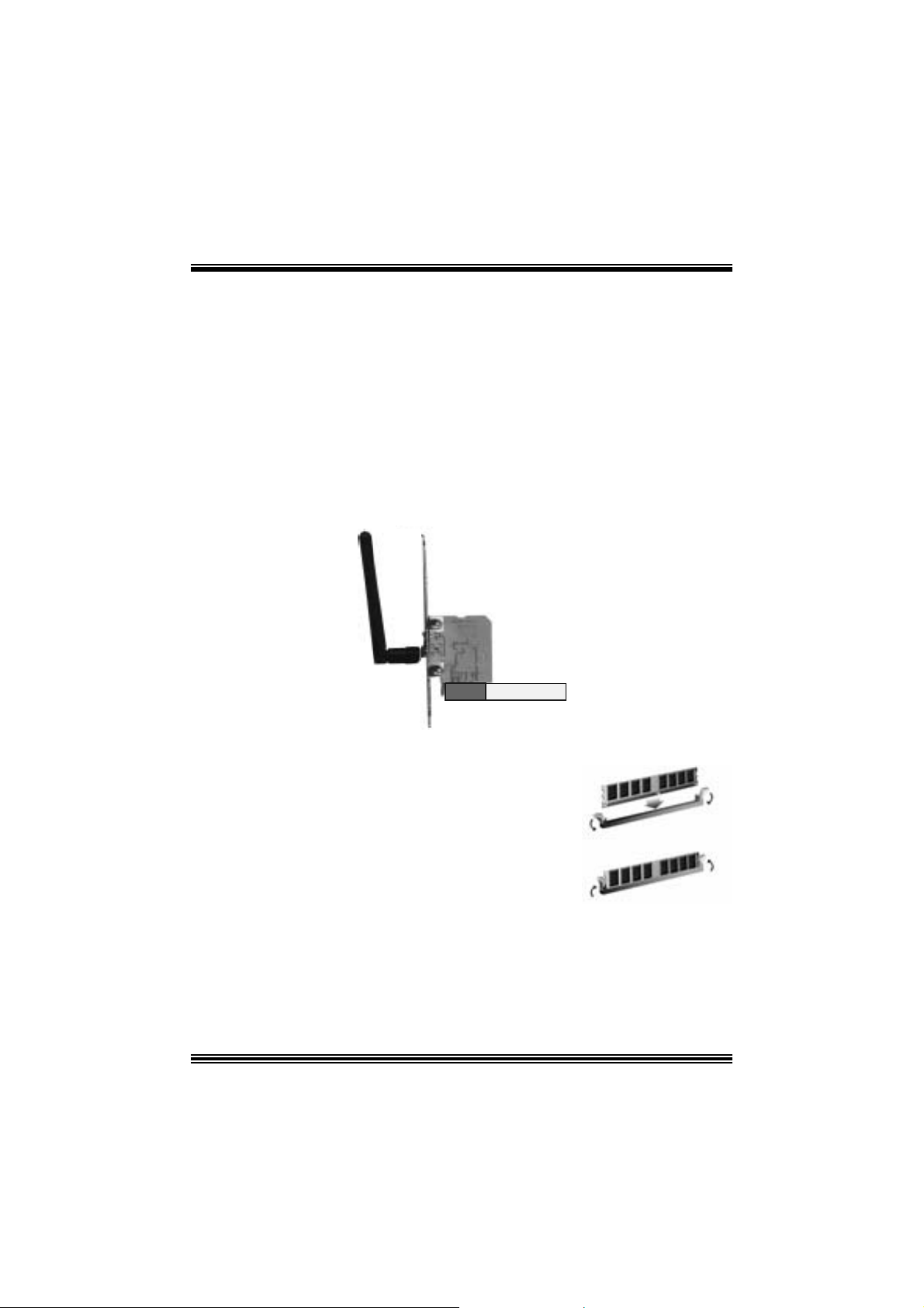
3. Screw the brackets.
4. Ins ert the wireless LAN antenna by turning it clockwis e.
Installing DDR Module
1. Unloc k a DIMM slot by pressing the retaining clips
o ut wa rd. Ali gn a D I MM on t h e sl ot s uc h t hat t he
notc h on the DIMM matches the break on the slot.
2. Ins ert the D IMM vertically and f irm ly into the s lot
until the retaining chip snap back in place and the
DIMM i s properly seated.
9
Page 12

Jumpers, Headers, Connectors & Slots
Floppy Disk Conne ctor: FDD1
The mot herboard provides a standard f loppy disk connector that supports 360K,
720K, 1.2M, 1.44M and 2.88M floppy disk types. This connector supports the
prov ided f loppy drive ribbon cables .
Hard Disk Connectors: IDE1/ IDE2
The motherboard has a 32-bit Enhanced PCI IDE Controller that provides PIO
Mode 0~5, Bus Mast er, and U ltra DMA 33/ 66/ 100 f unctionality. I t has two H DD
connectors ID E1 (primary) and IDE2 (secondary).
The ID E c onnectors can c onnect a master and a slav e driv e, so y ou can c onnect
up to four hard disk drives . The f irst hard drive s hould alway s be c onnected t o
IDE1.
Periphera l Component Int erconnect Slots: P CI1-5
This m ot herboard is equipped with 5 st andard PCI s lots. PCI stands for Peripheral
Component I nterconnec t, and it is a bus standard for expansion cards. This PCI
slot is des ignated as 32 bits.
Accelerate d Graphics Port Slot: AGP1
Your monitor will attach directly to that video card. This motherboard supports
video cards f or PC I s lots, but it is als o equipped with an Accelerated Graphics Port
(AGP). An AGP c ard will take advantage of AGP technology f or improv ed video
efficiency and perform ance, es pecially with 3D graphics.
Commun ication Netwo r k R ise r Slot: CNR1
The CNR specification is an open I ndust ry St andard Architecture, and it def ines a
ha rdw ar e scalable r iser card interfa ce, which su pports modem only.
Serial ATA Co nnector: JSATA1/ JSATA2
The mot herboard has a PCI to SATA C ontroller with 2 channels SATA int erf ace, it
satisfies the SATA 1.0 spec and can transf er data wit h 1. 5 Gbits/s speed.
10
Page 13
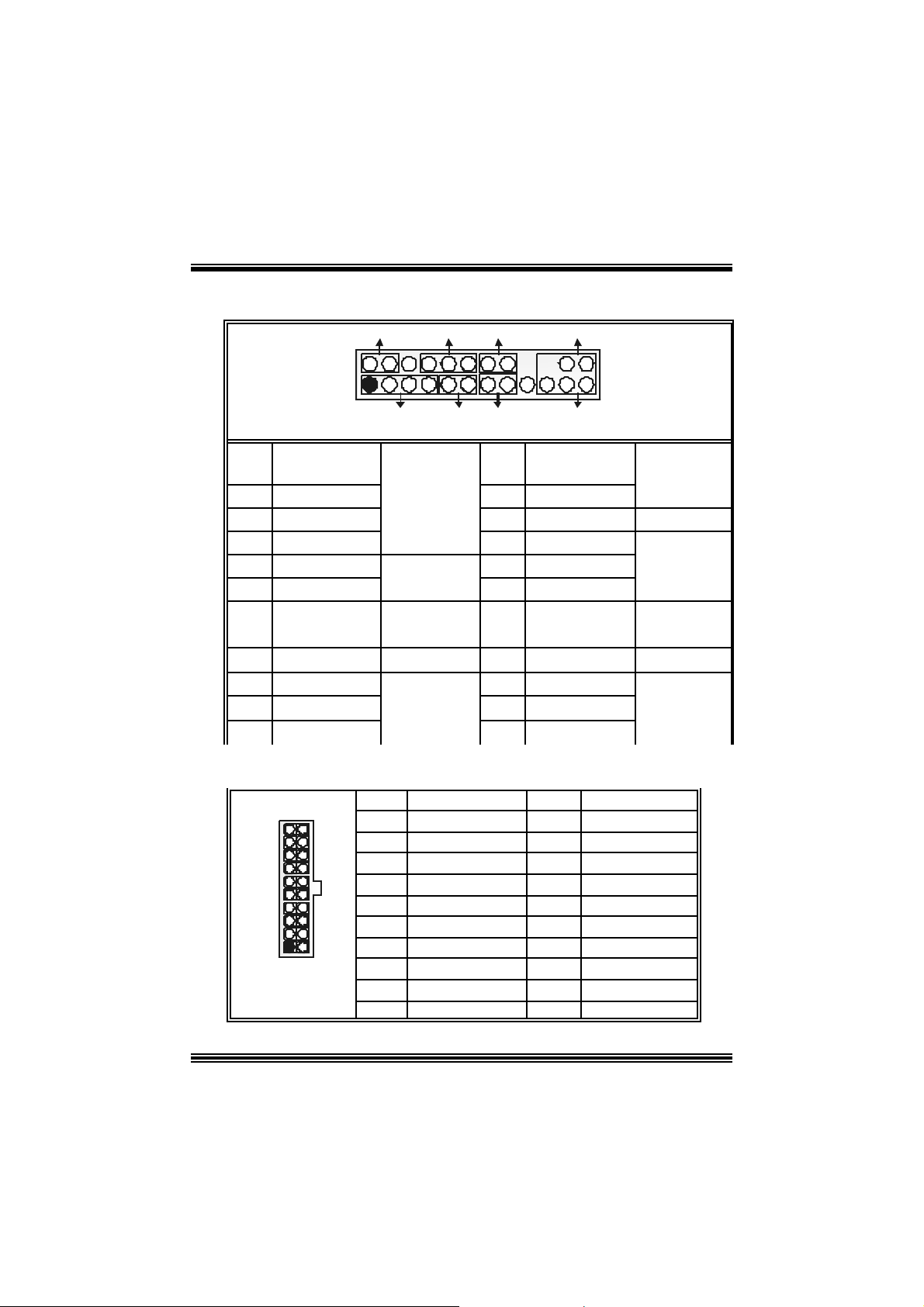
Front Pane l Conne ctor: JPANEL1
SLP
JPANEL1
Pin Assignment Function Pin Assignment Function
1 +5V 2 Sleep Control
3 NA 4 Ground
5 NA 6 NA NA
7 Speaker
9 HDD LED (+) 10 Power LED (+)
11 HDD LED (-)
13 Ground 14 Power Button
15 Reset Control
17 NA 18 KEY
19 NA 20 KEY
21 +5V 22 Ground
23 IRTX
2
1
PWR_LED
SPK
HLED
RST
Speaker
Connector
8 Power LED (+)
Hard Drive
LED 12 Power LED (-)
Reset
Button 16 Ground
IrDA
Connector
24 IRRX
IRON/OFF
IR
24
23
Sleep
Button
POWER
LED
Power-on
Button
IrDA
Connector
Power Conn ectors: JATXPWER1/ JATXPWR2
10
1
JATXPWR1
20
11
PIN Assignment PIN Assignment
1
2
3
4
5
6
7 Ground 17 Ground
8
9
10
+3.3V
+3.3V
Ground
+5 V
Ground
+5 V
PW_OK
+5V_SB
+1 2V
11
11
12
13
14
15
16
18
19
20
+3. 3V
-12V
Ground
PS_ON
Ground
Ground
-5V
+5V
+5V
Page 14
PIN Assignment PIN Assignment
1
2
+12V
+12V
3
4
Ground
Ground
JATXPWR2
1
3
2
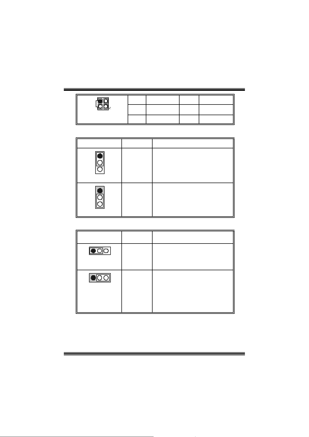
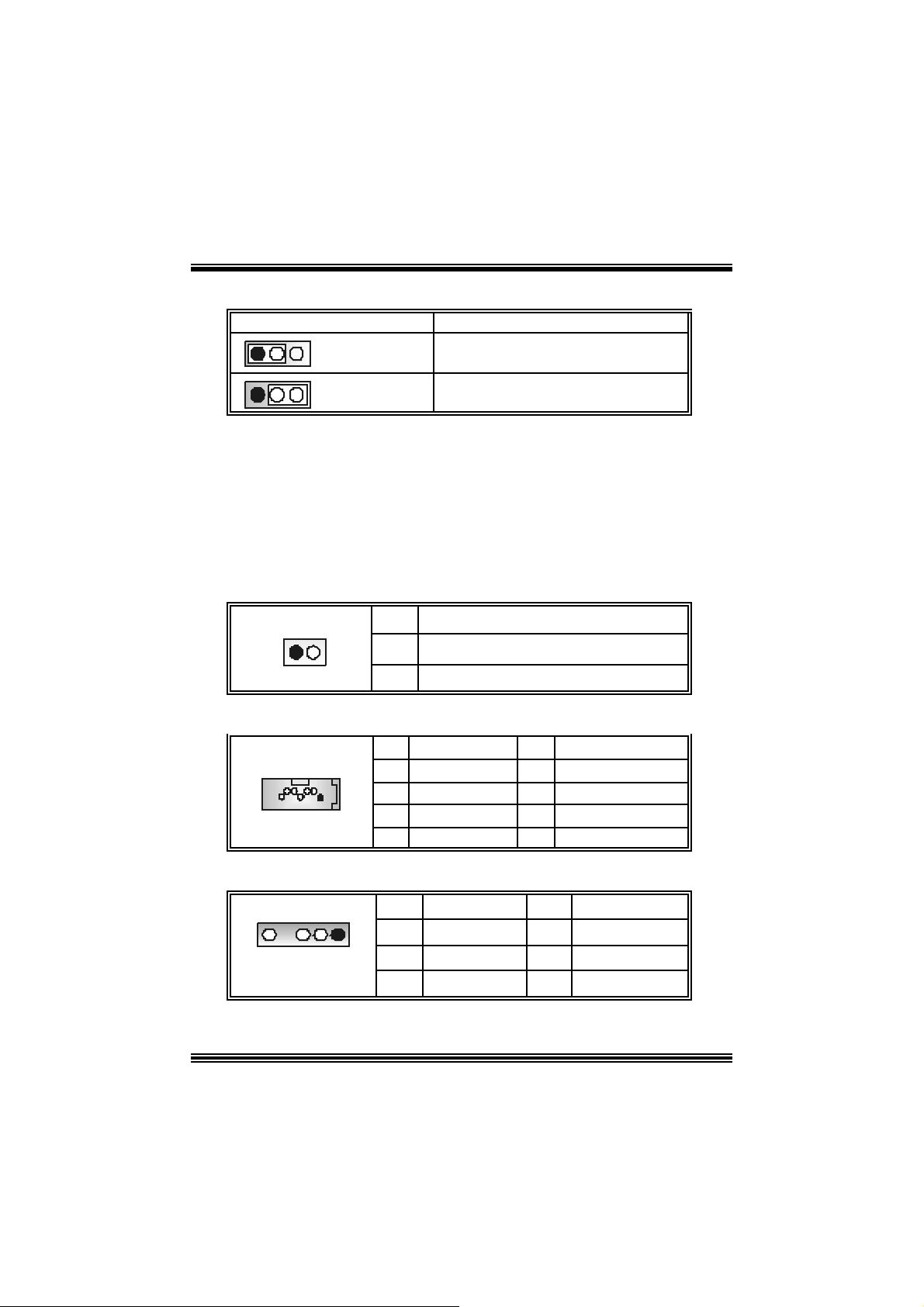
5V / 5VSB Selection for KB: JKBV1
JKBV1 Assignment Description
5V for ke yboa rd and mouse
5 V standby for keyboard and mouse to
po w er on your system
Pin 1-2 c los e
Pin 2-3 c los e
1
3
1
3
+5 V
+5V_SB
5V/ 5VSB Selection for USB: JUSBV1/ JUSBV2/J USBV3_ 4
JUSBV1/JUSBV2/
JUSBV3_4
1 3
Pin 1-2 c los e
Assignment Description
+5 V
5V JUSBV1 for JUSB1 port
5V JUSBV2 for J RJ45US B1 por t
5V JU SBV3_4 for JUSB2/3 ports
1 3
Pin 2-3 c los e
+5V_SB
JU SBV1 5V standby to power on
JU SBV2 5V standby to power on
JU SBV3_4 5V standby to power on
12
JU SB1 port
JRJ45U SBV1 port
JU SB2/3 ports
Page 15
Clear CMOS Jumper: JCMOS1
1 3
1 3
JCMOS1 Assignment
Pin 1-2 C los e
Pin 2-3 C los e
Norm al Operation (def ault)
Clear CMOS Data
※ Clear CMOS Procedures:
1. R emov e AC power line.
2. Set the jumper to “Pin 1-2 C lose”.
3. Wa it for fi ve seconds.
4. Set the jumper to “Pin 2-3 C lose”.
5. Power on t he AC .
6. R eset your des ired password or clear t he C MOS dat a.
Ca se Op e n Connec to r: JCL1
Assign ment
Case Open Signal
Ground
1
JCL1
Pin
2
1
2
Serial ATA Co nnector: JSATA1/ JSATA2
1234567
JSA TA1/ JSATA2
Pin Assignment Pin Assignment
1
3
5
7 Ground
Ground
TXRX-
2
4
6
AUDIO DJ Connector: JDJ1
JDJ1
Pin Assignment Pin Assignment
SMBDATA
1
15
3
5
INT_B
ATX_PWROK
2
4
TX+
Ground
RX+
SMBCLK
KEY
13
Page 16
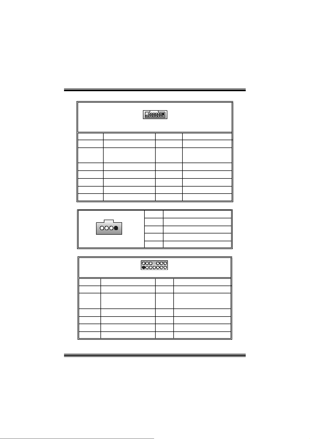
Game Header: JGAME1
JGAME1
1
216
2
4
6
8
10
12
14
16
GPSB1
R_GPX1
Ground
Ground
R_GPY 1
GPSA2
15
Pin Assign m ent Pin Assignment
1
3
5
7
9
11
13
15
+5V
GPSB1
R_GPX2
MI D I-OUT
R_GPY2
GPSB2
MIDI-IN
NA
CD-ROM Audio-In Heade r: JCDIN1
1
JCDIN1
Pin Assignment
1
2
3
4
Left Channel Inp ut
Ground
Ground
Right Channel In put
Front Panel Audio Header: JAUDIO1
+5V
+5V
2
1
JAUDIO1
Pin Assignment Pin Assig nment
1
3
5
7
9
11
13
Mic In
Mic Po we r
RT Line Out
Reserved
LFT Line Out
RT Line I n
LET Line In
14
14
13
2
4
6
8
10
12
14
Ground
Audio Power
RT Line Out
Key
LFT Line Out
RT Line In
LET Line I n
Page 17
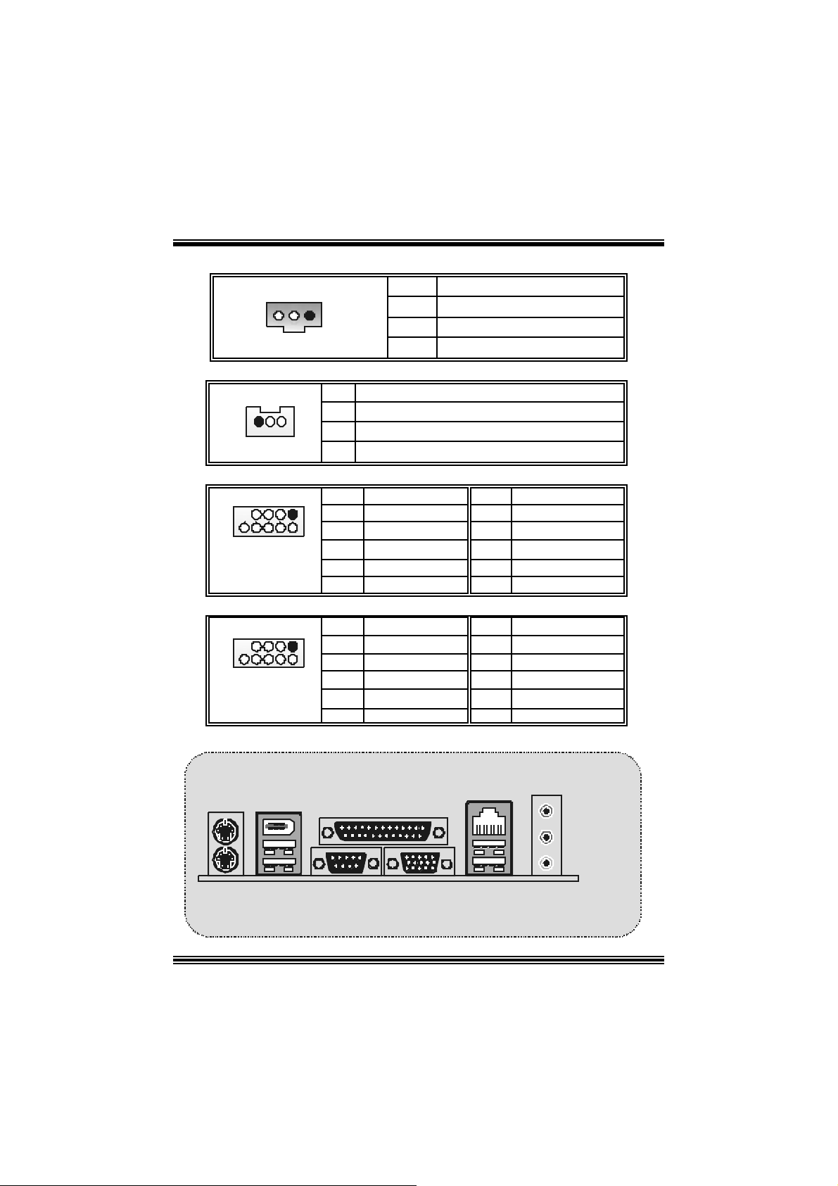
Digital Audio Connector: JSPDIF_OUT1
1
JSPDI F_OUT1
Pin Assignment
1
2
3
Wake On LAN He ader: JWOL1
+5V
SPDIF_OUT
Ground
1
JWO L1
Pin Assignment
1 +5V_SB
2
3 Wake up
Front USB Header: JUSB2/3
Pin Assignment Pin Assignment
1
1
3
2
5
7
9
+5V(fused)
USBP
USBP
Ground
KEY
9
10
JUSB2/3
Front 1394 Header: J1394A1/ J1394B1
Pin Assignment Pin Assignment
1
1
3
2
5
7
9
A+
Ground
B+
+12V
KEY
9
10
J1394A1/ B 1
B ack Panel Connectors
JKBMS 1
PS/2
Mou se
1394
JPRNT1
Paral lel
Ground
2
4
6
8
10
2
4
6
8
10
JRJ45USB1
LAN
+5V(fused)
USBP
USBP
Ground
NC
A-
Ground
B-
+12V
Ground
Line In
Speaker Out
PS/2
K eyboard
J1394_USB1
USB
COM1
JCOM1
VGA1 USB
JVGA1
15
Mic In
JAUDIO
Page 18
StudioFun!
Introduction
StudioF un! is a media-player based on optimized GNU/ Linux distribution. It play s D VD,
VCD , MP3, Audio CD and various other k nown file f ormats. You can tak e s naps hots of
video and customize the saved images as screens avers. Y ou can also store the images
on USB mass storage dev ic es like flash disks and USB floppy disks.
Hardware Requirements
The supported hardware list of StudioFun! grows up every day. So please check the
hwreq.txt located in the root of StudioFun! Installation CD to get the most updated
information.
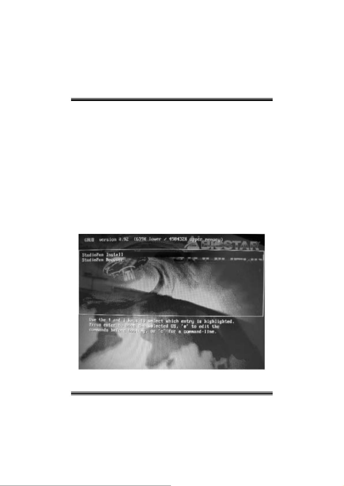
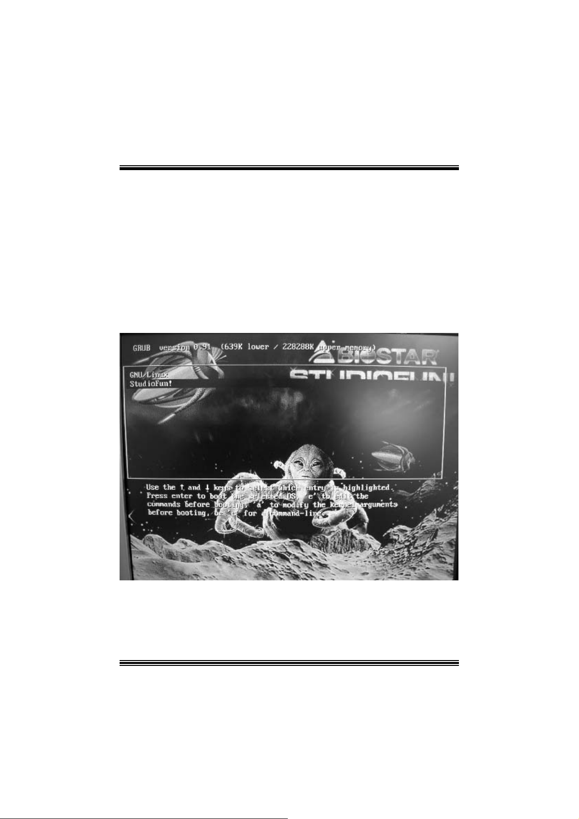
Ins tallatio n Proce dure
Ins ert the StudioFun! Installation CD in a CD/DVD ROM drive and let the system boot
through the CD. The dis k will boot and bring up the grub boot loader installation menu.
Two opt ions are specif ied.
16
Page 19

Installation
This option will do the basic installation of the distribution. The installation works on
pre-inst alled windows or GNU / Linux dist ribution.
On select ing the ’installat ion’ option the inst aller boots and display s a dialog box indicat ing
the s pace required and waits f or a confirmation. Selecting Ok will c ontinue the inst allat ion
while select ing Canc el will t erm inate t he installation and reboot the mac hine.
If Windows or GNU/Linux is the only OS installed on the hard disk wit h no f ree space, it
will resize the partit ion, eit her NTFS or FAT32 or ex t 2, and install StudioFun!. I n c as e the
hard dis k has a 128MB of free s p ace av ailable, t he installatio n will us e the f ree spac e.
Aft er installing the base system y ou will be prompt ed to select the res olution f rom the
following choice s
1. 1024x768 (rec om m ended)
2. 800x 600
3. 640x 480
Select the desired res olut ion. The default is 1024x768 for high-end graphic s.
Nex t y ou will be prompted t o c hoose t he DVD area/region s elec tion code. Choose t his
bas ed on the ty p e of D VDs y ou will b e playing.
The installation procedure will then probe for the type of mouse installed. The distribution
currently supports PS/2, USB and Serial mice. In case of serial m ouse you will hav e to
mov e the mouse when prompt ed. The ot her two are probed and installed automatic ally.
The installation procedure will now finish, the CD is eje c ted and a dialog box prompting to
reboot t he m achine is dis play ed. Pres s OK butt on and enjoy StudioFun!.
3.1.1 Error Messages
1. Media c orrupted!! Pleas e check the media! The CD -RO M is corrupt ed.
2. Extract ion of base sy s tem failed!! Pleas e try again later!! The C D -ROM is corrupted.
3. Unsupported hardware found, Aborting... If you try to install StudioFun! on an
unsupported and undocumented hardware the abov e error m ess age is popped.
4. N o device found! This error message is given if t here is no hard disk in the sy stem.
17
Page 20
Recovery
In c ase of a MBR c orruption, this option should be us ed. It will aut omatically probe the
hard disk m aster boot record and f ind out the inst alled operat ing system(s ). On succ ess it
will re-inst all the boot loader with correct options in the MBR. Any c ustom boot loader
option specified from other GNU/Linux installations will get over written by the newly
probed one.
B o oting to S t udioF un!
After Installation is ov er, rem ove the CD f rom the CD-ROM and restart the machine. After
the machine reboots, you will get the GRUB boot loader menu screen. Select the
StudioF un opt ion to boot to the St udioFun! partition.
18
Page 21
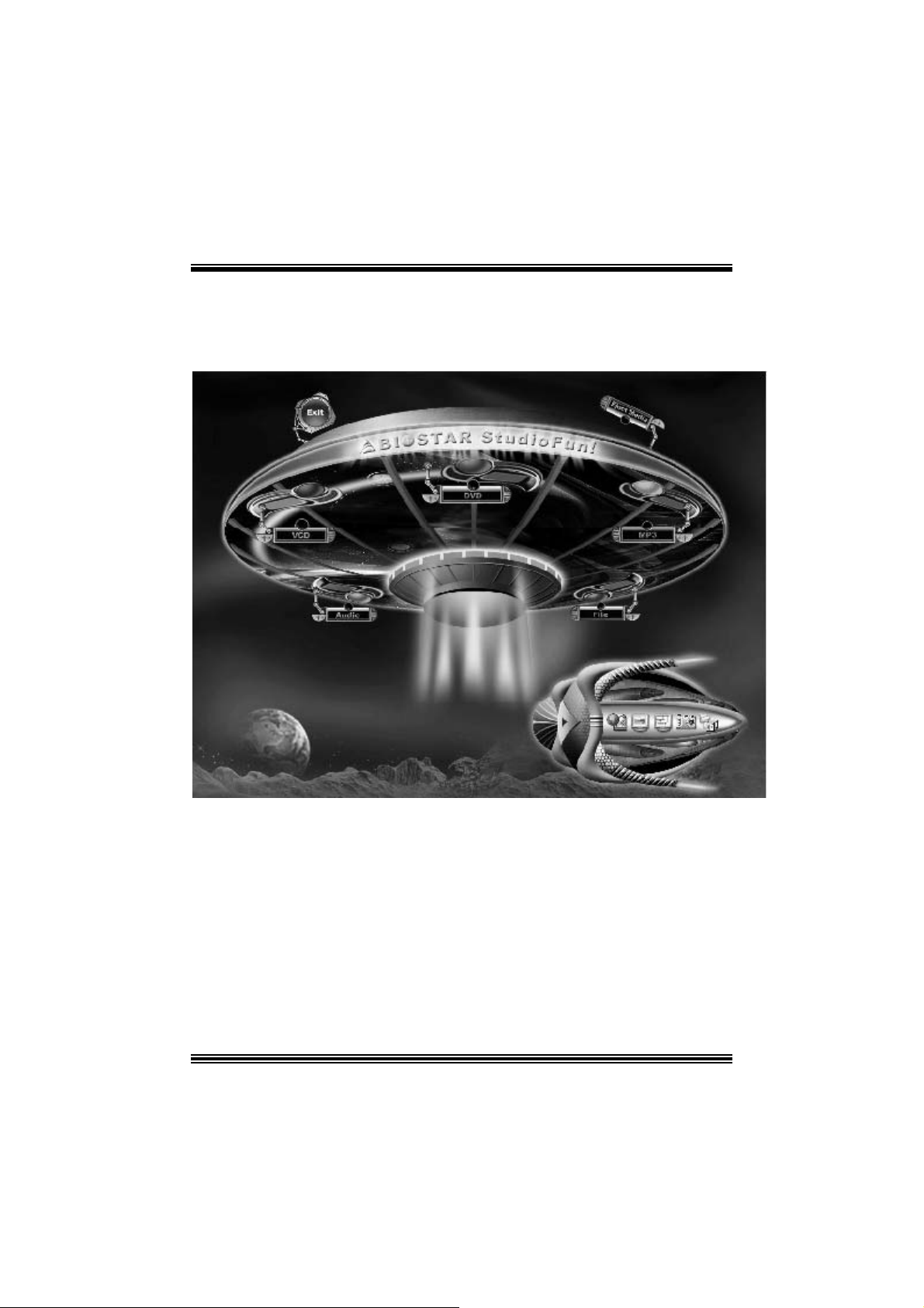
After comple te bo ot up, you get to th e main Des ktop screen. Th e followi ng section is
a com plete descript ion of the Desktop applicat ion.
Desktop
This is t he m ain shell of t he StudioFun s of t ware. It basic ally com prises of two cat egories ,
one is the main "media control" part and t he other is the "control panel".
Media control
The media c ontrol part of t he D eskt op has the following cont rols:
1. VCD
This c ontrol will glo w whenev e r a VCD is d etected in a DVD/CD-R OM drive. The VCD will
be auto-play ed only when it is put in to the drive when the Desktop (StudioF un! shell) is up
and running, otherwise, the control will simply glow to inform the user about a VCD
19
Page 22

present in t he DVD/CD-ROM driv e.
2. DVD
This control will glow whenever a DVD is detected in a DVD drive. The DVD will be
auto-played only when it is put in to the driv e when the D esk top (St udioFun! shell) is up
and running, otherwise, the control will simply glow to inform the user about a DVD
present in t he DVD/CD-ROM.
3. MP3
This c ontrol will glo w whenev e r a MP3 is detected in a DVD/CD-R OM drive. The MP3 will
be auto-play ed only when it is put in to the drive when the Desktop (StudioF un! shell) is up
and running, otherwise, the control will simply glow to inform the user about a MP3
present in t he DVD/CD-ROM driv e.
4. AU DIO
This control will glow whenev er a AUDI O is detec ted in a D VD/CD -ROM driv e. The AUDI O
will be auto-play ed only when it is put in t o t he driv e w hen the Desktop (StudioFun! shell)
is up and running, otherwise, the control will simpl y glo w to inf orm the user about a AUDI O
present in t he DVD/CD-ROM driv e.
5. FILE
This co ntrol will glow whenever a File C D (CDs with other media type files) is det ect ed in a
DVD/CD-ROM drive. The File CD will be auto-play ed only when it is put in to the driv e
when the D esktop (StudioFun! shell) is up and running, otherwise, the control will simply
glow to inform the user about a F ile CD present in t he D VD/CD -R OM driv e.
6. EJECT MEDIA
This cont rol when c lick ed will ejec t any MP3 or File CDs f rom any of the DVD/C DR OM
driv es. In case there were no MP3 or File CDs it will eject the def ault medium, (i.e.), the
CD -ROM driv e in c ase if the user has both D VD/ CD-ROM driv e or else it will eject the
default DVD /CD-ROM drive .
7. EXIT
This is the "Power on/ off" control of the D esktop (StudioFun! shell).
Co nt ro l Pa nel
Cont rol panel part has five icons, which are shortcuts t o other applic at ions pres ent in t he
StudioFun sof tware. Tool tips are provided on t he icons when the m ous e is rolled over
them.
20
Page 23

1. Select Region
Click ing t his icon will inv oke t he application f or s ele ct ion D VD regio n sett ings. Refer to
sec t ion 5. 2 Select DVD Region application for more details.
2. Screensaver
Clicking this icon will invoke the screensav er application. Refer to section 5.3
Screensaver for more details.
3. Display Settings
Clicking this ic on will inv oke t he applicat ion for c hanging the screen resolutions. Ref er t o
se cti on 5.4, D i sp l a y Se ttin g s f or more det ails.
4. File Manager
Clicking thi s icon will invoke the file manager. Re fer to section 5 .6 File manager fo r m o r e
details .
Wh en u ser h as a DVD and a CD -ROM Drive:
If user has bot h DVD and a CD -R OM drive, DVD driv e will be giv en t he pref erence when
both the drives hold valid media in them , i.e., if the CD -ROM driv e has a media and a DVD
drive also has a media, and the StudioFun! is start ed, then the media ins ide t he DVD driv e
will be play ed.
If in c ase the media in CD-R OM takes a longer tim e t o get recognized than the media
insid e t he D VD drive, th e media in the CD -R OM will be play e d, onc e if it is reco gnized.
Other general user scenarios
When a user clicks o n a ny of th e m edi a -c o n t rols when it is not glowing, exc ept eject m edia
and exit, the media-player will just com e up and wait f or user input .
NO DUPLIC ATE INSTANCE OF ANY APPLIC ATION WILL BE ALLOWED TO
RUN.
21
Page 24

S oftware Details
XIN E
XI N E is a m ultimedia player. I t plays bac k Audio CD, DVD, and VCD. It also decodes
mult imedia files like AVI, MOV, WMV, and MP3 from loc al dis k drives . I t interprets many of
the m ost common multimedia form ats available - and som e of the unc omm on formats,
too.
• Features of Xi ne
a. Skinnable GUI
b. N avigation controls (seeking, pause, fast, slow, next
chapter, etc)
c. On Screen Display (OSD) feat ures
d. DVD and external subt itles
e. DVD/VCD menus (requires external plugin)
f. A udio and subtitle channel selection
g. Cl osed Caption su ppo r t
h. Brightness, contrast, audio volume, hue, saturat ion
adjusting requires hardw are/driver support)
i. Playlists
j. Image snapshot
k. A udio resampling
l. Soft ware de-interlacing algorithms
m. Configuration dialog
n. Aspect ratio ch anging
o. Fullscreen display
• Supported File fo rmat s
a. Vide o CD
b. MPEG program streams (.mpg, .mpeg)
c. ogg (. ogg) avi (.avi)
d. asf (.asf, .w mv)
e. QuickT ime (.mov )
22
Page 25

f. MPEG-Video (.mpv, .m2v)
g. MPEG-A udio (.mp2, .mp3)
h. WAV (.w av) Video Codecs
i. MPEG 1/2
j. MPEG 4 (aka OpenDivX)
k. MS MP EG 4
a. C hapter 5: Software Details 10
l. Windows Media Video 7
m. Motion JPEG
• Remote Cont rol sup p ort.
a. Infrared int erface
b. U ser-friendly
• Usage of S tudioFun! with CelomaChrome skin
a. Select VCD but ton to play a VCD disc
b. Select DVD button to play a DVD disc
c. Select CDDA button to play a Audio cd
d. Sel ect next chapter or M RL (>>|) button t o play next track
in Audio CD, VCD and MP3 songs and to play next
chapter in DVD
e. Select p revious chapter or M RL (|<<) button to play
previous t rack in Audio CD, VCD and MP3 songs and to
play previous chapter in DVD
f. Sel ect slow mot ion (<<) butt on to play t he video / audio in
slow motion (Select play b utton after reaching t he required
position)
g. Select fast motion (> >) button to play the video / audio in
fast mot ion ( Select play button after reaching the required
position)
h. Select subs + / - button to select the appropriate su btitle
(Usable while pla ying
i. Select audio + / - button to select the appropriate audio
track (For example when
j. The DVD contains one audio track in English and the
other wit h some ot her language,
k. Usab le while playing DVD’s)
23
Page 26

l. j. Select hide button to hide the control panel of the player
m. k. Select menu button to use menu’s while p lay ing DVD
n. l. Sele c t con trol button to adjust brightness / color
o. Select setup button to modify the settings of th e player
p. Select f.scr button to show the video output of the play er in
q. Sel ect snap button to take a snapshot of the currently
r. Sel ect plist button to add / remove / mana ge playlist
s. Select mrl button to add new file to play
Error Messa ges
full screen mode
playing video
T he following erro r message is given if an unknown
file format is selected through Xine MRL browser
and played.
While playing mp3 files, if the user stops playing and
tries to select the DVD button, then the following
error message is shown
Select Region
Overview
Select region is a ut ility to set a DVD region. With t he help of t his applic ation us er can set
or change a DVD region. Only one region c an be set at a tim e.
About Select Region
Wit h the help of t his application y ou c an set a region for DV D. Only one region can be set
at a time. If y ou keep the mous e point er on any region, y ou can v iew t he c ount ries, which
comes u nder that region.
Ok - Click to set the selected region.
Canc el - Click to quit the application.
How to select DVD region
You can selec t only one region at a time. You can change your selec tion by clicki ng on
any ot her region.
• A snapshot of the applicat ion is shown below:
24
Page 27

Screensaver
Screensaver
The xscreens aver daem on waits until t he k eyboard and m ous e have been idle for a period,
and then runs a graphics demo chosen at random. The dem o is term inated as s oon as
there is any m ouse or key board act iv ity.
The xscreensaver-demo program is the graphical user interface to xscreensaver. It lets
you t une the v arious paramet ers us ed by the xscreensav er daemon, and browse through
the graphics dem os.
StudioF un! com es with xscreens aver when you click on the sc reensav er ic on the
applicat ion com es up. Then user c an c hoos e v arious graphics dem os like
chbg, halo,hypercube or hyperball.
Screensa ver come s with various options
• Preview Option: W hen a user selects a particular graphic s demo and clicks on preview
button the demo come s up.
• Blank After Option: The screens aver will blan k the screen aft er t he keyboard and mous e
have been idle default t im e is 1minut e and user c an change the s ett ings.
• Cycle After Option: When screensaver is running this cycle time defines the time lim it f or
each screensav er.
• Mode Screens aver com es with various modes:
1. R andom Screen Saver: W hen user choos es t his option, Screens av er cyc les t hrough
various graphic s dem os randomly
25
Page 28

2. Only one Screen Saver: W hen user chooses this opt ion, screensav er display s only one
graphics dem o.
3. Blank S creen O nly: When user choose s thi s option, screensaver only blan ks the screen
inst ead of dis playing t he graphics demo.
4. D isable Screen Saver: When user chooses this option, screens av er is disabled.
• Various G raphics Dem os
XSc reensaver comes wit h various screens aver
Chbg: This screensav er displays the images stored in StudioFun! t he time gap between
images is 5 seconds.
Hyperball
Hyperc ube
Halo
Strange
• A snapshot of the applicat ion is shown below:
Display Settings
Display Settings
Displa y setting is a progra m to change the current resolution settings of the Display.
By def ault user of St udioF un will be given a choic e to select between any of the fo llow ing
26
Page 29

three resolut ions.
• 640x480
• 800x600
• 1024x768
The current resolution of t he Display will be selected by default. It requires rest art of t he
StudioFu n to re flect the changes made.
File Manager
Overview
File manger is an u tility to cop y file s from de ferent de v ice s to hard disk and vi ce versa.
Us er can copy files f rom dev ices such as, floppy, cdrom and flashdisk to hard disk. And
also fro m hard dis k to floppy and flashdi sk.
About File manager
The hard disk files are stored in a direct ory called “/studiofun” on t he hard disk. You can
also delete files from hard disk, bu t you cannot delete file s from any de vi ce.
Select device - C ont ains t he devic e names /f loppy, /c drom and /f las hdisk. Select a
device fro m /to which you want to copy fi les .
twice to mount the device.
List Directories - Shows the list of directories of the s elected device af t er double
click in g it.
Floppy /cdrom/Flashdisk - Shows the c ontent s of the selected directory from t he “List
direc t ories“ f ield aft er double click ing it.
Hard disk - Shows the cont ents of a directory c alled “/ studiof un”.
Add (>>) - Click to copy selected files from a device to hard disk.
Add (<<) - Click to copy selected files from hard disk to a device.
Remove - C l i ck to delete fil e s from hard disk.
Exit - Click to quit the application.
P l ease do u b l e cl ic k th e d evice o p ti o n
27
Page 30

28
Page 31

WarpSpeeder
Introduction
[ W arpSpeeder™ ], a new powerf ul control utility, f eatures three us er-f riendly functions
including Ov erclock Manager, Ov ervoltage Manager, and H ardware Monit or.
With the Over clock Manage r, users can easil y adjust the frequency the y prefer or they can
get t he best CPU perf ormanc e wit h jus t one click . The Ov ervoltage Manager, on the other
hand, helps to power up CPU core voltage and Memory voltage. The cool Hardware
Monitor smartly indic ates the t emperatures, volt age and CPU fan speed as well as the
chips et inform at ion. Also, in t he About panel, you c an get det ail des c ript ions about BI OS
model and chipsets. In addition, t he frequency status of CPU, memory, AGP and PC I
along with t he C PU s peed are synchronically shown on our m ain panel.
Moreov er, to protect users' c om puter sy s tems if the s etting is not appropriat e when testing
and results in system f ail or hang, [ WarpSpeeder™ ] technology assures the system
st ability by automat ically reboot in g the c om puter and then restart t o a speed that is either
the original sys t em speed or a s uit able one.
System Requirement
OS Support : Windows 98 SE, W indows Me, Windows 2000, Windows XP
Direc t X: DirectX 8.1 or abov e. (The W indows XP operating sys tem inc ludes D irectX 8. 1. If
you us e W indows XP, y ou do not need t o inst all D irectX 8. 1. )
29
Page 32

Installation
1. Execut e the setup ex ecution f ile, and then the following dialog will pop up.
Please clic k “Nex t ” button and follow the def ault procedure to install.
2. When you see the f ollowing dialog in setup procedure, it means setup is
comple ted . If th e “Launch the War pSpeeder Tray Utility” checkbox is che cked,
the Tray Icon utility and [WarpSpeeder™] utility will be automatically and
imm ediately launched after you click “Finish” butt on.
30
Page 33

Usage
The foll o win g fi gu r es ar e ju st on l y for re f er enc e , th e s c re en pr in ted in th is u s er ma nual will
change according to your motherboard on hand.
[W arpSpeeder™] includes 1 tray icon and 5 panels:
1. Tray Icon:
Whenev er the Tray Icon utility is launched, it will dis p lay a litt le tray ic on on t he right side of
Windows Tas k bar.
31
Page 34

This utility is responsible f or conveniently invok ing [WarpSpeeder™] Utility. You can use
the m ouse by clicking t he lef t butt on in order t o inv oke [WarpSpeeder™] direct ly from the
litt le t ray icon or you can right-c lick t he lit t le t ray icon to pop up a popup menu as following
figure. The “Launch Utility” item in the popup menu has the sam e function as m ouse
left -c lick on tray icon and “Exit ” item will close Tray Ic on utility if selec t ed.
2. Main Panel
If you click the tra y icon, [ WarpSpeeder™ ] utility will be invoke d. Please refer
do the following figure; the u tility’s fi rst window you will see is Main Panel.
Main Panel contains features as follows:
a. Display the C PU Speed, CPU ex ternal c lock, Mem ory clock, AGP c lock, and PCI
cloc k inform at ion.
b. Contains About, Voltage, Overclock, and Hardware Monitor Buttons f or invoking
respective panels.
c. With a user-friendly Status Animation, it can represent 3 overclock percentage
stages:
Duck walk ing => overcloc k perc entage from 100% ~ 110 %
Duck running => overclock percentage from 110% ~ 120%
Duck burning => overclock percentage from 120% ~ abov e
32
Page 35

3. Voltage Panel
Click t he Volt age button in Main Panel, the button will be highlighted and the Voltage
Panel will slide out to up as t he f ollowing figure.
In this panel, y ou can decide to increase C PU core voltage and Mem ory voltage or not .
The def ault setting is “No”. If y ou want to get the best perf ormance of ov erc locking, we
r ec ommen d y ou c lic k th e opti on “Y es”.
33
Page 36

4. Overclock Panel
Click t he Ov erclock button in Main Panel, the butto n will be highlighted and the Ov erc lock
Panel will slide out to left as the following figure.
34
Page 37

Overclock Panel contains these features:
a. “–3MHz button”, “-1MHz but ton”, “+1MHz butt on”, and “+3MHz but ton”: provide user
the a bility t o do real-t ime ov erc lock adjustment .
Warning: Manually overcl ock i s potenti ally dangerous, especially when the
overclocking percentage is over 110 %. We strongl y recommend you verify
every speed you overclock by cli ck the Verify button. Or, you can just click
Auto overclock button and let [ WarpSpeeder™ ] automatically gets the best
result for you.
b. “R ecovery Dialog button”: Pop up t he f ollowing dialog. Let user select a rest oring
way if sy s tem need to do a f ail-safe reboot.
35
Page 38

d. “Aut o-ov ercloc k button”: User c an click this button and [ W arpS peeder™ ] will set
the best and stable perform anc e and frequency automatic ally . [ W arpSpeeder™ ]
utility will exe c ute a s e ries of testin g until syst em fail. Then sys t em will do fail-s af e
reboot by us ing Watchdog f unct ion. Aft er reboot, the [ WarpSpeeder™ ] utility will
restore to the hardware default setting or load the verified best and stable
frequency a c cording to the Reco ver y Dialog’s setting.
e. “Verif y but ton”: User can c lick this button and [ WarpSpeeder™ ] will proceed a
testing for current frequenc y. If the testing is ok, then the c urrent frequen cy will be
sav ed into system registry . If the testing f ail, sys tem will do a f ail-safe rebooting.
After reboot, the [ WarpSpeeder™ ] utility will restore to the hardware default
setting or load the verif ied best and stable frequency according to the Recovery
Dialog’ s se tting.
Note: Because th e testing p rog rams, i n voked in A u to-o ve rcl ock and Verify,
include DirectD raw, Direc t3D and Dir ect Show tes ts, the DirectX 8. 1 or newer
runtime library is required. And please make sure your di splay card’s color
depth is High color (16 bit) or True color( 24/32 bit ) that is required for
Direct3D rendering.
36
Page 39

5. H ardware Monit or Panel
Click t he Hardware Monit or button in Main Panel, t he button will be highlighted and t he
Hardware Monitor panel will s lide out to lef t as the f ollowing f igure.
In t his panel, you c an get the real-time stat us inform ation of y our system. The inf ormat ion
will be refreshed ev ery 1 s econd.
6. About Panel
Click the About button in Main Panel, the butt on will be highlighted and t he About Panel
will slide out t o up as the following figure.
In t his panel, you c an get model name and detail inf ormation in hints of all the c hipset t hat
are related to overclocking. You can also get the mainboard’s BIOS model and the
Version number of [ WarpSpeeder™ ] utility.
37
Page 40

Note: Because the overclock, overvoltage, and hardware monitor features
are controlled by several separate chipset, [ WarpSpeeder™ ] di vi de these
features to separate panels. If one chipset is not on board, the correlative
button in Main panel will be disabled, but will not interfere other panel s’
functions. Thi s property can make [ WarpSpeeder™ ] utili ty more robust.
38
Page 41

Trouble Shoo ting
p
g
g
e
e
r
y
plugg
e
g up
y
p
pp
a
prog
e
r
PROBABLE SOLUTION
No power to the system at all Power light don’t
illuminate, fan inside
on. Indicator light on keyboard does not turn on
System inoperative. Keyboard lights are on,
power indicator li
sp in ning.
System does not boot from hard disk dri ve, can
be booted from CD-ROM drive.
System only boots from CD-ROM. Hard disk can
be read and applications can be used but
booting from hard disk is i mpossible.
ower supply does not turn
PROBABLE SOLUTION
hts are lit, hard drive is
PROBABLE SOLUTION
PROBABLE SOLUTION
* Make sure power cable is securely plugged i n
* Repl ac e c abl e
* Contac t techni cal s uppo rt
* Usin
even pressure on both ends of th
DIM M, press down firmly until the modul
snaps into p l ace.
* Check cable running from disk to dis k controlle
board. Make sure both ends are securel
ed in; check the drive type in th
standard CMOS setup.
* Backin
important. All hard disks are capable o
breaking down at any time.
* Bac k u
the hard drive. Re-install a
using backup dis ks.
the hard drive is extremel
data and applications files. Reforma
l icat ions and dat
PROBABLE SOLUTION
Screen m essage says “Invalid Configuration” or
“CMOS Failure.”
PROBABLE SOLUTION
Cannot boot s ystem after ins talling second hard
drive.
* Review system’s equipment . Make sure
c or r ect infor m a t io n is in s et u p.
* Set master/slave jum p e rs c o rrectly.
* Run SETUP
types. Call drive manufacturers fo
compatibility wi th other drives.
39
ram and select correct driv
Page 42

05/5/2003
40
Page 43

P4TSG Pro BIOS Setup
BIOS Setup........................................................................................1
1 Main Menu.....................................................................................................3
2 Standard CMOS Features ..............................................................................6
3 Advanced BIOS Features...............................................................................9
4 Advanced Chipset Features..........................................................................13
5 Integrated Peripherals ..................................................................................16
6 Power Management Setup ........................................................................... 20
7 PnP /PCI Configurations...............................................................................24
8 PC Health Status ..........................................................................................26
9 Frequency Control .......................................................................................28
i
Page 44

P4TSG Pro BIOS Setup
BIOS Setup
Introduction
T his manua l disc ussed Award™ Setup p rogram bu ilt in to the ROM BIOS. T he Setup
program allows users to modify the basic system configuration. This special information is
th en st ored in ba tte ry-b acke d RAM so that it r etain s the Set up info rmatio n when the power
is turned off.
T he Award B IO S™ insta lled in you r com puter system’s RO M (R ead Only Me mory ) is a
custom version of an industry standard BIOS. This means that it supports Intel Pentium
processor input/output system. The BIOS provides crit ical low-level support for standard
devices such as disk drives and serial and parallel ports.
Addin g important has customized the Award BIOS™, but nonstandard, features such as
virus and password protection as well as special support for detailed fine-tuning of the
chipset controlling the entire system.
The rest of this manual is intended to guide you through the process of configuring your
system using Setup.
Plug and Play Support
These AWARD BIOS supports the Plug and Play Version 1.0A specification. ESCD
(Extended System Configuration Data) write is supported.
EPA Green PC Support
This AWARD BIOS supports Version 1.03 of the EP A Green PC specification.
APM Support
These AWARD BIOS supports Vers ion 1.1&1.2 of the Advanced P ower Management
(APM) specif ication. Power management features are implemented via the System
Management Interrupt (SMI). Sleep and Suspend power management modes are supported.
This AWARD BIOS can manage power to the hard disk drives and video monitors .
ACPI Support
Award ACPI BIOS support Version 1.0 of Advanced Conf igurat ion and Power interface
specification (ACPI). It provides ASL code for power management and device
configuration capabilities as defined in the ACPI specification, developed by Microsoft,
Intel and Toshiba.
®
4
1
Page 45

P4TSG Pro BIOS Setup
PCI Bus Suppo rt
This AW ARD BIOS also supports Version 2.1 of the Intel PCI (Peripheral Component
Interconnect) local bus specification.
DRAM Support
DDR DRAM (Double Data Rate Synchronous DRAM) are supported.
Suppo rted CP Us
This AWARD BIOS supports the Intel Pentium
Us i ng Se t u p
In general, you use the arrow keys to highlight items, press <Enter> to select, use the
<PgUp> and <PgDn> keys to change entries, press <F1> for help and press <Esc> to quit.
The following table provides more detail about how to navigate in the Setup program by
using the keyboard.
Keystroke Function
Up arrow Move to previo us item
Down arrow Move to next item
Left arro w Move to t he item on the left (menu bar)
Right arrow Move to the item o n the right (menu bar)
Move Enter Move to the item you desired
PgUp key Increase the numeric value or make changes
PgDn key Decrease the numeric value or make changes
+ Key Increase the numeric value or make c hanges
- Key Decrease the numeric value or make changes
Esc key Main Menu – Quit and not save changes into CMOS
F1 k ey Genera l help o n S etup navig ation keys
F5 key Load previous values from CMOS
F7 key Load the optimized defaults
F10 key Save all the CMOS changes and exit
®
4 CPU.
Status Page Setup Me nu and Option Page Setup Menu – Exit
Current page and return to Main Menu
2
Page 46

P4TSG Pro BIOS Setup
1 Main Menu
Once you enter Award BIOS™ CMOS Setup Utility, the Main Menu will appear on the
screen. The Main Menu allows you to select from several setup functions. Use the arrow
keys to select among the items and press <Enter> to accept and enter the sub-menu.
0
WARNING
The information about BIOS defaults on manual (Figu re
1,2,3,4,5,6,7,8,9) is just for reference, please refer to the BIOS
installed on board, for update information.
Figure 1. Main Menu
Standard CM OS Features
This submenu contains industry standard configurable options.
Advance d BIOS Features
This submenu allows you to configure enhanced features of the BIOS.
Advanced Chipset Features
This submenu allows you to configure special chipset features.
Integrated Pe ripherals
This submenu allows you to configure certain IDE hard drive options and Programmed
3
Page 47

P4TSG Pro BIOS Setup
Input/ Output features.
Power Management Setup
This submenu allows you to configure the power management features.
PnP/PCI Configurations
This submenu allows you to configure certain “Plug and Play” and PCI options.
PC Health Status
This submenu allows you to monitor the hardware of your system.
Fre que ncy Contro l
This submenu allows you to change CPU Vcore Vo lta ge and CP U/PCI clock. (Howe ver,
this function is strongly recommended not to use. Not properly change the voltage and
clock may cause CPU or M/B damage!)
Lo a d Op ti mize d De fa ul ts
This selection allows you to reload the BIOS when the system is having problems
particularly w ith the boot sequence. These configurations are factory settings optim ized
for this system. A confirmation message will be displayed before defaults are set.
Set Supervisor Password
Setting the supervisor password will prohibit everyone except the supervisor from making
changes using the CMOS Setup Utility. You will be prompted with to enter a password.
Set User Password
Save & Exit Setup
If the Supervisor Password is not set, then the User Password will function in the same way
as the Supe rvisor P asswor d. If th e Supervis or Pas swor d is set and the User Pa ssword is
set, the “User” will only be able to view configurations but will not be able to change them.
Save all configuration changes to CMOS(memory) and exit setup. Confirmation message
4
Page 48

P4TSG Pro BIOS Setup
will be displayed before proceeding.
Exit Without Saving
Abandon all changes made dur ing the current session and exit setup. Confirmation message
will be displayed before proceeding.
Upgrade BIOS
This submenu allows you to upgrade bios.
5
Page 49

P4TSG Pro BIOS Setup
2 Standard CMOS Features
The items in Standard CMOS Setup Menu are divided into 10 categories. Each category
includes no, one or more than one setup items. Use the arrow keys to highlight the item and
then use the<PgUp> or <PgDn> keys to select the value you want in each item.
Figure 2. Standard CM OS Setup
6
Page 50

P4TSG Pro BIOS Setup
Main Menu Selec tions
This table shows the selections that you can make on the Main Menu.
Item Options Description
Date mm : dd : yy Set the system date. Note
Time hh : mm : ss Set the system internal
IDE Primary Master Options are in its su b
menu.
IDE Primary Slave Options are in its sub
menu.
IDE Secondary Master Options are in its sub
menu.
IDE Secondary Slave Options are in its sub
menu.
Drive A
Drive B
Video EGA/VGA
360K, 5.25 in
1.2M, 5.25 in
720K, 3.5 in
1.44M, 3.5 in
2.88M, 3.5 in
None
CGA 40
CGA 80
MONO
that the ‘Day’ automatically
changes when you set the
date.
clock.
Press <Enter> to enter the
sub menu of detailed
options
Press <Enter> to enter the
sub menu of detailed
options.
Press <Enter> to enter the
sub menu of detailed
options.
Press <Enter> to enter the
sub menu of detailed
options.
Selec t the type of floppy
disk drive installed in your
system.
Select the default video
device.
7
Page 51

P4TSG Pro BIOS Setup
Item Options Description
Halt On All Errors
No Errors
All, but Keyboard
All, but Diskette
All, but Disk/ Key
Base Memory N/A Displays the amount of
Extended Memory N/A Displays the amount of
Total Memory N/A Displays the total memory
Select the situation in which
you want th e BIOS to st op
the POST process and
notify you.
conventional memory
detected during boot up.
extended memory detected
during boot up.
available in the system.
8
Page 52

P4TSG Pro BIOS Setup
3 Advanced BIOS Features
Figure 3. Adva nce d BIOS Se tup
Boot Seq & Floppy Setup
First/ Second/ Third/ Boo t Other Device
These BIOS attempt to load the operating system from the device in the sequence
selected in these items.
The Choices: Floppy, LS120, HDD-0, SCSI, CDROM, HDD-1, HDD-2, HDD-3,
ZIP100, LAN, HPT370, Disabled, Enabled.
Swap Floppy Drive
For systems with two floppy drives, this option allows you to swap logical drive
assignments.
The Choices: Disabled (default), Enabled.
Boot Up Floppy Seek
Enabling th is option will test the floppy drives to determine if they have 40 or 80
tracks. Disablin g this option reduces the time it takes to boot-up.
The Choices: Disabled, Enabled (default).
Report NO FDD for Win95
The Choices: NO(default).
9
Page 53

P4TSG Pro BIOS Setup
Cache Setup
CPU L1&L2 Cache
Depending on the CPU/chipset in use, you may be able to increase memory
access time with this option.
Enabled (default) Enable cache.
Disab led Disable cache.
Virus Warning
T his op tion allows yo u to choo se the Viru s Warnin g feature t hat is used to prote ct the I DE
Hard Disk boot sector. If this function is enabled and an attempt is made to write to the
boot sector, BIOS will display a warning message on the screen and sound an alarm beep.
CPU Hyper-T hrea ding
This option allows you to enable or disabled CPU Hyper-Threading.
Quick Power On Self Test
Enabling this option will cause an abridged version of the Power On Self-Test (POST ) to
execute after you power up the computer.
Boot Up NumLock Status
Selects the NumLock. State after power on.
Gate A20 Option
Select if chipset or keyboard controller should control Gate A20.
Typematic Rate Setting
When a key is held down, the keystroke will repeat at a rate determined by the keyboard
controller. When enabled, the typematic rate and typematic delay can be configured.
Typematic Rate (Chars/Sec)
Sets the rate at which a keystroke is repeated when you hold the key down.
Enabled Virus protection is activated.
Disabled (default) Virus protection is disabled.
The Choices: Enabled (Default), Disabled.
Disabled Normal POST.
Enabled (default) Enable quick P OST.
On (default) Numpad is number keys.
Off Numpad is arrow keys.
Normal A pin in the keyboard controller
controls Gate A20.
Fast (d efau lt) Lets chips et con trol Ga te A20.
The Choices: Disabled (default), Enabled.
The Choices: 6 (default), 8,10,12,15,20,24,30.
10
Page 54

P4TSG Pro BIOS Setup
Typematic Delay (Msec)
Sets the delay time after the key is held down before it begins to repeat the keystroke.
The Choices: 250 (default), 500,750,1000.
Securi ty Optio n
This option will enable only individuals w ith passwords to br ing the system online and/or
to use the CMOS Setup Utility.
APIC Mode
Selecting Enabled enables ACPI device mode reporting from the BIOS to the operating
system.
The Choi ces : Ena bled (default), Disabled.
MPS Vers ion Co ntrol For OS
The BIOS supports version 1.1 and 1.4 of the Intel multiprocessor specificat ion.
Select version supported by the operation system running on this computer.
The Choices: 1.4 (default), 1.1.
OS Select For DRAM > 64MB
A choice other than Non-OS2 is only used for OS2 systems with memory exceeding 64MB.
Small Logo(EPA) Show
T his ite m allows you to enab le/ disa b le disp lay the s mall E PA lo go.
The Choices: Disabled (default), Enabled.
Summary Screen Show
This item allows you to enable/disable the summary screen. Summary screen means
system con figurat ion an d P C I device listin g.
Boot Seq & Floppy Setup
System A password is required for the system to boot and is
also required to access the Setup Utility.
Setup (default) A password is required to access the Setup Utility
only.
This will only apply if passwords are set from the Setup main menu.
The Choices: Non-OS2 (default), OS2.
The choices: Ena bled , Disabled (default).
First/ Second/ Third/ Boo t Other Device
These BIOS attempt to load the operating system from the device in the sequence
selected in these items.
The Choices: Floppy, LS120, HDD-0, SCSI, CDROM, HDD-1, HDD-2, HDD-3,
ZIP100, LAN, HPT370, Disabled, Enabled.
11
Page 55

P4TSG Pro BIOS Setup
Swap Floppy Drive
For systems with two floppy drives, this option allows you to swap logical drive
assignments.
The Choices: Disabled (default), Enabled.
Boot Up Floppy Seek
Enabling th is option will test the floppy drives to determine if they have 40 or 80
tracks. Disabling this option reduces the time it takes to boot-up.
The Choices: Disabled, En abled (d efault).
12
Page 56

P4TSG Pro BIOS Setup
4 Advanced Chipset Features
This submenu allows you to configure the specific features of the chipset installed on your
system. This chipset manage bus speeds and access to system memory resources, such as
DRAM. It also coordinates communications with the P CI bus. The default settings that came
with your system have been optimized and therefore should not be changed unless you are
suspicious that the settings have been changed incorrectly.
Fig ure 4. Adva nce d Chipse t Setup
DRAM Timing Selectable
When synchronous DRAM is installed, the number of clock cycles of CAS latency depends
on the DRAM tim ing.
The Choi ces: By SPD (default), Manual.
CAS Latency Time
When synchronous DRAM is installed, the number of clock cycles of CAS latency depends
on the DRAM tim ing.
The Choi ces : 1.5 , 2, 2.5(default),3
Active to Precharge Delay
This item controls the number of DRAM clocks to activate the precharge delay.
The Choi ces : 8 (default),7, 6, 5
13
Page 57

P4TSG Pro BIOS Setup
DRAM RAS# to CAS# Delay
This field let you insert a timing delay between the CAS and RAS strobe signals, used
when DRAM is written to, read from, or refreshed. Fast gives faster performance; and slow
gives more stable performance. This field applies only when synchronous DRAM is
ins ta lled in th e s ystem .
The Choices: 4 (default), 3, 2.
DRAM RAS# Precharge
If an insufficient number of cycle is allowed for RAS to accumulate its charge before
DRAM refresh, the refresh may be incomplete, and the DRAM may fail to retain data. Fast
gives faster performance; and Slow gives more stable performance. This field app lies only
when synchronous DRAM is installed in the system.
The Choi ces : 4 (default), 3, 2.
Memory Fre quency For
This item allows you to select the Memory Frequency.
The Choices: Auto (default), DDR266, DDR300, DDR400.
System BIOS Cacheable
Selecting Enabled allows you caching of the system BIOS ROM at F0000h~FFFFFh,
resulting a better system performance. However, if any program writes to this memory area,
a system error may result.
The Choi ces : Ena bled (default), Disabled.
Video BIOS Cacheable
Se lect E nabled a llo ws cach ing of the video BIOS , resulting a be tte r sys tem perform ance.
However, if any program writes to this memory area, a system error may result.
The Choi ces : Disabled, Enabled(default).
Video RAM Cacheable
This option allows you to enable or disable VGA RAM cache capability.
The Cho ices: Disabled (default), Enabled
Memory Hole At 15M-16M
You can reserve this area of system memory for ISA adapter ROM. When this area is
reserved it cannot be cached. The user information of peripherals that need to use this area
of system memory usually2 discussed their memory requirements.
The Cho ices: Disabled (default), Enabled.
Delay Prior to Thermal
Set this item to enable the CPU Thermal function to engage after the specified time.
The Cho ices: 4, 8, 16 (default), 32.
14
Page 58

P4TSG Pro BIOS Setup
AGP Ape rture Size (MB)
Select the size of the Accelerated Graphics Port (AGP) aperture. The apertures is a portion
of the PCI memory address range dedicated for graphics memory address space. Host
cycles that hit the aperture range are forwarded to the AGP without any translation.
The Cho ice s: 64 , 4, 8, 16, 32, 128(default), 256.
Init Display First
This item allows you to decide to active whether PCI Slot or on-chip VGA first.
The Cho ices: Onboard (default), PCI Slot.
DRAM Data Integrity Mode
This chipset support ECC, unbuffered DIMM. You can enable this function from setting
this item.
The Cho ices: No n-ECC(de fault), ECC.
(***As using Non-ECC Dimms, the default is “Non-ECC. As using ECC DIMMs, the
default is “ECC”.)
15
Page 59

P4TSG Pro BIOS Setup
5 Integrated Peripherals
Figure 5. Integrated Peripherals
Onboa rd IDE De vice
Press Enter to configure the onboard IDE Controllers.
IDE HDD Block Mode
Bloc k m ode is also calle d block t rans fer, m ultip le command s, or multip le se ctor
read / write. If your IDE hard drive supports block mode (most new drives do),
select Enabled for automatic detection of the optimal number of block mode
(most new drives do), select Enabled for automatic detection of the optimal
number of block read / write per sector where the drive can support.
The Cho ices: Enabled (default), Disabled.
On-Chip Primary / Secondary PCI IDE
This item allows you to enable or disable the primary/ secondary IDE Channel.
The Cho ices: Enabled (Default), Disabled.
Prima ry / Secondary /Master / Slave PIO
The IDE PIO (Programmed Input / Output) fields let you set a PIO mode (0-4) for
each of the IDE devices that the onboard IDE interface supports. Modes 0 to 4
will increased performance progress ively. In Auto mode, the system
automatically determines the best mode for each device.
The Cho ices: Auto (default), Mode0, Mo de1, Mode2, Mode3, Mode4.
16
Page 60

P4TSG Pro BIOS Setup
Prima ry / Secondary /Master / Slave UDMA
Ultra DMA/100 functionality can be implemented if it is supported by the IDE
hard drives in your system. As well, your operating environment requires a DMA
driver (Windows 95 OSR2 or a third party IDE bus master driver). If your hard
drive and your system software both support Ultra DMA/100, select Auto to
enable BIOS support.
The Choices: Auto (default), Disabled.
SATA Mode
The Cho ices: IDE(default).
On-Chip Serial ATA
This item allows you to enable or disable the On-Chip Serial ATA.
The Cho ices: Disabled(default).
Se ria l AT A Po r t0 Mo de
The Cho ices: Primary Master(defau lt).
Onboa rd De vice
Press Enter to configure the onboard Device.
USB Controller
Select Enabled if your system contains a Universal Serial Bus (USB) controller
and you have USB peripherals.
The Cho ices: Enabled (default), Disabled
USB 2.0 Controller
The Cho ices: disabled(default).
USB Keyboard/Mouse Support
This item allows you to enable or disable the USB Keyboard/ Mouse Legacy
Support.
En abled Enable USB Keyboard/Mouse Support.
Disabled (default) Disable USB Keyboard/Mouse Support.
AC97 Audio/ Modem
This item allows you to decide to enable/ disable to support AC97 Audio/Modem.
The Choices: Auto (default), Disabled.
VIA 1394 Controller(optional)
This item allows you to enable or disable the Onboard 1394 Controller.
The Cho ices: Enabled (default), Disabled.
VI A R AI D Co ntrolle r(o pt io nal)
This item allows you to enable or disable the Onboard Raid Controller.
17
Page 61

P4TSG Pro BIOS Setup
The Cho ices: Enabled (default), Disabled.
Realtek Wirless LAN(optional)
This item allows you to enable or disable the Onboard Realtek Wirless Controller.
The Cho ices: Enabled (default), Disabled.
Wirless Functio n(optional)
T his ite m a l lows you to sw itch the Wire les s Funct ion f rom W ire le ss Au dio a nd
Wireless Lan.
The Cho ices: Wireless Audio(default)., Wirless LAN
CSA Giga bit Ethernet(optio nal)
This item allows you to enable or disable the CSA Gigabit Ethernet.
The Cho ices: Disabled (default), Enable.
Super IO Device
Press Enter to configure the Super I/O Device.
Power On Function
This item allows you to choose the powen on function.
The Choices: Button (default), Password, Hot Key, Mouse Left, Mouse Right,
Any Key, Keyboard 98.
KB Po wer o n Pos swo rd
Input password and press Enter to set the Keyboard power on password .
HOT Key power ON
Input password and press Enter to set the Keyboard power on password .
The Choices: Ctrl-F1(default) , Ctrl-F2 , Ctrl-F3 , Ctrl-F4 , Ctrl-F5,
Ctrl-F6 , Ctrl-F7 , Ctrl-F8 , Ctrl-F9, Ctrl-F10 , Ctrl-F11 , Ctrl-F12 .
O n bo a rd F D C Co nt ro lle r
Select Enabled if your system has a floppy disk controller (FDC) installed on the
system board and you wish to use it. If install and FDC or the system has no
floppy drive, select Disabled in this field.
The Cho ices: Enabled (default), Disabled.
Onboard Serial Port 1
Select an address and corresponding interrupt for the first and second serial ports.
The Cho ices: 3F8/IRQ4 (default), Disabled, Auto, 2F8/IRQ3,
3E8/IRQ4, 2E8/IRQ3.
Onboard Serial Port 2
Select an address and corresponding interrupt for the first and second serial ports
The Cho ices: 2F8/IRQ3, Disabled (default), Auto, 3F8/IRQ4 ,
3E8/IRQ4, 2E8/IRQ3.
18
Page 62

P4TSG Pro BIOS Setup
UART Mode Select
This item allows you to determine which Infrared (IR) function of onboard I/O
chip.
The Cho ices: Normal(default), ASKIR, Ir DA, SCR .
UR2 Duplex Mo de
Select the value required by the IR device connected to the IR port. Full-duplex
mode permits simu ltaneous two-direction transmission. Half-duplex mode
The Choi ces : Half (default) , Full.
The Choi ces : 3 (default), 1.
permits transmission in one direction only at a time.
Onboard Parallel Port
This item allows you to determine access onboard parallel port controller with
which I/O Address.
The Cho ices: 378/IRQ7 (default), 278/IRQ5, 3BC/IRQ7, Disabled.
ECP Mode Use DMA
Se lect a DM A Ch annel for th e por t.
Po wer After Po we r Fail
T his se tting s pecifies whe ther your sy ste m will r eboo t after a power fa il or
interrupts occurs.
off Leaves the computer in the power off state.
on Reboots the computer.
Former-Sts Restores the system to the status before power failure or
interrupt occurs.
The Cho ices: off(default), on, Former-Sts.
Game Port Address
Game P ort I/O Address.
The Choices: 201 (default), 209, Disabled.
Midi Port Address
Midi Port Base I/O Address.
The Cho ices: 330 (default), 300, Disabled.
Midi Port IRQ
T his de term in es th e IRQ in w hich the Midi Port can use.
The Choices: 10 (default), 5.
19
Page 63

P4TSG Pro BIOS Setup
6 Power Management Setup
The Power Management Setup Menu allows you to configure your system to utilize energy
conservation and power up/power down features.
Figure 6. Power Manageme nt Setup
ACPI Function
This item displays the status of the Advanced Configuration and Power Management
(ACPI).
ACP I Sus pe nd Ty pe
The item allows you to select the suspend type under the ACPI operating system.
Run VGABIOS if S3 Resume
Choosing Ena bled wi ll make BIO S run VGA BIOS to initialize the VGA card whe n system
wakes up from S3 state . The system time is shortened if you disable the function , but
system w ill need AGP driver to initia lize the card . So , if the AGP driver of the VGA card
does not support the initialization feature , the display may work abnormally or not function
after S3 .
The Choices: Enabled (default), Disabled.
The Choices: S1 (POS) (default) Power on Suspend
S3 (STR) Suspend to RAM
S1 & S3 POS+STR
The Choices:Auto (default), Yes, No.
20
Page 64

P4TSG Pro BIOS Setup
Power Management
This category allows you to select the type (or degree) of power saving and is directly
related to the followin g modes:
1.HDD Power Down.
2.Doze Mode.
3. Susp end M ode.
There are four options of Power Management, three of which have fixed mode settings
Min. Saving
Minimum power management.
Doze Mode = 1 hr.
Standby Mode = 1 hr
Su spend Mode = 1 hr.
HDD Power Down = 15 min
Max Saving
Maximum power management only available for sl CPU’s.
Doze Mode = 1 min
Standby Mode = 1 min.
Su spend Mode = 1 min.
HDD Power Down = 1 min.
User Defined (d efault)
Allows you to set each mode individually.
When not disabled, each of the ranges are from 1 min. to 1 hr. except for HDD
Power Down which ranges from 1 min. to 15 min. and disable.
Video Off Method
This option determines the manner in which the monitor is goes blank.
V/H SYNC+Blank
This selection w ill cause the system to turn off the vertical and horizontal
synchronization ports and write blanks to the video buffer.
Blank Screen
This option only writes blanks to the video buffer.
DPMS (def ault)
Initia l disp lay p ower mana gement signa lin g.
21
Page 65

P4TSG Pro BIOS Setup
Video Off In Suspend
This determines the manner in which the monitor is blanked.
The Choices: Yes (default), No.
Suspe nd Type
Select the Suspend Type.
The Choices: Stop Grant, PwrOn Suspend (default).
MODEM Use IRQ
This determines the IRQ, which can be applied in MODEM use.
Suspe nd Mode
When enabled and after the set time of system inactivity, all devices except the CPU will be
shut off.
HDD Power Down
When enabled and after the set time of system inact ivity , the hard disk drive will be
powered down while all other devices remain active.
Soft-Off by PWR-BTTN
Pressing the power button for more than 4 seconds forces the system to enter the
Soft-Off state when the system has “hung.”
Wake-Up by PCI card
Power On by Ring
The Choices:3 (default)
4 / 5 / 7 / 9 / 10 / 11 / NA
The Choices: Disabled (defau lt), 1Min, 2M in, 4Min, 8M in, 1 2Min, 20M in,
30Min, 40Min, 1Hour.
The Choices: Disabled (d efau lt), 1M in, 2 Min, 3Min, 4M in, 5 Min, 6Min, 7Min,
8Min, 9Min, 10Min, 11Min, 12Min, 13Min, 14Min, 15Min.
.
The Choices: Delay 4 Sec, Instant-Off (default).
When you select Enable, a PME signal from PCI card returns the system to Full
On state.
The Cho ices: Ena bled, Disabled (default).
An input signal on the serial Ring Indicator (RI) line (in other words, an
incomin g call on the modem) awakens the system from a soft off state.
The Choices: Enabled, Disabled (default).
22
Page 66

P4TSG Pro BIOS Setup
Resume by Alarm
T his function is for setting date and time for your computer to boot up. During
Disab led, you cannot use this function. During Enabled, Choose the Date and
Time.
Alarm: Date (of Month) Alarm You can choose which month the system will
boot up.
Time (hh:mm:ss) Alarm You can choose shat hour, minute and second the
system will boot up.
Note: If you have c hange the setting, you must let the system boot up
until it goes to the operating s ystem, before this func tin will work.
23
Page 67

P4TSG Pro BIOS Setup
7 PnP/PCI Configurations
This section describes configuring the PCI bus system. PCI, or Personal Computer
Interconnect, is a system which allows I/O devices to operate at speeds nearing the speed of
the CPU itself uses when commun icating with its own special components. This section
covers some very technical items and it is strongly recommended that only experienced
users should make any changes to the default settin gs.
Figure 7. P nP/PCI Configurations
Reset Configuration Da ta
The system BIOS supports the PnP feature which requires the system to record which
resources are assigned and protects resources from conflict. Every peripheral device has a
node, which is called ESCD. This node records which resources are assigned to it. The
system nee ds to record and u pdate ES CD to the mem ory lo cations. These locat ions (4K)
are reserved in the system BIOS. If the Disabled (default) option is chosen, the system‘s
ESCD will update only when the new configuration varies from the last one. If the Enabled
option is chosen, the system is forced to update ESCDs and then is automatically set to the
“D isab led” mode.
The above settings will be shown on the screen only if “Manual” is chosen for the resources
controlled by function.
Le gacy is the term, which s ignifies that a resource is as signed to the ISA Bus an d prov ides
non-PnP ISA add-on cards. PCI / ISA PnP signifies that a resource is assigned to the PCI
Bus or provides for ISA PnP add-on cards and peripherals.
The Choices: Disabled (default), Enabled.
24
Page 68

P4TSG Pro BIOS Setup
Resources Controlled By
By Choosing “Auto(ESCD)” (default), the system BIOS will detect the system resources
and automatically assign the relative IRQ and DMA channel for each peripheral.By
Choosing “Manual”, the user will need to assign IRQ & DMA for add-on cards. Be sure
that there are no IRQ/DMA and I/O port conflicts.
IRQ Resources
This submenu will allow you to assign each system interrupt a type, depending on the type
of device using the interrupt. When you press the “Press Enter” tag, you will be directed to
a submenu that will allow you to configure the system interrupts. This is only
configurable when “Resources Controlled By” is set to “Manual”.
IRQ-3 assigned to PCI Device
IRQ-4 assigned to PCI Device
IRQ-5 assigned to PCI Device
IRQ-7 assigned to PCI Device
IRQ-9 assigned to PCI Device
IRQ-10 assigned to PCI Device
IRQ-11 assigned to PCI Device
IRQ-12 assigned to PCI Device
IRQ-14 assigned to PCI Device
IRQ-15 assigned to PCI Device
PCI / VG A Pa lette Sn oop
Choose Disabled or Enabled. Some graphic contro llers which are not VGA compatible
take the output from a VGA controller and map it to their display as a way to provide boot
information and VGA compatibility.
However, the color information comin g from the VGA co ntro l ler is draw n from the palette
table inside the VGA controller to generate the proper colors, and the graphic controller
needs to know what is in the palette of th e VGA contro ller. T o do this, the non-VGA
graphic controller watches for the Write access to the VGA palette and registers the snoop
data. In PCI based systems, where the VGA controller is on the PCI bus and a non-VGA
graphic controller is on an IS A bus, the Write Access to the palette will not show up on the
ISA bus if the PCI VGA controller responds to the Write.
In this case, the PCI VGA controller shou ld not respond to the Write, it should only sno op
the data and permit the access to be forwarded to the ISA bus. The non-VGA ISA graphic
controller can then snoop the data on the ISA bus. Unless you have the above situation,
you should disable this option.
Disabled(default) Disables the function.
Enabled Enables the function.
25
Page 69

P4TSG Pro BIOS Setup
8 PC Health Status
Figure 8. PC Health Status
Shutdo wn Temperature
T his ite m allows you to set up t he CPU sh utdown Temper atu re. T his item only eff ect ive
under Windows 98 ACPI mode.
The Choices: 60°C/140°C, 65°C/149°F, Disabled (default).
CPU F AN Contro l by
The Choice “smart” can make your CP U FAN to reduce noice.
The Choices: Always On(default), smart.
SYS FANControl by
The Choice “smart” can make your System FAN to reduce noice.
The Ch o i ces : Alwa ys O n(d efault), smart.
CPU Vco re / AGP Voltage/ +3. 3 V/ +5.0 V/ +12 V/ -12 V/ VB AT( V) / 5VS B( V)
Detect the system’s voltage status automatically.
26
Page 70

P4TSG Pro BIOS Setup
Current CPU Temperature
Show you the current CPU temperature.
Current CPU FAN Speed
This field displays the current CP UFAN speed.
Curre nt SYS FAN Speed
This field displays the current speed SYSTEM fan.
Show H/W Monitor in POST
If you computer contain a monitoring system, it will show PC health status during POST
stage. The item offers several delay time to select you want.
The Choices: Enabled (default), Disabled .
27
Page 71

P4TSG Pro BIOS Setup
9 Frequency Control
Fig ure 9. Frequenc y Co nt rol
CPU Clock Ratio
T he Cho ices: 8 X(default), 9X, 10X, 11X, 12X, 13X, 14 X, 15X, 16X, 17X, 18X, 19X, 20
X, 21 X, 22 X, 23 X.
CPU Voltage
T his ite m allows you to select CP U Vo ltage Regulat or.
The Cho ices: 2.5V (default), +1.7%, +3.45%, +5.1%.
DIMM Voltage
This item allows you to select DDR Voltage Regulator.
The Cho ices: 2.5V (Default), 2.6V, 2.7V, 2.8V.
Auto Detect PCI Clk
This item allows you to enable / disable auto Detect PCI Clock.
The Cho ices: Enabled (default), Disabled.
CPU Clock
This item allows you to select CPU Clock, and CPU over clocking.
28
Page 72

P4TSG Pro BIOS Setup
If unfortunately, the system’s frequency that you are selected is
not functioning, there are two methods of booting-up the system.
Method 1: Clear the COMS data by setting the JCOMS1 ((2-3) closed))
as “ON” status. All the CMOS data will be loaded as
def aults set tin g.
Method 2: Press the <Insert> key and Power button simultaneously,
※ It’s strongly recommended to set CPU Vcore and clock in
default setting. If the CPU Vcore and clock are not in default
setting, it may cause CPU or M/B damage.
after that keep-on pressing the <Insert> key until the
power-on screen showed. This action will boot-up the
system according to FSB of the processor.
29
 Loading...