

Biostar P4TSE Pro Owner's Manual

P
i
4
T
S
E
P
r
o
P
P
4
T
S
E
4
T
S
E
P
r
o
P
r
o
FCC Infor mation and Copyright
This equipment has been tested and found to com ply with the limits of a
Class B digital device, pursuant to Part 15 of the FCC Rules. T hese limits
are designed to provide reasonable protection against harmful
int erference in a residential ins t allation. This equipment g enerat es, uses
and can radiate radio frequency energy and, if not installed and used i n
ac cordan ce wit h the in stru ction s, ma y cau se harm fu l in terf eren ce t o radi o
communications. There is no guarantee th at interference will not occur in
a partic ular installation.
The vendor makes no repr esentations or warranties with respect to the
contents here of and specially disclaims any implied
merchantabi li ty or fitness fo r a ny purpose. F urther the vendor reserves
the right to revise this publication and to make changes to the contents
here of without obligation to notify any party beforehand.
Duplication of this publication, in part or in whole, is not allowed without
first obtaining the vendor’s approval in writing.
The con tent of this user’s manual is subject to be changed without notice
and we will not be responsible for any mistakes found in this user’s
manual. All the brand and product names are trademarks of their
r es p e c t iv e co m pa ni e s.
warran ties of

C
C
C
o
o
t
n
e
t
n
t
n
e
t
n
t
n
e
t
n
o
LAYOUT OF P4TSE PRO .......................................................................1
COMPONENT INDEX............................................................................. 2
ENGLISH...................................................................................................3
P4TSE Pro Features...................................................................................3
Packag e contents.......................................................................................5
How to set up Jumper.................................................................................6
CPU Ins t alla tion......... ........................ ........................................................6
DDR DIMM Modu les: DD RA1-2, DDRB1-2......................................................7
Inst allin g DDR Module ........................................................................ ........8
Jumpers, Headers, Connectors & Slots.........................................................8
STUDIO FUN!..........................................................................................16
Introdu ction.............................................................................................16
Hardware Re qui re m e nts.................................. ........................ ..................16
Installation Procedure...............................................................................16
Booting to StudioFun!..............................................................................18
Media contro l..........................................................................................19
Control Panel.......................................................................................... 20
Sof t ware Det ails......... ........................ ........................ ........................ ......22
Select Region.......................................................................................... 24
Screensaver............................................................................................ 25
Display Settings.......................................................................................26
File Manager............................................................................................ 27
WARPSPEEDER..................................................................................... 29
Introdu ction.............................................................................................29
System Requirement................................................................................29
Installation ..............................................................................................30
Usage.....................................................................................................31
TROUBLE SHOOTIN G......................................................................... 39
ii

Layout of P4TSE Pro
NOTE: ●represents the first pin.
1
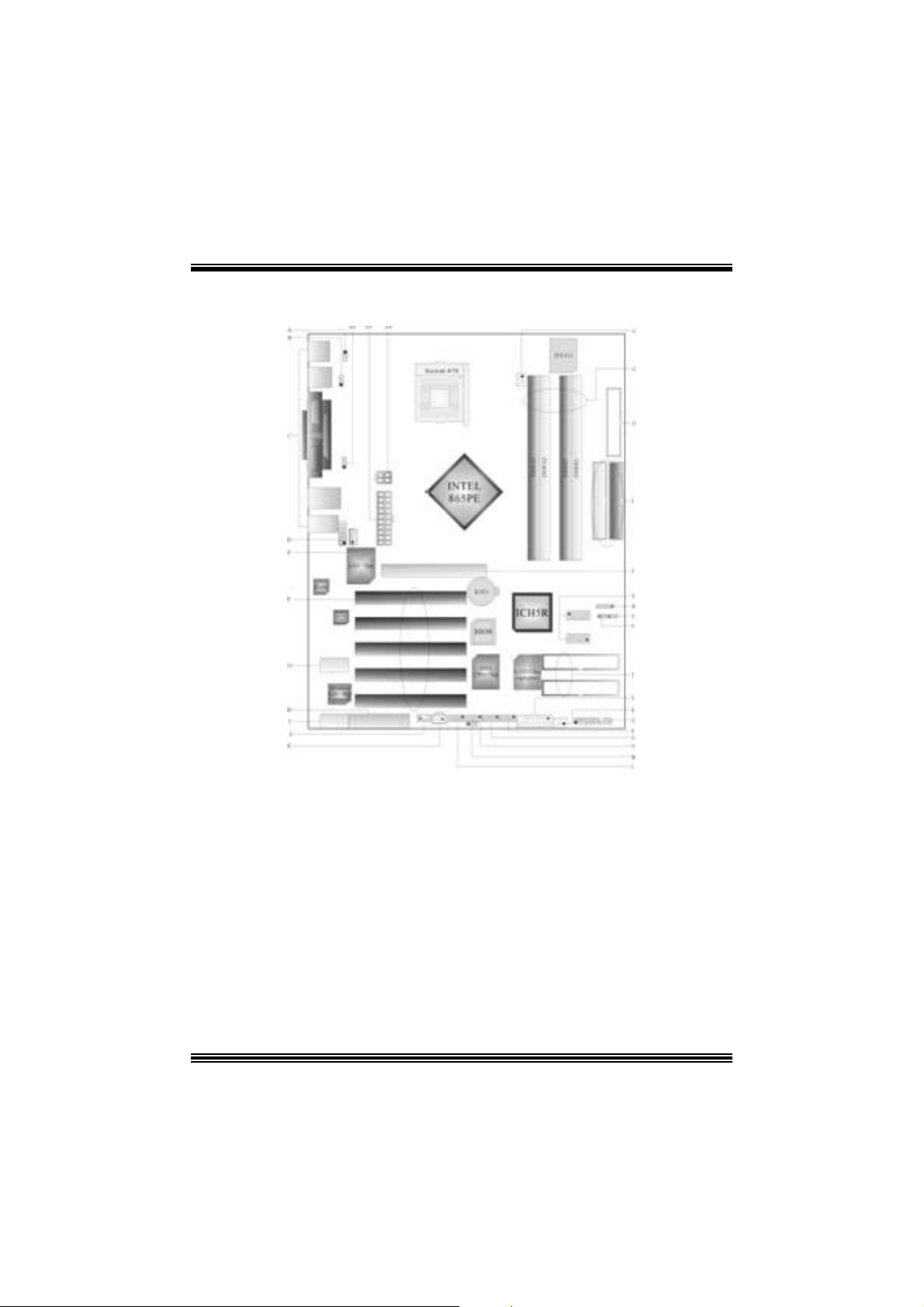
Co mponent Index
A. JKBV1: Po wer Source Selection for
Keyboard/ Mouse
B. JUSBV 1: Po wer Source Selection for USB R. JSF AN1 : System F an Header
C. Back Panel Connectors S. JGAME1: Gam e Header
D. JAUDIO 1: Front Audio Header T. RAID1-2: Raid Connectors
E. PCI 1-5 : Peripher al Component
In ter conn ect Slots
F. JCDIN1: CD-ROM Audi o -In Header V. JCMOS1: Clear CM OS Jumpe r
G. U43: Wire less Audio Connector W. JDJ1: Audio DJ Connector
H. CNR1: Co mmunic ation Network Riser Sl o t X. SATA1-2: Serial ATA Connectors
I. U33: Wi reless LAN Connector (optional) Y. AGP1: Accelerated Graphic Port Sl ot
J. JW OL1: W ake On LAN H eader Z. IDE1-2: Hard Disk Connectors
K. JSPDIF_OUT1: Digita l Audio Connector A1. FDD1: Floppy Disk Connector
L. JUSB2: Front USB Header A2. DDRA1-2/ DDRB1 -2: DDR DIMM Modules
M. JUSBV 3_4: Po wer Source Selection for
USB
N. JUSB3: Front USB Head er A4. JA TXPWR2: ATX Power Conne ctor
O. J139 4A1: Front 1 394 Header A5. J ATXPW R1: ATX Po wer Connector
P. J1394B1: Front 1394 Header A6. JUSBV2: 5V /5VSB S election for USB
Q. J PANEL1: Front Panel Connector
U. JCL1: Case Op en Connector
A3. JCFAN1: CPU Fan Connector
2
English
P4TSE Pro Featu res
A. Har dware
CPU
Pr ov ide s S o cke t-478 .
Supports the Int el Pent ium 4 proces s or to 3.6 GHz+.
F ront Side Bus at 400/533/800MHz.
Su pports Hyper-Threading.
Support s Nort hwood and Prescott CPU. (W illamet t e not suppor ted)
Chipset
N orth Bridge: Intel 865PE.
South Bridge: Int el ICH5R.
Main Me m o ry
Supports one or two 64-bit wide DDR data channels with 1 or 2 DIMMs
per-channel.
Av ailable bandwidt h up t o 3.2GB/s (DDR400) for single-channel mode and 6.4GB/s
(DDR 400) in dual channel mode.
Supports 128-MB, 256-Mb, 512-Mb DDR technologies .
Supports o nly x8, x16, DDR d evice s.( Doe s no t support r egis tered DIMMs)
Supports four bank devices.
Maxi mu m me mo ry s i ze is 4GB.
Super I/O
Chip: ITE IT 8712.
Low Pin C ount Int erface.
Prov ides the most commonly used legacy Super I/O f unctionality.
Env iro nm ent C ont rol i niti atives ,
- H/W Monitor
- Fan Speed Controller
- I TE's "Smart Guardian" f unction
Slots
F ive 32-bit PCI bus mas t er s lots.
On e CN R slo t .
One AGP 4X/8X slot.
On Board IDE
Supports four IDE di s k dri ves.
Supports PIO Mode 5, Bride Mode and U lt ra DMA 33/66/100 Bus Mast er Mode.
Supports 2 Serial ATA (SATA) ports.
- C om pliant wit h SATA 1.0 specif ic ation
3
- Data transfer rates up to 1.5 Gb/s
LAN
Chip: RTL8 100B.
Supports 10 Mb/s and 100 Mb/ s auto-negot iat ion
Hal f/Full du plex cap ability.
Supports ACPI power m anagement
IEEE 1394A Chip
C hip: VIA VT6307.
Support 2 ports with transfer up to 400Mb/s.
Ser i al AT A/R AI D
Chip: ICH5R wi th Intel® RAID T e ch n ology.
Support RAID 0 (s triping).
Optimize dat a t ransf er rates for dis k-intens ive applicat ion.
Inte l ® 82801 ER I/O Controller
Dual Serial ATA C ont rollers with
Intel Application Accelerator RAID
On Bo ard AC’97 Sound Cod ec
Chip: C MI9739A/ 9760.
Compliant with AC ’97 s pec ificat ion.
AC 97 2. 2 interf ac e.
Support s 6 c hannels.
On Board Periphera ls
a. R e ar si de
2 s erial port s.
1 parallel port. (SPP/EPP/ECP m ode)
Audio ports in v ert ical posit ion.
1 R J -45 LAN jack.
Support s PS/ 2 mous e and PS/ 2 keyboard.
4 USB2.0 por t s.
1 1394A Firewire ports.
Features Benefits
Hub
RAI D 0 Support
RAI D BI OS ROM Int egrat ed into system BIOS, enables pre-OS
RID Migratio n Ca pability Seamless m igration f rom a sing le hard drive to
Ed ition
Industry’s first desktop RAID controller
integrat ed directly into the chipset
Exc eptional storage perf orm ance utilizing the
next -generation hard disk interface t echnology
RAID creation, naming and deletion
a RAID 0 array with no OS reinstallation
required
Driver wit h full m anagement and s t atus
reporting of y our RAID array including detailed
reporting of storage devices
4

b. F ront Si d e
1 floppy port supports 2 F DDs with 360K, 720K, 1.2M, 1.44M and 2. 88Mby tes.
4 USB2.0 port s.
1 front audio header.
1 S/PDIF header.
1 1394A Firewire port s.
Dimensions
ATX F orm Factor: 24.4 X 30.5cm (W X L)
B. BIOS & S oftware
BIOS
Award legal BI OS.
Support s APM1.2.
Support s AC PI.
S upports USB Func tion.
Software
Supports Warpspeeder™, 9t h Touch™, FLASHER™ and StudioFun! ™.
Offers the highest performance for Windows 98 SE, Windows 2000, W indows Me,
Windows XP, SC O UNIX etc.
Package contents
HDD Round C able X 1
FDD Round C able X 1
User’s Manual X 1
Fully Setup Driver CD X 1
St udioF un! Application CD X 1
USB 2.0 Cable X 1 (optional)
S/ PD IF Cable X 1
Rear I/ O Panel for Mic ro ATX C as e X 1
Serial ATA C able X 1
Se rial AT A Po w er Sw it c h C able X 1
IEEE 1394 C able X 1 (optional)
5
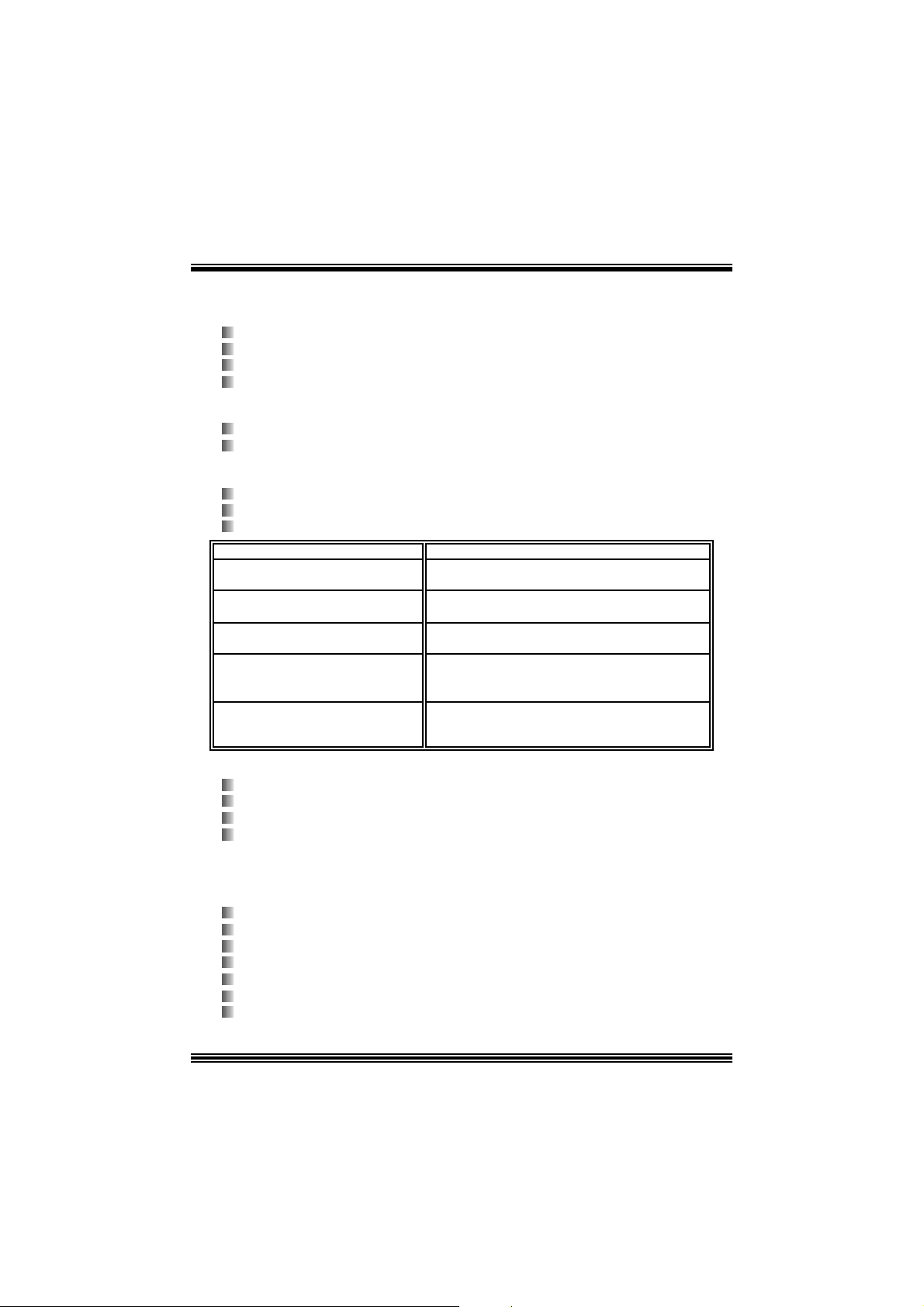
How to s e t u p Jumper
The illustration s hows to how set up jumper. When the J umper cap is placed on pins, the
jumper is “close”. IF no jumper cap is placed on the pins, the jumper is ”open”. The
illust rat ion shows a 3-pin jum per whose pin1and 2 are “close” when jumper c ap is placed
on thes e 2 pins .
Jumper open Jum per close Pin1-2 close
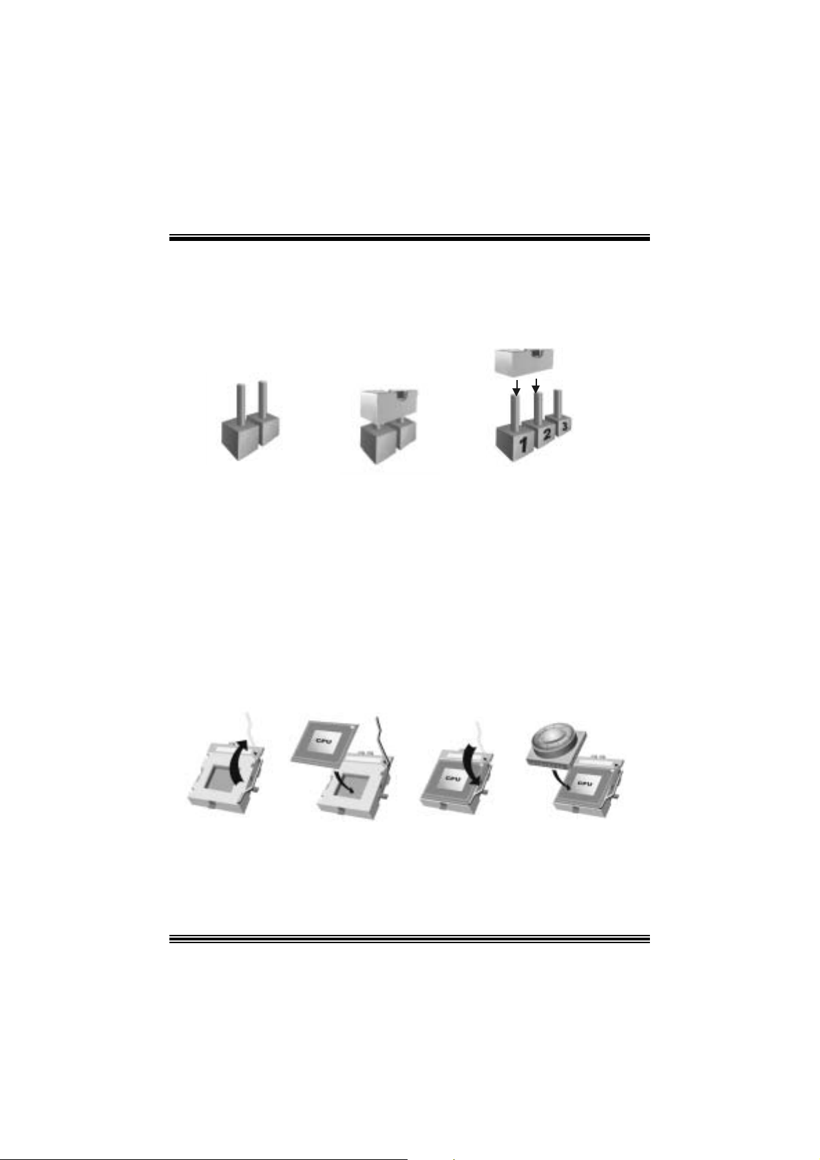
CPU Installation
Step1: Pull the lever sideway s away from the socket and then raise the lev er up to a
90 -degree angl e.
Step2: Look for the whit e dot /cut edge. The whit e dot/ cut edge should point wards the lever
piv ot. The C P U will f it only in the correct orient at ion .
Step3: Hold the CPU down fir mly, an d then cl ose the lever to complete the installation.
Step4: Put the CPU Fan on the C PU and buck le it. Connect the C PU fan power cable to
the JCFAN1. This completes the installation.
Ste p 1 Step2 Step3 Step4
6
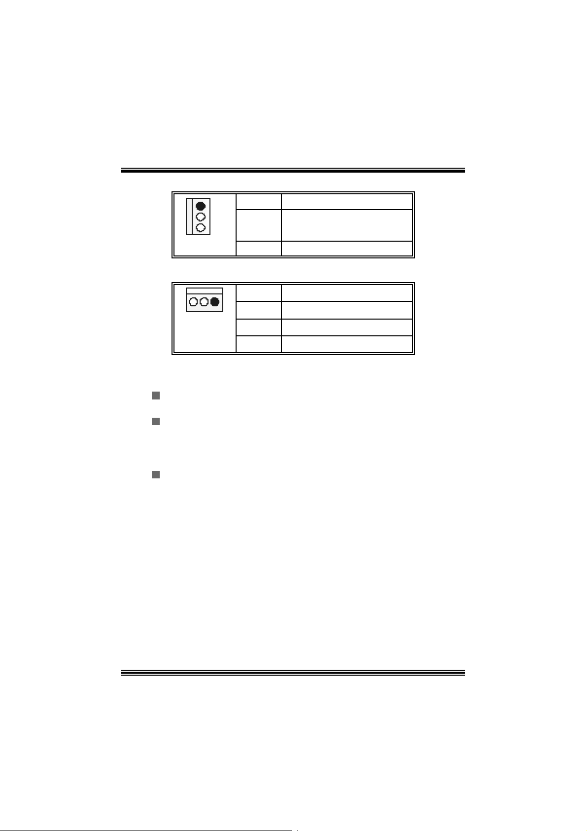
CPU Fan Headers: JCFAN1
1
JCFAN1
Pin Assignment
1
2
3
Ground
+12V
FAN RPM rate Sense
S ystem Fan Headers: JSFAN1
Pin Assignment
1
JSFAN1
1
2
3
Ground
+12V
FAN RPM rate Sense
DDR DI MM Module s: DDRA1- 2, DDRB1-2
Support s up to four DD R DI MMs(two DI MMs per channel), single-s ided and/ or
double-sided.
F or Dual Channel Operat ion, DI MMs must be populated in identical pairs. It
has to be t he com bination of DDR A1+DDR B1 (Blue DI MMs) or DDRA2+DDRB2
(white DIMMs).
Dual Channel Guidelines
Matc hed DI MM configurat ion in eac h channel
% Same Dens ity (128MB, 256MB, 512MB, 1GB, etc.)
% Same DR AM t echnology (128M-bit, 256M-bit , or 512M-bit)
% Same DR AM bus width (x8 or x16)
% Both either s ingle-sided or dual-s ided
Matc hed in both Channel A and Channel B mem ory channels
% Populate symmetrical memory slots
Opt im al platform performance with Dual C hannel, D DR400, m atched DIMMs
% Fully loaded conf igurat ions can be single or double sided DI MMs
% Light ly loaded c onf igurations need to be double sided DIMMs
When not using DDR400, best performance obtained with
7

% Symm et rical DI MM population and m atched double-s ided DIMMs
% Light ly loaded c onf iguration
Dual Channel Configura tion Table
Dual C hannel Configuration Table
•
DIMM Slot DDRA1 DDRA2 DDRB1 DDRB2 System
Density
Lightly Loaded
Config
Lightly Loaded
Config
Fully Loaded
Config
DRAM Acces s Time: 2.5V Unbuffered/ no regis tered (without ECC) DD R SDRAM
DRAM Ty pe: 128MB/ 256MB/ 512MB/ 1GB DI MM Module (184 pin)
128MB -1GB
128MB --
128MB -1GB
PC2100/ PC 2700/ PC 3200 Type required.
128MB --
1GB
128MB --
1GB
128MB --
1GB
128MB -1GB
256MB --
1GB
128MB --
1GB
Installing DDR Module
1. Unloc k a DIMM slot by pressing the retaining clips
o ut wa rd. Ali gn a D I MM on t h e sl ot s uc h t hat t he
notc h on the DIMM matches the break on the slot.
2. Ins ert the D IMM vertically and f irm ly into the s lot
until the retaining chip snap back in place and the
DIMM i s properly seated.
Jumpers, Headers, Connectors & Slots
2GB
256MB --
2GB
512MB --
4GB
Floppy Disk Connector: FDD1
The mot herboard provides a standard f loppy disk connector that supports 360K,
720K, 1.2M, 1.44M and 2.88M floppy disk types. This connector supports the
prov ided f loppy drive ribbon cables .
Hard Disk Connectors: IDE1/ IDE2
The motherboard has a 32-bit Enhanced PCI IDE Controller that provides PIO
Mode 0~5, Bus Mast er, and U ltra DMA 33/ 66/ 100 f unctionality. I t has two H DD
connectors ID E1 (primary) and IDE2 (secondary).
8

The ID E c onnectors can c onnect a master and a slav e driv e, so you c an connect
up to four hard disk drives . The f irst hard drive s hould alway s be c onnected t o
IDE1.
Periphera l Component Int erconnect Slots: P CI1-5
This m ot herboard is equipped with 5 st andard PCI s lots. PCI stands for Peripheral
Component I nterconnec t, and it is a bus standard for expansion cards. This PCI
slot is des ignated as 32 bits.
Accelerate d Graphics Port Slot: AGP1
Your monitor will attach directly to that video card. This motherboard supports
video cards f or PC I s lots, but it is als o equipped with an Accelerated Graphics Port
(AGP). An AGP c ard will take advantage of AGP technology f or improv ed video
efficiency and perform ance, es pecially with 3D graphics.
Commun ication Netwo r k R ise r Slot: CNR1
The CNR specification is an open I ndust ry St andard Architecture, and it def ines a
ha rdw ar e scalable r iser card interfa ce, which su pports modem only.
Serial ATA Co nnector: JSATA1/JSATA2
The mot herboard has a PCI to SATA C ontroller with 2 channels SATA int erf ace, it
satisfies the SATA 1.0 spec and can transf er data wit h 1. 5GH z s peed.
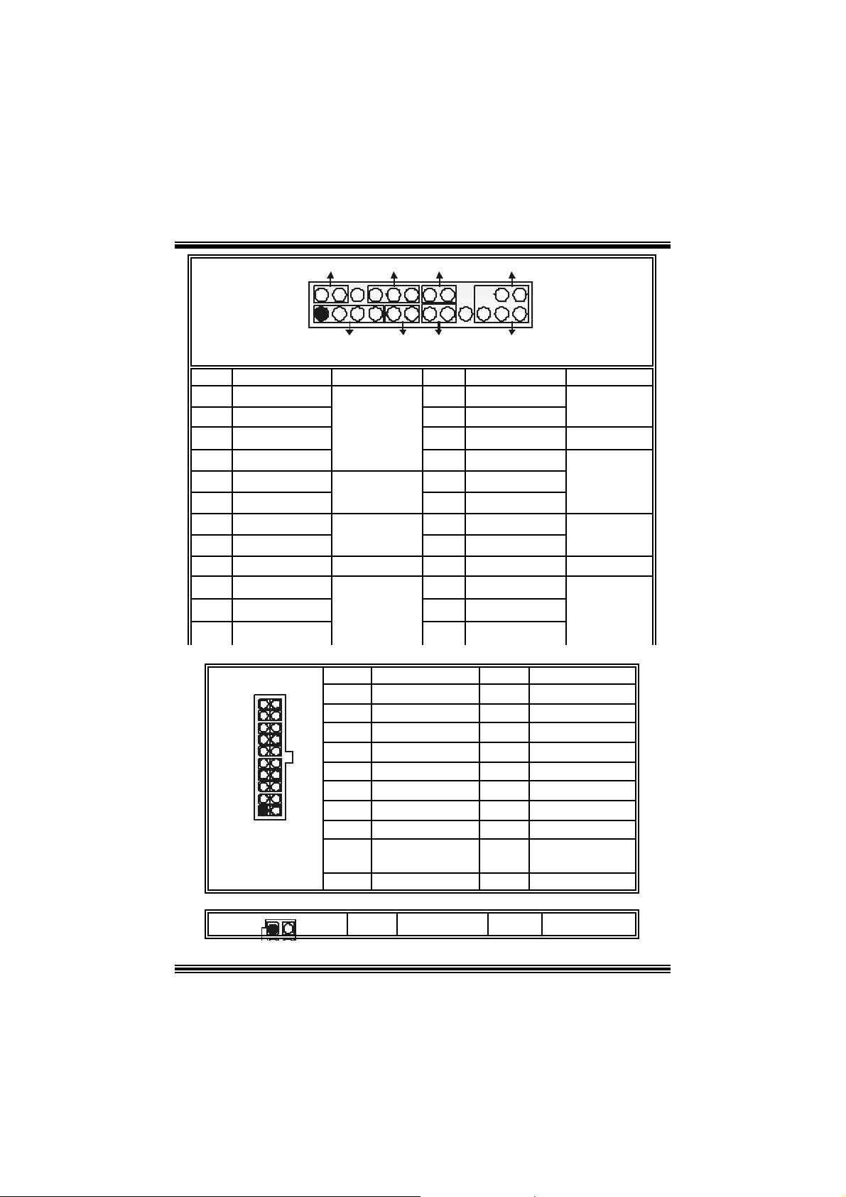
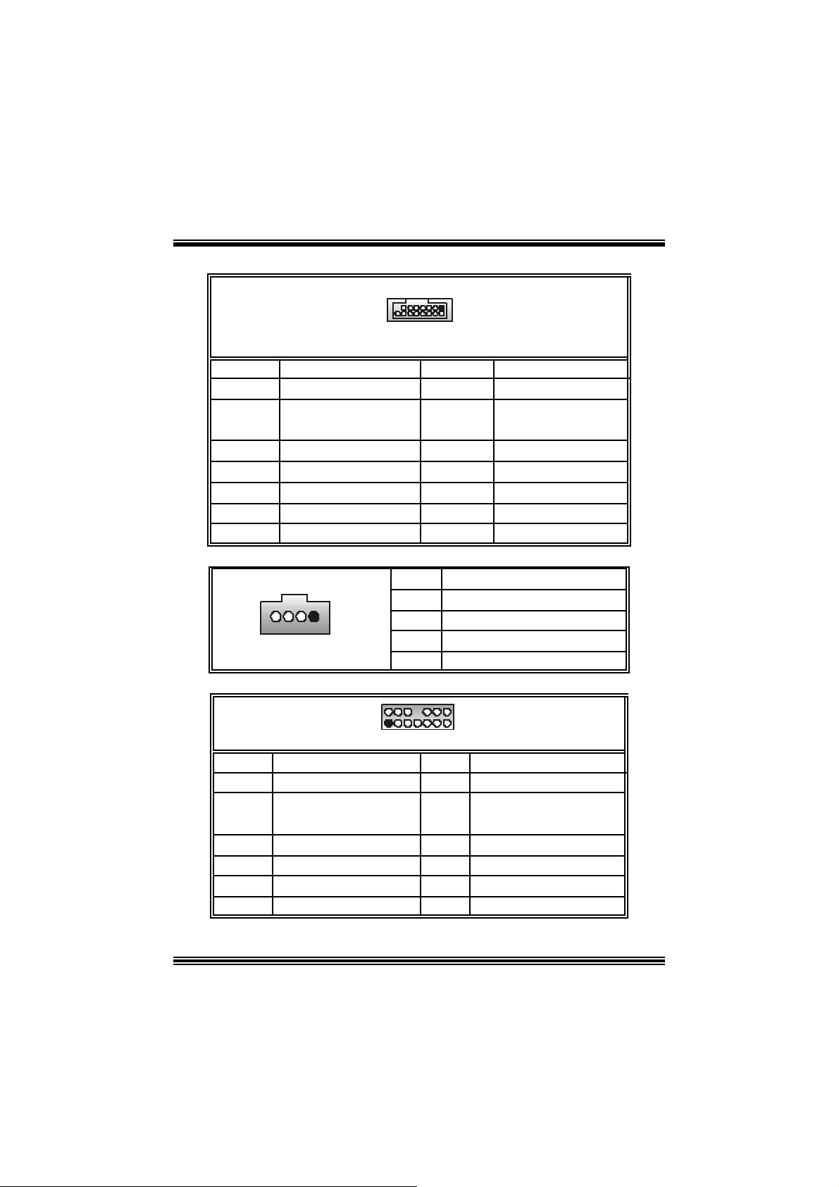
Front Pane l Conne ctor: JPANEL1
9
SLP
JPANEL1
Pin Assignment Function Pin Assignment Function
1 +5V 2 Sleep Control
3 NA 4 Ground
5 NA 6 NA NA
7 Speaker
9 HD D LED (+ ) 10 Power LED (+)
11 HDD LED (-)
13 Ground 14 Power But t on
15 Reset Control
17 NA 18 KEY
19 NA 20 KEY
21 +5V 22 Ground
23 IRTX
2
1
PWR_LED
SPK
Speaker
Connector
Hard Drive
LED
Reset
Button
IrDA
Connector
HLED
RST
8 Power LED (+)
12 Power LED (-)
16 Ground
24 IRR X
IRON/OFF
IR
24
23
Sleep
Button
POWER
LED
Power-on
Button
IrDA
Connector
Power Conn ectors: JATXPWR1/ JATXPWR2
PIN Assignment PIN Assignment
1
2
3
4
5
6
7
8
9
10
PIN Assignment PIN Assignment
+3.3V
+3.3V
Ground
+5 V
Ground
+5 V
Ground
PW_OK
Standby Volt age
+5 V
+12V
11
12
13
14
15
16
17
18
19
20
+3. 3V
-12V
Ground
PS_ON
Ground
Ground
Ground
-5V
+5V
+5V
10
1
JATXPWR1
13
20
11
10
1
2
+12V
+12V
3
4
Ground
Ground
Power Source Selection for Keyboard/ Mo use: JKBV1
JKBV1 Assignment Description
1
3
Pin 1-2 c los e
1
3
Pin 2-3 c los e
+5 V
+5V Standby
Voltage
+5V for keybo ard and mouse
PS/2 Mous e and PS/2 Key board are
powered with +5V standby v oltage
No te: In or der to po wer- on ke ybo a rd an d mous e fu ncti on , “JKB V1 ” jump e r
cap should be placed on pin 2-3.
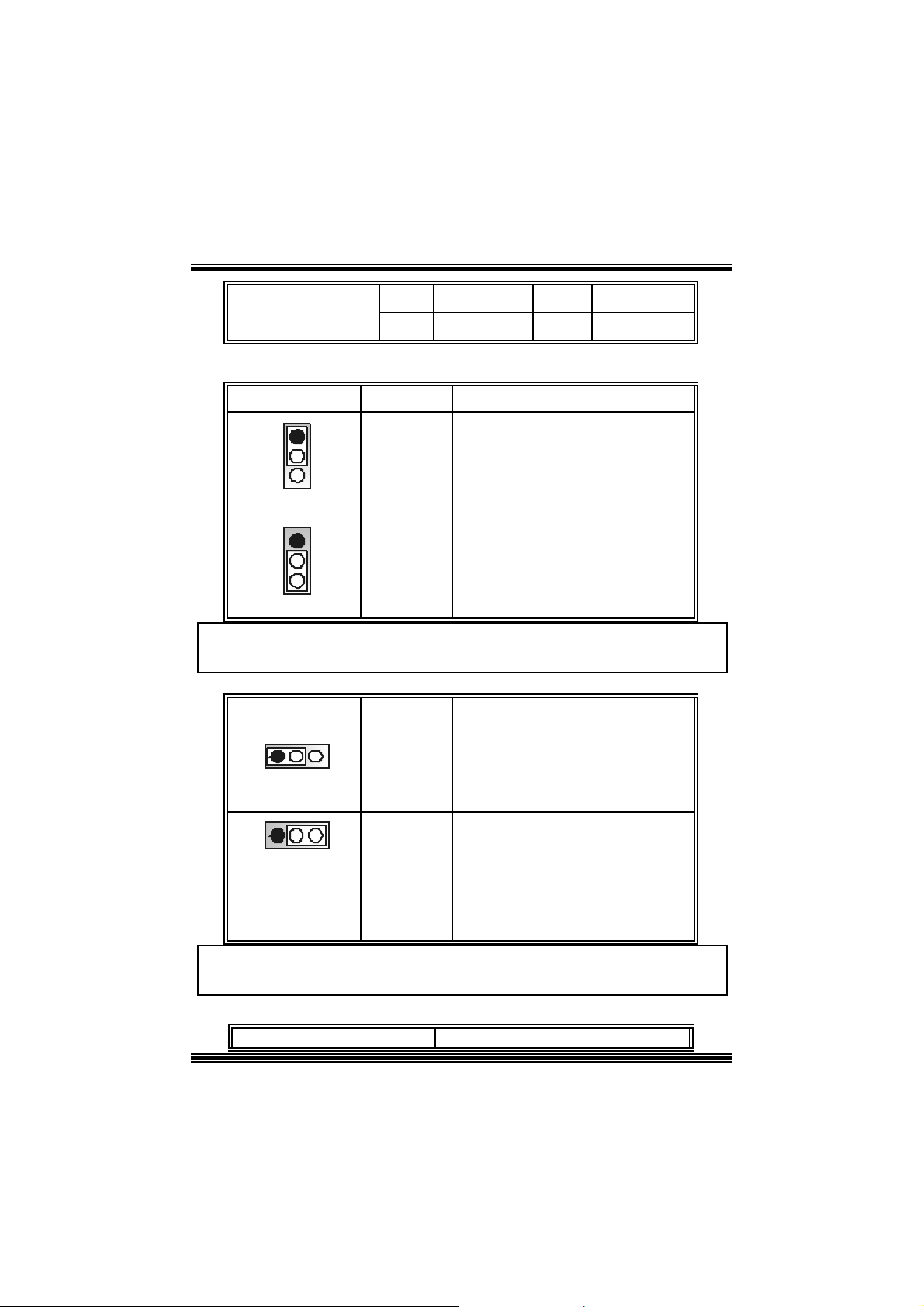
Power Source Selection for USB: JUSBV1/ JUSBV2/ JUSBV3_4
JUSBV1/JUSBV2/
JUSBV3_4
Assignment Description
1 3
Pin 1-2 c los e
1 3
Pin 2-3 c los e
+5V Standby
+5 V
Voltage
JUSB V1: 5V for JUSB 1 port
JU SBV2: 5V for JRJ45U SB1 port
JUSBV 3_4: 5V for JUSB2/3 por ts
JU SBV1: JUSB1 port powered with
standby v olt age of 5V
JU SBV2: JRJ 45USB1 port powered
with s t andby v olt age of 5V
JU SBV3_4: JUSB2/3 ports powered
with s t andby v olt age of 5V
Note: In order to power-on USB devices function, “JUSBV1/JUSBV2/
JUSBV3_4” jumper cap shoul d be placed on pin 2-3 i ndi vidually.
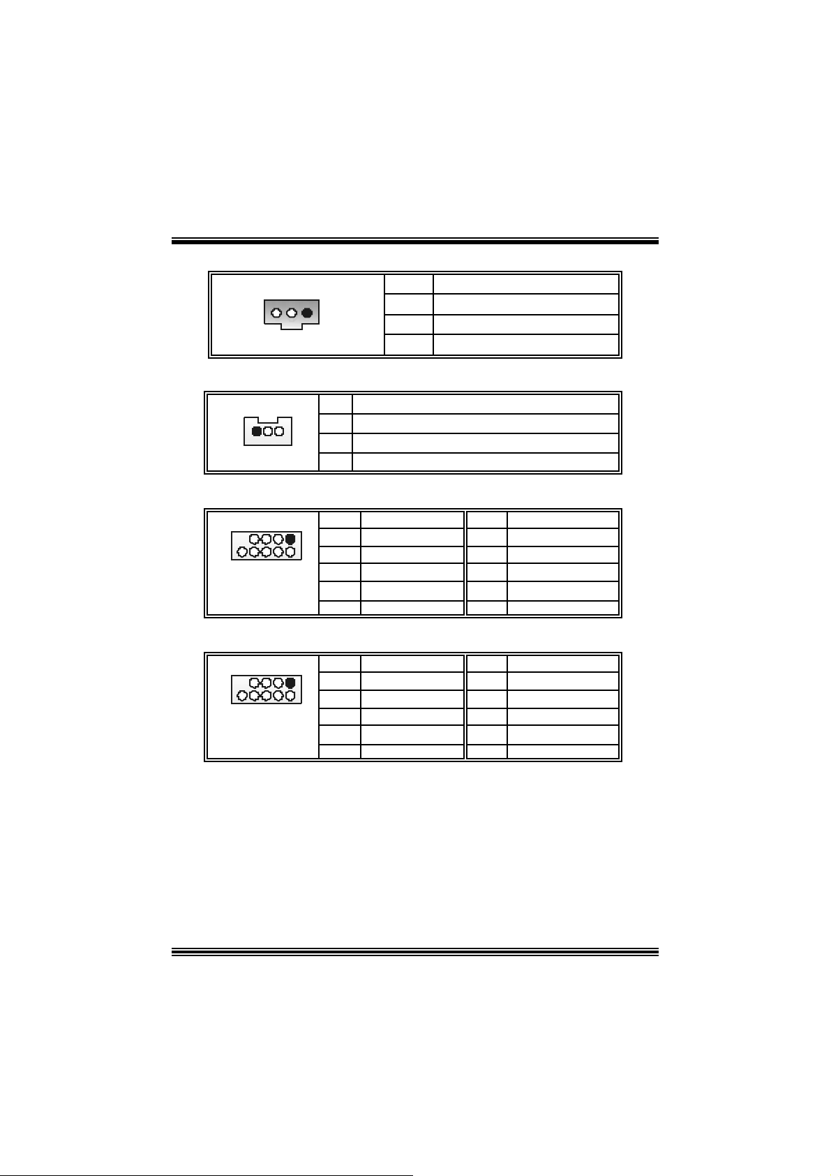
Clear CMOS Jumper: JCMOS1
JCMOS1 Assignment
11
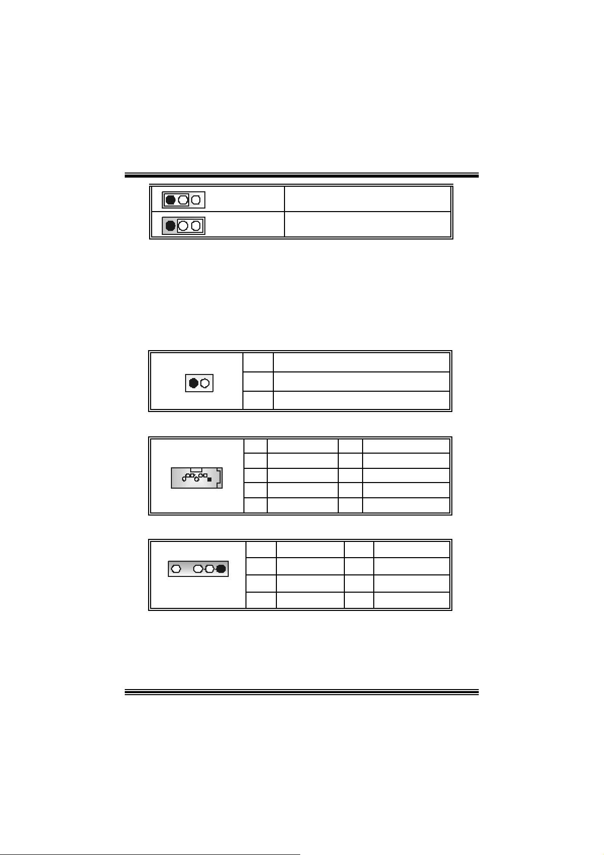
1 3
1 3
Pin 1-2 C lose
Pin 2-3 C lose
Norm al Operation (def ault)
Clear CMOS Data
※ Clear CMOS Procedures:
1. R emov e AC power line.
2. Set the jumper to “Pin 2-3 C lose”.
3. Wa it for fi ve seconds.
4. Set the jumper to “Pin 1-2 C lose”.
5. Power on t he AC .
6. R eset your des ired password or clear t he C MOS dat a.
Ca se Op e n Connec to r: JCL1
1
2
JCL1 2
Pin
1
Assign ment
Case Open Signal
Ground
Serial ATA Co nnector: JSATA1/ JSATA2
1234567
JSA TA1/ JSATA2
Pin Assignment Pin Assignment
1
4
5
7
Ground
TXRX-
Ground
2
4
6
AUDIO DJ Connector: JDJ1
TX+
Ground
RX+
JDJ1
Pin Assignment Pin Assignment
1
15
3
5
SMBDATA
INT_B
ATX_PWROK
12
2
4
SMBCLK
KEY
Game Header: JGAME1
JGAME1
1
216
2
4
6
8
10
12
14
16
GPSA1
Ground
Ground
GPSA2
15
Pin Assig nment Pin Assignment
1
3
5
7
9
11
13
15
+5V
GPSB1
GPX2
MI D I-OUT
GPY2
GPSB2
MIDI-IN
NA
CD-ROM Audio-In Heade r: JCDIN1
1
JCDIN1
Pin Assignment
1
2
3
4
Left Channel In put
Ground
Ground
Right Channel In put
Front Panel Audio Header: JAUDIO1
+5V
GPX1
GPY1
+5V
2
1
JAUDIO1
Pin Assignment Pi n Assign m ent
1
3
5
7
9
11
13
Mic In
Mic Po we r
RT Line Out
Reserved
LFT Line Out
RT Line I n
LET Line In
13
14
13
2
4
6
8
10
12
14
Ground
Audio Power
RT Line Out
Key
LFT Line Out
RT Line In
LET Line I n
Digital Audio Connector: JSPDIF_OUT1
1
JSPDI F_OUT1
Pin Assignment
1
2
3
Wake On LAN He ader: JWOL1
+5V
SPDIF_OUT
Ground
1
JWO L1
Pin Assignment
1 +5V_SB
2
3 Wake up
Ground
Front USB Header: JUSB2/3
Pin Assignment Pin Assignment
1
1
3
2
5
7
9
+5V(fused)
USB-
USB+
Ground
KEY
9
10
JUSB2/3
Front 1394 Header: J1394A1/ J1394B1
9
10
J1394A1/ B 1
Pin Assignment Pin Assignment
1
1
3
2
5
7
9
A+
Ground
B+
+12V
KEY
2
4
6
8
10
2
4
6
8
10
+5V(fused)
USB-
USB+
Ground
NC
A-
Ground
B-
+12V
Ground
14
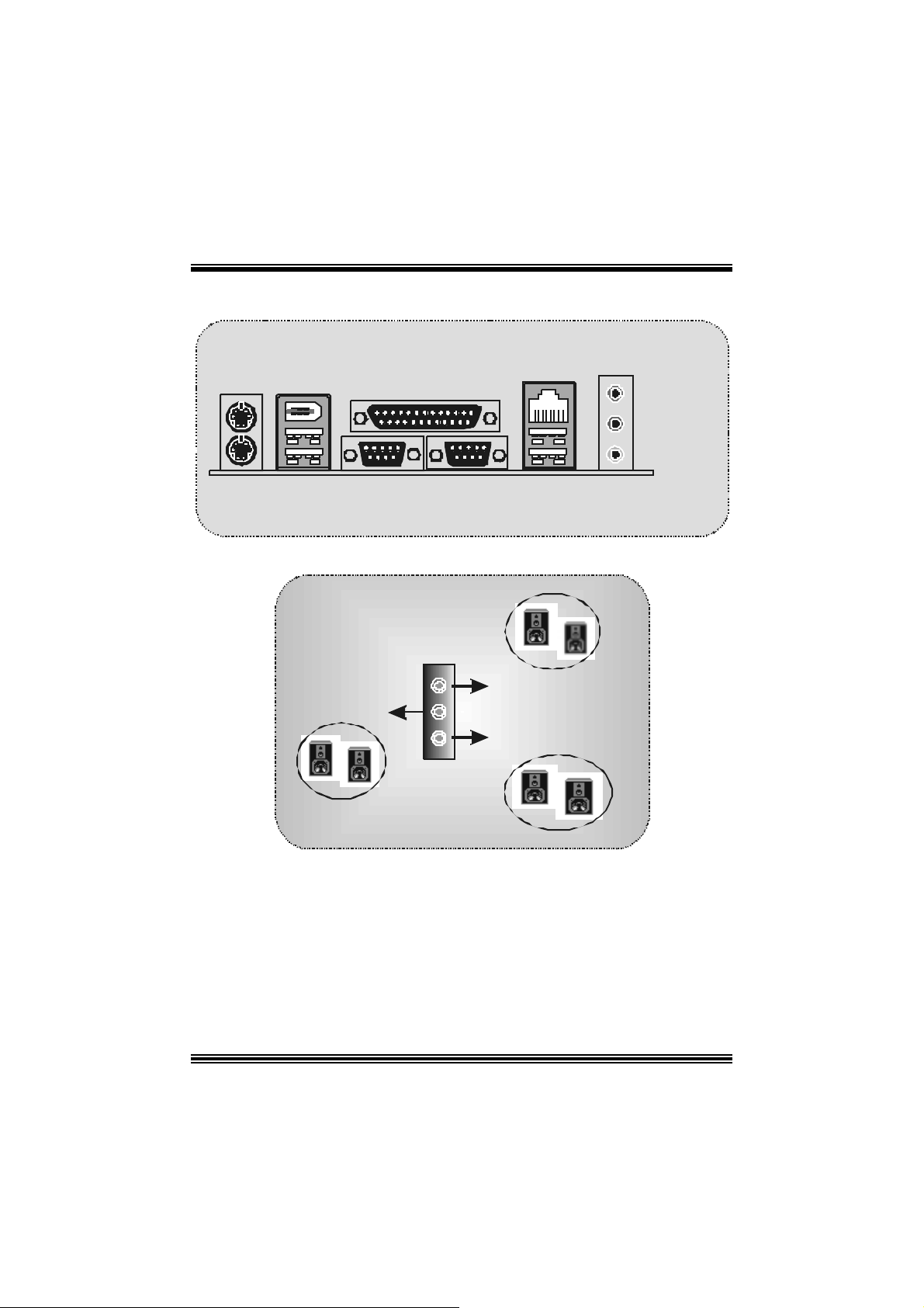
B ack Panel Connectors
JKBMS1
PS/2
Mouse
PS/2
Keyboard
J1394_USB1
JPRNT1
1394
USB
Parallel
COM1
JCOM1
6 Channel Speakers
Spe aker Out
JRJ45USB1
LAN
COM2 US B
JCOM2
Li n e In / Rear Speake r
Mic I n / Cen ter & Bass
Line In
Speaker Out
Mic In
JAUDIO
15
StudioFun!
Introduction
StudioF un! is a media-player based on optimized GNU/ Linux distribution. It play s D VD,
VCD , MP3, Audio CD and various other k nown file f ormats. You can tak e s naps hots of
video and customize the saved images as screens avers. Y ou can also store the images
on USB mass storage dev ices lik e f lash disks and USB f loppy disks.
Hardware Requirements
The supported hardware list of StudioFun! grows up every day. So please check the
hwreq.txt located in the root of StudioFun! Installation CD to get the most updated
information.
Ins tallatio n Proce dure
Ins ert the StudioFun! Installation CD in a CD/DVD ROM drive and let the system boot
through the CD. The dis k will boot and bring up the grub boot loader installation menu.
Two opt ions are specif ied.
16

Installation
This option will do the basic installation of the distribution. The installation works on
pre-inst alled windows or GNU / Linux dist ribution.
On select ing the ’installat ion’ option the inst aller boots and display s a dialog box indicat ing
the s pace required and waits f or a confirmation. Selecting Ok will c ontinue the inst allat ion
while select ing Canc el will t erm inate t he installation and reboot the mac hine.
If Windows or GNU/Linux is the only OS installed on the hard disk wit h no f ree space, it
will resize the partit ion, eit her NTFS or FAT32 or ex t 2, and install StudioFun!. I n case t he
hard dis k has a 128MB of free s p ace av ailable, t he installatio n will us e the f ree spac e.
Aft er installing the base system y ou will be prompt ed to select the res olution f rom the
following choice s
1. 1024x768 (rec om m ended)
2. 800x 600
3. 640x 480
Select the desired res olut ion. The default is 1024x768 for high-end graphic s.
Nex t y ou will be prompted t o c hoose t he DVD area/region s elec tion code. Choose t his
bas ed on the ty p e of D VDs y ou will b e playing.
The installation procedure will then probe for the type of mouse installed. The distribution
currently supports PS/2, USB and Serial mice. In case of serial m ouse you will hav e to
mov e the mouse when prompt ed. The ot her two are probed and inst alled automatic ally.
The installation procedure will now finish, the CD is eje c ted and a dialog box prompting to
reboot t he m achine is dis play ed. Pres s OK butt on and enjoy StudioFun!.
3.1.1 Error Messages
1. Media c orrupted!! Pleas e check the media! The CD -RO M is corrupt ed.
2. Extract ion of base sy s tem failed!! Pleas e try again later!! The C D -ROM is corrupted.
3. Unsupported hardware found, Aborting... If you try to install StudioFun! on an
unsupported and undocumented hardware the abov e error m ess age is popped.
4. N o device found! This error message is given if t here is no hard disk in the sy stem.
17
Recovery
In c ase of a MBR c orruption, this option should be us ed. It will aut omatically probe the
hard disk m aster boot record and f ind out the inst alled operat ing system(s ). On succ ess it
will re-inst all the boot loader with correct options in the MBR. Any c ustom boot loader
option specified from other GNU/Linux installations will get over written by the newly
probed one.
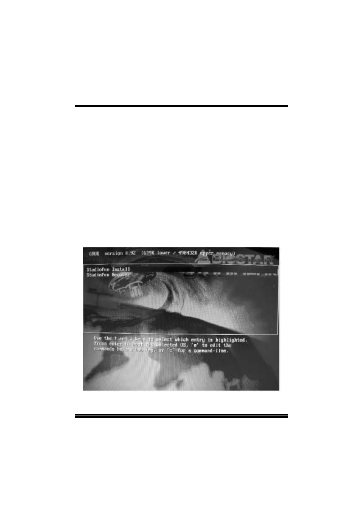
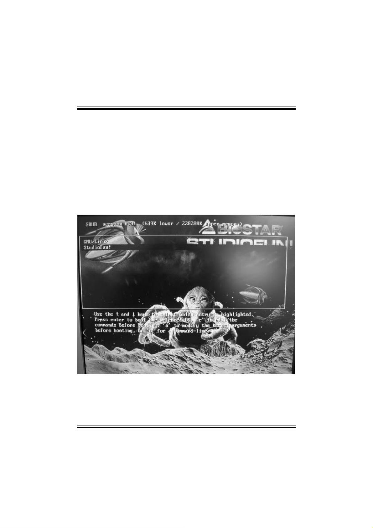
B o oting to S t udioF un!
After Installation is ov er, rem ove the CD f rom the CD-ROM and restart the machine. After
the machine reboots, you will get the GRUB boot loader menu screen. Select the
StudioF un opt ion to boot to the St udioFun! partition.
18
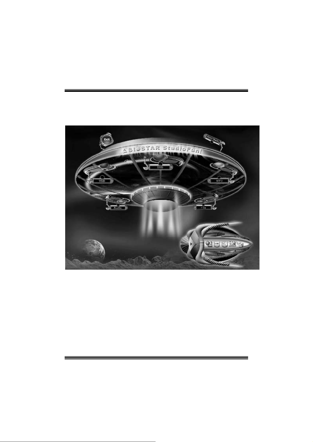
After comple te bo ot up, you get to th e main Des ktop screen. Th e followi ng section is
a com plete descript ion of the Desktop applicat ion.
Desktop
This is t he m ain shell of t he StudioFun s of t ware. It basic ally com prises of two cat egories ,
one is the main "media control" part and t he other is the "control panel".
Media control
The media c ontrol part of t he D eskt op has the following cont rols:
1. VCD
This c ontrol will glo w whenev e r a VCD is d etected in a DVD/CD-R OM drive. The VCD will
be auto-play ed only when it is put in to the drive when the Desktop (StudioF un! shell) is up
and running, otherwise, the control will simply glow to inform the user about a VCD
19

present in t he DVD/CD-ROM driv e.
2. DVD
This control will glow whenever a DVD is detected in a DVD drive. The DVD will be
auto-played only when it is put in to the driv e when the D esktop (StudioF un! shell) is up
and running, otherwise, the control will simply glow to inform the user about a DVD
present in t he DVD/CD-ROM.
3. MP3
This c ontrol will glo w whenev e r a MP3 is detected in a DVD/CD-R OM drive. The MP3 will
be auto-play ed only when it is put in to the drive when the Desktop (StudioF un! shell) is up
and running, otherwise, the control will simply glow to inform the user about a MP3
present in t he DVD/CD-ROM driv e.
4. AUDIO
This control will glow whenev er a AUDI O is detected in a DVD /CD-R OM driv e. The AUDI O
will be auto-play ed only when it is put in t o t he driv e w hen the Desktop (StudioFun! shell)
is up and running, ot herwise, the control will simpl y glo w to inf orm the user about a AUDI O
present in t he DVD/CD-ROM driv e.
5. FILE
This co ntrol will glow whenever a File C D (CDs with other media type files) is det ect ed in a
DVD/CD-ROM drive. The File CD will be auto-play ed only when it is put in to the driv e
when the D esktop (StudioFun! shell) is up and running, otherwise, the control will simply
glow to inform the user about a F ile CD present in t he D VD/CD -R OM driv e.
6. EJECT MEDIA
This cont rol when c lick ed will ejec t any MP3 or File CDs f rom any of the DVD/C DR OM
driv es. In case there were no MP3 or File CDs it will eject the def ault medium, (i.e.), the
CD -ROM driv e in c ase if the user has both D VD/ CD-ROM driv e or else it will eject the
default DVD /CD-ROM drive .
7. EXIT
This is the "Power on/ off" control of the D esktop (StudioFun! shell).
Co nt ro l Pa nel
Cont rol panel part has five icons, which are shortcuts t o other applic at ions pres ent in t he
StudioFun sof tware. Tool tips are provided on t he icons when the m ous e is rolled over
them.
20
 Loading...