

Page 1

P
i
D
T
4
P
D
T
4
P
Q
Q
V
-
V
-
V
-
Q
D
T
4
FCC Infor mation and Copyright
T hi s equi pm ent h as b een te ste d and fo und to c ompl y wi th th e lim its o f a
Class B digital device, pursuant to Part 15 of the FCC Rules. These limits
are designed to provide reasonable protection against harmful interference
in a residential installation. This equipment generates, uses and can
radiate radio frequency energy and, if not installed and used in accordance
with the instructions, may cause harmful interference to radio
communications. There is no guarantee that interference will not occur in a
pa rticu lar ins ta llat ion.
The vendor makes no representations or warranties with respect to the
contents here of and specially disclaims any implied warranties of
merchantability or fitness for any purpose. Since our products are under
continual improvement, we reserve the right to make changes without
notice.
The material in this manual is the intellectual property of the vendor.
Further the vendor reser ves the r i ght to re vise this publ ic ation and to m ake
changes to its contents without obli gation to notify any party beforehand.
Dupli cation of thi s publication, in part or in whole, is not allowed without
first obtaining the vendor’s approval in writing. Even thought we have
taken every care in the preparation of this user’s manual, no guarantee i s
given as to the correctness of its contents.
All the brand and product names are the property of their respective
owners.
Page 2

T
T
T
o
e
l
b
a
e
l
b
a
n
o
C
f
n
o
C
f
o
s
t
n
e
t
s
t
n
e
t
s
t
n
e
t
n
o
C
f
o
e
l
b
a
Layout of P4TDQ-V ( only for version 1.x).........................1
Layout of P4TDQ-V ( only for version 7.x).........................2
English ............................................................................3
1. P4TDQ-V F eatures..................................................................................3
2. Package contents ...................................................................................4
3. How to setup Jumper..............................................................................5
4. CPU Installation......................................................................................5
5. DDR DIMM Modul e s: DIMM1 / DIMM2 . .........................................................6
6. Ju mp ers, Headers, Conn ectors & Slots .....................................................7
StudioFun!TM.................................................................12
Introdu ction.............................................................................................12
Hardware Re quire m e nts.......... ........................ ........................ ..................12
Installation Procedure...............................................................................12
Booting to StudioFun!.............................................................................. 14
Media control.......................................................................................... 15
Control Panel..........................................................................................16
Sof t wa re Det ails......... ........................ ........................ ..............................17
Select R egion..........................................................................................20
Screensaver............................................................................................ 20
Display Settings.......................................................................................22
File Manager............................................................................................ 22
WarpSpe e der.................................................................24
Introdu ction.............................................................................................24
System Requ irement................................................................................24
Installation ..............................................................................................25
Usage.....................................................................................................26
Trouble Shooting............................................................34
ii
Page 3
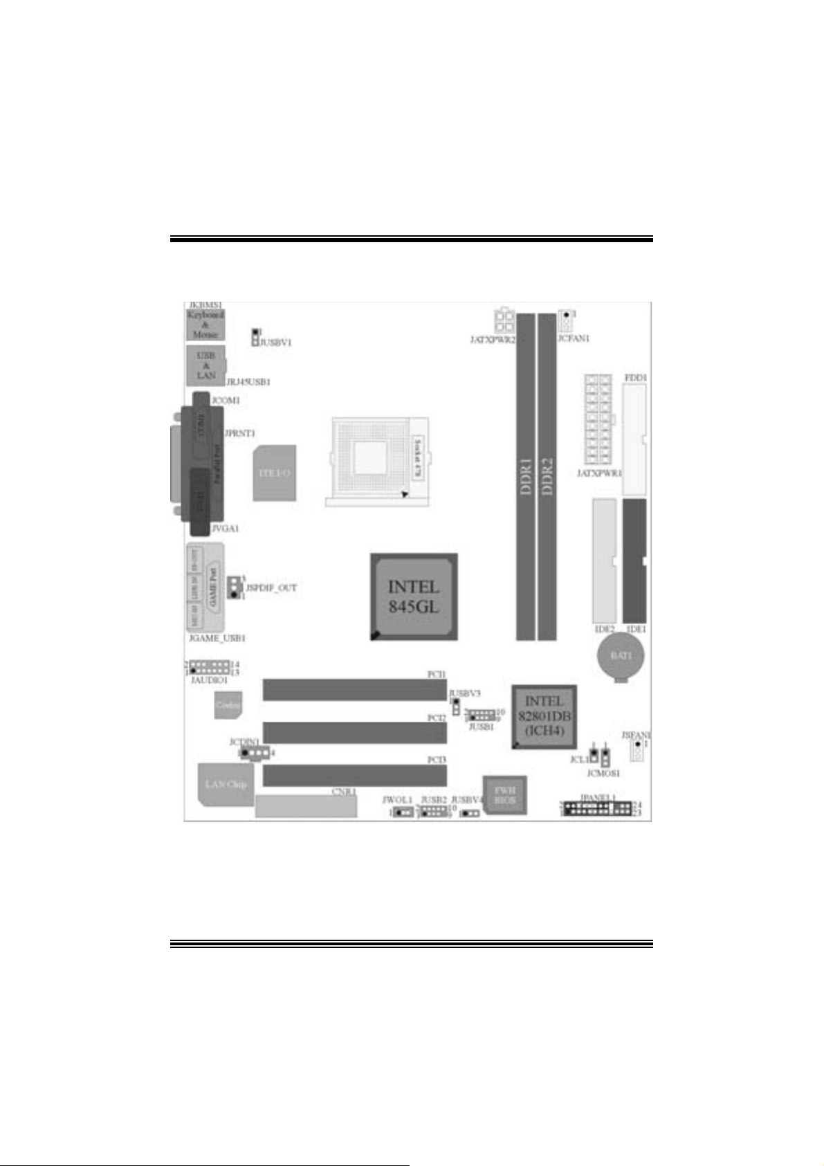
Layout of P4TD Q-V (only for ve r sion 1 .x)
※ NOTE: ●repres ents the first pin.
1
Page 4

Layout of P4TD Q-V (only for ve r s ion 7.x)
2
Page 5

English
1. P4TDQ-V Features
A. Har dware
CPU
Provides Socket 478.
Supports the Intel® Pentium® 4 proc essor.
Front Side Bus at 400/Fuzzy 533 MH z.
Chipset
Nort h Bridge: Intel 845GL
Sou t h B r i d ge: ICH4.
Main Me m o ry
Support s up t o 2 DDR devices.
Support s 200/ 266 MH z/ Fuzzy 333MHz (without ECC) dev ices
Maxi mu m memory s iz e o f 2GB.
Super I/O
Chip: ITE IT 8712F.
Low Pin Count I nterfac e.
Provides the most commonly us ed legacy Super I/ O funct ionality.
Env iro nm ent C ontrol initiatives
- H/W Monitor
- Fan Speed Controller
- I TE's "Smart Guardian" f unct ion
LAN (optional)
Chip: VIA VT6105.
Supports 10 Mb/s and 100 Mb/ s auto-negot iat ion.
Half / Full duplex capability.
Supports ACPI power management.
Slots
Three 32-bit s PCI bus master slots.
One C NR slot. (optional)
On Board IDE
Supports four IDE di s k dri ves.
Supports PIO Mode 4 and Ultra D MA 33/66/ 100 Bus Master Mode.
On Bo ard AC’97 Soun d Cod ec
Chip: C MI9739A
Compliant with AC ’97 s pec ific ation.
AC ’97 2. 2 int erface.
Support s 6 channels and S/PDIF-Out.
3
Page 6

On Board Peripherals
a. R e ar si de
1 s erial port .
1 VGA port.
1 gam e port.
1 parallel port. (SPP/EPP/ ECP mode)
1 audio port.
1 LAN port (optional).
PS/2 mouse and PS/2 keyboard.
2 USB2.0 ports.
b. F ront Si d e
1 floppy port supports 2 F DDs wit h 360K, 720K, 1.2M, 1.44M and 2. 88Mby t es.
1 S/PDIF-O ut Connector
1 CD -ROM Audio-In Connector
1 Front Aud io Conne c tor.
4 USB2.0 port s.
Dimensions
Micro ATX F orm Fac t or: 21.8 X 24.4c m. (W X L)
B. BIOS & Software
BIOS
Award legal Bios .
APM1.2.
ACPI.
USB Function.
Software
S uppor ts Warpspe ederTM, 9t h Tou c hTM, FLASHER™, WinFl asher
(optional).
Off ers the highest performance f or Windows NT, Windows 2000, Windows ME,
Windows XP, LINUX and UNIX series.
TM
and StudioFun!
TM
2. Pa ckage con tents
HDD Ca b le X1
FDD Cable X1
User’s Manual X1
Fully Setup Driver CD X1
St udioF un! Application C D X1 (opt ional)
USB Cable X1 (optional)
Rear I/ O Panel for Micro ATX Case X1 (opt ional)
4
Page 7
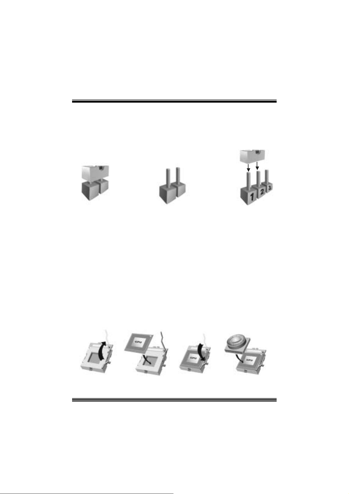
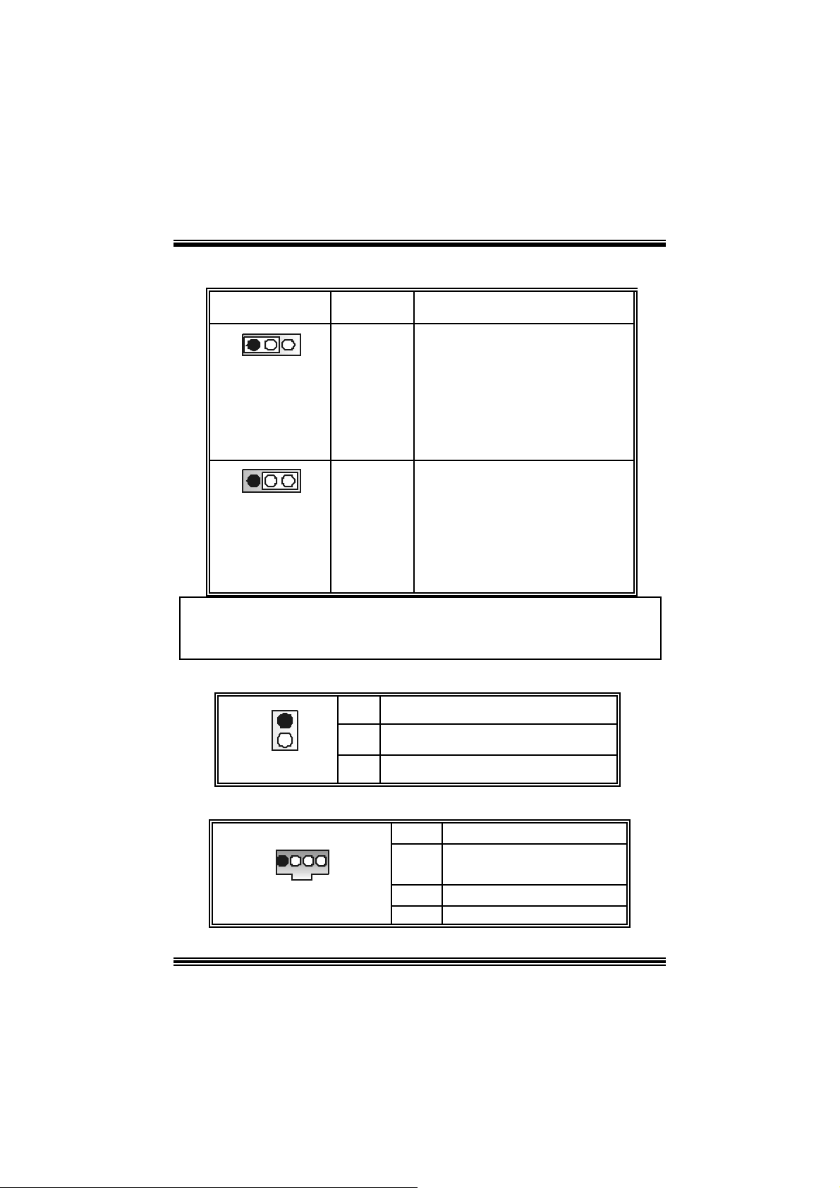
3. How to setup Jumper
The illustrat ion shows how jum pers ar e set up. W hen the Jumper c ap is place d on pins, t he
jumper is “close”. If no jumper cap is placed on the pins, the jumper is ”open”. The
illust rat ion sh ows a 3-pin jumper whos e pin 1and 2 are “close” when jumper c ap is placed
on thes e 2 pins .
Jumper close Jumper open Pin 1-2 close
4. CPU Ins t allation
Step1: Pull the lever sideways away from the soc k et and then raise the lever up to a
90 -degree angl e.
Step2: Look for the white dot/cut edge. The whit e dot/cut edge should point t owards the
lev er pivot. The C PU will fit only in the correct orient ation.
Step3: Hold the CPU down fir ml y, and then close the lever.
Step4: Put t he C PU f an on t he C PU and buck le it. C onnec t the C PU f an power cable to
the JCFAN1. This completes the installation.
Step1 Step2 Step3 Step4
5
Page 8

CPU Fan Headers: JCFAN1
1
3
JCFAN1
Pin No . A ssi gnme nt
1
2
3
FAN rpm Ra te Sense
Ground
+12V
S ystem Fan Headers: JSFAN1
1
3
JSFAN1
Pin No . A ssi gnme nt
1
2
3
FAN rpm Ra te Sense
Ground
+12V
5. DDR DI MM Modu les : DIMM1/ DIMM2
DRAM Access Time: 2.5V Unbu ffer ed DDR 200 /266/ Fuzz y 333 Type requ i red.
DRAM Type: 64MB/ 128MB/ 256MB/ 512MB/ 1GB DIMM Module (184 pin)
Total Memory Size wi th Un bu ffere d DIMM s
DIMM S ocket
Location
DIMM1 64MB/128MB/256MB/512MB/1GB
DIMM2 64MB/128MB/256MB/512MB/1GB
Installing DDR Module
1 . U nlo c k a DIM M sl ot by pres s ing the retai ning
cli p s outw a r d . A lign a DI MM to th e sl o t in the
way that the notch of the DIMM matches the
break of the slot.
2. Insert the DIMM firmly a nd verticall y into th e
slot unt il t he retaining clip snap back in place
and the DI MM is properly seated.
DDR Mod u l e To tal Memory
*1
*1
***On ly for refer en ce***
6
Size (MB)
Max is
2GB
Page 9
6. Jumpers, Headers, Conne ctors & Slots
(1) Floppy Disk Connector: FDD1
The mot herboard provides a standard f loppy disk connect or that supports 360K,
720K, 1.2M, 1.44M and 2.88M floppy disk types. This connector supports the
prov ided f loppy drive ribbon cables.
(2) Hard Dis k Connectors: IDE1/ IDE2
The motherboard has a 32-bit Enhanced PCI IDE Controller that provides PIO
Mode 0~4, Bus Mast er, and Ultra DMA 33/ 66/ 100 functionality. It has t wo HDD
connectors IDE1 (prim ary) and ID E2 (secondary).
The ID E c onnectors can c onnec t a mast er and a slav e drive, so you c an connect
up to four hard disk drives . The first hard drive should alway s be c onnect ed to
IDE1.
(3) Peripheral Component Interconnect Slo ts: PCI 1- 3
This m ot herboard is equipped wit h 3 standard PCI slots. PCI stands for Peripheral
Component I nterconnec t, and it is a bus standard f or expansion cards. This PCI
slot is designated as 32 bits.
(4 ) Commun ic ation Net w o rk R is er Slo t: CNR1 (op tiona l)
The CNR specification is an open I ndust ry St andard Architecture, and it defines a
ha rdw ar e scalable r iser card inter fa ce, which support s modem only.
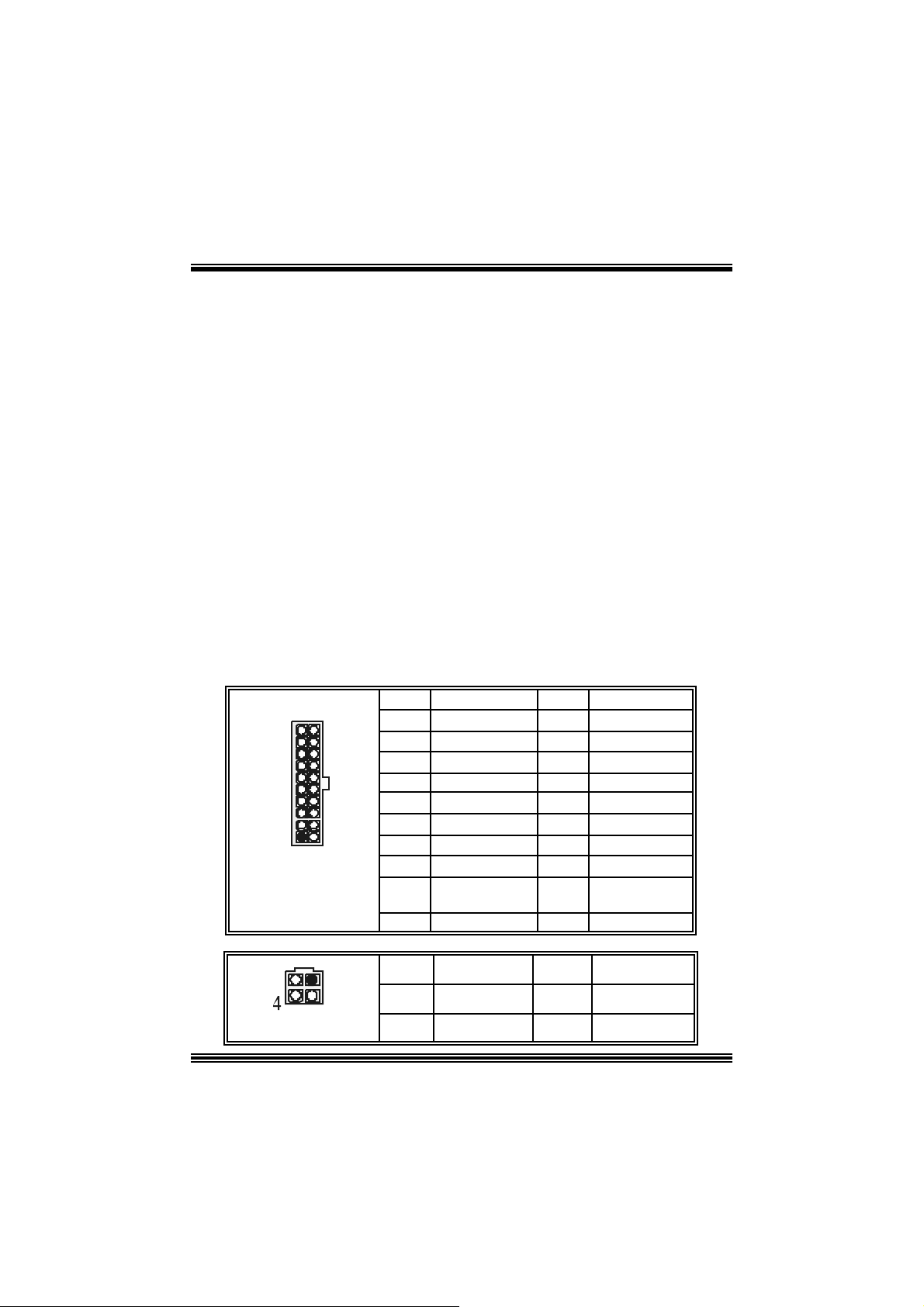
(5) Power C onnecto rs: JATXPWR1/JATXPWR2
PIN Assignment PIN Assignment
1 +3.3V 11 +3.3V
2 +3.3V 12 -12V
3 Ground 13 Ground
4 +5V 14 PS_ON
5 Ground 15 Ground
6 +5V 16 Ground
7 Ground 17 Ground
8 PW_OK 18 -5V
9 Standby Voltage
10 +12V 20 +5V
PIN Assignment PIN Assignment
1
2
+5V
+12V
+12V
19 +5V
3
4
Ground
Ground
10
1
JATXPWR1
JATXPWR2
20
11
12
3
7
Page 10
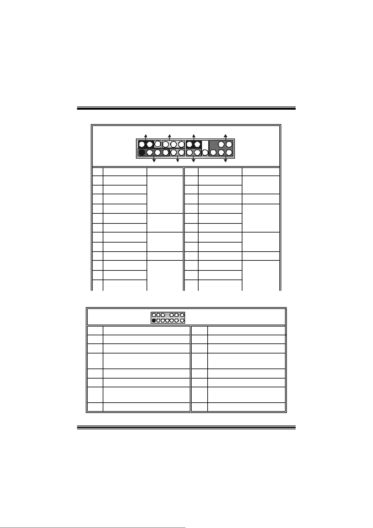
(6) Front Panel Connector: JPANEL1
SLP
JPANEL1
Pin Assignment Function Pin Assignment Function
1 +5V 2 Sleep C ont rol
3 NA 4 Ground
5 NA 6 NA NA
7 Speaker
9 HD D LED (+ ) 10 Power LED (+)
11 H DD LED (-)
13 Ground 14 Power Button
15 Reset Control
17 NA 18 KEY
19 NA 20 KEY
21 +5V 22 Ground
23 IRTX
2
123
PWR_LED
(+) (-)(+)
SPK
Speaker
Connector
Hard Dr ive
LED
Reset
Button
IrDA
Connector
(+) (-)
HLED
RST
8 Power LED (+)
12 Power LED (-)
16 Ground
24 IRR X
IRON/ OFF
IR
24
Sleep
Button
POWER
LED
Power-on
Button
IrDA
Connector
(7) Fro nt Panel Audio Header : JAUDIO1
2
1
Pin Assignment Pin Assign ment
1
3
Right L ine Out/ Spea ker Ou t Right
5
7
9 Left Line Out/ Speaker Out Left 10 Left Line Out/ Speaker Out Left
Right Line I n/ Rear Speaker R ight
11
Left Line I n/ Rear Speak er Left
13
Mic In/ C ent e r
Mic Power/ Bass
Reserv ed
14
13
JAUDIO1
2
4
6
8
12
Left Line In/ Rear Speaker Left
14
8
Ground
Audio Power
Right Line Out/ Speaker Out
Right
Key
Right Line I n/ R ear Speaker
Right
Page 11
(8) Power S ource Selecti on for USB: JUSBV1/ JUSBV3/ JUSB 4
JUSBV1/JUSBV3/
JUSBV4
Assignment Description
1 3
Pin 1-2 c lose
1 3
Pin 2-3 c lose
+5V JU SBV1: 5V for USB locat ed at the
JRJ45USB1 connector port
JU SBV3: 5V for USB locat ed at the
JUSB 1 connector port
JU SBV4: 5V for USB locat ed at the
JU S B 2 connector ports
+5V Standby
Voltage
JU SBV1: JRJ 45USB1 port powered
with s t andby volt age of 5V
JU SBV3: JUSB1 port powered with
standby v olt age of 5V
JU SBV4: JUSB2 port powered with
standb y voltage of 5V
Note: In o rder to support this function “Pow e r-on the system vi a USB device,
“JUSBV1/JUSBV3/JUSBV4” jumper cap should be placed on pin 2-3
respectivel y.
(9) Case Open Connector: JCL1 (optional)
1
JC1
Pin
1
2
Assign m ent
Case Open Signal
Ground
(10) CD-ROM Audio-In Header: JCDIN1
1 4
JCDIN1
Pin Assignment
1
2
3
4
9
Left Channel In put
Right Channel In put
Ground
Ground
Page 12
9
p
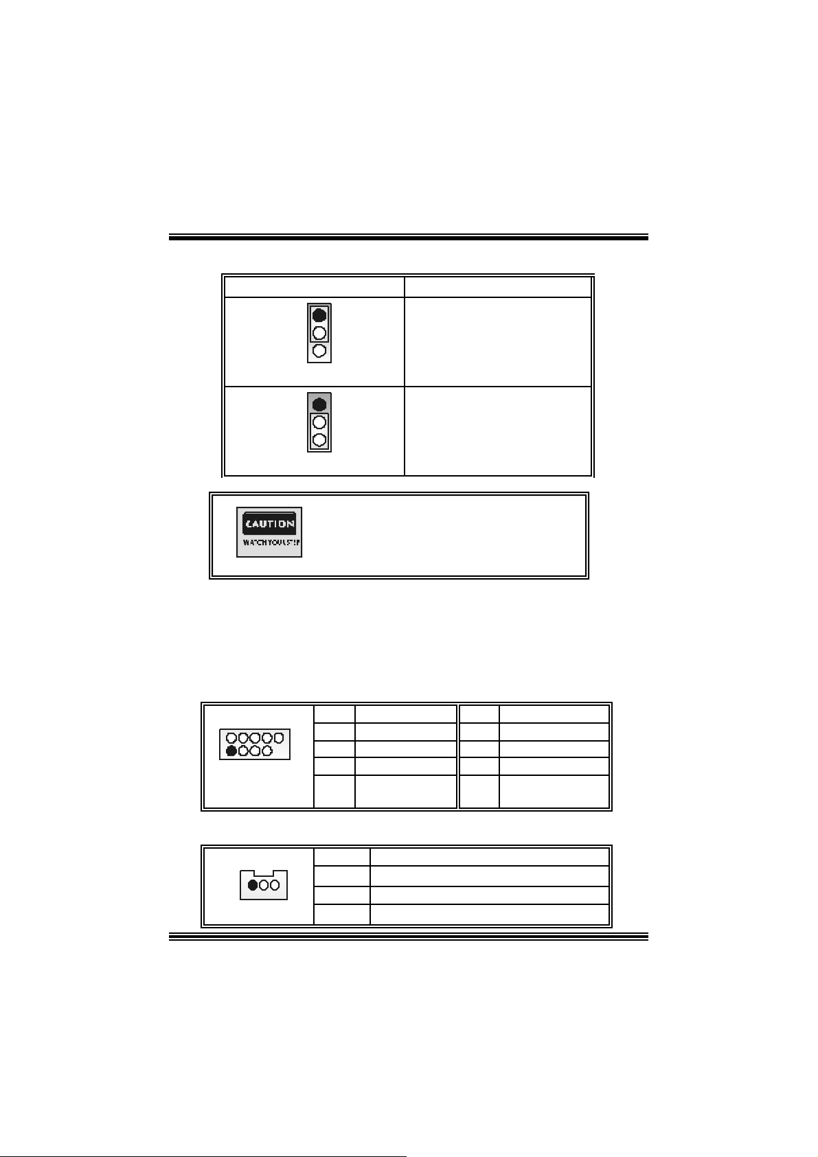
( 11) Clear CMOS Jumper: JCMOS1
JCMOS1 Assignment
1
3
Pin 1-2 C lose
1
3
Pin 2-3 C lose
Norm al Operation (def ault)
The following procedures are for resetting the
BIOS
assword. It is important to follow these
in st r u c ti ons c l osely .
※ Clear CMOS Procedures :
1. R emov e AC power line.
2. Set the jumper to “Pin 2-3 close”.
3. Wait for fi ve se conds.
4. Set the jumper to “Pin 1-2 close”.
5. Power on AC.
6. R eset y our des ired password or c lear the CMOS dat a.
(12) Front USB Header: JUSB1/2
2
1
JUSB1/2
Pin Assignment Pin Assignment
10
1
3
5
7
9
+5V
USBNUSBP+
Ground
KEY
(13) W ake On LAN Header : WO L1 (optional)
Pin Assignment
1 +5V Standby
2
3 Wake up
1
JWO L1
Clear CMOS Data
2
4
6
8
10
Ground
USBNUSBP+
Ground
+5 V
NA
10
Page 13
(14) Di gital Audio Connector: JSPDIF_OUT
Pin Assignment
1
1
JSPDIF_OUT
2
3
SPDIF_OUT
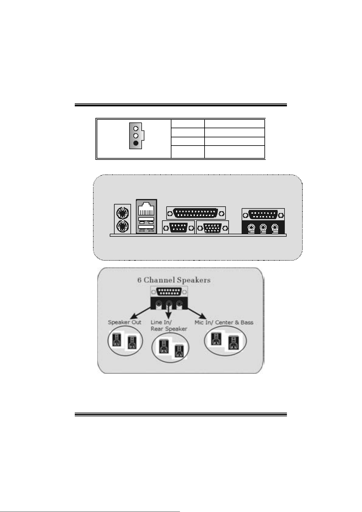
(15) Back Panel Connectors
+5V
Ground
JKBMS1
PS/2
Mouse
PS/2
Keyboard
JRJ45USB1
LAN(Optional)
USB
JPR NT1 JGAME_USB1
COM1
JCOM1
Parallel
VGA1
JVGA1
Game Port
Speaker
Out
Line In Mic
In
11
Page 14

StudioFun!TM
Introduction
StudioFun!TM is a media-player based on optimized GNU/Linux distribution to bring a
“Room Theater” experience into life. It plays DVD, VCD, MP3, Audio CD and other
mult im edia. F urt herm ore, Users c an t ake snapshots of video and c ust omize t he sav ed
images as screens avers or photo s lides hows. Of c ourse, the images can be s tored in U SB
mas s storage devic es like flash disks and US B floppy dis ks.
Hardw are Requirements
The supported hardware list of StudioFun! updates regularly. So please check the
“hwreq.txt” located in the root of StudioFun! Application Pack CD to get the latest
support ing inf ormat ion.
Ins tallation Proce dure
I ns e rt t h e “ St ud ioFu n! A ppl ic at io n Pack C D ” in a C D / DVD R O M dr iv e and l e t t h e sy s t em
boot through the CD . The dis k will boot and bring up the grub boot loader installation menu.
Two opt ions are specified: “St udioF un Install” and “St udioFun Rec over”.
12
Page 15

StudioFun! Install
This option will do the basic installation of the distribution. The installation works on
pre-inst alled windows or GNU / Linux dist ribution.
On select ing t he “St udioF un I nst all” option the installer boots and display s a dialog box
indicating the space required and waits for a conf irmation. Select ing “Ok” will co ntinue the
inst alla tion while selec t ing “Ca ncel” will t erminate t he inst allation and reboot the mach ine.
If Windows or GNU/Linux is the only OS ins talled on the hard disk wit h no f ree space, it
will resize the part ition, eit her NTFS or FAT32 or ext 2, and inst all StudioFun!. If t h e ha rd
disk has a 128MB of f ree space available, the inst allation w ill use t he free space.
Aft er installing the base system you will be prompted to select t he res olution from the
following choice s
1. 1024x768 (rec omm ended)
2. 800x 600
3. 640x 480
Select the desired resolut ion. The def ault is 1024x 768 f or high-end graphics.
Nex t y ou will be prom pted t o c hoose t he D VD area/region s elec tion code. Choose t his
bas ed on the type of D VDs y o u will be playing .
The installation procedure will then probe for the type of mouse installed. The distribution
currently s upports PS/2, USB and Serial m ice. In case of serial m ouse you will hav e t o
mov e the mouse when prompted. The other two are probed and installed autom atic ally .
The installation procedure will now finish, the CD is eje c ted and a dialog box prompting to
reboot t he m achine is dis play ed. Press “OK” but t on and enjoy StudioF un!.
3.1.1 Error Messages
1. M edia corrupted!! Please check t he m edia! The CD-R OM is corrupt ed.
2. Extraction of base system failed!!
3.Unsupported hardware found, Aborting...
unsupported and undocumented hardware the above error m ess age is popped.
4. No device f ound!
This error m es sage is giv en if there is no hard disk in the system.
Please t ry again later!! The CD-ROM is corrupted.
If you try to install StudioFun! on an
13
Page 16

StudioFun! Recove r
Where there is a MBR (Master Boot record) corruption, the “StudioFun Recover” will
autom atic ally probe t he hard disk mast er boot record and find out the installed operating
sy ste m (s). O nc e suc c ess, it will re-ins t all the b oot lo ader with correct o ptions in the MBR.
Please be noted that the newly probed one will over write any custom boot loader option
spec if ied from other GNU/Linux installations .
B o oting to S t udi o F un!
Aft er the Ins t allat ion, rem ove the CD f rom the CD -ROM and res t art the system. Aft er t he
rebooting, you will get t he “GRU B boot loader menu screen”. Select the StudioF un! Option
to boot to the StudioFun! Part it ion.
Aft er execut ing the boot up, you will see t he main Desktop sc reen. The following sect ion is
a com plete descript ion of t he D eskt op application.
14
Page 17

Desktop
This is the main shell of the St udioFun! software. It illust rat es two m ain categories, one is
the m ain "Media Control
" part and the other is t he "C ontrol Panel".
Media control
The Med ia Control consists of the fo llowing fu nctionalities:
1. VCD
This co ntrol ic on will glow whenever a VC D is det ected in a DVD/CD-R OM driv e. The VC D
will be aut o-play ed only when it is put in to the driv e when the Desktop (StudioFun! shell)
is up and running whereas the control will simply glow to inform the user about a VCD
present in t he DVD/CD-ROM drive when the D esktop is not launched.
2. DVD
This control will glow whenever a DVD is detected in a DVD drive. The DVD will be
auto-played only when it is put in to the drive when the D esk top (StudioFun! s hell) is up
15
Page 18

and running, otherwise, the control will simply glow to inform the user about a DVD
present in t he DVD/CD-ROM.
3. MP3
This c ontrol will glow whenever a MP3 is detect ed in a DVD/CD-R OM drive. The MP3 will
be auto-play ed only when it is put in to t he driv e when the Desktop (StudioFun! shell) is up
and running, otherwise, the control will simply glow to inform the user about a MP3
present in t he DVD/CD-ROM drive.
4. AU DIO
This control will glow whenever a AUDIO is det ected in a D VD /CD-R OM driv e. The AUDI O
will be aut o-play ed only when it is put in to the drive when the Des ktop (StudioF un! shell)
is up and running, ot herwise, the control will simpl y glo w to inf orm the user about a A UDI O
present in t he DVD/CD-ROM drive.
5. FILE
This co ntrol will glow whenev er a File C D (CDs with other m edia type f iles) is det ect ed in a
DVD/CD-ROM drive. The F ile CD will be auto-play ed only w hen it is put in t o th e dr iv e
when the Des kt op (StudioFun! s hell) is up and running, otherwise, the control will s imply
glow to inf orm t he user about a File CD pres ent in the D VD/CD -R OM drive.
6. EJECT MEDIA
When c lick ed this c ontrol, the file dis k fro m the DVD/CDROM driv es will be ejec t ed.
7. EXIT
This is the "Power on/ off" control of the D esktop (StudioFun! shell).
Co nt ro l Pa nel
The Cont rol panel part has five ic ons, which are shortcut s to other applications pres ent in
the St udioFun!. Tool tips will pop up once the mouse is rolled t o the icons
1. Select Region
Click ing t his icon will inv oke t he application f or s e lect ion D VD region sett ings. Refer t o
sec t ion 5. 2 Select DVD Region applicat ion f or more details.
2. Screensaver
Clicking this icon will invoke the screensav er application. Refer to section 5.3
Screensaver f or more details.
16
Page 19

3. Display Settings
Clicking this ic on will inv oke the applicat ion for c hanging the screen resolutions. R efer to
se cti on 5.4, D i sp l a y Se ttin g s f or more details.
4. File Manager
Clicking thi s icon will invoke the file manager. Re fer to section 5 .6 File manager fo r m o r e
details .
When u ser h as a D VD an d a C D -R OM D r i ve, DV D Drive ha s th e p rio rity :
If user has both DVD and a CD -R OM drive, DV D driv e will be given t he pref erence when
both the drives hold valid media in them, i.e., if the CD -ROM driv e has a media and a DVD
drive als o has a me dia, a nd the StudioFun! is st arted, t he disk ins ide the DVD drive will be
played.
Other general user scenarios
When a us er clicks on any of t he media-controls when it is not glowing, ex cept the eject
media and exit, the media-player will just c ome up and wait f or user input.
S oftware Details
XIN E
XI N E is a multim edia play er. It play s bac k Audio CD, DVD, and VCD. It also decodes
mult imedia files like AVI, MOV, WMV, and MP3 from loc al disk drives. It interpret s m ost of
the c ommon multim edia form ats.
17
Page 20

• Features of Xi ne
a. Skinnable GUI
b. Navigation controls (seeking, pause, fast, slow, next
chapter, etc)
c. On Screen Display (OSD) features
d. DVD and external subtitles
e. DVD/VCD menus (requires external plug-in)
f. A udio and s ubtitle channel selection
g. Closed Caption su ppo r t
h. Bright ness, cont rast, audio volume, hue, saturation
adjusting requires hardware/driver support)
i. Playlist
j. Image snapshot
k. Audio re-sampling
l. Software de-interlacing algorithms
m. Configuration dialog
n. Aspect ratio changing
o. Full- screen display
• Supported File Formats
a. Video CD
b. MPEG program streams (.mpg, .mpeg)
c. ogg (.ogg) avi (.avi)
d. asf (.asf, .wmv)
e. QuickTime (.mov)
f. MPEG-Video (.mpv, .m2v)
g. MPEG-Audio (.mp2, .mp3)
h. WAV (.wav) Video CODEC
i. MPEG 1/2
j. MPEG 4 (aka OpenDivX)
k. MS MPEG 4
a. C hapter 5: Softw are Det ails 10
l. Windows Media Video 7
m. Motion JPEG
• Remote Contr ol Suppo rt .
a. Inf rared interface
18
Page 21

b. Us er-friendly
• Usage of S tudioFun! with CelomaChro me skin
a. Select VCD button to play a VCD disc
b. Select DVD button to play a DVD disc
c. Select CDDA butt on to play a Audio CD
d. Select next chapter or MRL (>>|) button to play next track
in Audio CD, VCD and MP3 songs and to play next
chapter in DVD
e. Select prev ious chapter or MRL (|<<) button to play
previous t rack in Audio CD, VCD and MP3 songs and to
play previous chapter in DVD
f. Sel ect slow mot ion (<<) butt on to play the video / audio in
slow motion (Select play button after reaching the r equired
position)
g. Select fast motion (>>) button to play the video / audio in
fast mot ion ( Select play button after reaching the required
position)
h. Select subs + / - button to select the app ropriate subtitle
(Usable while p laying
i. Select audio + / - button to select the appr opriat e audio
track (For example when
j. The DVD contains one audio track in English and the
other wit h some ot her language,
k. Us a ble while playing DVD’s )
l. Select “hide button” t o hide the control panel of the player
m. Select “menu” button t o use menu while playing DVD
n. Select “control” button to adjust brightness / color
o. Select “setup” button to modify the settings of the player
p. Select ”f.scr” button to show the video output of the player
in full screen mode
q. Select “snap” button to take a snapshot of the currently
playing video
r. Select “plist ” button to add / remove / manage playlist
s. Select “mrl” button to add new file to play
19
Page 22

Select Region
Overview
Select region is a utility to set a DV D region. W ith the help of t his applicat ion user can s et
or change a DVD region. Only one region c an be set at a t ime.
About Select Region
Wit h the help of t his applic ation y ou can set a region for DVD. Only one region c an be set
at a time. If y ou keep the mous e pointer on any region, y ou can v iew t he count ries, whic h
comes u nder that region.
“Ok ” - Click to set the selected region.
“Canc el” - C lick to quit the application.
How to select DVD region
You can selec t only one region at a time. You can change your selec tion by clicki ng on
any ot her region.
• A snapshot of the application is shown below:
Screensaver
Screensaver
The xscreens aver daemon waits until the keyboard and mous e hav e been idle for a period,
and then runs a graphics dem o c hosen at random. The demo is t erm inated as soon as
there is any m ouse or key board act ivity.
20
Page 23

The xscreensav er-demo program is the graphical user interface to xscreensaver. It lets
you t une the v arious paramet ers used by t he xscreensav er daemon, and browse t hrough
the graphics dem os.
StudioF un! com es with xscreens aver when you click on the screensav er ic on the
applicat ion com es up. Then user c an choos e v arious graphics dem os like
chbg, halo,hypercube or hyperball.
Screensa ver comes with various options
• Preview Option: When a user s elects a particular graphic s demo and c lick s on preview
button the demo come s up.
• Blank After Option: The screens aver will blank the screen aft er the keyboard and mous e
have been idle default tim e is 1minute and user c an change the settings.
• Cycle After Option: When screensav er is running this cycle time defines the time limit for
each screensav er.
• Mode Screens aver com es with various modes:
1. R andom Screen Saver: When user choos es t his option, Screens av er cycles through
various graphic s dem os randomly
2. Only one Screen Saver: W hen user choos es t his option, screens aver displays only one
graphics dem o.
3. Blank S creen O nly: When user choose s thi s option, s creensaver only blanks the screen
inst ead of dis playing t he graphics demo.
4. D isable Screen Saver: When user chooses this option, screens aver is disabled.
• Various Graphics Dem os
XSc reensaver comes with various screens aver
Chbg: This screens aver displays the images stored in StudioFun! the time gap between
images is 5 sec onds.
Hyperball
Hyperc ube
Halo
Strange
• A snapshot of the application is shown below:
21
Page 24

Display Settings
Display Settings
Displa y setting is a progra m to change the current resolu tion se t tings o f the Display.
By def ault user of St udioF un! will be given a choice to select bet ween any of the following
three resolut ions.
• 640x480
• 800x600
• 1024x768
The current resolut ion of t he Display will be selected by def ault. It requires restart of t he
StudioF un! to ref lect the c hanges made.
File Manage r
Overview
File manger i s a ut ilit y to copy files from defer ent de vices to hard di sk and vice versa . User
can c opy files f rom devices such as, f loppy , CD -Rom and F las hdis k to hard dis k and also
from hard disk to floppy and Flas hdisk.
22
Page 25

About File manager
The hard disk files are stored in a direct ory c alled “/ studiof un” on t he hard disk. You c an
also delete files from hard disk, bu t you cannot delete files from any de vi ce.
Selec t dev ice - Contains the device names /floppy, /cdrom and /flashdisk. Select a
device fro m /to which you want to copy fi les .
twice to mount the device.
List Directories - Shows the list of directories of the selected device aft er double
click in g it.
Floppy/cdrom/ F lashdisk - Shows the cont ents of the selected direc tory from the “Lis t
direc t ories“ field after double clic k ing it.
Hard disk - Shows the contents of a directory c alled “/ studiof un”.
Add (>>) - Click to copy selected files from a device to hard disk.
Add (<<) - Click to copy selected files from hard disk to a dev ice.
Remove - C l i ck to delete fi l e s from ha r d di sk.
Exit - Click to quit the application.
P l ease do u b l e cl ic k th e d evice o p ti o n
23
Page 26

WarpSpeeder
Introduction
[ W arpSpeeder™ ], a new powerful control utility, features three user-f riendly functions
including Ov erclock Manager, Ov ervolt age Manager, and Hardware Monit or.
With the Over clock Manager, users can easil y adjus t th e freque nc y they prefer or they can
get t he best CPU performance wit h jus t one click. The Overv oltage Manager, on the other
hand, helps to power up CPU core voltage and Memory voltage. The cool Hardware
Monitor smartly indicates the tem peratures, voltage and CPU fan s peed as well as the
chips et inf ormat ion. Als o, in the About panel, y ou c an get det ail des c riptions about BI OS
model and chipsets. In addition, the f requency status of C PU, m emory, AGP and PCI
along with t he CPU s peed are synchronically shown on our main panel.
Moreov er, to prot ect users' com puter sy s t ems if t he sett ing is not appropriate when testing
and results in system f ail or hang, [ WarpSpeeder™ ] technology assures the system
st ability by automat ica lly rebooting the com puter and then restart t o a speed that is either
the original sys t em s peed or a suit able one.
System Requirement
OS Support : Windows 98 SE, W indows Me, Windows 2000, Windows XP
Direc t X: DirectX 8.1 or above. (The Windows XP operating sy s tem inc ludes D irectX 8. 1. If
you us e Windows XP, y ou do not need to inst all DirectX 8.1. )
24
Page 27

Installation
1. Execut e the setup ex ecution f ile, and then the f ollowing dialog will pop up.
Please clic k “Next” butt on and follow t he default proc edure t o install.
2. When you see the following dialog in setup procedure, it means setup is
comple ted . If th e “Launch the War pSpeeder Tray Ut ility” checkbox is checked,
the Tray Icon utility and [WarpSpeeder™] utility will be automatically and
imm ediately launched after you c lic k “Finish” butt on.
25
Page 28

Usage
The foll o wi ng fi gu r es ar e ju st on ly for re f er e nce , t h e s c reen pr inted in th is u s er ma nual w ill
change according to your motherboard on hand.
[W arpSpeeder™] includes 1 t ray ic on and 5 panels:
1. Tray Icon:
Whenev er the Tray Icon ut ility is launched, it will disp lay a little tray icon on the right side of
Windows Tas k bar.
26
Page 29

This utility is responsible f or convenient ly inv oking [WarpSpeeder™] U tility. You can use
the m ouse by clicking t he lef t button in order t o inv oke [W arpSpeeder™] direct ly from the
litt le t ray icon or you can right-c lick t he litt le t ray icon t o pop up a popup menu as following
figure. The “Launch Utility” item in the popup menu has the sam e function as mouse
left -c lick on tray icon and “Exit” item will c los e Tray I c on utility if select ed.
2. Main Panel
If you click the tra y icon, [ WarpSpeeder™ ] utility will be invoke d. Please refer
do the following figure; the u tility’s first window you will see is Main Panel.
Main Panel contains features as follows:
a. Display t he CPU Speed, CPU external c lock, Memory clock, AGP clock, and PC I
cloc k inform at ion.
b. Contains About, Voltage, Overclock, and Hardware Monitor Buttons for invoking
respective panels.
c. With a user-friendly Status Animation, it can represent 3 overclock percentage
stages:
Duck walk ing => overc lock perc entage from 100% ~ 110 %
Duck running => overcloc k perc ent age from 110% ~ 120%
Duck burning => overcloc k perc ent age from 120% ~ abov e
27
Page 30

3. Voltage Panel
Click t he Volt age button in Main Panel, t he but ton will be highlighted and the Volt age
Panel will slide out t o up as the f ollowing f igure.
In this panel, y ou c an decide t o increase CPU c ore v oltage and Memory v oltage or not.
The def ault sett ing is “N o”. If y ou want to get the best perf ormance of ov erclocking, we
r ec ommen d y ou c lic k th e opti on “Y es”.
28
Page 31

4. Overclock Panel
Click t he Overc lock button in Main Panel, the butto n will be high light ed and the Overc lock
Panel will slide out t o left as the following figure.
29
Page 32

Overclock Panel contains these features:
a. “–3MHz button”, “-1MHz but t on”, “+1MHz butt on”, and “+3MHz button”: provide user
the a bility t o do real-t im e ov e rc lock a djustment .
Warning: Manually overclock is potentially dangerous, especially when the
overclocki ng percentage is over 110 %. We strongl y recommend you verify
every speed you overclock by click the Verify button. Or, you can just click
Auto overclock button and l et [ WarpSpeeder™ ] automatically gets the best
result for you.
b. “R ecovery Dialog button”: Pop up the following dialog. Let user select a restoring
way if sy s tem need t o do a f ail-s afe reboot.
30
Page 33

c. “Aut o-ov erclock button”: Us er can c lick this button and [ WarpSpeeder™ ] will set
the best and stable perform ance and frequency automatic ally . [ WarpSpeeder™ ]
utility will ex ec ute a se ries of test ing until syst em fail. Then sys t em will do f a il-s afe
reboot by us ing Watc hdog f unct ion. Aft er reboot, the [ WarpSpeeder™ ] utility will
restore to the hardware default setting or load the verified best and stable
frequency a c cording to the Recovery Dialog’s setting.
d. “Verify button”: User can c lick this button and [ W arpSpeeder™ ] will proceed a
testing for current frequenc y. If the tes ting is ok, t hen the c urrent f requen cy will be
sav ed into sy st em registry . If the testing f ail, syst em will do a fail-safe rebooting.
After reboot, the [ WarpSpeeder™ ] utility will restore to the hardware default
setting or load the verif ied best and stable frequency acc ording to t he Recov ery
Dialog’ s se tting.
Note: Because th e testing programs, in voked in A u to-overclock and Verify,
include DirectD raw, Direc t3D and Dir ect Show tes ts, the DirectX 8. 1 or newer
runtime l ibrary is required. And please make sure your display card’ s color
depth is High color (16 bit) or True color( 24/32 bit ) that is required for
Direct3D rendering.
31
Page 34

5. H ardware Monit or Panel
Click the H ardware Monitor button in Main Panel, the butt on will be highlighted and the
Hardware Monitor panel will s lide out to left as the following f igure.
In t his panel, you c an get the real-time stat us inform ation of y our system. The inf ormat ion
will be ref res hed ev ery 1 s econd.
6. About Panel
Click the About button in Main Panel, the butt on will be highlighted and the About Panel
will slide out t o up as t h e following figu re.
In t his panel, you can get model name and detail inf ormat ion in hints of all t he chips et that
are related to overclocking. You can also get the mainboard’s BIOS model and the
Version number of [ WarpSpeeder™ ] utility.
32
Page 35

Note: Because the overclock, overvol tage, and hardware monitor features
are controlled by several separate chipset, [ WarpSpeeder™ ] divide these
features to separate panels. If one chipset is not on board, the correlative
button i n Main panel will be disabled, but will not interfere other panels’
functions. Thi s property can make [ WarpSpeeder™ ] utility more robust.
33
Page 36

Trouble Shooting
g
e
e
r
y
plugg
e
g up
y
pp
a
prog
e
r
e
n
o
o
PROBABLE SOLUTION
No pow er to the system at all; power light does n’t
illuminate; fan inside power supply does not turn
on. Indicator li
System inoperative. Keyboard lights are on,
power indic ator lights are lit, and hard dri ve i s
sp in ning.
System does not boot from hard disk drive, but it
can be booted from CD-ROM drive.
System only boots from CD-ROM. Hard disk can
be read and applications can be used but
booting from hard dis k is i mpossible.
ht on keyboard does not turn on.
PROBABLE SOLUTION
PROBABLE SOLUTION
PROBABLE SOLUTION
* Make sure power cable is securely plugged in.
* Repl ac e c abl e.
* Contact tec hnic al s upport.
* Using even pressure on both ends of th
DIM M, press down firmly until the modul
snaps back in places.
* Check cable running from disk to dis k controlle
board. Make sure both ends are securel
ed in; check the drive type in th
standard CMOS setup.
* Backin
important. All hard disks are capable o
breaking down at any time.
* Bac k up data and applications files. Reforma
the hard drive. Re-i nstall a
using backup disks.
the hard drive is extremel
l icat ions and dat
PROBABLE SOLUTION
Screen m essage says “Invalid Confi guration” or
“CMOS Failure.”
* Review system’s equipment. Make sure correc
in formation is in setup.
PROBABLE SOLUTION
Cannot boot system after installi ng sec ond hard
drive.
* Set master/slave jum p e rs c o rrectly.
* Run SETUP
types. Call drive manufacturers fo
compatibility wi th other dri ves.
ram and select correct driv
PROBABLE SOLUTION
E rror message reading “SECTOR NOT FOUND”
or other error messages not allowing certai n data
to be retrieved.
* Back up any salvageable data. Then, low-leve
format, partition, and high-level format th
hard drive. Re-install all saved data whe
completed.
PROBABLE SOLUTION
Scree is blank. * Check the power connectors to monitor and t
syst em . Make s ure m onitor is co nnec te d t
display card.
34
Page 37

e
n
n
o
PROBABLE SOLUTION
Screen goes blank periodically. * Disable screen saver.
PROBABLE SOLUTION
Mem ory problem. * Reboot computer. Reinstall memory, and mak
sure that al l memory modules are install ed i
correct sockets.
PROBABLE SOLUTION
Computer virus. * Use anti-virus programs to detect and clea
viruses.
PROBABLE SOLUTION
Keyboard failure. * Reconnect keyborad. Check keys again. If n
improvement, replace keyboard.
PROBABLE SOLUTION
No display on screen. * If possible, connect monitor to another system
If no c olor still, replace monitor.
PROBABLE SOLUTION
C: drive fail ure. * Check hard drive cable.
PROBABLE SOLUTION
Missing operating system on hard drive. * Run setup and sel ect correct drive type.
PROBABLE SOLUTION
Certain keys do not function. * Replace keyboard.
PROBABLE SOLUTION
Keyboard is locked, no keys function. * Unlock keyboard.
35
Page 38

12/18/2003
36
Page 39

P4TDQ-V BIOS Setup
BIOS Setup........................................................................................1
1 Main Menu.....................................................................................................3
2 Standard CMOS Features .............................................................................. 6
3 Advanced BIOS Features...............................................................................9
4 Advanced Chipset Features..........................................................................12
5 Integrated Peripherals ..................................................................................15
6 Power Management Setup ........................................................................... 19
7 PnP/PCI Configurations............................................................................... 24
8 PC Health Status ..........................................................................................26
9 Frequency Control ....................................................................................... 27
i
Page 40

P4TDQ-V BIOS Setup
BIOS Setup
Introduction
T his manua l disc ussed Award™ Setup p rogram bu ilt in to the ROM BIOS. T he Setup
program allows users to modify the basic system configuration. T his special information is
th en st ored in ba tte ry-b acke d RAM so that it r etain s the Set up info rmatio n when the power
is turned off.
T he Award B IO S™ insta lled in you r com puter system’s RO M (R ead Only Me mory ) is a
custom version of an industry standard BIOS. This means that it supports Intel Pentium
processor input/output system. The BIOS provides critical low-level support for standard
devices such as disk drives and serial and parallel ports.
Addin g important has customized the Award BIOS™, but nonstandard, features such as
virus and password protection as well as special support for detailed f ine-tuning of the
chipset controlling the entire system.
The rest of this manual is intended to guide you through the process of configuring your
system using Setup.
Plug a nd Play Support
These AWARD BIOS supports the Plug and Play Version 1.0A specification. ESCD
(Extended System Configuration Data) write is supported.
EPA Green PC Support
This AWARD BIOS supports Version 1.03 of the EPA Green PC specification.
APM Support
These AWARD BIOS supports Version 1.1&1.2 of the Advanced Power Management
(APM) specification. Power management features are implemented via the System
Management Interrupt (SMI). Sleep and Suspend power mana gement modes are supported.
Power to the hard disk drives and video monitors can be managed by this AW ARD BIOS.
®
4
1
Page 41

P4TDQ-V BIOS Setup
PCI Bus Suppo rt
This AW ARD BIOS also supports Version 2.1 of the Intel PCI (Peripheral Component
Interconnect) local bus specificat ion.
DRAM Support
DDR SDRAM (Double Data Rate Synchronous DRAM) are supported.
Suppo rted CP Us
This AWARD BIOS supports the Intel Pentium
Us i ng Se t u p
In general, you use the arrow keys to highlight items, press <Enter> to select, use the
<PgUp> and <PgDn> keys to change entries, press <F1> for help and press <Esc> to quit.
The following tab le provides more detail about how to navigate in the Setup program by
using the keyboard.
Keystroke Function
Up arrow Move to p revio us i tem
Down arrow Move to next item
Left arro w Move to the item o n the left (men u bar)
Right arrow Move to the item o n the right (menu bar)
Move Enter Move to the item you desired
PgUp key Increase the numeric value or make changes
PgDn key Decrease the numeric value or make changes
+ Key Increase the numeric value or make changes
- Key Decrease the numeric value or make changes
Esc key Main Menu – Quit and not save changes into CMOS
F1 k ey Genera l help o n S etup navig ation k eys
F5 key Load previous values from CMOS
F7 key Load the optimized defaults
F10 key Save all the CMOS changes a nd exit
®
4 CPU.
Status Page Setup Menu and Optio n Page Setup Me nu – Exit
Current page and return to Main Menu
2
Page 42

P4TDQ-V BIOS Setup
1 Main Menu
Once you enter Award BIOS™ CMOS Setup Utility, the Main Menu will appear on the
screen. The Main Menu allows you to select from several setup functions. Use the arrow
keys to select among the items and press <Enter> to accept and enter the sub-menu.
!! WARNING !!
The information about BIOS defaults on manual (Figu re
1,2,3,4,5,6,7,8,9) is just for reference, please refer to the BIOS
installed on board, for update information.
Figure 1. Main Menu
Standard CM OS Features
This submenu contains industry standard configurable options.
Advance d BIOS Features
This submenu allows you to configure enhanced features of the BIOS.
Advanced Chipset Features
This submenu allows you to configure special chipset features.
Integrated Peripherals
This submenu allows you to configure certain IDE hard drive options and Programmed
Input/ Output features.
3
Page 43

P4TDQ-V BIOS Setup
Power Management Setup
This submenu allows you to configure the power management features.
PnP/PCI Configurations
This submenu allows you to configure certain “Plug and Play” and PCI options.
PC Health Status
This submenu allows you to monitor the hardware of your system.
Fre que ncy Contro l
This submenu allows you to change CPU Vcore Voltage and CPU/PCI clock. ( Howev er,
this function is strongly recommended not to use. Not properly change the
voltage and clock may cause CPU or M/B damage!)
Lo a d Op ti mize d De fa ul ts
This selection allows you to reload the BIOS when the system is having problems
particularly w ith the boot sequence. These configurations are factory settings optimized
for this system. A confirmation message will be displayed before defaults are set.
Set Supervisor Password
Setting the supervisor password will prohibit everyone except the supervisor from making
changes using the CMOS Setup Utility. You will be prompted with to enter a password.
4
Page 44

P4TDQ-V BIOS Setup
Set User Password
If the Supervisor Password is not set, then the User P assword will function in the same way
as the Supe rvisor P asswor d. If th e Supervis or Pas swor d is set and the User Pa ssword is
set, the “User” will only be able to view configurat ions but will not be able to change them.
Save & Exit Setup
Exit Without Saving
Upgrade BIOS
Save all configuration changes to CMOS(memory) and exit setup. Confirmation message
will be displayed before proceedin g.
Abandon all changes made during the current session and exit setup. confirmation
message will be displayed before proceeding.
This submenu allows you to upgrade bios.
5
Page 45

P4TDQ-V BIOS Setup
2 Standard CMOS Features
The items in Standard CMOS Setup Menu are divided into 10 categories. Each category
includes no, one or more than one setup items. Use the arrow keys to highlight the item and
then use the<PgUp> or <PgDn> keys to select the value you want in each item.
Figure 2. Standard CMOS Setup
6
Page 46

P4TDQ-V BIOS Setup
Main Menu Selec tions
This table shows the selections that you can make on the Main Menu.
Item Options Description
Date mm : dd : yy Set the system date. Note
Time hh : mm : ss Set the system internal
IDE Primary Master Options are in its sub
menu.
IDE Primary Slave Options are in its sub
menu.
IDE Secondary Master Options are in its sub
menu.
IDE Secondary Slave Options are in its sub
menu.
Drive A
Drive B
Video EGA/VG A
360K, 5.25 in
1.2M, 5.25 in
720K, 3.5 in
1.44M, 3.5 in
2.88M, 3.5 in
None
CGA 40
CGA 80
MONO
that the ‘Day’ automatically
changes when you set the
date.
clock.
Press <Enter> to enter the
sub menu of detailed
options
Press <Enter> to enter the
sub menu of detailed
options.
Press <Enter> to enter the
sub menu of detailed
options.
Press <Enter> to enter the
sub menu of detailed
options.
Selec t the type of floppy
disk drive installed in your
system.
Select the default video
device.
7
Page 47

P4TDQ-V BIOS Setup
Item Options Description
Halt On All Errors
No Errors
All, but Keyboard
All, but Diskette
All, but Disk/ Key
Base Memory N/A Displays the amount of
Extended Memory N/A Displays the amount of
Total Memory N/A Displays the total memory
Select the situation in which
you want th e BIOS to st op
the POST process and
notify you.
conventional memory
detected during boot up.
extended memory detected
during boot up.
available in the system.
8
Page 48

P4TDQ-V BIOS Setup
3 Advanced BIOS Features
Figure 3. Adva nce d BIOS Se tup
Virus Warning
T his op tion allows yo u to choo se the Viru s Warnin g feature t hat is used to prote ct the I DE
Hard Disk boot sector. If this function is enabled and an attempt is made to write to the
boot sector, BIOS will disp lay a warning message on the screen and sound an alarm beep.
Quick Power On Self Test
Enabling this option will cause an abridged version of the Power On Self-Test (POST) to
execute after you power up the computer.
Boot Up NumLock Status
Selects the NumLock. State after power on.
Gate A20 Option
Select if chipset or keyboard controller shou ld control Gate A20.
Disabled (default) Virus protection is disabled.
Enabled Virus protection is activated.
Enabled (default) Enable quick POST.
Disabled Normal POST.
On (default) Numpad is number keys.
Off Numpad is arrow keys.
9
Page 49

P4TDQ-V BIOS Setup
Normal A pin in the keyboard controller
controls Gate A20.
Fast (default) Lets chipset control Gate A20.
Typematic Rate Setting
When a key is held down, the keystroke will repeat at a rate determined by the keyboard
controller. When enabled, the typematic rate and typematic delay can be configured.
Disabled (default)
Enabled
Typematic Rate (Chars/Sec)
Sets the rate at which a keystroke is repeated when you hold the key down.
The Choices: 6 (default), 8,10,12,15,20,24,30.
Typematic Delay (Msec)
Sets the delay time after the key is held down before it begins to repeat the keystroke.
The Choices: 250 (default), 500,750,1000.
Securi ty Optio n
This option will enable only individuals w ith passwords to bring the system online and/or
to use the CMOS Setup Utility.
System A password is required for the system to boot and is also
Setup (default) A password is required to access the Setup Utility only.
This will only apply if passwords are set from the Setup main menu.
APIC Mode
By selecting Enab led enables APIC device mode reporting from the BIOS to the operating
system.
The Choices: Enabled (default), Disabled.
MPS Vers ion Co ntrol For OS
The BIOS supports version 1.1 and 1.4 of the Intel multiprocessor specification.
Select version supported by the operation system running on this computer.
The Choices: 1.4 (default), 1.1.
OS Select For DRAM > 64MB
A choice other than Non-OS2 is only used for OS2 systems with memory exceeding 64MB.
The Choices: Non-OS2 (default), OS2.
Small Logo(EPA) Show
T his ite m allows you to enab le/ disa b le disp lay the s mall E PA lo go.
The Choices: Disabled (default), Enabled.
required to access the Setup Utility.
10
Page 50

P4TDQ-V BIOS Setup
Summary Screen Sho w
This item allows you to enable/ disable display the Summary Screen Show.
The Choices: Disabled (default), Enabled.
Boot Seq & Floppy Setup
First/ Second/ Third/ Boo t Other Device
These BIOS attempt to load the operating system from the device in the sequence
selected in these items.
The Choices: Floppy, LS120, HDD-0, SCSI, CDROM, HDD-1, HDD-2, HDD-3,
ZIP100, USB-FDD, USB-ZIP, USB-CDROM, USB-HDD, LAN, Disabled.
Swap Floppy Drive
For systems with two floppy drives, this option allows you to swap logical drive
assignments.
The Choices: Disabled (default), Enabled.
Boot Up Floppy Seek
Enabling this option will test the floppy drives to determine if they have 40 or 80
tracks. Disablin g this option reduces the time it takes to boot-up.
The Choices: Disabled, Enabled (default ).
11
Page 51

P4TDQ-V BIOS Setup
4 Advanced Chipset Features
This submenu allows you to configure the specific features of the chipset installed on your
system. This chipset manage bus speeds and access to system memory resources, such as
DRAM. It also coordinates communications with the PCI bus. The default settings that came
with your system have been optimized and therefore should not be changed unless you are
suspicious that the settings have been changed incorrectly.
Fig ure 4. Adva nce d Chipse t Setup
DRAM Timing Selectable
When synchronous DRAM is installed, the number of clock cycles of CAS latency depends
on the DRAM tim ing.
The Choice s: B y SP D (default), Manual.
CAS Latency Time
When synchronous DRAM is installed, the number of clock cycles of CAS latency depends
on the DRAM tim ing.
The Cho ices: 1. 5 (default), 2, 2.5.
Active to Precharge Delay
This item controls the number of DRAM clocks to activate the precharge delay.
The Choices: 7 (default), 6, 5.
12
Page 52

P4TDQ-V BIOS Setup
DRAM RAS# to CAS# Delay
This field let you insert a timing delay between the CAS and RAS strobe signals, used
when DRAM is written to, read from, or refreshed. Fast gives faster performance; and slow
gives more stable performance. This field applies only when synchronous DRAM is
ins ta lled in th e sy stem .
The Choices: 3 (default), 2.
DRAM RAS# Precharge
If an insuffic ient number of cycle is allowed for RAS to accumulate its charge before
DRAM refresh, the refresh may be incomplete, and the DRAM may fail to retain data. Fast
gives faster performance; and Slow gives more stable performance. This field applies only
when synchronous DRAM is installed in the system.
The Choices: 3 (default), 2.
Turbo Mode
This option allows you to enable or disable Turbo Mode.
The Cho ices: Enabled (Default), Disabled.
Memory Fre quency For
This item allows you to select the Memory Frequency.
The Choices: Auto (default), DDR200, DDR266.
System BIOS Cacheable
Selecting Enabled allows you caching of the system BIOS ROM at F0000h~FFFFFh,
resulting a better system performance. However, if any program writes to this memory area,
a system error may result.
The Choices: Enabled (default), Disabled.
Video BIOS Cacheable
Se lect E nabled a llo ws cach ing of the video BIOS , resulting a be tte r sys tem perform ance.
However, if any program writes to this memory area, a system error may result.
The Choices: Disabled (default), Enabled.
Video RAM Cacheable
Enabling this option allows caching of the video R AM, resulting a better system
performance. However, if any program writes to this memory area, a system error may
re sult.
The Choices: Disabled (default), Enabled.
Memory Hole At 15M-16M
You can reserve this area of system memory for ISA adapter ROM. When this area is
reserved it cannot be cached. The user information of peripherals that need to use this area
13
Page 53

P4TDQ-V BIOS Setup
of system memory usually discussed their memory requirements.
The Choices: Disabled (default), Enabled.
Delayed Transaction
The chipset has an embedded 32-bit posted write buffer to support delay transactions cycles.
Select Enabled to support compliance with PCI specification.
The Choices: Enabled (default), Disabled.
AGP Ape rture Size (MB)
Select the size of the Accelerated Graphics Port (AGP) aperture. The apertures is a portion
of the P CI memory address range dedicated for graphics memory address space. Host
cycles that hit the aperture range are forwarded to the AGP without any translation.
The Choices: 64 (default), 4, 8, 16, 32, 128, 256.
On-Chip F rame B uffe r Si ze
This item allows you to choose the on-chip frame buffer size.
The Choices: 8MB (default), 1MB.
14
Page 54

P4TDQ-V BIOS Setup
5 Integrated Peripherals
Figure 5. Integrated Peripherals
Onboa rd PCI LAN
This item allows you to enable or disable Onboard PCI LAN.
The Choices: Enabled (default), Disabled.
Onboa rd LAN Boo t ROM
This item allows you to enable or disable Onboard LAN Boot ROM.
The Choices: Disabled (default), Enabled.
USB Controller
Select Enabled if your system contains a Universal Serial Bus (USB) controller and you
have USB peripherals.
The Choices: Enabled (default), Disabled.
USB EHCI Controller
T his ite m allows you to enab led or disabled the U SB EHCI Co ntro ller inte gra ted in ICH4.
The Ch o i ces : En a b led (default), Disabled.
USB Keyboard Suppo rt
T he default value is D isabled .
15
Page 55

P4TDQ-V BIOS Setup
Enabled Enable USB Keyboard Support.
Disabled (default) Disable USB Keyboard Support.
AC97 Audio
This item allows you to decide to enable/ disable to support AC97 Audio.
The Choices: Auto (default), Disabled.
AC97 Modem
This item allows you to decide to enable/ disable to support AC97 Modem.
Init Display First
This item allows you to decide to active whether PCI Slot or on-chip VGA f irst.
IDE HDD Block M o de
Block mode is a lso called b lock transfer, multiple commands, or multip le sector read/ write.
If your IDE hard drive supports block mode (most new drives do), select Enabled for
automatic detection of the optimal number of block mode (most new drives do), select
Enabled for automatic detection of the optimal number of block read/ write per sector
where the drive can support.
Th e Ch o i ce s : En a b le d (default), Disabled.
Delay For HDD Detect
Some old hard disk drive need much time to wait it ready, if your hard disk drive can not
be en detecte d try t o set t his item to ena ble.
Onboa rd I/O Chi p Se tup
Press Enter to configure Super IO device.
The Choices: Auto (default), Disabled.
The Choices: Onboard/AGP (d efau lt), PC I Solt.
The Choices: Disabled (Default), Enabled.
Onboard FDC Controller
Select Enabled if your system has a floppy disk controller (FDC) installed on the
system board and you wish to use it. If install and FDC or the system has no
floppy drive, select Disabled in this field.
The Choices: Enabled (default), Disabled.
Onboard Serial Port 1
Select an address and corresponding interrupt for the first and second serial ports.
The Cho ices: 3F8/IRQ4 (default), Disab led, Auto, 2 F8/IRQ3, 3E8/ IRQ4 ,
2E8/IRQ3.
Onboard Serial Port 2
Select an address and corresponding interrupt for the first and second serial ports
16
Page 56

P4TDQ-V BIOS Setup
The Choices: 2F 8/IR Q3, Disabled (default), Auto, 3F8/IRQ4 ,
3E8/IRQ4, 2E8/IRQ3.
UART Mode Select
This item allows you to determine which Infrared (IR) function of onboard I/O
chip.
The Choices: Nor mal, ASKIR, IrDA (default) , SCR .
UR2 Duplex Mode
Select the value required by the IR device connected to the IR port. Full-duplex
mode permits simu ltaneous two-direction transmission. Half-dup lex mode
permits transmission in one direction only at a time.
The Choices: Half (def ault) , Full.
Onboard Parallel Port
This item allows you to determine access onboard parallel port controller with
which I/O Address.
The Cho ices: 378/IRQ7 (default), 278/IRQ5, 3BC/IRQ7, Disabled.
Parallel Port Mode
T he default value is SP P.
SPP (de fault ) Usin g P ara llel P ort as Stan dard Printer P ort.
EP P U sin g P ara llel P ort a s Enha nced P arallel P ort .
EC P Usin g Par allel P ort as Exte nded Ca pabil it ies P o rt.
ECP+EPP Using Parallel Port as ECP & EPP mode.
ECP Mode Use DMA
Se lect a DM A Ch annel for th e por t.
The Choices: 3 (default), 1.
Game Port Address
Game P ort I/O Address.
The Choices: 201 (default), 209, Disabled.
Midi Port Address
Midi Port Base I/O Address.
The Choices: 330 (default), 300, Disabled.
Midi Port IRQ
T his de term in es th e IRQ in w hich the Midi Port can use.
The Choices: 10 (default), 5.
IDE Device Control
If you high light the literal “Press Enter” next to the “IDE Device Control” lable and then
press the enter key, it will take you a submenu with the following opt ions:
17
Page 57

P4TDQ-V BIOS Setup
On-Chip Primary / Seco ndary PCI IDE
This item allows you to enable/ disab le On-Chip Primary PCI IDE
The Choices: Enabled (default), Disabled.
IDE Primary / Secondary Master / Slave PIO
The IDE PIO (P rogrammed Input / Output) fields let you set a PIO mode (0-4)
for each of the IDE devices that the onboard IDE interface supports. Mode 0
through 4 provide successively increased performance. In Auto mode, the system
The Choices: Auto (default), Mode0,Mode1, Mode2, Mode3, Mode4.
Primary / Secondary Master / Slave UDMA
The Choices: Auto (default), Disabled.
automatically determine the best mode for each device.
Ultra DMA/ 100 functionality can be imp lemented if it is supported by the IDE
hard drives in your system. As well, your operating environment requires a DMA
driver. If your hard drive and your system software both support Ultra DMA/
100, select Auto to enable BIOS support.
18
Page 58

P4TDQ-V BIOS Setup
6 Power Management Setup
The Power Management Setup Menu allows you to configure your system to utilize energy
conservation and power up/power down features.
Figure 6. Power Management Setup
ACP I f unctio n
This item displays the status of the Advanced Configuration and Power Management
(ACPI).
The Choices: Enabled (default), Disabled.
ACP I Sus pe nd Ty pe
The item allows you to select the suspend type under the ACPI operating system.
The Choices: S1 (POS) (default) Power on Suspend
Run VGABIOS if S3 Resume
Choosing Ena bled wi ll make BIO S run VGA BIOS to initialize the VGA card whe n system
wakes up from S3 state . The system time is shortened if you disab le the function , but
system w ill need AGP driver to initia lize the card . So , if the AGP driver of the VGA card
does not support the initialization feature , the display may work abnormally or not function
after S3 .
The Choices: Auto (default), Yes, No.
S3 (STR) Suspend to RAM
S1 & S3 POS+STR
19
Page 59

P4TDQ-V BIOS Setup
Power Management
This category allows you to select the type (or degree) of power saving and is directly
related to the following modes:
1.HDD Power Down.
2. Susp end M ode.
There are four options of Power Management, three of which have fixed mode settings
Video Off Method
T his op tion de term ines the mann er in whic h the mo nitor is goes blank.
Video Off In S uspend
This determines the manner in which the monitor is blanked.
The Choices: Yes (default), No.
Suspe nd Type
Select the Suspend Type.
Min. Power Saving
Minimum power management.
Su spend Mode = 1 hr.
HDD Power Down = 15 min
Max. Power Saving
Maximum power management only available for sl CP U’s.
Su spend Mode = 1 min.
HDD Power Down = 1 min.
User De f i ne d (default)
Allows you to set each mode individually.
When not disabled, each of the ranges are from 1 min. to 1 hr. except for HDD
Power Down which ranges from 1 min. to 15 min. and disable.
V/H SYNC+Blank
This selection will cause the system to turn off the vertical and horizontal
synchronization ports and write blanks to the video buffer.
Blank Screen
This option only writes blanks to the video buffer.
DPMS (defau lt)
Initia l disp lay p ower mana gement signa lin g.
The Choices: Stop Grant, PwrOn Suspend (default).
20
Page 60

P4TDQ-V BIOS Setup
Modem Use IRQ
This determines the IRQ, which can be applied in MODEM use.
The Choices: 3 (defau lt),4 / 5 / 7 / 9 / 10 / 11 / NA.
Suspe nd Mode
When enabled and after the set time of system inactivity, all devices except the CPU will be
shut off.
The Choices: Disabled (defau lt), 1Min, 2M in, 4Min, 8M in , 1 2Min, 20M in,
30Min, 40Min, 1Hour.
HDD Power Down
When enabled and after the set time of system inactivity , the hard disk drive will be
powered down while all other devices remain active.
The Choices: Disabled (d efault), 1Min, 2 Min , 3Min, 4M in, 5 Min , 6Min, 7Min,
8Min, 9Min, 10Min, 11Min, 12Min, 13Min, 14Min, 15Min.
Soft-Off by PWR-BTTN
Pressing the power button for more than 4 seconds forces the system to enter the
Soft-Off state when the system has “hung.”
CPU THRM-Throttling
Se lect the CP U T HRM-Th rot tlin g rate.
Intruder # Detectio n
This item allows you to disable or enable the Intruder # Detection.
Wake-Up/Power On Control
If you highlight the litera l “Press Enter” next to the “Wake-Up/ P ower On Control” lable
and then press the enter key, it will take you a submenu with the following opt ions:
The Choices: Enabled, Disabled (default).
Power On by Ring
The Choices: Delay 4 Sec, Instant-Off (default).
The Choices: 87.5%, 75.5%, 62.5%, 50.0% (default), 37.5%, 25%, 12.5%.
The Choices: Ena bled , Dis abl ed (default).
Wake -Up b y PCI card
When you select Enable, a PME signa l from P CI card returns the system to Full
On state.
An input signal on the serial Rin g Indicator (RI) line (in other words, an
incomin g call on the modem) awakens the system from a soft off state.
The Choices: Enabled, Disabled (default).
21
Page 61

P4TDQ-V BIOS Setup
Wake Up On LAN
T o use this function, you need a LAN add-on card which support power on
function. It should also support the wake-up on LAN jumper.
The Choices: Enabled, Dis abl ed (default).
US B KB Wake- Up Fro m S3
T his item allows you to enable/ disable USB KB wake up from S3.
The Choices: Disabled (default), Enabled.
Resume by Alarm
This function is for setting date and time for your computer to boot up. During
Disab led, you cannot use this function. During Enabled, Choose the Date and
Time.
The Choices: Disabled (default), Enabled.
Alarm: Date (o f Mo nth) Al arm
You can choose which month the system will boot up.
Time (hh: mm: ss) Alarm
You can choose shat hour, minute and second the system will
boot up.
Note: If you have change the setting, you must let the system boot up until i t goes
to the operating system, before this function will work.
KBD Power On Functio n
This item allows you to select the various functions of KB to power on the
systems.
The Choices: Disabled (Default), Password, Hot Key, Mouse Move, Mouse
Click, Any Key, Keyboard 98.
KB Po wer O n Pas swo rd
This item allows you to enter a password with at least 5 characters.
HOT Key Power On
This item allows you to set the hot key to power on system.
The Choices: Ct rl-F1 (Default), Ctrl-F2, Ctrl-F3, Ctrl-F4, Ctrl-F5, Ctrl-F6,
Ctrl-F7, Ctrl-F8, Ctrl-F9, Ctrl-F10, Ctrl-F11, Ctrl-F12.
PWRON After P WR-Fail
This fie ld determ ines the action the system will automatically take when power is
restored to a system that had lost power previously without any subsequent
manual intervention. T here are 3 sources that provide current to the CMOS area
that retains these Power-On instructions; the motherboard battery (3V), the P ower
Supply (5VSB), and the Power Supply (3.3V). While AC is not supply ing power,
the motherboard uses the motherboard battery (3V). If AC power is supplied and
the Power Supply is not turned on, 5VSB from the Power Supply is used. When
the Power Supply is eventually turned on 3.3V from the Power Supply will be
used.
There are 3 options: “Former-Sts”, “On”, “Off”.
22
Page 62

P4TDQ-V BIOS Setup
“Former-Sts” Means to maintain the last status of the CMOS when AC
po wer is lost.
“On” Means always set CMOS to the “On” status when AC
po wer is lost
“Off” (default) Means always set CMOS to the “Off” status when AC
For example: If set to “Former-Sts” and AC power is lost when system is live,
then after AC power is restored, the system will automatically power on. If AC
power is lost when system is not live, system will remain powered off.
Reload Global Timer Event
Reload Global T imer Events are I/O events whose occurrence can prevent the system from
entering a power saving mode or can awaken the system from such a mode. In effect, the
system remains alert for anything, which occurs to a device, which is configured as
Disabled, even when the system is in a power down mode.
Prima ry IDE 0/1
Secondary IDE 0/1
FDD, COM, LP T Port
PCI PIRQ [A-D]#
The Choices: Disabled (default), Enabled.
power is lost.
23
Page 63

P4TDQ-V BIOS Setup
7 PnP/PCI Configurations
This section describes configuring the PCI bus system. PCI, or Personal Computer
Interconnect, is a system which allows I/O devices to operate at speeds nearing the speed of
the CPU itself uses when communicating with its own special components. This section
covers some very technical items and it is strongly recommended that only experienced
users should make any changes to the default settings.
Figure 7. P nP/PCI Configurations
Reset Configuration Data
The system BIOS supports the PnP feature which requires the system to record which
resources are assigned and protects resources from conflict. Every peripheral device has a
node, which is called ESCD. This node records which resources are assigned to it. The
system nee ds to record and u pdate ES CD to the mem ory lo cations. These locat ions (4K)
are reserved in the system BIOS. If the Disabled (default) option is chosen, the system‘s
ESCD will update on ly when the new configuration varies from the last one. If the Enabled
option is chosen, the system is forced to update ESCDs and then is automatically set to the
“D isab led” mode.
The above settings will be shown on the screen only if “Manual” is chosen for the resources
controlled by function.
Le gacy is the term, which sign if ie s tha t a re sour ce is ass igned to the IS A Bus and pro vides
non-PnP ISA add-on cards. PCI / ISA PnP signifies that a resource is assigned to the PCI
Bus or provides for ISA PnP add-on cards and peripherals.
24
Page 64

P4TDQ-V BIOS Setup
The Choices: Disabled (default), Enabled.
Resources Controlled By
By Choosing “Auto(ESCD)” (default), the system BIOS will detect the system resources
and automatically assign the relative IRQ and DMA channel for each peripheral.By
Choosin g “Manual”, the user will need to assign IRQ & DMA for add-on cards. Be sure
that there are no IRQ/DMA and I/O port conflicts.
IRQ Resources
This submenu will allow you to assign each system interrupt a type, depending on the type
of device using the interrupt. When you press the “P ress Enter” tag, you will be directed to
a submenu that will allow you to configure the system interrupts. This is only
configurable when “Resources Controlled By” is set to “Manual”.
IRQ-3 assigned to PCI Device
IRQ-4 assigned to PCI Device
IRQ-5 assigned to PCI Device
IRQ-7 assigned to PCI Device
IRQ-9 assigned to PCI Device
IRQ-10 assigned to PCI Device
IRQ-11 assigned to PCI Device
IRQ-12 assigned to PCI Device
IRQ-14 assigned to PCI Device
IRQ-15 assigned to PCI Device
PCI / VG A Pa lette Sn oop
Choose Disabled or Enabled. Some graphic controllers which are not VGA compatible
take the output from a VGA controller and map it to their display as a way to provide boot
informat ion and VGA compatibility.
However, the color information coming from the VGA cont roller is dr awn f rom the pale tte
table inside the VGA controller to generate the proper colors, and the graphic controller
needs to know what is in the palette of th e VGA contro ller. T o do this, the non-VGA
graphic controller watches for the Write access to the VGA palette and registers the snoop
data. In PCI based systems, where the VGA controller is on the PCI bus and a non-VGA
graphic controller is on an IS A bus, the Write Access to the palette will not show up on the
ISA bus if the PCI VGA contro ller responds to the Write.
In this case, the PCI VGA controller shou ld not respond to the Write, it should only sno op
the data and permit the access to be forwarded to the ISA bus. The non-VGA ISA graphic
controller can then snoop the data on the ISA bus. Unless you have the above situation,
you should disable th is option.
Disabled (default) Disables the function.
Enabled Enables the function.
25
Page 65

P4TDQ-V BIOS Setup
8 PC Health Status
Figure 8. PC Health Status
Shutdown Temperature
T his ite m allows you to set up t he CPU sh utdown Temper atu re. T his item only eff ect ive
under Windows 98 ACPI mode.
The Choices: Disabled (default), 60
O
C/140OF, 65OC/149OF, 70OC/158OF, 75OC/167OF.
CPU Vcore/AGP Voltage/+3.3V/+5V/+12V/-12V/-5V/ Voltage Battery
Detect the system’s voltage status automatically.
Current CPU Temp
Show you the current CPU1 temperature.
Current CPU FAN Speed
This field displays the current CPUFAN speed.
Curre nt SYS FAN Speed
This field displays the current speed SYSTEM fan.
Show H/W Monitor in POST
If you computer contain a monitoring system, it will show PC health status during POST
stage. The item offers several delay time to select you want.
The Cho ices: Enabled (default), Disabled .
26
Page 66

P4TDQ-V BIOS Setup
9 Frequency Control
Fig ure 9. F req uenc y Co ntrol
CPU Clock Ratio
This item allows you to select the CPU Ratio.
The Choices: 8X (default)
Min= 8
Ma x= 50
Key in a Dec Number:
CPU Voltage
T his ite m allows you to select CP U Vo ltage Regulat or.
The Choices: Default (default), +1.7%, +3.45%, +5.1%.
DDR Voltage
This item allows you to select the SDRAM Voltage.
The Cho ices: 2.5V (default), 2.6V, 2.7V, 2.8V.
Auto Detect PCI Clk
Enable/D isable the BIOS to detect the necessary clock s ignal, if it is not necessary, BIOS
will not turn it off.
The Cho ices: Enabled (default), Disabled.
27
Page 67

P4TDQ-V BIOS Setup
CPU Clock
This item allows you to select CPU Clock, and CPU over clocking.
The Cho ices: 100MHz (default)
Min= 100
Max= 132
Key in a Dec Number:
If unfortunately, the system’s frequency that you are selected is
not functioning, there are two methods of booting-up the system.
Method 1: Clear the COMS data by setting the JCOMS1 ((2-3) closed))
Method 2: Press the <Insert> key and Power button simultaneously,
※ It’s strongly recommended to set CPU Vcore and clock in
default setting. If the CPU Vcore and clock are not in default
setting, it may cause CPU or M/B damage.
as “ON” status. All the CMOS data will be loaded as
def aults set tin g.
after that keep-on pressing the <Insert> key until the
power-on screen showed. This action will boot-up the
system according to FSB of the processor.
28
 Loading...