

Biostar P4TCA Pro Owner's Manual

P
i
4
T
C
A
P
r
o
P
P
4
4
T
T
C
C
A
A
P
r
o
P
r
o
FCC Infor mation and Copyright
This equipment has been tested and found to com ply with the limits of a
Class B digital device, pursuant to Part 15 of the FCC Rules. T hese limits
are designed to provide reasonable protection against harmful
int erference in a residential ins t allation. This equipment g enerat es, uses
and can radiate radio frequency energy and, if not installed and used i n
ac cordan ce wit h the in stru ction s, ma y cau se harm fu l in terf eren ce t o radi o
communications. There is no guarantee th at interference will not occur in
a partic ular installation.
The vendor makes no repr esentations or warranties with respect to the
contents here of and specially disclaims any implied
merchantabi li ty or fitness fo r a ny purpose. F urther the vendor reserves
the right to revise this publication and to make changes to the contents
here of without obligation to notify any party beforehand.
Duplication of this publication, in part or in whole, is not allowed without
first obtaining the vendor’s approval in writing.
The con tent of this user’s manual is subject to be changed without notice
and we will not be responsible for any mistakes found in this user’s
manual. All the brand and product names are trademarks of their
r es p e c t iv e co m pa ni e s.
warran ties of

C
C
C
o
o
t
n
e
t
n
t
n
e
t
n
t
n
e
t
n
o
ENGLISH .....................................................................1
P4TCA Pro Features...................................................................................1
Packag e contents.......................................................................................3
Layout of P4TC A Pro..................................................................................4
Component Index.......................................................................................5
How to set up Jumper.................................................................................6
CPU Ins t alla tion......... ........................ ........................................................6
DDR DIMM Modu les: DD RA1-2, DDRB1-2......................................................7
Inst allin g DDR Module ........................................................................ ........8
Serial R aid................................................................................................8
Installing W ireless LAN Card.......................................................................9
Jumpers, Headers, Connectors & Slots.......................................................10
STUDIOFUN!................................................................16
Introdu ction.............................................................................................16
Hardware Re qui re m e nts.................................. ........................ ..................16
Installation Procedure...............................................................................16
Booting to StudioFun!..............................................................................18
Media contro l..........................................................................................19
Control Panel.......................................................................................... 20
Sof t ware Det ails......... ........................ ........................ ........................ ......22
Select Region.......................................................................................... 24
Screensaver............................................................................................ 25
Display Settings.......................................................................................26
File Manager............................................................................................ 27
WARPS PEEDER...........................................................29
Introdu ction.............................................................................................29
System Requirement................................................................................29
Installation ..............................................................................................30
Usage.....................................................................................................31
TROUBLE SHOOTING................. .................. ..............39
ii

Englis h
P4TC A Pro Feat u r es
A. Har dware
CPU
Pr ov ide s S o cke t-478 .
Supports the Intel® Pent ium® 4 processor up to 3.06 GHz.
Su pports Intel® Pentium® Pr esc o tt CPU.
Su pports Hyper-Threading Technology.
Front Side Bus at 400/533/ 800MHz.
Chipset
N orth Bridge: Int el 875P
South Bridge: Int el ICH5R.
Main Me m o ry
Supports one or two 64-bit wide DDR data channels with 1 or 2 DIMMs
per-channel.
Av ailable bandwidt h up to 3.2GB/s (DDR400) for single-channel mode and 6.4GB/s
(DDR 400) in dual channel mode.
Supports 128-MB, 256-Mb, 512-Mb DDR technologies .
Supports o nly x8, x16, DDR d evice s.( Doe s no t support r egis tered DIMMs or
double s ided X 16 DI MMs)
Supports four bank devices.
Maxi mu m me mo ry s i ze is 4GB.
Supports Intel PAT(Performance Accelerat ion Tec hnology): acc elerate date
tran s m issi on be tw e en C PU and m em ory .
Super I/O
Chip: ITE IT 8712F.
Low Pin C ount Int erface.
Prov ides the most commonly used legacy Super I/O f unctionality.
Env iro nm ent C ont rol i niti atives
- H/W Monitor
- Fan Speed Controller
- I TE's "Smart Guardian" f unction
Slots
F ive 32-bit PCI bus mas t er s lots.
On e CN R slo t .
One AGP 8X slot.
One W ireless LAN slot.
1

On Board IDE
Supports four IDE di s k dri ves.
Supports PIO Mode 4, Bride Mode and U lt ra DMA 33/66/100 Bus Mast er Mode.
Supports 2 Serial ATA (SATA) ports.
- C omplia nt wit h S ATA 1. 0 spec ific ation
- Data transfer rates up to 1.5 GB/s
1394AChi p
C hip: VIA VT6307.
Support 2 ports with transfer up to 400m bps.
IDE-Raid
Chip: VIA VT6410.
Supports RAID Level 0, RAID Level 1, R AID 0+1 Level and JBOD .
Com plies with Scatter/Gather Bus Master D MA Mechanism.
Dual C hannel Master Mode PC I supporting four enhanced ID E dev ices.
Complies with ATA/ATAPI7.
Giga LAN
Ch i p: Intel 82547EI .
F ull-duplex Gigabit Et hernet perform ance.
Supports Comm unicat ion Streaming Archit ecture Interface(C SA).
- Theoretical bandwidth of 266Mbytes/ s ec
- D irec t connec t to t he MC H of Intel® 865 and 875 c hipset s
- C SA is us eable to both sy stem and t he OS
Wireless L AN – Air Link
Chip: R TL8180.
Full complianc e wit h IEEE802. 11 and I EEE802.11b spec if ications.
Support s Adv anc ed Configurat ion Power m anagement Interfac e.(AC PI ) and PCI
power management system for modern operating systems.
Support s rem ot e wake-up in both ACPI and APM env ironments.
Keeps network m aint enanc e costs low and eliminates us age barriers.
Uses one RF c ard for Wireless LAN.
On Bo ard AC’97 Sound Cod ec
Chip : CMI 9739A/97 60.
Co mplia nt with AC ’97 sp e cificatio n.
AC97 2. 2/2. 3 int erf ac e.
Supports 6 channels .
Wireless Audio (o p tion al )
Supports 2 channels .
On Board Peripherals
a. R ear si d e
Supports 2 serial ports.
Supports 1 parallel port. (SPP/EPP/ECP mode)
TM
2
Supports Audio ports in v ertical.
Supports 1 RJ-45 LAN jack.
Supports PS/2 mouse and PS/2 keyboard.
Supports 4 USB2.0 ports.
b. F r ont Si de
Supports 1 floppy por t s uppor t s 2 F DDs w ith 360K, 7 20K, 1 .2M, 1 .44M and 2.8 8M byt es.
Suppor ts 2 IEEE139 4A por ts.
Suppor ts 4 USB2.0 por ts .
Dimensions
ATX F orm Fact or: 24.4 X30.4cm. (W X L)
B. BIOS & S oftware
BIOS
Award legal Bios.
Supports APM1. 2.
Supports ACPI.
S uppor ts U SB Function .
Software
Supports Warpspeeder™, 9th Touch™, FLASHER™,Watchdog™, WinFlasher™,
StudioFun!™.
Offers the highest perform ance for W indows 98 SE, Windows 2000, Windows Me,
Windows XP, SC O UNIX etc.
Package contents
HDD Round C able X 2
FDD Round C able X 1
User’s Manual X1
Fully Setup Driver CD X 1
St udioF un! Application CD X 1
USB 2.0 Cable X 1 (optional)
S/ PD IF Cable X 1 (optional)
Rear I/ O Panel for ATX Cas e X 1 (optional)
Serial ATA C able X2 (opt ional)
3
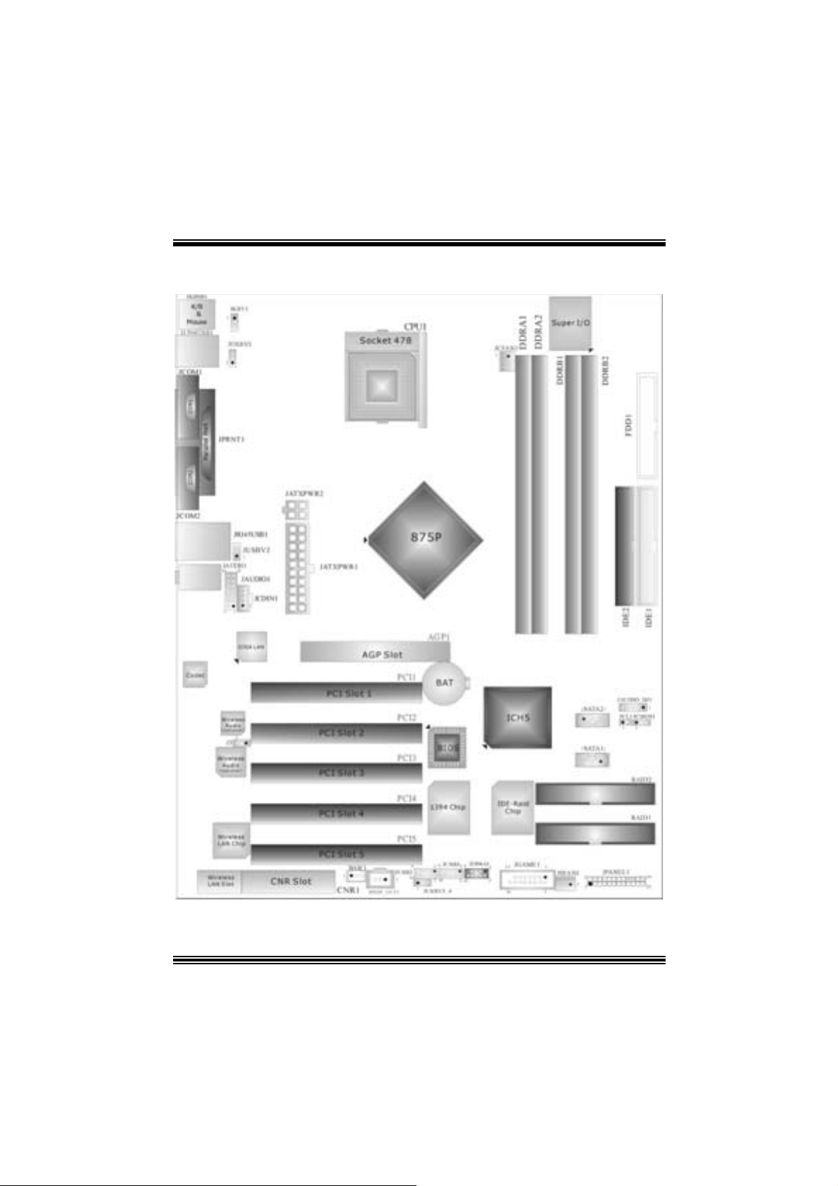
La you t o f P4TCA Pro
※ NOTE: ●repres ents the first pi n.
4
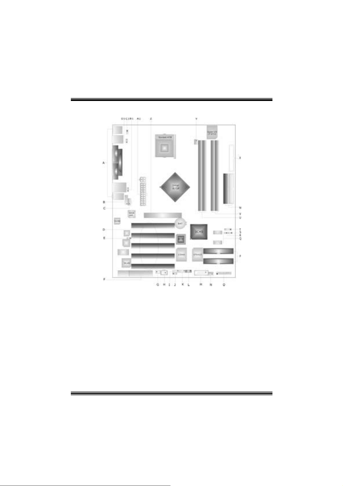
Component Index
A Back Panel Connectors B JAUDIO1: Front Aud io Heade r
C JC D IN1: CD-Ro m Aud io -In H eade r D P CI1 -5: Pe riphe ra l Co mp onent Int e rconne ct S lot s
E J3: Wirele ss Au dio Channel Sele ction (optional) F CNR1: Commu nicatio n Network R iser Slot
G JWOL1: Wake On LAN H eader H JS PD IF _OUT 1: Digi tal A udio Connector
I J US B2: Front U SB Hea de r J J USBV3 _ 4: 5V/5 VSB Selection for JUSB2 /3
K JUS B3: F ront U SB Heade r L J1394A 1: Front 1394A Heade r
M JGAME1: Game H eader N JSFAN 1: S ys tem F an H eader
O JPANEL: Front Panel Conn ecto r P RAID1 -2: Ra id Connector
Q SATA1-2: Serial ATA Connector R JCL1: Case Open Connector
S JCMOS: Clear CMOS Jumper T JAUDIO_ DJ1: Audio DJ Connector
U DDR A1-2: DDR DIMM Modu le s V DDRB1 -2 : DDR DIMM Modules
W ID E1 -2: Har d Disk Conn ectors X FDD1: Floppy Disk Co nnector
Y JCF AN1 : CPU Fan Conne cto r Z AGP1: Ac ce le ra ted Graph i cs Port S lot
A1 JA T XPW R1 -2 : A TX Powe r Con nec to r B1 J USBV2: 5V/5VSB Sel e ction for USB
C1 JKBV1: 5V/5VSB Selection for Kb / Ms D1 J USBV1: 5V/5VSB Sel e ction for USB
5
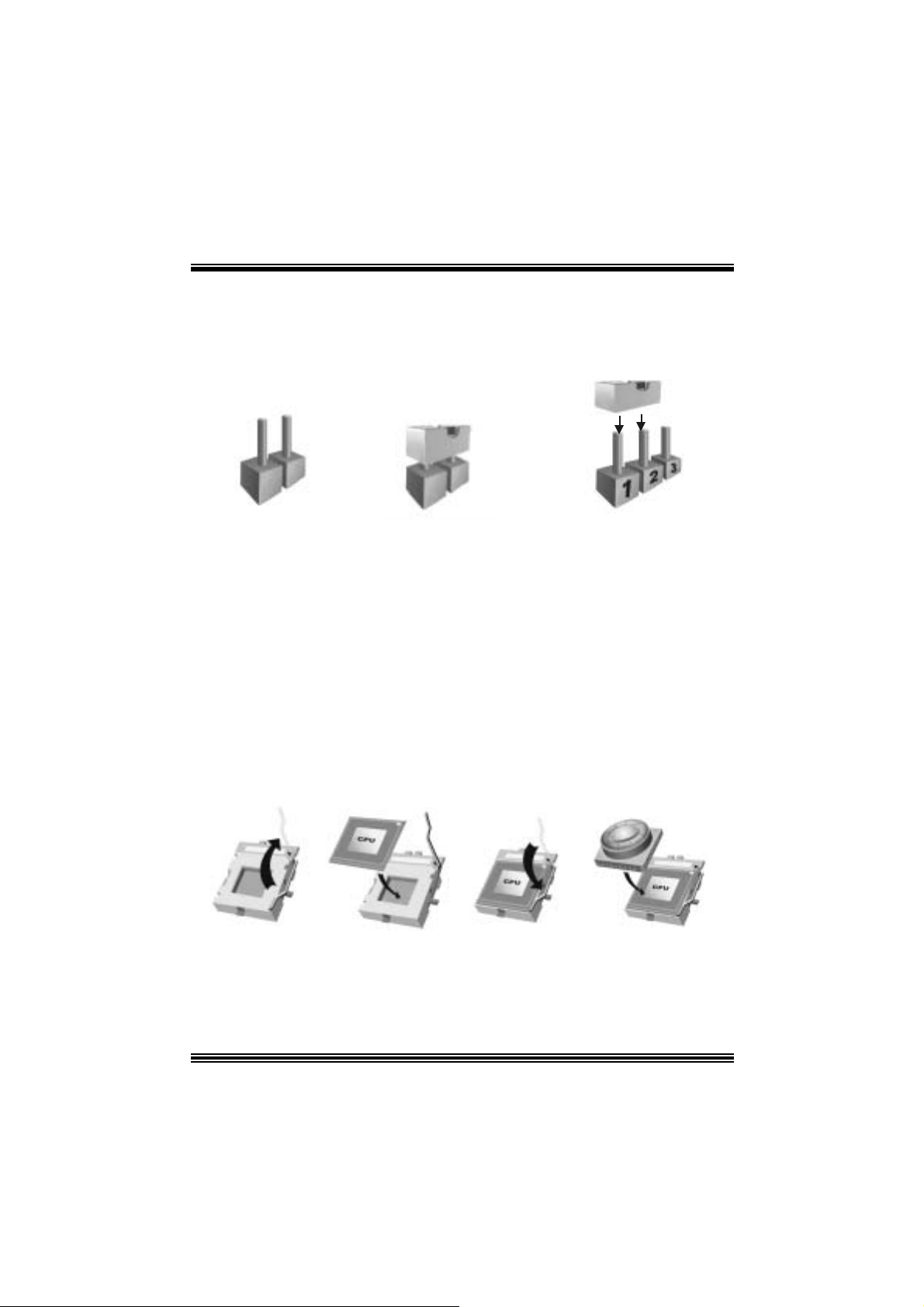
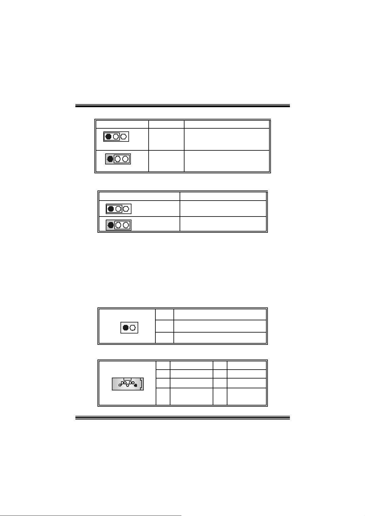
How to s e t u p Jumper
The illustration s hows how to set up jum pers. When the Jum per cap is placed on pins, t he
jumper is “close”. IF no jumper cap is placed on the pins, the jumper is ”open”. The
illust rat ion shows a 3-pin jumper whos e pin1and 2 are “close” when jumper cap is placed
on thes e 2 pins .
Jumper open Jumper close Pin1-2 close
CPU Installation
Step1: Pull the lever sideway s away from the socket and then raise the lev er up to a
90 -degree angl e.
Step2: Look for the white dot/c ut edge. The white dot/ cut edge should point wards t he lever
piv ot. The C P U will f it only in t he co rrec t orient ation.
Step3: Hold the CPU down fir mly, an d then cl ose the lever to complete the installation.
Step4: Pu t the CPU Fan on the CPU and buck le it. Con nect the CPU fan power ca ble to the
JCFA N 1. This com pletes t he installation.
Step1 Step2 Step3 Step4
6
y
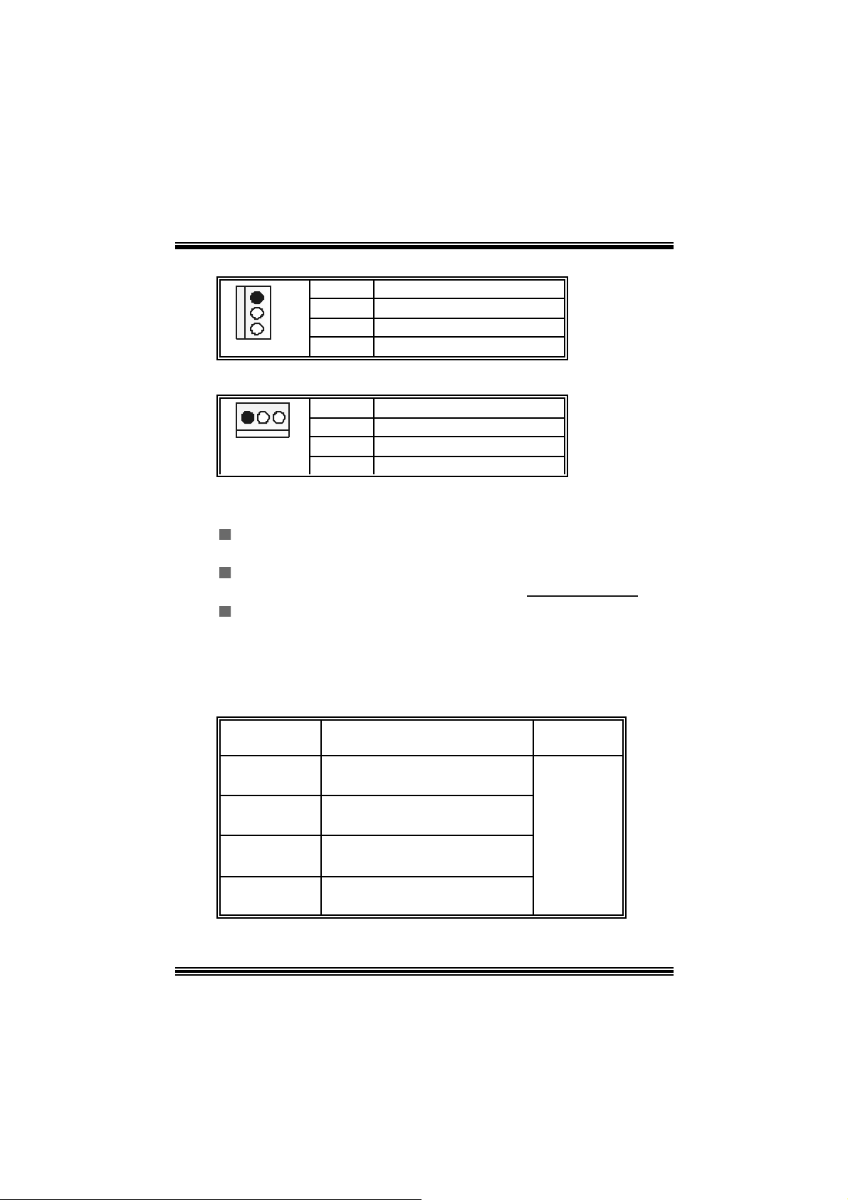
CPU Fan Headers: JCFAN1
1
JCFAN1
Pin Assignment
1
2
3
Ground
+12V
FAN RPM Sense
S ystem Fan Headers: JSFAN1
Pin Assignment
1
1
JSFAN1
2
3
Ground
+12V
FAN RPM Sense
DDR DI MM Module s: DDRA1- 2, DDRB1-2
Support s up to four DDR DIMMs(two D I MMs per channel), single-sided and/ or
double-sides.
DIMMs must be populated in identical pairs for dual-channel operation.(For
more dual c hannel operation inf orm ation please log on: www.biostar.com.tw
Support s DDR 333 or DDR 400 unregistered EC C or non-EC C DDR DI MMS.
DRAM Access Time: 2.5V Unbuffered/ Regis t ered DD R SDRAM PC1600/
PC2100 Ty pe required.
DRAM Ty pe: 128MB/ 256MB/ 512MB/ 1GB DI MM Module (184 pin)
T otal Memory Size with U nbu ffered/ R eg i s tered D I MMs
)
DIMM Socke t
Location
DDRA1 6 4MB/128MB/256MB/512MB/1GB
DDRA2 6 4MB/128MB/256MB/512MB/1GB
DDRB1 64 MB/128 MB/2 56 MB/5 12MB/1 GB
DDRB2 64 MB/128 MB/2 56 MB/5 12MB/1 GB
DDR Mod u l e To tal Memor
Size (MB)
*1
*1
*1
*1
***Only for reference***
7
Max is
4GB

Installing DDR Mod ule
1. Unlock a DIMM slot by pressing the
retaining clips outward. Align a DIMM on
t he s lot s uc h t hat t he no t c h on th e D IMM
ma t ches t he break o n the sl ot .
.
2. Insert the DIMM v ertically and firmly into
the s lot until the ret ain ing c hip s nap back in
place and the DI MM is properly s eat ed.
Serial Raid
Setting Up a RAID 0 System
The following steps lead y ou to build a R AID 0 sys t em:
1. Enter Sy s tem BIOS Setup; ens ure that Intel RAI D Technology is enabled. W hen
done, ex it Setup.
2. Upon re-boot you will s ee the I ntel R AID BIOS s t atus mess age on t he screen –
press C TRL+I to enter the Intel® RAID Option ROM user interf ace. Within this UI
select option #1 ‘C reate RAI D Volum e’. Enter a volum e nam e, press ent er, selec t
the st rip s ize (128KB is the default ), press enter, press ent er again, then press ‘Y’
to conf irm. O nc e this is done, exit t he Opt ion ROM user interfac e.
3. Begin Win dow s X P Setup by booting fro m the in stallation CD.
4. At the beginning of W indows XP Setup, press F6 to install a third-party SCSI or
RAID driver. When prompted, insert a floppy disk c ont aining t he Intel RAID driver.
Af t er reading t he floppy disk, the I ntel® 82801ER SATA RAID Controller’ will be
presented — select this driver to install.
5. Finish the W indows XP installation and ins t all all necessary driv ers.
6. Ins tall the Intel Application Accelerator R AID Edition 3.0 software v ia the CD-ROM
inc luded wit h your mo therboard or af ter downlo ading it from the Internet. T his will
add th e Intel A pplicat ion Accelerat or RAID Edition 3.0 us e r interface utility t hat c an
be used to manage the RAID con figur ation.
8
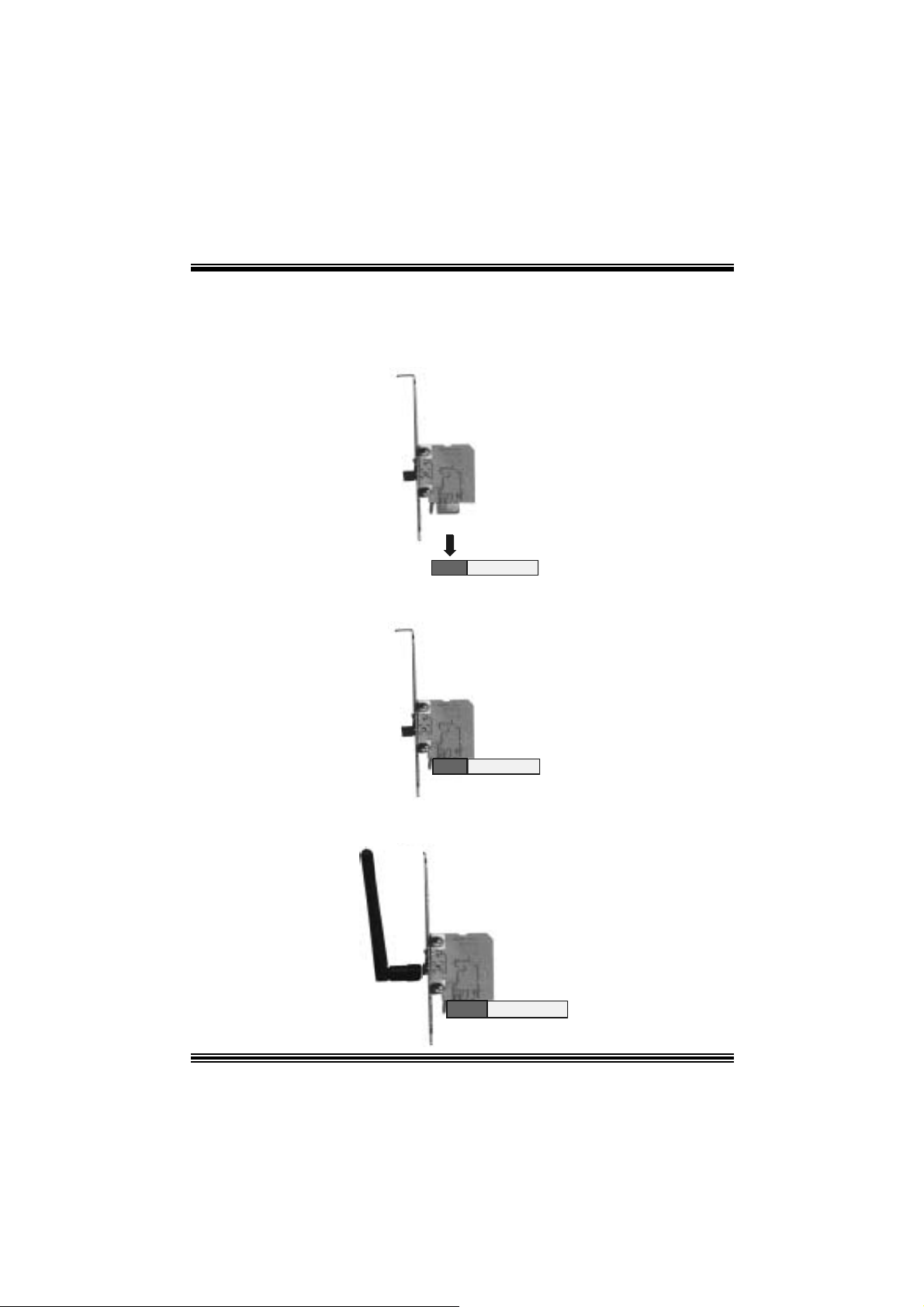
Installing Wireless LAN Card
1. Align the wireless LAN on t he slot so that the wireless LAN card m atches in
the s lot. Be sure to face the wireles s LAN card wit h its components towards
the inner part of the m otherboard as it s hows on the following picture.
2. Insert the wireless LAN card v ertically and firmly into the s lot so the wireless
card is properly seated.
3. Screw t he bracket s.
4. Ins ert the wireles s LAN ant enna by t urning it clockwis e.
9

Jumpers, Headers, Connectors & Slots
Floppy Disk Conne ctor: FDD1
The mot herboard provides a standard f loppy disk connect or that supports 360K,
720K, 1.2M, 1.44M and 2.88M f loppy disk types. This connector supports the
prov ided f loppy drive ribbon cables .
Hard Disk Connectors: IDE1/ IDE2
The motherboard has a 32-bit Enhanced PCI IDE Controller that provides PIO
Mode 0~4, Bus Master, and Ultra D MA 33/ 66/ 100/ 133 functionality. It has two
HDD connec t ors IDE1 (primary) and IDE2 (secondary).
The ID E connectors can connect a mast er and a s lav e drive, s o you can connect up
to four hard dis k drives. The firs t hard driv e should always be connect ed to IDE1.
Periphera l Component Int erconnect Slots: P CI1-5
This m ot herboard is equipped with 5 standard PCI slots. PC I stands f or Peripheral
Component Interconnect, and it is a bus standard for expansion c ards . This PCI
slot is des ignated as 32 bits.
Accelerate d Graphics Port Slot: AGP1
Y our monitor will attac h directly t o that v ideo c ard. This motherboard supports video
cards f or PCI slots, but it is also equipped with an Ac c elerat ed Graphic s Port (AGP).
An A GP c ard will take advant age of AGP tec hnology for im proved v ideo eff ic iency
and perf ormanc e, especially with 3D graphics.
Commun ication Netwo r k R ise r Slot: CNR1
The CNR specif ication is an open Industry Standard Architecture, and it defines a
ha rdw ar e scalable r iser card interfa ce, which su pports modem only.
Serial ATA Co nnector: JSATA1/JSATA2
The mot herboard has a PCI t o SATA C ont roller with 2 channels STAT interface, it
satisfy the SA T A 1 . 0 sp ec and can tr ans f e r data w it h 1.5GHz s pee d.
IDE-Raid C onnector: RAID1 /2
This c onnector supports RAID0 or RAID1 or RAID 0+1 c onf igurat ion through t he
onboard Parallel ATA (VT6410) c o nt roll er c h ip. Y ou ca n u s e the ID E f eat u re t o
set up a disk array configuration and to support additional ID E devices. However, it
can only support ma s ter mode IDE HDD.
10
9
L
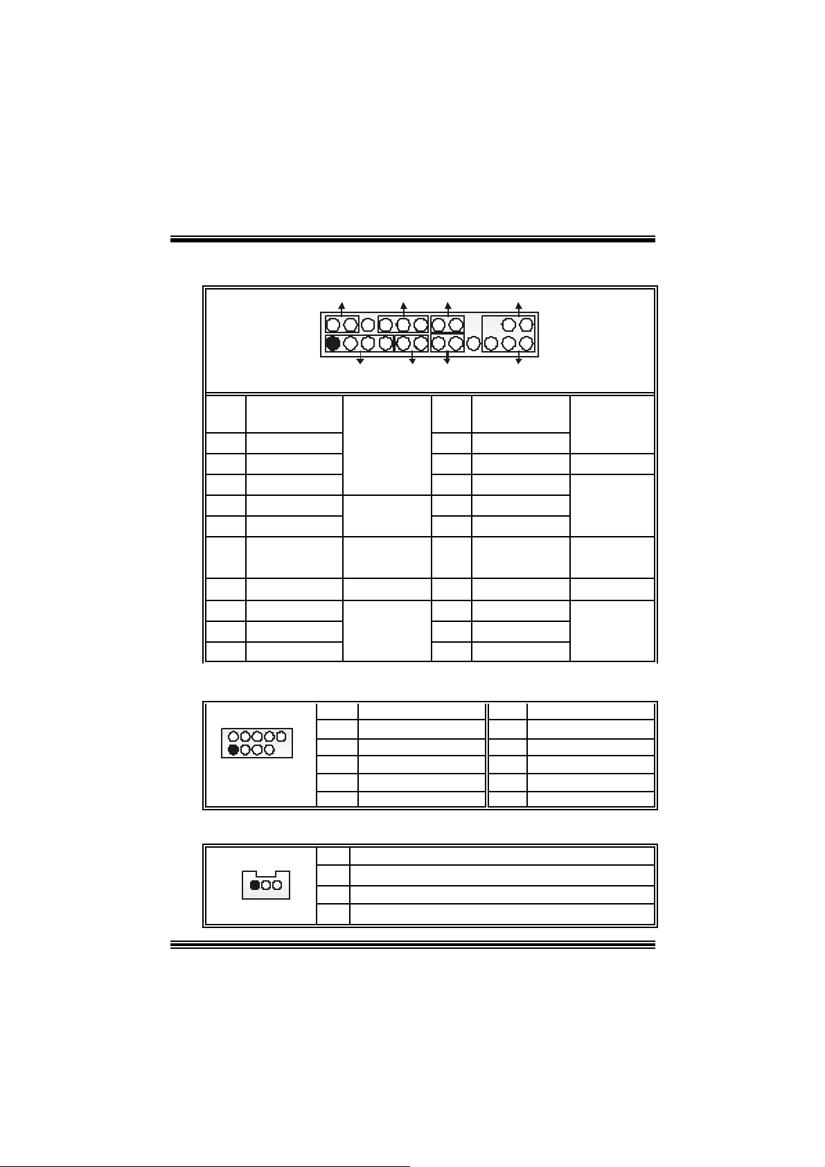
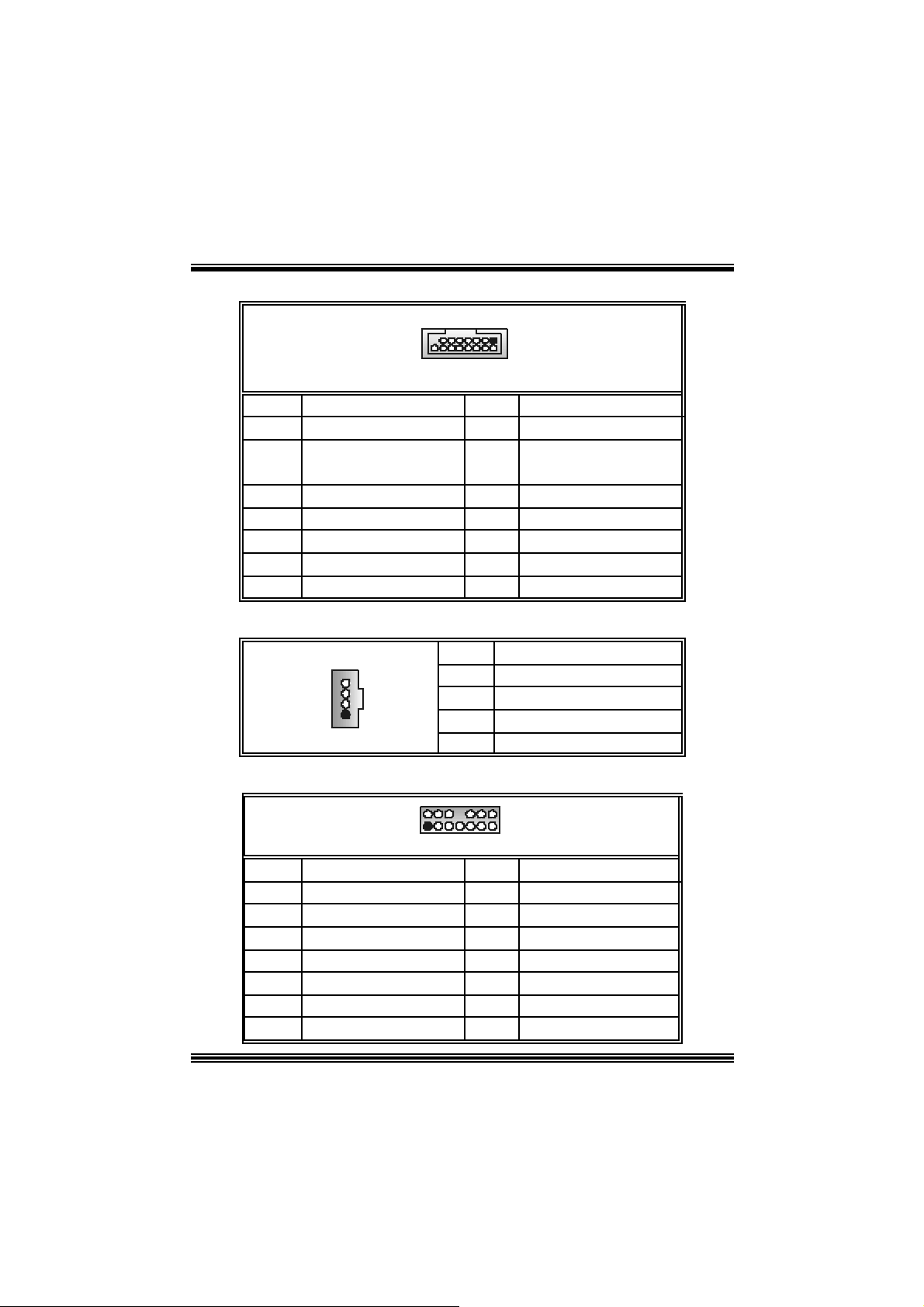
Front Pane l Conne ctor: JPANEL1
SLP
JPANE
Pin Assignment Function Pin Assignment Function
1 +5V 2 Sleep Cont rol
3 NA 4 Ground
5 NA 6 NA NA
7 Speaker
9 HDD LED (+) 10 Power LED (+)
11 H DD LED (-)
13 Ground 14 Power Butt on
15 Reset Control
17 NA 18 KEY
19 NA 20 KEY
21 +5V 22 Ground
23 IRTX
2
1
PWR_LED
SPK
HLED
RST
Speaker
Connector
8 Power LED (+)
Har d D r iv e
LED 12 Power LE D (-)
Reset
Button 16 Ground
IrDA
Connector
24 IRRX
IRON/OFF
IR
24
23
Sleep
Button
POWER
LED
Power-on
Button
IrDA
Connector
Front USB Header: JUSB2/3
Pin Assignment Pin Assignment
10
1
3
5
7
9 KEY 10 NC
+5V(fused)
USBP4-
USBP4+
Ground
2
4
6
8
+5V(fu sed)
USBP5-
USBP5+
Ground
2
1
JUSB2/3
Wake On LAN He ader: JWOL1
1
JWO L1
Pin Assignment
1 +5V Standby
2 Ground
3 Wak e up
11
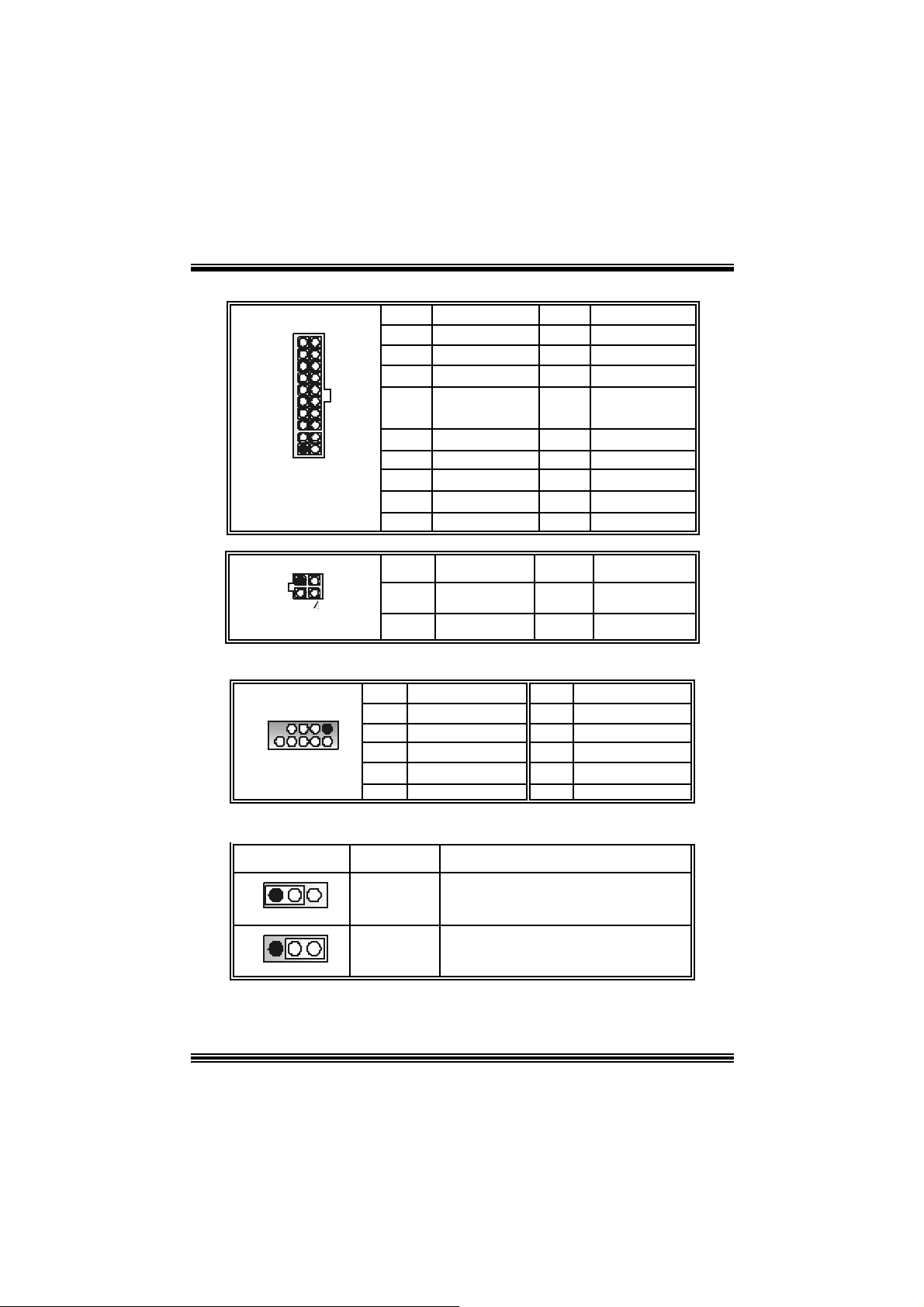
Power Conn ectors: JATXPWER1/ JATXPWR2
PIN Assignment PIN Assignment
1 +3.3V 11 +3.3V
2 +3.3V 12 -12V
3 Ground 13 Ground
4 +5V 14 PS_ON
5 Ground 15 Ground
6 +5V 16 Ground
7 Ground 17 Ground
8 PW_OK 18 -5V
9 +5V_SB 19 +5V
10 +12V 20 +5V
PIN Assignment PIN Assignment
1 +12V 3 Ground
2 +12V 4 Ground
JATXPWR1
JATXPWR2
10
20
1
11
123
Front 1394 Header: J1394A
9
10
J1394A
Pin Assignment Pin Assignment
1
1
3 Ground 4 Ground
2
5
7
9
A1+
B1+
+1 2V
KEY
2
6
8
10
5V / 5VSB Selection for KB: JKBV1
JKBV1 Assignment
Description
A1-
B1-
+1 2V
NA
1 3
Pin 1-2 clos e
1 3
Pin 2-3 clos e
+5V
+5V_S B
5V for ke yboar d and mo use
5V standby for keyb oard and mouse to
power on yo ur s yste m
12
3
5V/ 5VSB Selection for USB: JUSBV1/JUSBV3_4
JUSBV1/JUSBV3_4 Assignment Description
1 3
1-2 close
1 3
2-3 close
Clear CMOS Jumper: JCMOS1
1 3
1 3
Pin
Pin
JCMOS1 Assignment
Pin 1-2 Close
Pin 2-3 Close
+5V 5V for JUSB1 /2/3
+5V_SB 5V st andby t o power on JUSB1/ 2/
Norm al Operation (def ault)
Clear CMOS Data
※ Clear CMOS Procedures:
1. R emov e AC power line.
2. Make JCMOS1 (2-3) closed.
3. Wa it for fi ve seconds.
4. Make JCMOS1 (1-2) closed.
5. Let AC power on.
6. R eset your des ired password or clear t he C MOS dat a.
Ca se Op e n Connec tor : JCL1
12
JCL1
Pin
1
2
Assignment
Case Open Signal
Ground
Serial ATA Co nnector: JSATA1/ JSATA2
1234567
JS ATA1/ JSATA2
Pin Assignment Pin Assignment
1 Ground 2 TX+
4
5
7
TX- 4 Ground
RX- 6 RX+
Ground
13
Game Header: JGAME1
15
JGAME1
Pin Assignment Pin Assign ment
1
3
5
7
9
11
13
15
+5V
GP6
GP2
MIDI-OUTR
GP3
GP7
M IDI-INR
NC
1
216
2
4
6
8
10
12
14
16
CD-ROM Audio-In Heade r: JCDIN1
1
JCDIN1
Pin Assignment
1 Left Channel In put
2
3
4
Ground
Ground
Right Channel In put
Front Panel Audio Header: JAUDIO1
+5V
GP4
GP0
Ground
Ground
GP1
GP5
+5V
2
1
JAUDIO1
Pin Assignment Pin Assignment
1 Mic In 2 Ground
3
5
7
9
11
13
Mic Po we r
RT Line Out
Reserved
LFT Line Out
RT Line In
LET Line In
14
14
13
4
6
8
10
12
14
Audio Power
RT Line Out
Key
LFT Line Out
RT Line I n
LET Line In
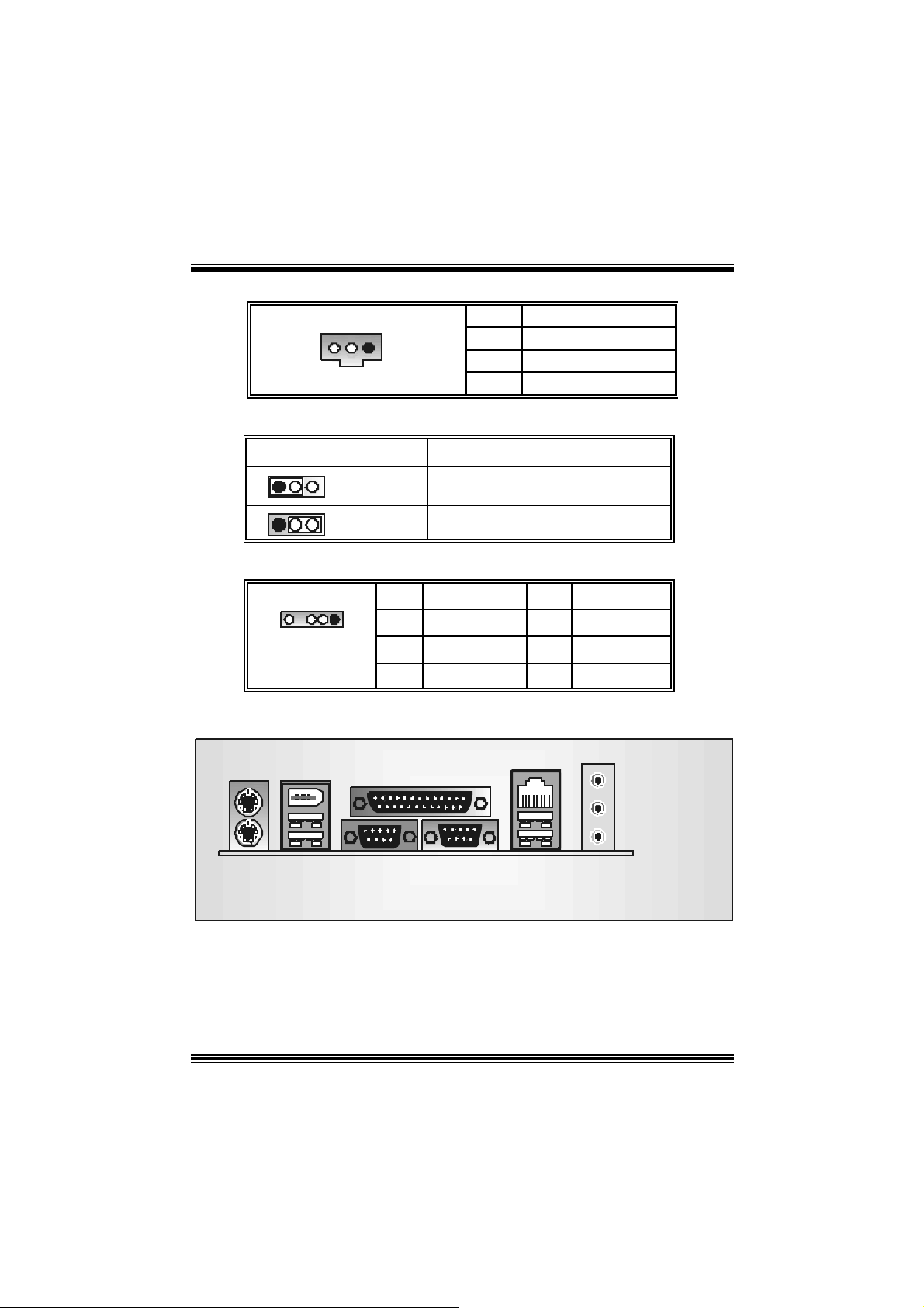
Digital Audio Connector: JSPDIF_OUT1
1
JSPDIF_OU T1
Pin Assignment
1
2
3
+5V
SPDIF_OUT
Ground
Wireless Audio Channel Selection : J3 (optional)
J3 Assignment
1 3
1 3
Pin1-2 c lose
Pin 2-3 close
AUD IO DJ Connec tor: JAUDIO_ DJ1
JAU DIO _DJ1
Pin Assignment Pin Assignment
15
1 SMBDATA 2 SMBCLK
3
INT_B
5 ATX_PWROK
B ack Panel Connectors
Mouse
Keyb oard
1394
USB
JCOM1JKBMS1
J1394USB1
Parallel
1
1 3
COM 1
3
COM2
JCOM2
Channel 0
Channel 1
4
LAN
USB
JRJ45USB1
KEY
Line In/ Surround
Speaker Out
Mic In/ Bass&Center
JAUDIO
15
StudioFun!
Introduction
StudioF un! is a media-player based on optim ized GNU/Linux distribution. It play s DVD,
VCD , MP3, Audio CD and various other known file f ormats. You can take s napshots of
video and customize the s aved images as s c reensav ers . You can also store the images on
U S B mass sto r a ge d evi ces lik e fl a sh d i sks a nd US B fl oppy d isks.
Hardware Requirements
The supported hardware list of StudioFun! grows up every day. So please check the
hwreq.txt located in the root of StudioFun! Installation CD to get the most updated
information.
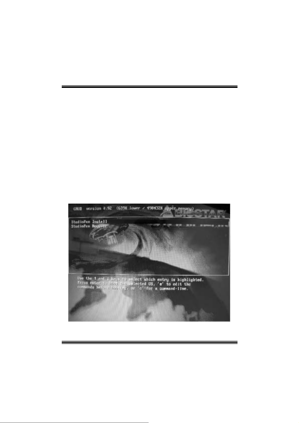
Ins tallatio n Proce dure
Ins ert the StudioFun! Installation CD in a CD /D VD ROM drive and let the system boot
through the CD. The disk will boot and bring up the grub boot loader installation menu.
Two opt ions are specif ied.
16

Installation
This option will do the basic installation of the distribution. The installation works on
pre-inst alled windows or GNU / Linux dist ribution.
On select ing the ’ins t allation’ option t he installer boots and dis plays a dialog box indic ating
the s pace required and waits f or a confirm ation. Selecting Ok will c ontinue the ins tallation
while select ing Canc el will t erm inate t he installation and reboot the mac hine.
If Windows or GNU/Linux is the only OS ins t alled on the hard disk with no f ree space, it will
resize the part it ion, either NTFS or FAT32 or ext 2, and inst all St udioFun!. In case the hard
disk has a 128MB of f ree space available, the installation will use the fre e space.
Aft er installing the base system y ou will be prompt ed to s elect the res olution f rom the
following choice s
1. 1024x768 (rec om m ended)
2. 800x 600
3. 640x 480
Select the desired res olut ion. The default is 1024x768 for high-end graphic s.
Nex t y ou will be prom pted to c hoose the DVD area/region s elect ion code. C hoose t his
bas ed on the ty p e of D VDs y ou will b e playing.
The installation procedure will then probe f or t he ty pe of m ouse installed. The distribut ion
currently supports PS/ 2, USB and Serial mice. In case of serial m ouse you will hav e to
mov e the mouse when prompt ed. The ot her two are probed and inst alled automatic ally.
The installation procedure will now finish, t he CD is ejected and a dialog box prompting t o
reboot t he m achine is dis play ed. Pres s OK butt on and enjoy StudioFun!.
3.1.1 Error Messages
1. Media c orrupted!! Pleas e check the media! The CD -RO M is corrupt ed.
2. Extract ion of base sy s tem failed!! Pleas e try again lat er!! The C D -ROM is corrupted.
3. Unsupported hardware found, Aborting... If you try to install StudioFun! on an
unsupported and undocumented hardware the abov e error m ess age is popped.
4. N o device found! This error message is given if t here is no hard disk in the sy stem.
17
Recovery
In cas e of a MBR c orruption, this option s hould be used. It will auto m atic ally p robe the hard
disk master boot record and f ind out the installed operating sys tem (s). On success it will
re-install the boot loader with correct options in t he MBR. Any c ustom boot loader option
spec if ied from other GNU/Linux installations will get over written by the newly probed one.
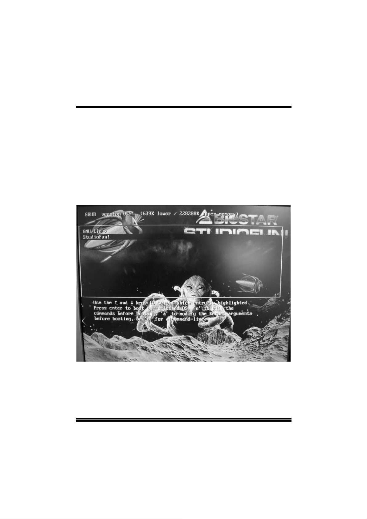
B o oting to S t udioF un!
Aft er Installation is over, rem ove the CD from the CD-ROM and res t art the machine. After
the machine reboots, you will get the GRUB boot loader menu screen. Select the
StudioF un opt ion to boot to the St udioFun! partition.
After comple te bo ot up, you get to th e main Des ktop screen. Th e followi ng section is
18
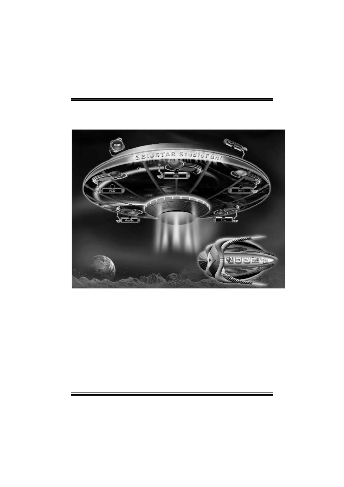
a com plete descript ion of the Desktop applicat ion.
Desktop
This is t he m ain shell of t he StudioFun s oft ware. It basic ally c ompris es of t wo categories,
one is the main "media control" part and t he other is the "control panel".
Media control
The media c ontrol part of t he D eskt op has the following controls:
1. VCD
This c ontrol will glo w whenever a VCD is d etect e d in a DVD/CD-R OM driv e. The VCD will
be auto-play ed only when it is put in to the driv e when the D esktop (StudioFun! shell) is up
and running, otherwise, t he control will sim ply glow t o inform the us er about a VCD present
in the DVD/CD-R OM drive.
19

2. DVD
This control will glow whenever a DVD is detected in a DVD drive. The DVD will be
auto-played only when it is put in to t he drive when the D esk top (StudioFun! shell) is up
and running, otherwise, the control will simply glow to inf orm the user about a DVD pres ent
in t h e DVD/ CD - ROM.
3. MP3
This c ontrol will glo w whenever a MP3 is dete cted in a DV D/CD-ROM drive. The MP3 will
be auto-play ed only when it is put in to the driv e when the D esktop (StudioFun! shell) is up
and running, otherwis e, t he control will s im ply glow t o inf orm t he user about a MP3 present
in the DVD/CD-R OM drive.
4. AU DIO
This c ontrol will glow whenev e r a AUDI O is detected in a D V D/CD -R OM drive. The AUDIO
will be aut o-played o nly when it is put in to the driv e whe n t he Deskt op (Stud ioFu n! shell) is
up and running, otherwise, the control will s imply glow to inf orm the user about a AU DI O
present in t he DVD/CD-ROM driv e.
5. FILE
This c ontrol will glow whenever a File CD (C Ds with other media type files ) is detec t ed in a
DVD/CD-ROM driv e. The F ile CD will be auto-played only when it is put in to the driv e
when the D esktop (StudioFun! shell) is up and running, otherwise, the cont rol will s im p ly
glow to inform the user about a F ile CD present in t he D VD/CD -R OM driv e.
6. EJECT MEDIA
This cont rol when c lick ed will eject any MP3 or File CDs f rom any of the D VD/CDR OM
drives . In c ase t here were no MP3 or F ile CDs it will ejec t th e default medium, (i.e. ), the
CD -ROM driv e in c ase if the user has bot h DVD/CD-ROM driv e or else it will eject the
default DVD /CD-ROM drive .
7. EXIT
This is the "Power on/ off" control of the D esktop (StudioFun! shell).
Co nt ro l Pa nel
Cont rol panel part has f iv e icons, which are shortcuts to other applications present in the
StudioFun sof tware. Tool tips are prov ided on the icons when the mouse is rolled over
them.
20
 Loading...