

Page 1

The DCode
™
Universal Mutation
Detection System
Catalog Numbers
170-9080 through 170-9104
For technical service call your local Bio-Rad office or in the U.S., call 1-800-4BIORAD (1-800-424-6723)
Page 2

Warranty
The DCode universal mutation detection system lid, tanks, casting stand, gradient mixer,
and accessories are warranted against defects in materials and workmanship for 1 year. If
any defects occur during this period, Bio-Rad will repair or replace the defective parts at our
discretion, without charge. The following defects, however, are excluded:
1. Defects caused by improper operation.
2. Repair or modification done by anyone other than Bio-Rad Laboratories or an authorized agent.
3. Damage caused by substituting alternative parts.
4. Use of fittings or spare parts supplied by anyone other than Bio-Rad Laboratories.
5. Damage caused by accident or misuse.
6. Damage caused by disaster.
7. Corrosion caused by improper solvent†or sample.
This warranty does not apply to parts listed below:
• Fuses
• Glass plates
• Electrodes
For any inquiry or request for repair service, contact Bio-Rad Laboratories. Inform
Bio-Rad of the model and serial number of your instrument.
Important: This Bio-Rad instrument is designed and certified to meet EN61010-1* safety
standards. Certified products are safe to use when operated in accordance with the instruction
manual. This instrument should not be modified or altered in any way. Alteration will:
• Void the manufacturer’s warranty
• Void the EN61010-1 safety certification
• Create a potential safety hazard
Bio-Rad Laboratories is not responsible for any injury or damage caused by the use of this
instrument for purposes other than those for which it is intended, or by modifications of the
instrument not performed by Bio-Rad Laboratories or an authorized agent.
The Model 475 Gradient Delivery System is covered by U.S. patent number 5,540,498.
Practice of PCR is covered by U.S. patent numbers 4,683,195; 4,683,202; 4,899,818
issued to Cetus Corporation, which is a subsidiary of Hoffmann-LaRoche Molecular Systems,
Inc. Purchase of any of Bio-Rad’s PCR-related products does not convey a license to use
the PCR process covered by these patents. To perform PCR, the user of these products must
obtain a license.
© 1996 Bio-Rad Laboratories
All Rights Reserved
† The DCode system tank is not compatible with chlorinated hydrocarbons (e.g., chloroform), aromatic hydrocarbons (e.g., toluene,
benzene), or acetone. Use of organic solvents voids all warranties.
* EN61010-1 is an internationally accepted electrical safety standard for laboratory instruments.
Page 3

Table of Contents
Section 1 General Safety Information ..........................................................1
1.1 Caution Symbols........................................................................................1
1.2 Precautions During Set-up .........................................................................1
1.3 Precautions During a Run..........................................................................1
1.4 Precautions After a Run.............................................................................2
1.5 Safety ........................................................................................................2
Section 2 Introduction ...................................................................................2
2.1 Introduction to Mutation Detection Technology...........................................2
Section 3 Product Description......................................................................2
3.1 Packing List ...............................................................................................2
3.2 System Components and Accessories.......................................................5
Section 4 Denaturing Gel Electrophoresis (DGGE, CDGE, TTGE)............11
4.1 Introduction to Denaturing Gradient Gel Electrophoresis (DGGE) ............11
Reagent Preparation................................................................................13
Gel Volumes ............................................................................................15
Sample Preparation .................................................................................16
Temperature Controller............................................................................17
Preheating the Running Buffer.................................................................18
Assembling the Perpendicular Gradient Gel Sandwich ............................18
Casting Perpendicular Gradient Gels .......................................................22
Assembling the Parallel Gradient Gel Sandwich ......................................24
Casting Parallel Gradient Gels .................................................................26
4.2 Introduction to Constant Denaturing Gel Electrophoresis (CDGE)............28
Reagent Preparation................................................................................29
Gel Volumes ............................................................................................31
Sample Preparation .................................................................................31
Temperature Controller............................................................................32
Preheating the Running Buffer.................................................................33
Assembling the CDGE Gel Sandwich ......................................................33
Casting CDGE Gels.................................................................................35
4.3 Introduction to Temporal Temperature Gradient Gel Electrophoresis
(TTGE) ....................................................................................................36
Calculating the Run Parameters ..............................................................37
Reagent Preparation................................................................................38
Gel Volumes ............................................................................................40
Sample Preparation .................................................................................40
Preheating the Running Buffer.................................................................40
Assembling the TTGE Gel Sandwich .......................................................40
Temperature Controller............................................................................41
Casting TTGE Gels..................................................................................43
Section 5 Heteroduplex Analysis................................................................44
5.1 Introduction to Heteroduplex Analysis ......................................................44
5.2 Reagent Preparation................................................................................45
5.3 Gel Volumes ............................................................................................47
5.4 Sample Preparation .................................................................................48
5.5 Temperature Controller............................................................................48
5.6 Adding the Running Buffer .......................................................................49
5.7 Assembling the Heteroduplex Analysis Gel Sandwich .............................50
Page 4

5.8 Casting Heteroduplex Analysis Gels ........................................................51
Section 6 Single-Stranded Conformational Polymorphism (SSCP) .........52
6.1 Introduction to SSCP ..............................................................................52
6.2 Reagent Preparation ...............................................................................54
6.3 Gel Volumes ............................................................................................56
6.4 Sample Preparation ................................................................................56
6.5 Temperature Controller............................................................................57
6.6 Cooling the Running Buffer and Chiller Settings.......................................58
6.7 Assembling the SSCP Gel Sandwich.......................................................58
6.8 Casting SSCP Gels .................................................................................60
Section 7 Protein Truncation Test (PTT).....................................................61
7.1 Introduction to PTT .................................................................................61
7.2 Reagent Preparation ...............................................................................62
7.3 Gel Volumes ............................................................................................64
7.4 Sample Preparation .................................................................................64
7.5 Temperature Controller............................................................................65
7.6 Adding the Running Buffer .......................................................................66
7.7 Assembling the PTT Gel Sandwich..........................................................66
7.8 Casting PTT Gels ....................................................................................68
Section 8 Electrophoresis...........................................................................69
8.1 Assembling the Upper Buffer Chamber....................................................69
8.2 Sample Loading.......................................................................................71
8.3 Running the Gel.......................................................................................71
8.4 Removing the Gel ....................................................................................73
8.5 Staining and Photographing the Gel ........................................................74
Section 9 Troubleshooting Guide ..............................................................75
9.1 Equipment ..............................................................................................75
9.2 Applications .............................................................................................77
Section 10 Specifications..............................................................................81
Section 11 Maintenance ................................................................................82
Section 12 References...................................................................................82
Section 13 Instruments and Reagents for Mutation Detection
Electrophoresis ..........................................................................83
Page 5
Section 1
General Safety Information
1.1 Caution Symbols
Read the manual before using the DCode system. For technical assistance, contact your
local Bio-Rad Office or in the U.S., call Technical Services at 1-800-4BIORAD (1-800-424-6723).
DC power to the DCode system is supplied by an external DC voltage power supply. This power
supply must be ground isolated so that the DC voltage output floats with respect to ground. All BioRad power supplies meet this important safety requirement. Regardless of which power supply
is used, the maximum specified operating parameters for the system are:
• Maximum voltage limit 500 VDC
• Maximum power limit 50 watts
AC current for controlling temperature to the system, and DC current for electrophoresis,
provided by the external power supply, enter the unit through the lid assembly, which provides
a safety interlock. DC current to the cell is broken when the lid is removed. Do not attempt to circumvent this safety interlock. Always disconnect the AC cord from the unit and the cord
from the DC power supply before removing the lid, or when working with the cell.
Definition of Symbols
Caution, risk of electric shock.
Caution
Caution, hot surface.
1.2 Precautions During Set-up
• Do not use near flammable materials.
• Always inspect the DCode system for damaged components before use.
• Always place the DCode system on a level bench-top.
• Always place the lid assembly on the buffer tank with the AC and DC power cords
disconnected.
• Always connect the system to the correct AC and DC power sources.
1.3 Precautions During a Run
• Do not run the pump when it is dry. Always add buffer to the “Fill” line when
pre-chilling and/or preheating the buffer; always keep the buffer below “Max” level during
electrophoresis.
• Do not touch any wet surface unless all the electrical sources are disconnected.
• Do not put anything on the top surface of the DCode system module.
1
Page 6

1.4 Precautions After a Run
• Always turn off power switches and unplug all cables to DC and AC sources. Allow the
heater tube to cool down (approximately 1 minute) before removing it from the tank. The
ceramic tube may be very hot after shut-down. Do not touch the ceramic tube after turn-
ing off the power.
• Do not cool the hot ceramic tube in cool liquids.
• Always store the electrophoresis/temperature control module on the aluminum DCode
lid stand for maximum stability. Caution: the heater tube may be hot after use
1.5 Safety
This instrument is intended for laboratory use only
This product conforms to the “Class A” standards for electromagnetic emissions intended for laboratory equipment applications. It is possible that emissions from this product may
interfere with some sensitive appliances when placed nearby or in the same circuit as those
appliances. The user should be aware of this potential and take appropriate measures to
avoid interference.
Section 2
Introduction
2.1 Introduction to Mutation Detection Technology
Detecting single base mutations is of utmost importance in the field of molecular genetics.
Screening for deletions, insertions, and base substitutions in genes was initially done by Southern
blotting. Many techniques have been developed to analyze the presence of mutations in a DNA
target. The most common methods include: Single-Strand Conformational Polymorphism
1
(SSCP), Denaturing Gradient Gel Electrophoresis2(DGGE), carbodiimide3(CDI), Chemical
Cleavage of Mismatch4(CCM), RNase cleavage,5Heteroduplex analysis,6and the Protein
Truncation Test7(PTT). A new technique for mutation detection is Temporal Temperature
Gradient Gel Electrophoresis8(TTGE). Bio-Rad reduced this technique to a simple, reproducible
method on the DCode system. TTGE uses a polyacrylamide gel containing a constant concentration of urea. During electrophoresis, the temperature is increased gradually and uniformly. The result is a linear temperature gradient over the course of the electrophoresis run. Many
labs used combination of methods to maximize mutation detection efficiency.
The DCode system is a vertical electrophoresis instrument for the detection of gene
mutations. The DCode system can be used to perform any vertical gel-based mutation
detection method. The system is optimized for DGGE, CDGE, TTGE, SSCP, PTT and
Heteroduplex Analysis. Some of the advantages of the DCode system include uniform buffer
temperature around the gel, buffer circulation, buffer temperature runs from 5 to 70 °C and a
modular design to allow customization.
Section 3
Product Description
3.1 Packing List
The DCode system is shipped with the following components. If items are missing or damaged, contact your local Bio-Rad office.
2
Page 7

The DCode System for DGGE (10 cm and 16 cm systems)
Item Quantity
Instruction manual 1
Warranty card (please complete and return) 1
Electrophoresis/temperature control module 1
Electrophoresis tank 1
Casting stand with sponges 1
Sandwich core 1
DCode lid stand 1
16 cm glass plates (16 cm system) 2 sets
10 cm glass plates (10 cm system) 2 sets
Sandwich clamps 2 sets
Spacers, grooved, 1 mm 2 sets
Middle spacer, 1 mm (10 cm system) 2
Prep comb, 1 well, 1 mm (16 cm system) 2
Prep comb, 2 well, 1 mm (10 cm system) 2
16-well comb, 1 mm 1
Comb gasket for 0.75 & 1 mm spacers 1
Comb gasket holder 1
Model 475 gradient former 1
Syringes: 10 ml, 30 ml 2 each
Tubing 3 feet
Luer couplings 4
Luer syringe locks 2
Syringe sleeves 4
Syringe cap screws 2
Y-fitting 5
Control reagent kit for DGGE, CDGE, TTGE 1
DCode System for CDGE
Item Quantity
Instruction manual 1
Warranty card (please complete and return) 1
Electrophoresis/temperature control module 1
Electrophoresis tank 1
Casting stand with sponges 1
Sandwich core 1
DCode lid stand 1
Glass plates, 16 cm 2 sets
Sandwich clamps 2 sets
Spacers, 1 mm 2 sets
20-well combs, 1 mm 2
Control reagent kit for DGGE, CDGE, TTGE 1
3
Page 8

DCode System for TTGE
Item Quantity
Instruction manual 1
Warranty card (please complete and return) 1
Electrophoresis/temperature control module 1
Electrophoresis tank 1
Casting stand with sponges 1
Sandwich core 1
DCode lid stand 1
Glass plates, 16 cm 2 sets
Sandwich clamps 2 sets
Spacers, 1 mm 2 sets
20-well combs, 1 mm 2
Control reagent kit for DGGE, CDGE, TTGE 1
DCode System for SSCP
Item Quantity
Instruction manual 1
Warranty card (please complete and return) 1
Electrophoresis/temperature control module 1
Electrophoresis cooling tank 1
Casting stand with sponges 1
Sandwich core 1
DCode lid stand 1
Sandwich clamps 2 sets
Glass plates, 20 cm 2 sets
Spacers, 0.75 mm 2 sets
20-well combs, 0.75 mm 2
Control reagent kit for SSCP 1
DCode System for Heteroduplex Analysis
Item Quantity
Instruction manual 1
Warranty card (please complete and return) 1
Electrophoresis/temperature control module 1
Electrophoresis tank 1
Casting stand with sponges 1
Sandwich core 1
DCode lid stand 1
Sandwich clamps 2 sets
Glass plates, 20 cm 2 sets
Spacers, 0.75 mm 2 sets
20-well combs, 0.75 mm 2
Control reagent kit for Heteroduplex Analysis 1
4
Page 9

DCode System for Protein Truncation Test
Item Quantity
Instruction manual 1
Warranty card (please complete and return) 1
Electrophoresis/temperature control module 1
Electrophoresis tank 1
Casting stand with sponges 1
Sandwich core 1
DCode lid stand 1
Sandwich clamps 2 sets
Glass plates, 20 cm 2 sets
Spacers, 1 mm 2 sets
20-well comb, 1 mm 2
3.2 System Components and Accessories
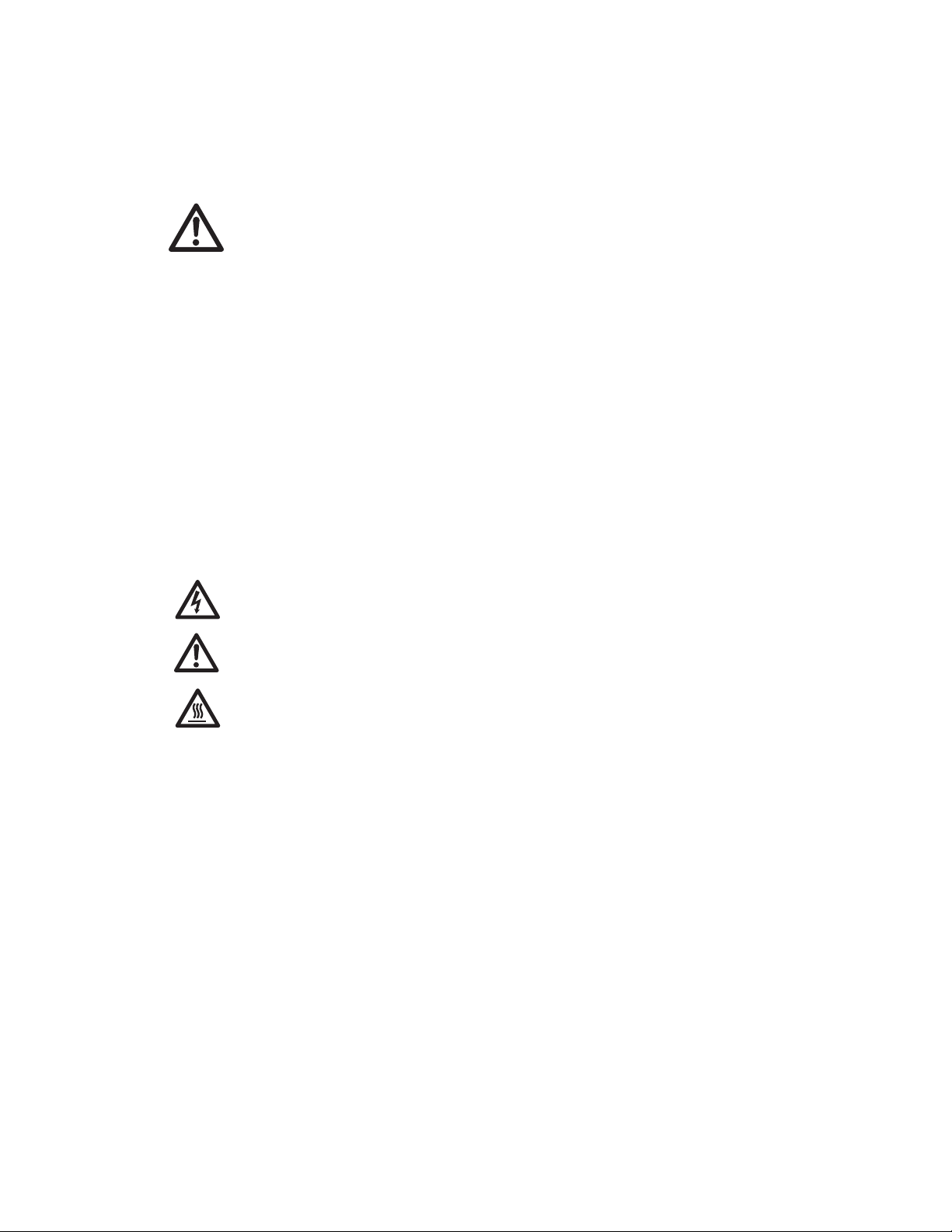
Fig. 3.1. The DCode system.
System Components
and Accessories Description
Electrophoresis Tank The electrophoresis tank is a reservoir for the running buffer.
Electrophoresis Cooling Tank The electrophoresis cooling tank has two ceramic cooling
(SSCP only) fingers inside the electrophoresis tank (Figure 3.2). Two
quick-release connectors are connected to an external
chiller to chill the running buffer. The electrophoresis
cooling tank should not be used for heated buffer runs
(i.e., DGGE, CDGE or TTGE).
Fig. 3.2. Electrophoresis cooling tank.
5
Model 475
Gradient Former
Electrophoresis/temperature
control module
Casting stand with
perpendicular assembly
Electrophoresis tank
Core
Casting
stand
Ceramic
cooling
fingers
Page 10
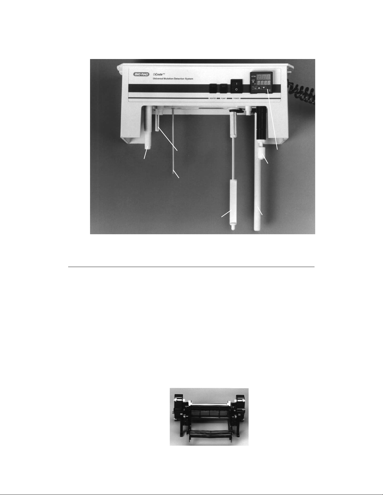
Fig. 3.3. Electrophoresis/Temperature Control Module.
System Components
and Accessories Description
Electrophoresis/Temperature The control module contains the heater, stirrer, pump,
Control Module and electrophoresis leads to operate the DCode
system (Figure 3.3). Combined with the lower buffer tank,
the control module acts to fully enclose the
system. The control module should be placed so that the
tip of the stirring bar fits inside the support hole of the tank.
The clear loading lid is a removable part that contains four
banana jacks which function as a safety interlock. It should
be left in place at all times except while loading samples.
Core The sandwich core holds one gel assembly on each side
(Figure 3.4). When attached, each gel assembly forms one
side of the upper buffer chamber. The inner plate is
clamped against a rubber gasket on the core to provide a
greaseless seal for the upper buffer chamber.
Fig. 3.4. Core
6
Buffer level
interlock
Temperature
sensor
Buffer
recirculation pump
Buffer
recirculation port
Ceramic heater
Stirrer
Temperature
controller
Page 11
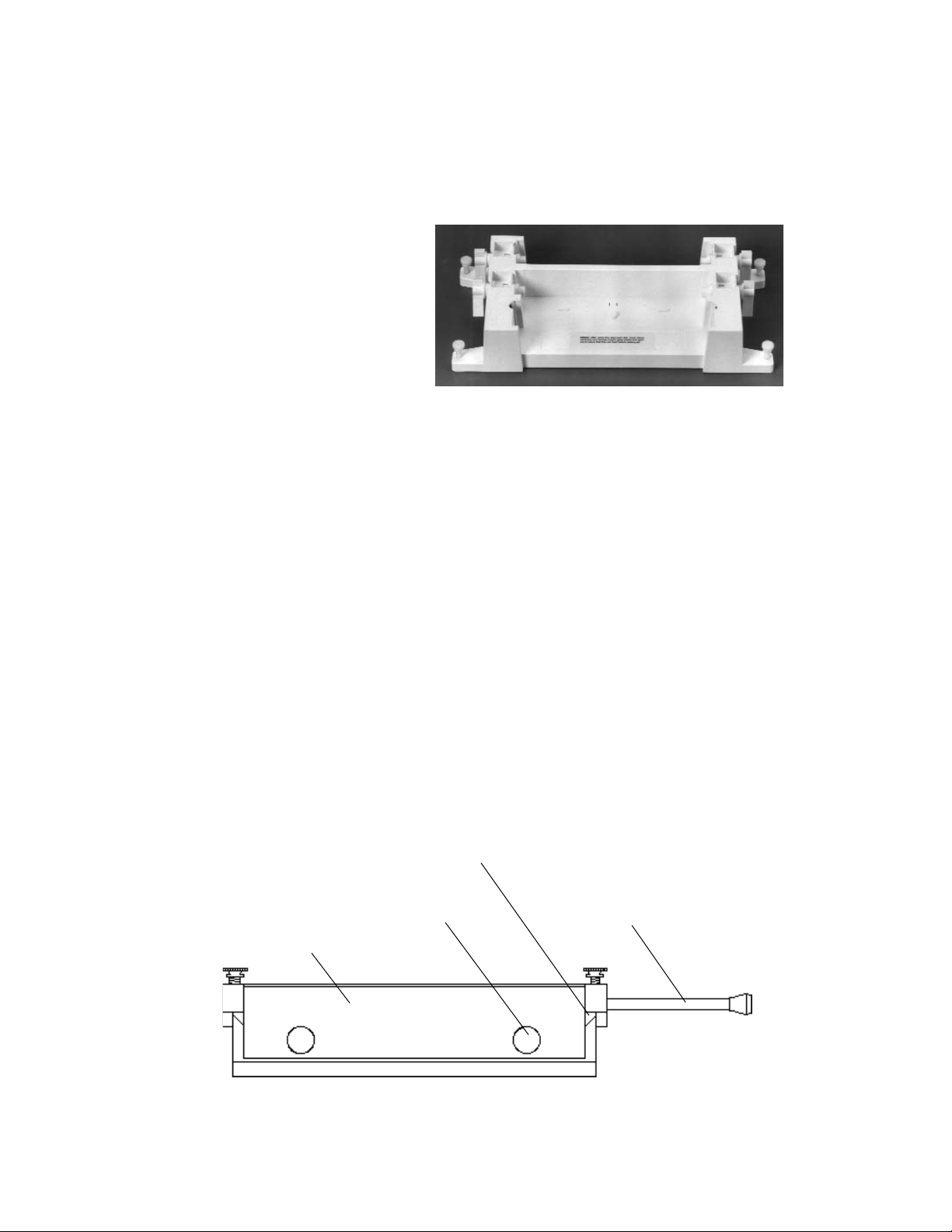
Casting Stand The casting stand holds the gel sandwich upright
while casting a gel (Figure 3.5). With the cam levers
engaged, the sponge seals the bottom of the gel
while the acrylamide polymerizes.
Fig. 3.5. Casting Stand.
Sandwich Clamps The sandwich clamps consist of a single screw
mechanism which makes assembly, alignment, and
disassembly of the gel sandwich an effortless task.
The clamps exert an even pressure over the entire
length of the glass plates. A set consists of a left and
right clamp.
Alignment Card The alignment card simplifies sandwich assembly by
keeping the spacers in the correct position.
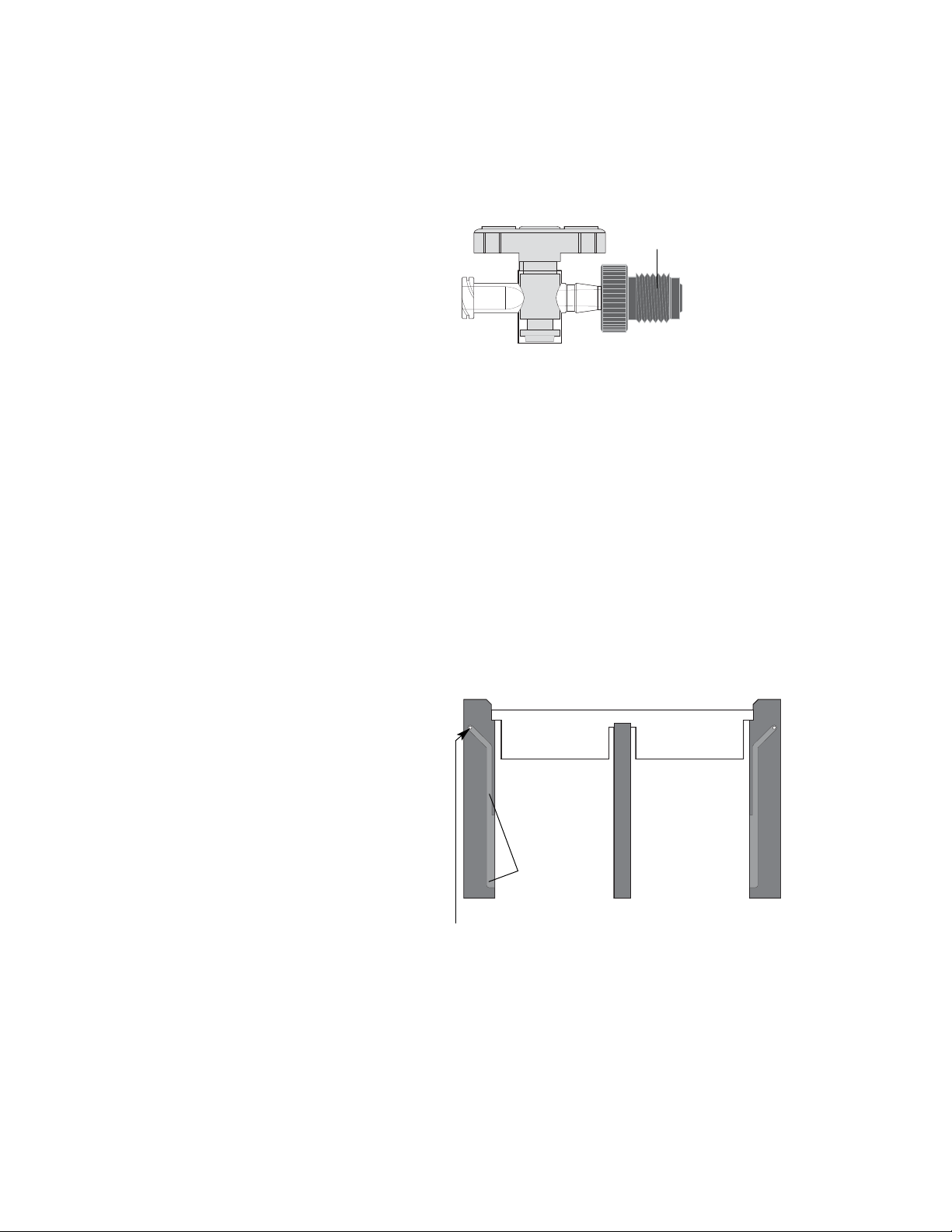
Comb Gasket Holder The comb gasket holder holds the comb gasket that
prevents (DGGE only) leakage of acrylamide during gel
casting (Figure 3.6). The front of the holder has two
screws which are used to secure the comb gasket
against the glass plate. The top of the comb gasket
holder also has two tilt rod screws which control the
position of the tilt rod during gel casting. The opposite
side of the comb gasket holder has two vent ports. There
are two sizes of comb gasket holder: a 1 mm size for
1 mm and 0.75 mm spacer sets and a 1.5 mm size for
the 1.5 mm spacer set.
Fig. 3.6. Comb gasket holder.
7
Notched step
Gasket holder
Comb gasket screws
Tilt rod
Page 12
Stopcocks (DGGE only) The gel solution is introduced via the stopcock at the
inlet port on the sandwich clamp when casting a perpendicular gel (Figure 3.7).
Fig. 3.7. Stopcock
Comb and Spacer Set The 7.5 x 10 cm gel format consist of two “mirror image
(DGGE only)spacers, one middle spacer and a dual
prep comb for two 7.5 x 10 cm gels (Figure 3.8). The
spacers have a groove and injection port hole for
casting. The middle spacer between the two gels fits
into the middle notch of the dual comb and allows the
air to escape through the comb gasket holder vent port.
The 16 x 16 cm gel format consist of two different
spacers, one with the groove and injection port hole
for casting and one with a short groove toward the
injection port hole for air to escape. A single prep comb
without a middle spacer is provided with the 16 x 16 cm
gel format.
Fig. 3.8. Dual prep comb and spacer set for two 7.5 x 10 cm gels.
Comb and Spacer Set Different types of combs and spacers are provided with
the different DCode systems. Spacer lengths are
10 cm, 16 cm or 20 cm, with a thickness of 0.75 or
1.0 mm. Combs come with 16 or 20 wells and a
thickness of 0.75 or 1.0 mm.
8
Inlet fitting
Injection port holes
groove
Page 13
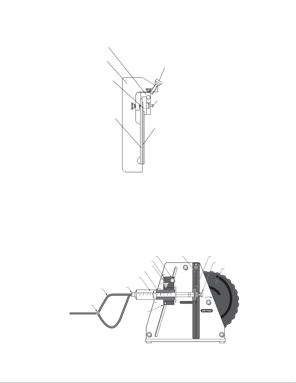
Fig. 3.9. Pressure clamp.
Pressure Clamp The pressure clamp provides consistent pressure to
the (DGGE only) comb gasket before securing it to the plate assembly
to provide a seal (Figure 3.9).
DCode Lid Stand The DCode lid stand provides a stand when the
electrophoresis/temperature control module (lid) is not in
use. The stand must be used to properly support and
protect the lid components when the lid is not on the
electrophoresis tank.
Fig. 3.10. Model 475 Gradient Delivery System.
9
Gasket holder
Comb gasket
Air vent
Pressure clamp
Pressure
clamp screw
Large glass plate
Small glass plate
Luer fitting
VOLUME
10 ML SYRINGE
4
MODEL 475
GRADIENT DELIVERY
SYSTEM
THIS SIDE FOR
HIGH DENSITY SOLUTION
(BOTTOM FILLING)
LOW DENSITY SOLUTION
(TOP FILLING)
Syringe holder
DELIVER
Cam
Plunger cap screw
Plunger cap
Lever
Y-Fitting
Tubing
Syringe
Syringe sleeve
Syringe holder screw
Volume setting indicator
Volume adjustment screw
1234 5 6 78910
10
7
6
5
5 6
Page 14
Model 475 System Components
Description (DGGE System only)
Syringe Two pairs each of 10 and 30 ml disposable syringes are
provided. The 10 ml syringes are for gel volumes less than
10 ml. The 30 ml syringes are for gel volumes greater than
10 ml. For proper gel casting, use matching syringe sizes.
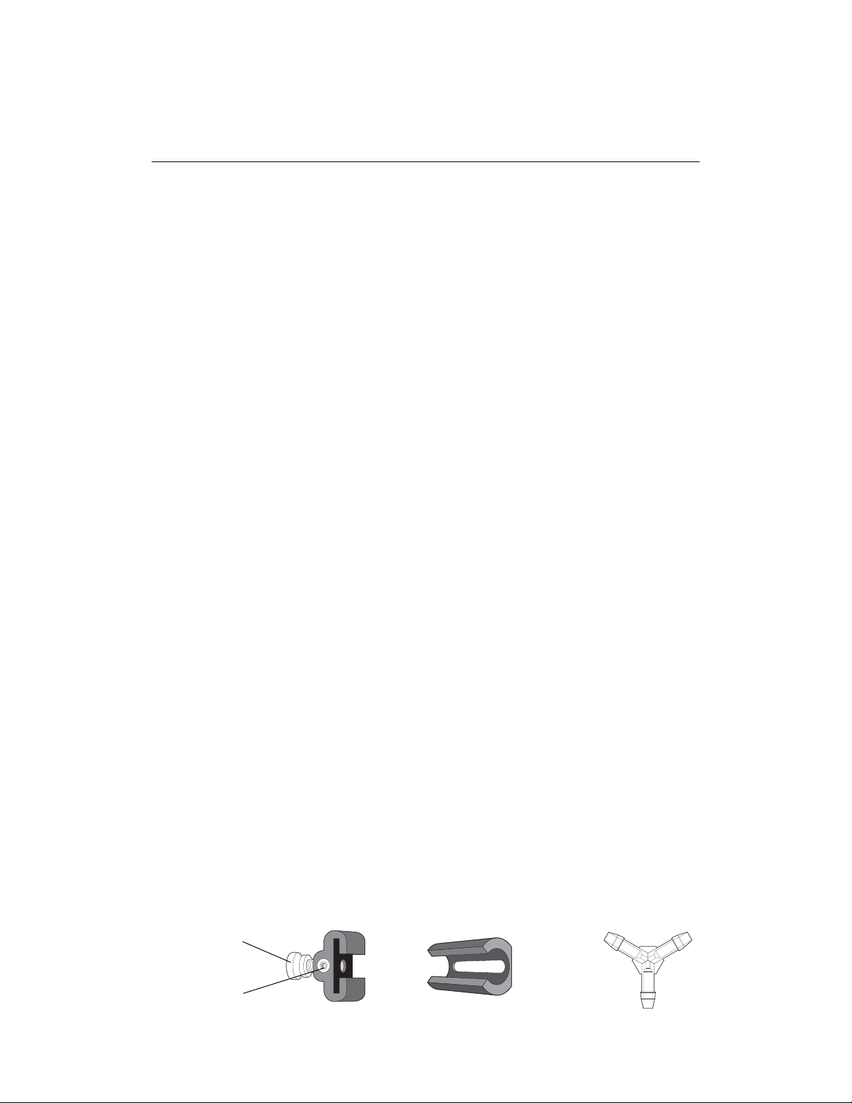
Plunger Caps/ There are two plunger caps, one for each syringe. The
Plunger Cap Screw plunger caps fit both the 10 and 30 ml syringes (Figure 3.11).
Lever Attachment Screw The lever attachment screw is on the plunger cap. This
screw fits into the groove of the lever and conducts the driving
force of the cam in dispensing the gel solution.
Syringe Sleeve One pair of syringe sleeves for each size syringe is
provided (Figure 3.12). The sleeve is a movable adaptor to
mount the syringe in the holder. The sleeve should conform to
the syringe. If the syringe is too tight or too loose, adjust the
sleeve by pushing or pulling.
Syringe Holder/ The syringe holder is next to the lever. It holds the syringe
Syringe Holder Screw in place and controls the delivery volume. The syringe is held
in the holder by tightening the holder screw against the sleeve.
Volume Adjustment Screw The volume adjustment screw is on both sides of the syringe
holder (Figure 3.10). It adjusts the holder to the desired delivery
volume.
Volume Setting Indicator The volume setting indicator is at the top corner of the syringe
holder nearest the volume setting numbers (Figure 3.10).
Lever The position of the lever is controlled by the rotation of the
cam (Figure 3.10). The lever must be in the vertical or start
position before use.
Tygon Tubing One length of Tygon™tubing is provided. Cut the tubing into two
15.5 cm and one 9 cm lengths. The longer pieces are used to
transport the gel solution from the syringes into the Y-fitting. The
short piece will transport the gel solution from the Y-fitting to
the gel sandwich.
Y-Fitting The Y-fitting mixes the high and low density gel
solutions (Figure 3.13).
Luer Fitting/Coupling There are two luer fittings that fit both 10 and 30 ml syringes.
The fittings twist onto the syringe and connect to the Tygon
tubing on the other end. A luer coupling is used on one end
of the 9 cm tubing to connect it to the gel sandwich stopcock.
10
Fig. 3.11. Plunger Cap Fig. 3.12. Syringe sleeve Fig. 3.13. Y-Fitting
Lever
attachment
screw
Plunger cap
screw
Page 15

Section 4
Denaturing Gel Electrophoresis (DGGE, CDGE, TTGE)
4.1 Introduction to Denaturing Gradient Gel Electrophoresis (DGGE)
Denaturing Gradient Gel Electrophoresis (DGGE) is an electrophoretic method to identify
single base changes in a segment of DNA. Separation techniques on which DGGE is based were
first described by Fischer and Lerman.
2
In a denaturing gradient acrylamide gel,
double-stranded DNA is subjected to an increasing denaturant environment and will melt in
discrete segments called "melting domains". The melting temperature (Tm) of these domains is
sequence-specific. When the Tmof the lowest melting domain is reached, the DNA will become
partially melted, creating branched molecules. Partial melting of the DNA reduces its mobility in
a polyacrylamide gel. Since the Tmof a particular melting domain is sequence-specific, the
presence of a mutation will alter the melting profile of that DNA when compared to wild-type. DNA
containing mutations will encounter mobility shifts at different positions in the gel than the
wild-type. If the fragment completely denatures, then migration again becomes a function of
size (Figure 4.1).
Fig. 4.1. An example of DNA melting properties in a perpendicular denaturing gradient gel. At a low concentration of denaturant, the DNA fragment remains double-stranded, but as the concentration of denaturant increases,
the DNA fragment begins to melt. Then, at very high concentrations of denaturant, the DNA fragment can completely
melt, creating two single strands.
In DGGE, the denaturing environment is created by a combination of uniform temperature,
typically between 50 and 65 °C and a linear denaturant gradient formed with urea and
formamide. A solution of 100% chemical denaturant consists of 7 M urea and 40% formamide.
The denaturing gradient may be formed perpendicular or parallel to the direction of
electrophoresis. A perpendicular gradient gel, in which the gradient is perpendicular to the
electric field, typically uses a broad denaturing gradient range, such as 0–100% or 20–70%.
2
In parallel DGGE, the denaturing gradient is parallel to the electric field, and the range of
denaturant is narrowed to allow better separation of fragments.9Examples of perpendicular
and parallel denaturing gradient gels with homoduplex and heteroduplex fragments are shown
in Figure 4.2.
11
Double strand
Single strands
Denaturant
Wild Type
Mutant
100%0%
Partially melted
"wild type"
Partially melted
"mutant"
Electrophoresis
Denaturant
0%
*
Partially melted
“mutant”
Partially melted
“wild type”
100%
Electrophoresis
Single strands
Wild Type
*
Mutant
Double strand
Page 16

Fig. 4.2. A. Perpendicular denaturing gradient gel in which the denaturing gradient is perpendicular to the
electrophoresis direction. Mutant and wild-type alleles of exon 6 from the TP53 gene amplified from primary breast
carcinomas and separated by perpendicular DGGE (0–70% denaturant) run at 80 V for 2 hours at 56 °C. The first two
bands on the left are heteroduplexes and the other two bands are the homoduplexes. B. Parallel denaturing gradient
gel in which the denaturing gradient is parallel to the electrophoresis direction. Mutant and wild-type alleles of
exon 8 from the p53 gene separated by an 8% acrylamide:bis (37.5:1) gel with a parallel gradient of 40–65% denaturant.
The gel was run at 150 V for 2.5 hours at 60 °C in 1x TAE buffer. Lane 1 contains the mutant fragment, lane 2 contains the
wild-type fragment, lane 3 contains both the mutant and wild-type fragments.
When running a denaturing gradient gel, both the mutant and wild-type DNA fragments are
run on the same gel. This way, mutations are detected by differential migration of mutant and
wild-type DNA. The mutant and wild-type fragments are typically amplified by the polymerase
chain reaction (PCR) to make enough DNA to load on the gel. Optimal resolution is attained
when the molecules do not completely denature and the region screened is in the lowest
melting domain. The addition of a 30–40 base pair GC clamp to one of the PCR primers insures
that the region screened is in the lower melting domain and that the DNA will remain partially
double-stranded.34An alternative to GC clamps is using psoralen derivative PCR primers called
ChemiClamp primers.10Because ChemiClamps covalently link the two DNA strands at one
end, they should not be used when isolating a DNA fragment which is going to be sequenced
from a gel. The size of the DNA fragments run on a denaturing gel can be as large as 1 kb in
length, but only the lower melting domains will be available for mutation analysis. For complete
analysis of fragments over 1 kb in length, more than one PCR reaction should be performed.
11
The thermodynamics of the transition of double-stranded to single-stranded DNA have been
described by a computer program developed by Lerman.12Bio-Rad offers a Macintosh
®
computer program, MacMelt™software, which calculates and graphs theoretical DNA melting
profiles. Melting profile programs can show regions of theoretical high and low melting domains
of a known sequence. Placement of primers and GC clamps can be optimized by analysis of
placement effect on the DNA melting profile.
The method of creating heteroduplex molecules helps in detecting homoduplex mutations.
This process is typically done when it is not originally possible to resolve a homoduplex
mutation. Analysis of heteroduplex molecules can, therefore, increase the sensitivity of DGGE.
Heteroduplexes can be formed by adding the wild-type and mutant template DNAs in the same
PCR reaction or by adding separate PCR products together, then denaturing and
allowing them to re-anneal. A heteroduplex has a mismatch in the double-strand causing a
distortion in its usual conformation; this has a destabilizing effect and causes the DNA strands
to denature at a lower concentration of denaturant (Figure 4.3). The heteroduplex bands always
migrate more slowly than the corresponding homoduplex bands under specific conditions.
12
AB
0%
40%
70%
65%
Page 17

Fig. 4.3. An example of wild-type and mutant DNA fragments that were denatured and re-annealed to
generate four fragments: two heteroduplexes and two homoduplexes run on a parallel
denaturing gradient gel. The melting behavior of the heteroduplexes is altered so that they melt at a lower denaturant
concentration than the homoduplexes and can be visualized on a denaturing gradient gel.
Reagent Preparation
The concentration of denaturant to use varies for the sample being analyzed with the
DCode system. Typically a broad denaturing gradient range is used, such as 0–100% or
20–70%. The concentration of acrylamide can also vary, depending on the size of the
fragment analyzed. Both 0% and 100% denaturant should be made as stock solutions. A
100% denaturant is a mixture of 7 M urea and 40% deionized formamide. Reagents for
casting and running a DGGE gel are included in the DCode Electrophoresis Reagent Kit for
DGGE/CDGE, catalog number 170-9032.
For different percent crosslinking, use the equation below to determine the amount of Bis
to add. The example stock solution below is for an acrylamide/bis ratio of 37.5:1.
40% Acrylamide/Bis (37.5:1)
Reagent Amount
Acrylamide 38.93 g
Bis-acrylamide 1.07 g
dH2O to 100.0 ml
Filter through a 0.45 µ filter and store at 4°C.
13
Wild Type DNA Mutant DNA
Wild-Type DNA
Mutant DNA
wt + mut
wt
20%
60%
mut
Heteroduplex
DNA
Homoduplex
DNA
Homoduplexes
Heteroduplexes
Denature and reanneal
Denaturant
Denature and reanneal
Homoduplex
DNA
wt mut wt + mut
Heteroduplex
DNA
Heteroduplexes
Homoduplexes
Page 18

Polyacrylamide gels are described by reference to two characteristics:
1) The total monomer concentration (%T)
2) The crosslinking monomer concentration (%C)
%T =
gm acrylamide + gm bis-acrylamide
x 100
Total Volume
%C =
gm bis-acrylamide
x 100
gm acrylamide + gm bis-acrylamide
50x TAE Buffer
Reagent Amount Final Concentration
Tris base 242.0 g 2 M
Acetic acid, glacial 57.1 ml 1 M
0.5 M EDTA, pH 8.0 100.0 ml 50 mM
dH2O to 1,000.0 ml
Mix. Autoclave for 20–30 minutes. Store at room temperature.
The table below provides the percentage acrylamide/bis needed for a particular size range.
Gel Percentage Base Pair Separation
6% 300–1000 bp
8% 200–400 bp
10% 100–300 bp
0% Denaturing Solution
6% Gel 8% Gel 10% Gel
12% Gel
40% Acrylamide/Bis 15 ml 20 ml 25 ml 30 ml
50x TAE buffer 2 ml 2 ml 2 ml 2 ml
dH2O 83 ml 78 ml 73 ml 68 ml
Total volume 100 ml 100 ml 100 ml 100 ml
Degas for 10–15 minutes. Filter through a 0.45 µ filter. Store at 4°C in a brown bottle for
approximately 1 month.
100% Denaturing Solution
6% Gel 8% Gel
10% Gel 12% Gel
40% Acrylamide/Bis 15 ml 20 ml 25 ml 30 ml
50x TAE buffer 2 ml 2 ml 2 ml 2 ml
Formamide (deionized) 40 ml 40 ml 40 ml 40 ml
Urea 42 g 42 g 42 g 42 g
dH2O to 100 ml to 100 ml to 100 ml to 100 ml
Degas for 10–15 minutes. Filter through a 0.45 µ filter. Store at 4°C in a brown bottle for
approximately 1 month. A 100% denaturant solution requires re-dissolving after storage. Place
the bottle in a warm bath and stir for faster results.
14
Page 19

For denaturing solutions less than 100%, use the volumes for acrylamide, TAE and water
described above in the 100% Denaturing Solution. Use the amounts indicated below for urea
and formamide.
Denaturing Solution 10% 20% 30% 40% 50% 60% 70% 80% 90%
Formamide (ml) 4 8 12 16 20 24 28 32 36
Urea (g) 4.2 8.4 12.6 16.8 21 25.2 29.4 33.6 37.8
10% Ammonium Persulfate
Reagent Amount
Ammonium persulfate 0.1 g
dH2O 1.0 ml
Store at –20°C for about a week.
DCode Dye Solution
Reagent Amount Final
Concentration
Bromophenol blue 0.05 g 0.5%
Xylene cyanol 0.05 g 0.5%
1x TAE buffer 10.0 ml 1x
Store at room temperature. This reagent is supplied in the DCode electrophoresis reagent
kit for DGGE, CDGE.
2x Gel Loading Dye
Reagent Amount Final
Concentration
2% Bromophenol blue 0.25 ml 0.05%
2% Xylene cyanol 0.25 ml
0.05%
100% Glycerol 7.0 ml
70%
dH2O 2.5 ml
Total volume 10.0 ml
Store at room temperature.
1x TAE Running Buffer
Reagent Amount
50x TAE buffer 140 ml
dH2O 6,860 ml
Total volume 7,000 ml
Gel Volumes
Linear Denaturing Gradient Gels
The table below provides the required gradient delivery system setting per gel size desired.
The volume per syringe is for the amount required for each low and high density syringe, and
the volume adjustment setting sets the gradient delivery system for the proper delivery of
solutions. The 7.5 x 10 cm and 16 x 16 cm size gels are recommended for the perpendicular gel
formats, whereas the 16 x 10 cm and 16 x 16 cm gel formats are recommended for parallel
denaturing gels. The volume per syringe requires a larger volume of reagent than the volume
setting indicates, because the excess volume in the syringe is needed to push the correct amount
of gel solution into the gel sandwich.
15
Page 20

Volume Volume
per Adjustment
Spacer Size Gel Size Syringe Setting
0.75 mm 7.5 x 10 cm 5 ml 3.5
16 x 10 cm 8 ml 6.5
16 x 16 cm 11 ml 9.5
1.00 mm 7.5 x 10 cm 6 ml 4.5
16 x 10 cm 11 ml 9.5
16 x 16 cm 16 ml 14.5
1.50 mm 7.5 x 10 cm 8 ml 6.5
16 x 10 cm 15 ml 13.5
16 x 16 cm 24 ml 22.5
Spacer Thickness 16 x 16 cm Gel 16 x 10 cm Gel
0.75 mm 25 ml 15 ml
1.00 mm 30 ml 20 ml
1.50 mm 45 ml 26 ml
Sample Preparation
1. It is important to optimize the PCR reaction to minimize unwanted products which may
interfere with gel analysis. PCR products should be evaluated for purity by agarose gel
electrophoresis before being loaded onto a denaturing acrylamide gel.
2. For a perpendicular denaturing gel, load about 1–3 µg of amplified DNA per well
(usually 50% of a 100 µl PCR volume from a 100 ng DNA template). Both wild-type and
mutant samples are mixed together and run on the same gel.
3. For a parallel denaturing gel, load 180–300 ng of amplified DNA per well (usually 5–10%
of a 100 µl PCR volume from a 100 ng DNA template). A wild-type control should be run
on every gel.
4. Add an equal volume of 2x gel loading dye to the sample.
5. Heteroduplexes can be generated during PCR by amplifying the mutant and wild-type samples
in the same tube. If the samples are amplified in separate tubes, then heteroduplexes can be
formed by mixing an equal amount of mutant and wild-type samples in one tube. Heat the tube
at 95 °C for 5 minutes, then place at 65°C for 1 hour, and let slowly cool to room temperature.
16
Page 21
Temperature Controller
The temperature controller maintains the desired buffer temperature in the DCode system.
Turning on the Controller
Turn the controller on by pressing the power button and wait for the controller to
initialize. The controller will display the following screens in order:
• The program code
• The date code and serial code
• The hours used
• The temperature control screen (see Fig. 1).
The controller is now ready to be
programmed.
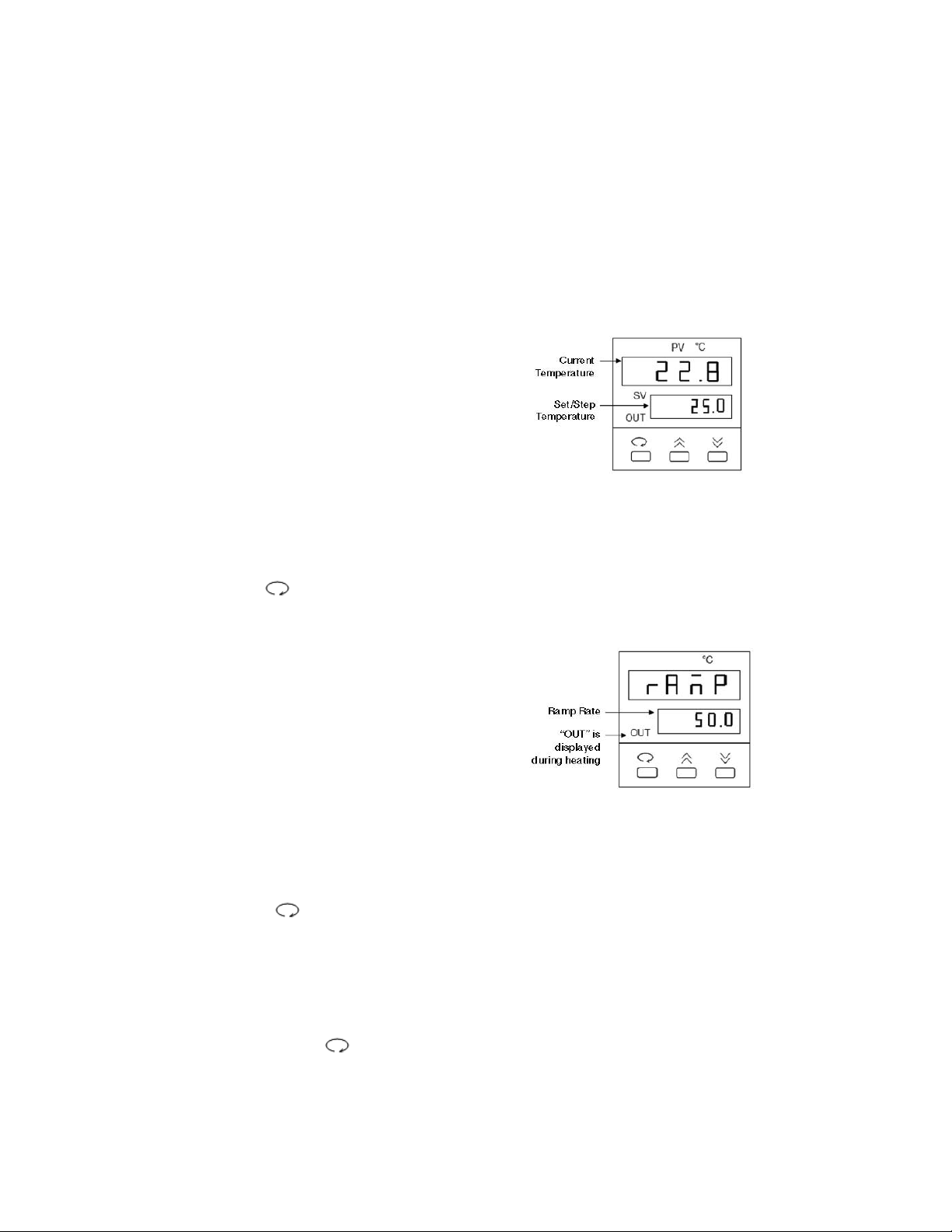
Setting the Set Temperature and Ramp Rate
1. From the temperature control screen,
use the arrow keys to adjust the Set
Temperature to your desired target
temperature in °C (Fig. 1)
2. Use the key to display the ramp
control screen. (Fig. 2.)
3. From the ramp control screen, use
the arrow keys to set the desired
temperature Ramp Rate in °C per hour.
Note that the maximum ramp rate for
the DCode is 50°C /hr. If the target
Ramp Rate is set using the controller
to higher than 50°C /hr the maximum
ramp rate of 50°C /hr will be used.
4. To toggle between the temperature control
screen and the ramp control screen, or to
review the set temperature and ramp rate,
press the key at any time
Note: Following programming by default the controller displays the Step Temperature rather
than the Set Temperature (see Fig 1. below). The step temperature is the next temperature
value the system will reach as it heats/cools to reach set temperature. To display the Set
Temperature press the key.
17
Fig. 1. Temperature Control Screen.
Fig. 2. Ramp Control Screen.
Page 22
Pre-heating the Running Buffer
1. Fill the electrophoresis tank with 7 L of 1x TAE running buffer.
Note: It is recommended that the running buffer not be reused. Reusing the running buffer
may affect the migration rate and band resolution.
2. Place the temperature control module on top of the electrophoresis tank. Attach the power
cord to the temperature control module and turn the power, pump, and heater on. The
clear loading lid should be on the temperature control module during preheating.
3. Set the temperature controller to the desired temperature. Set the temperature ramp rate
to 200 °C/hr to allow the buffer to reach the desired temperature the quickest.
4. Preheat the buffer to the set temperature. It can take 1 to 1.5 hours for the system to heat
the buffer up to the set temperature. Heating the buffer in a microwave helps reduce the
preheating time.
Assembling the Perpendicular Gradient Gel Sandwich
For perpendicular gel formats, 7.5 x 10 cm (dual) and 16 x 16 cm (single) gel sandwich sizes
are recommended. These two different perpendicular gel formats consist of a set of spacers that
provide casting at the side of the gel sandwich via the stopcock. To insure proper alignment,
make sure all plates and spacers are clean and dry before assembly. Use caution when
assembling the glass plate sandwiches. Wear gloves and eye protection at all times.
1. Assemble the gel sandwich on a clean surface. Lay the large rectangular plate down first,
then place the left and right spacers of equal thickness along the short edges of the larger
rectangular plate. To assemble perpendicular gradient gels, place the spacers so that the
holes on the spacers are at the top of the plate with the grooved side of the spacer against
the larger glass plate. When properly placed, the notched edges of the spacers will face
each another.
2. Place a short glass plate on top of the spacers so that it is flush with the bottom edge of
the long plate.
3. Loosen the single screw of each sandwich clamp by turning counterclockwise. Place each
clamp by the appropriate side of the gel sandwich with the locating arrows facing up and
toward the glass plates (Figure 4.5).
Fig. 4.5. Positioning glass plates, spacers, and clamps.
18
Page 23
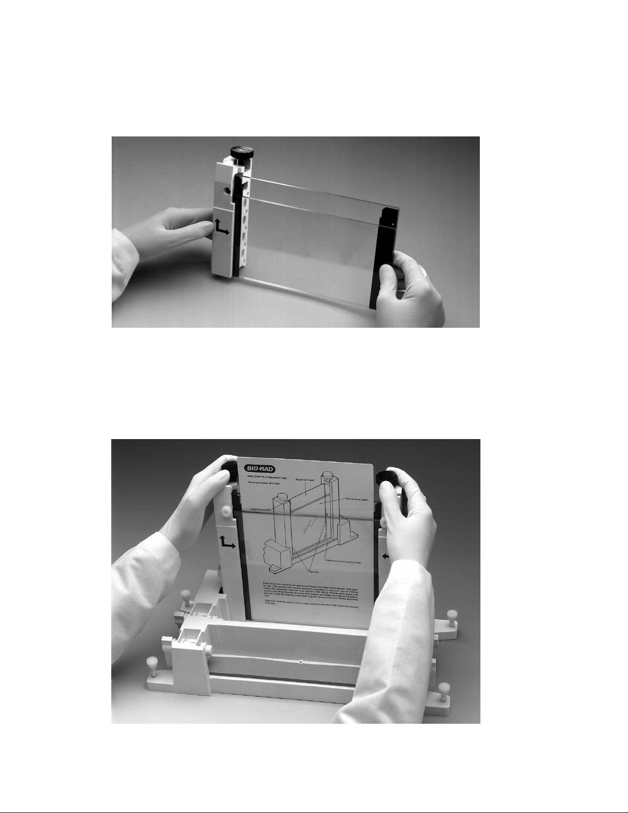
4. Grasp the gel sandwich firmly. Guide the left and right clamps onto the sandwich so
that the long and short plates fit the appropriate notches in the clamp (Figure 4.6). Tighten
the screws enough to hold the plates in place.
Fig. 4.6. Attaching the clamps to the glass plate assembly.
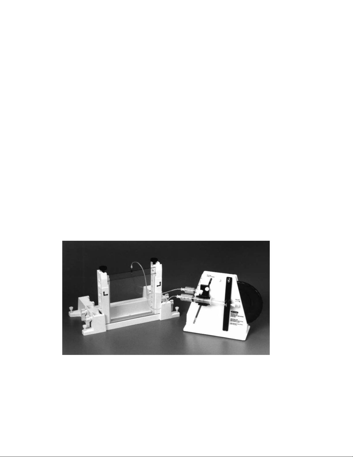
5. Place the sandwich assembly in the alignment slot (the slot without cams) of the casting
stand with the short glass plate forward (Figure 4.7). Loosen the sandwich clamps and
insert an alignment card to keep the spacers parallel to the clamps.
Note: Always use the alignment slot and alignment card to set the spacers in place. Failure
to use these can result in gel leakage when casting, as well as buffer leakage during the
run.
Fig. 4.7. Aligning spacers in the sandwich assembly.
19
Page 24

6. Align the plates and spacers by simultaneously pushing inward on both clamps at the
locating arrows while, at the same time, pushing down on the spacers with your thumbs.
Tighten both clamps just enough to hold the sandwich in place. Pushing inward on both
clamps at the locating arrows will insure that the spacers and glass plates are flush against
the sides of the clamps (Figure 4.7).
7. Remove the alignment card. Then, remove the sandwich assembly from the casting stand
and check that the plates and spacers are flush at the bottom. If they are not flush, realign
the sandwich and spacers (Repeat steps 5–7).
8. When a good alignment and seal are obtained, tighten the clamp screws until it is finger-tight.
9. Place the proper comb in the sandwich and align it against the notches in the spacers. For
the 7.5 x 10 cm perpendicular gradient gel, insert the middle spacer into the center of the
sandwich until it fits into the middle notch on the comb. Straighten the spacer and the comb.
The bottom of the middle spacer should also be flush against the glass plates (Figure 4.8).
Note: The proper comb for a 7.5 x 10 cm gel is the dual comb that requires a middle
spacer to separate the two 7.5 x 10 cm gels, whereas the 16 x 16 cm gel comb is a
single comb that does not require a middle spacer.
Fig. 4.8. Positioning the middle spacer in a 7.5 x 10 cm gel sandwich assembly.
10. Inspect the comb gasket to insure that the comb gasket is free of gel material. Remove
any polymerized material in the comb gasket vent ports. The soft comb gasket should
lay flat within the comb gasket holder.
Note: To remove the soft comb gasket from the holder, push the gasket away from the
four holes in the holder. To replace the comb gasket, insert the gasket into the holder
with the thick portion in first. Place one corner of the gasket against the top portion of the
holder. With a flat spatula, guide the four tabs into the four holes. Carefully run the
spatula across the gasket to completely set the gasket in place.
20
Page 25

11. Stand the sandwich assembly upright on a flat surface. Loosen the comb gasket holder
screws until the threads can no longer be seen. Mark an arrow on the middle of the screw head
using a permanent marker (this will be the marker for adjusting the proper screw tension). With
the comb gasket screws and the long plate facing you, slide the comb gasket holder down over
the top of the assembled glass sandwich. When the comb gasket is properly placed, the
angled cuts on the edges of the comb gasket will rest on the complementary angled cuts at
the top of each spacer. Turn the screws until they just make contact with the glass plate, then
twist the screws an additional 1/4 turn.
12. Before the screws can be completely tightened, the pressure clamp must be attached to the
sandwich assembly. Loosen the pressure clamp screw. Mark an arrow on the middle of the
screw head using a permanent marker (this will be the marker for adjusting the proper screw
tension). Lay the pressure clamp on a flat surface so that the notched cut-out faces the
ceiling and the pressure clamp screw points up and away from you.
13. Without touching the comb gasket holder, turn the assembled glass sandwich so that the comb
gasket screws are facing down and the vent ports are facing up. Center the assembly over the
pressure clamp and allow the assembly to rest on top of it. A properly placed pressure clamp
will be situated on the middle of the sandwich with the notched cut-out against the bottom of
the glass plate. Proper placement of the sandwich assembly in the pressure clamp will insure
that equal force is applied to the comb gasket holder during the final tightening of the screws.
Twist the pressure clamp screw until it makes contact with the comb gasket holder, then
tighten the pressure clamp screw two additional turns (use the arrow to keep track of the turns).
Note: Check to insure that the bottom of the glass plates are still flush. If the plates are
off-set, one or both of the sandwich clamps may not be tightened. Repeat steps 5–13.
14. Tighten the comb gasket screws an additional one turn. If it is tightened more, the
glass plates may crack. For a proper seal, check to see that the notches on both the
comb gasket and spacers are sealed against each other. It is important that the gasket
is placed properly to prevent leakage while casting. Remove the pressure clamp.
15. Twist the injection port fitting into the holes on the sandwich clamps. Do not over-tighten; it will
damage the O-ring and cause leakage. A snug fit is all that is needed to place the injection
port against the glass plate assembly. Push a stopcock into each of the injection port fittings.
Make sure that the fit is snug. A loose stopcock may cause leakage during casting.
16. Place the gray sponge onto the front casting slot. The camshafts on the casting stand should
have the handles pointing up and pulled out. Place the sandwich on the sponge with the shorter
plate facing forward. When the sandwich is placed correctly, press down on the sandwich and
turn the handles of the camshaft down so that the cams lock the sandwich in place.
a. For a 7.5 x 10 cm dual gel sandwich, only half of the sandwich is cast at a time. Open
the stopcock and unplug the vent port on the side of the sandwich where the gel is
being cast. To prevent leakage the other half of the sandwich should have a closed
stopcock and plugged vent port.
b. For a 16 x 16 cm gel sandwich, both vent ports should be plugged to prevent leakage
during casting. The 16 x 16 cm spacers are one orientation only, thus the special
casting groove is always on the right-hand side and the smaller, shorter groove on the
left-hand side of the gel sandwich.
17. Tilt the gel sandwich assembly and casting stand using the tilt rod as a leg. Adjust the tilt
level to the highest etched line on the rod (the one farthest from the black tilt-rod cap) for
the 7.5 x 10 cm format and the lowest etched line on the rod for the 16 x 16 cm format.
18. Familiarize yourself with the Model 475 Gradient Delivery System before casting
perpendicular gradient gels.
21
Page 26

Casting Perpendicular Denaturing Gradient Gels
1. One length of Tygon tubing is provided and should be cut into two 15.5 cm lengths and one
9 cm length. The longer pieces of Tygon tubing will be used to conduct the gel solution
from the syringes into the Y-fitting. The short piece of Tygon tubing will conduct the gel
solution from the Y-fitting to the gel sandwich. Connect one end of the 9 cm Tygon tubing
to the Y-fitting and connect a luer coupling to the other end of the 9 cm tubing. Connect luer
fittings onto the two long pieces of tubing. Connect the luer fittings to 10 ml or 30 ml syringes.
Do not connect the long Tygon tubing to the Y-fitting at this time.
2. Label one of the syringes LO (for the low density solution) and one HI (for the high density
solution). Attach a plunger cap onto each syringe plunger “head.” Position the plunger "head"
in the middle of the plunger cap and tighten enough to hold the plunger in place. Position the
cap in the middle for proper alignment with the lever on the gradient delivery system. Slide
each syringe into a syringe sleeve. Move the sleeve to the middle of the syringe, keeping the
volume gradations visible. Make sure that the lever attachment screw is in the same plane
as the flat or back side of the sleeve. This is very important for proper attachment of the
syringe to the lever.
Note: Insure that the tubing is free of any gel material by pushing water through the tubing with
the syringe. The tubing should be free of material before casting, remove any remaining water
from the tubing.
3. Rotate the cam wheel counterclockwise to the vertical or start position. To set the desired
delivery volume, loosen the volume adjustment screw. Place the volume setting indicator
located on the syringe holder to the desired volume setting. Tighten the volume adjustment
screw. For 7.5 x 10 cm gels (1 mm thick), set the volume setting indicator to 4.5. For
16 x 16 cm gels (1 mm thick), set the volume setting indicator to 14.5. Refer to Section 4.1.
4. From the stocks solutions, pipet out the desired amounts of the high and low density gel
solutions into two disposable test tubes, Section 4.1.
Optional: To visually check the formation of the gradient, add 100 µl of DCode dye
solution per 5 ml high density solution.
Note: The gel solution volume should be greater than the amount set on the volume
adjustment lever. For example, if the setting indicator is set at 4.5, the syringe should
contain 5 ml of the gel solution. This extra solution is needed to push the correct amount
into the gel sandwich.
The steps below are time-sensitive (about 7–10 minutes). Insure that steps 1 through
4 are done before proceeding further. Be thoroughly familiar with the following steps
before casting the gel.
5. Add a final concentration of 0.09% (v/v) each of ammonium persulfate and TEMED
solutions. The 0.09% (v/v) concentrations allow about 5–7 minutes to finish casting the gel
before polymerization. Cap and mix by inverting several times. With the syringe connected
to the tubing, withdraw all of the high density solution into the HI syringe. Do the same for
the low density solution into the LO syringe.
Note: Acrylamide is a very hazardous substance. Use caution: wear gloves and eye
protection at all times. Avoid skin contact.
6. Carefully remove air bubbles from the LO syringe by turning it upside down (plunger cap
towards the bench) and gently tapping. Push the gel solution to the end of the tubing. Do
not push it out of the tubing as loss of gel solution will disturb the volume required to cast
the desired gel.
22
Page 27

7. Place the LO syringe into the gradient delivery system syringe holder (LO density side) by
holding the syringe by the plunger and inserting the lever attachment screw into the lever
groove. Do not handle the syringe. It will dispense the gel solution out of the syringe.
Casting a perpendicular gel is referred to as a bottom filling method, so place the LO
syringe on the correct side of the gradient system.
8. Carefully remove the air bubbles from the HI syringe by turning it upside down (plunger
cap towards the bench) and gently tapping. Push the gel solution to the end of the tubing.
Do not push it out of the tubing as loss of gel solution will disturb the volume required to
cast the desired gel.
9. Place the HI syringe into the gradient delivery system syringe holder (HI density side) by
holding the syringe by the plunger and inserting the lever attachment screw into the lever
groove. Do not handle the syringe. It will dispense the gel solution out of the syringe.
10. Slide the tubing from the low density syringe to one end of the Y-fitting. Do the same for
the high density syringe.
11. Connect the 9 cm tubing with the luer coupling on the sandwich assembly stopcock. Insure
that the stopcock is open and that the vent port is unplugged for the half of the sandwich
being cast.
Note: For a 16 x 16 cm single gel, both stopcocks are open during casting. After casting,
both stopcocks are closed.
12. Rotate the cam wheel slowly and steadily to deliver the gel solution. It is important to cast the
gel solution at a steady pace to avoid disturbances between gel solutions within the sandwich.
Fig. 4.9. Casting a perpendicular gradient gel using the Model 475 gradient delivery system.
13. Plug the vent port and close the stopcock on the gel sandwich when the cam wheel has
reached the stop position. Carefully level the gel sandwich by adjusting the gasket tilt rod.
Be sure to loosen the tilt rod screw and not the sandwich clamp screw.
Note: For a properly cast perpendicular gradient gel it is extremely important to level the
sandwich assembly after casting.
23
Page 28

14. Immediately remove the tubing from the sandwich assembly stopcock. Place the tubing into
a beaker of water and reverse the cam on the Gradient Delivery System. This will rinse the
tubing and Y-fitting. Remove both syringes from the syringe holder on the gradient delivery
system. Detach the syringe tubing from the Y-fitting. Run or push water out through the
syringe, tubing and Y-fitting several times to get rid of any residual gel solution. It is extremely
important that this is done quickly after casting to avoid any gel polymerization.
15. Let the gel polymerize for about 60 minutes. To cast the other half of the 7.5 x 10 cm gel
format, remove the gasket tilt rod and place it on the other side of the comb gasket. Repeat
steps 4 through 15.
Note: If casting a single 7.5 x 10 cm gel, let the gel solution polymerize for 60 minutes. Carefully
remove the comb gasket; leave the comb in place and pipette (on an opening near the
spacer) a 10 ml gel solution plus initiators in the uncast half of the sandwich to create a dam.
16. After polymerization, remove the comb by pulling it straight up slowly and gently.
17. Continue with Section 8 for electrophoresis.
Assembling the Parallel Gradient Gel Sandwich
For parallel gel formats, a 16 x 16 cm gel sandwich size is recommended. The parallel gel
format does not require special casting grooves in the spacers, so the straight edge portion
(ungrooved side) of the spacers is used. To insure proper alignment, make sure all plates
and spacers are clean and dry before assembly. Use caution when assembling the glass
plate sandwiches. Wear gloves and eye protection at all times.
1. Assemble the gel sandwich on a clean surface. Lay the large rectangular plate down first, then
place the left and right spacers of equal thickness along the short edges of the larger
rectangular plate. To assemble parallel gradient gels, place the spacers so that the grooved
opening of the spacers face the sandwich clamps. When properly placed, the grooved side of
the spacers and the notches will face the sandwich clamps, and the hole is located near the
top of the plates.
2. Place the short glass plate on top of the spacers so that it is flush with the bottom edge
of the long plate.
3. Loosen the single screw of each sandwich clamp by turning each screw counterclockwise.
Place each clamp by the appropriate side of the gel sandwich with the locating arrows
facing up and toward the glass plates (Figure 4.10).
Fig. 4.10. Positioning glass plates, spacers, and clamps.
24
Page 29

4. Grasp the gel sandwich firmly. Guide the left and right clamps onto the sandwich so that
the long and short plates fit the appropriate notches in the clamp. Tighten the screws
enough to hold the plates in place (Figure 4.11).
Fig. 4.11. Attaching the clamps to the glass plate assembly.
5. Place the sandwich assembly in the alignment slot (the slot without cams) of the casting
stand with the short glass plate forward (Figure 4.12). Loosen the sandwich clamps and
insert an alignment card to keep the spacers parallel to the clamps.
Note: Always use the alignment slot and alignment card to set the spacers in place. Failure
to use these can result in gel leakage while casting, as well as buffer leakage during the
run.
6. Align the plates and spacers by simultaneously pushing inward on both clamps at the
locating arrows while at the same time pushing down on the spacers with your thumbs;
tighten both clamps just enough to hold the sandwich in place. Pushing inward on both
clamps at the locating arrows will insure that the spacers and glass plates are flush against
the sides of the clamps (Figure 4.12).
Fig. 4.12. Aligning spacers in the sandwich assembly.
25
Page 30

7. Remove the alignment card. Remove the sandwich assembly from the casting stand and
check that the plates and spacers are flush at the bottom. If the spacers and glass plates
are not flush, realign the sandwich and spacers to obtain a good seal (Repeat steps 5–7).
8. When a good alignment and seal are obtained, tighten the clamp screws until it is finger-tight.
Casting Parallel Denaturing Gradient Gels
1. Place the gray sponge onto the front casting slot. The camshafts on the casting stand should
have the handles pointing up and pulled out. Place the sandwich assembly on the sponge
with the shorter plate facing you. When the sandwich is placed correctly, press down on
the sandwich and turn the handles of the camshaft down so that the cams lock the sandwich
in place. Position the gel sandwich assembly by standing it upright.
2. One length of Tygon tubing is provided and should be cut into two 15.5 cm lengths and one
9 cm length. The longer pieces of Tygon tubing will be used to conduct the gel
solution from the syringes into the Y-fitting. The short piece of Tygon tubing will conduct the
gel solution from the Y-fitting to the gel sandwich. Connect one end of the 9 cm Tygon
tubing to the Y-fitting and connect a luer coupling to the other end of the 9 cm tubing. Connect
luer fittings onto the two long pieces of tubing. Connect the luer fittings to 30 ml syringes. Do
not connect the long Tygon tubing to the Y-fitting at this time.
3. Label one of the syringes LO (for the low density solution) and one HI (for the high
density solution). Attach a plunger cap onto each syringe plunger “head.” Position the
plunger "head" in the middle of the plunger cap and tighten enough to hold the plunger
in place. Position the cap in the middle for proper alignment with the lever on the
gradient delivery system. Slide each syringe into a syringe sleeve. Move the sleeve to
the middle of the syringe, keeping the volume gradations visible. Make sure that the lever
attachment screw is in the same plane as the flat or back side of the sleeve. This is very
important for proper attachment of the syringe to the lever.
Note: Insure that the tubing is free of any gel material by pushing water through the
tubing with the syringe. The tubing should be free of material before casting, remove any
remaining water from the tubing.
4. Rotate the cam wheel counterclockwise to the vertical or start position. To set the desired
delivery volume, loosen the volume adjustment screw. Place the volume setting indicator
located on the syringe holder to the desired volume setting. Tighten the volume adjustment
screw. For 16 x 16 cm gels (1 mm thick), set the volume setting indicator to 14.5. Refer to
Section 4.1.
5. From the stocks solutions, pipet out the desired amounts of the high and low density gel
solutions into two disposable test tubes (refer to the Section 4.1).
Optional: To visually check the formation of the gradient, add 100 µl of DCode dye
solution per 5 ml high density solution.
The steps below are time-sensitive (about 7–10 minutes). Insure that steps 2
through 5 are done before proceeding further. Be thoroughly familiar with the
following steps before casting the gel.
6. Add the final concentration of 0.09% (v/v) each of ammonium persulfate and TEMED
solutions. The 0.09% (v/v) concentrations allow about 5–7 minutes to finish casting the gel
before polymerization. Cap and mix by inverting several times. With the syringe connected
to the tubing, withdraw all of the high density solution into the HI syringe. Do the same for
the low density solution into the LO syringe.
Note: Acrylamide is a very hazardous substance. Use caution: wear gloves and eye
protection at all times. Avoid skin contact.
26
Page 31
7. Carefully remove air bubbles from the LO syringe by turning the syringe upside down
(plunger cap towards the bench) and gently tapping the syringe. Push the gel solution to
the end of the tubing. Do not push it out of the tubing as loss of solution will disturb the
volume required to cast the desired gel.
Note: The gel solution volume should be greater than the amount set on the volume adjustment
lever. For example, if the indicator setting is set at 14.5, the syringe should contain 15 ml of
solution. This extra solution is needed to deliver the correct amount for casting.
8. Place the LO syringe into the gradient delivery system syringe holder (LO density side) by
holding the syringe by the plunger and inserting the lever attachment screw into the lever
groove. Do not handle the syringe. It will dispense the gel solution out of the syringe. Casting
a parallel gel is referred to as a top filling method, so place the LO syringe on the correct
side of the gradient system.
9. Carefully remove the air bubbles from the HI syringe by turning the syringe upside down
(plunger cap towards the bench) and gently tapping the syringe. Push the solution to the
end of the tubing. Do not push it out of the tubing as loss of solution will disturb the volume
required to cast the desired gel.
10. Place the HI syringe into the gradient delivery system syringe holder (HI density side) by
holding the syringe by the plunger and inserting the lever attachment screw into the lever.
Do not handle the syringe. It will dispense the gel solution out of the syringe.
11. Slide the tubing from the low density syringe over one end on the Y-fitting. Do the same
for the high density syringe.
12. Attach a 19 gauge needle to the coupling. Hold the beveled side of the needle at the
top-center of the gel sandwich and cast (Figure 4.13). For convenience, the needle can
be taped in place.
Fig. 4.13. Casting a parallel gradient gel.
13. Rotate the cam wheel slowly and steadily to deliver the gel solution. It is important to cast
the gel solution at a steady pace to avoid any disturbances between the gel solutions
within the gel sandwich.
14. Carefully insert the comb to the desired well depth and straighten. Let the gel polymerize
for about 60 minutes.
27
Page 32

15. Place the tubing and needle into a beaker of water and reverse the cam on the Gradient
Delivery System. This will rinse the tubing and Y-fitting. Remove both syringes from the
syringe holder on the gradient delivery system. Detach the syringe tubing from the Y-fitting.
Run or push water out through the syringe, tubing, and Y-fitting several times to get rid of any
residual gel solution. It is very important that this is done quickly after casting to avoid
premature gel polymerization.
16. After polymerization, remove the comb by pulling it straight up slowly and gently.
17. Continue with Section 8 for electrophoresis.
4.2 Introduction to Constant Denaturing Gel Electrophoresis (CDGE)
Constant Denaturing Gel Electrophoresis is a modification of DGGE. In CDGE, the
denaturant concentration that gives optimal resolution from a parallel or perpendicular DGGE
gel is held constant.13The optimal concentration of denaturant to use for a CDGE is
determined from the maximum split between wild-type and mutant DNA, as seen in the
perpendicular or parallel denaturing gel. To calculate the concentration of denaturant for a
CDGE gel, first place a fluorescent ruler along the axis of the denaturant gradient when taking
a photograph. Then, determine the distance along the gradient where the maximum split is
seen between bands. In the example in Figure 4.14, the distance is 5 cm. Divide this
distance by the length of the gel and multiply by the denaturant range. For example, (5–8) x
50% = 31 %. Add this number to the starting denaturant concentration to determine the
optimum concentration to use for CDGE (20% + 31% = 51%). The same calculation can be
applied to samples that are run on a parallel DGGE gel.
After a mutation has been identified by previous DGGE gels, a CDGE gel can be used to
rapidly screen samples for the presence of a mutation. With no gradient required, rapid, highthroughput screening is possible. As in DGGE, the formation of heteroduplex analysis can
help in resolving wild-type and mutated fragments when it is not possible to detect a mutation
by running homoduplex fragments. An example of a CDGE gel is shown in Figure 4.15.
Fig. 4.14. Example of perpendicular DGGE gel used for determining the optimum denaturant
concentration used in a CDGE gel. The distance along the gradient where the maximum split seen between
samples is 5 cm. The denaturant concentration of the gradient at this distance is 51%. Therefore, the CDGE gel should
use a denaturant concentration of 51%.
28
20%
70%
Page 33

12 3
Fig. 4.15. Constant denaturing gel. Amplified mutant and wild-type alleles of exon 8 from the p53 gene.
Separation by CDGE run at 130 V for 2.5 hours on a 10% acrylamide gel in 51% denaturant at 56 °C. Lane 1, mutant
allele; lane 2, wild-type allele; lane 3, mutant and wild-type allele.
Reagent Preparation
The concentration of denaturant is determined from a perpendicular or parallel DGGE
gel. The concentration of acrylamide may vary, depending on the size of the fragment that is
being analyzed. Both 0% and 100% denaturant should be made as stock solutions. A 100%
denaturant is a mixture of 7 M urea and 40% deionized formamide. Reagents for casting and
running CDGE gels are included in the DCode electrophoresis reagent kit for DGGE/CDGE,
catalog number 170-9032.
For different percent crosslinking, use the equation below to determine the amount of Bis
to add. The example stock solution below is for an acrylamide/bis ratio of 37.5:1.
40% Acrylamide/Bis (37.5:1)
Reagent Amount
Acrylamide 38.93 g
Bis-acrylamide 1.07 g
dH2O to 100.0 ml
Filter through a 0.45 µ filter and store at 4°C.
For different percent crosslinking, use the equation below to determine the amount of Bis
to add. The example stock solution is for an acrylamide/bis ratio of 37.5:1.
Polyacrylamide gels are described by reference to two characteristics:
1) Total monomer concentration (%T)
2) Crosslinking monomer concentration (%C)
%T =
gm acrylamide + g bis-acrylamide
x 100
total volume
%C =
gm bis-acrylamide
x 100
gm acrylamide + g bis-acrylamide
29
Page 34

50x TAE Buffer
Reagent Amount Final Concentration
Tris base 242.0 g 2 M
Acetic acid, glacial 57.1 ml 1 M
0.5 M EDTA, pH 8.0 100.0 ml 50 mM
dH2O to 1,000.0 ml
Mix. Autoclave for 20–30 minutes. Store at room temperature.
0% Denaturing
Solution 6% Gel 8% Gel 10% Gel 12% Gel
40% Acrylamide/Bis 15 ml 20 ml 25 ml 30 ml
50x TAE buffer 2 ml 2 ml 2 ml 2 ml
dH2O 83 ml 78 ml 73 ml 68 ml
Total volume 100 ml 100 ml 100 ml 100 ml
Degas for about 10–15 minutes. Store at 4°C in a brown bottle for approximately 1 month.
100% Denaturing
Solution 6% Gel 8% Gel 10% Gel 12% Gel
40% Acrylamide/Bis 15 ml 20 ml 25 ml 30 ml
50x TAE buffer 2 ml 2 ml 2 ml 2 ml
Formamide (deionized) 40 ml 40 ml 40 ml 40 ml
Urea 42 g 42 g 42 g 42 g
dH2O to 100 ml to 100 ml to 100 ml to 100 ml
Degas for about 10–15 minutes. Store at 4°C in a brown bottle for approximately 1 month.
A 100% denaturant solution requires re-dissolving after storage. Place the bottle in a warm
bath and stir for faster results.
To cast constant denaturing gradient gels, use the formula below to determine the volume of
0% and 100% denaturing solutions needed to achieve the desired denaturant concentration.
1. (% desired denaturant) (total gel volume needed) = ml of 100% denaturant solution
2. (total gel volume needed) - (ml of 100% denaturant) = ml of 0% denaturant solution
Example: To cast a 52% constant denaturing gel, use 30 ml total volume for a 16 x 16 cm
gel with a 1.0 mm spacer.
1. (0.52)(30 ml) = 15.6 ml of 100% denaturing solution needed
2. (30 ml)–(15.6 ml) = 14.4 ml of 0% denaturing solution needed
The table below provides the percentage acrylamide/bis needed for a particular size range.
Gel PercentageBase Pair Separation
6% 300–1,000 bp
8% 200–400 bp
10% 100–300 bp
10% Ammonium Persulfate
Reagent
Amount
Ammonium persulfate 0.1 g
dH2O 1.0 ml
Store at –20°C for about a week.
30
Page 35

DCode Dye Solution
Reagent
AmountFinal Concentration
Bromophenol blue 0.05 g 0.5%
Xylene cyanol0.05 g 0.5%
1x TAE buffer10.0 ml 1x
Store at room temperature.
2x Gel Loading Dye
Reagent
AmountFinal Concentration
2% Bromophenol blue 0.25 ml 0.05%
2% Xylene cyanol 0.25 ml 0.05%
100% Glycerol7.0 ml 70%
dH2O 2.5 ml
Total volume 10.0 ml
Store at room temperature.
1x TAE Running Buffer
Reagent Amount
50x TAE buffer 140 ml
dH2O 6,860 ml
Total volume 7,000 ml
Gel Volumes
The table below provides the required volume per gel size and spacer thickness.
Spacer Thickness 16 x 16 cm Gel 16 x 10 cm Gel
0.75 mm 25 ml 15 ml
1.00 mm 30 ml 20 ml
1.50 mm 45 ml 26 ml
Sample Preparation
1. It is important to optimize the PCR reaction to minimize unwanted products which may
interfere with gel analysis. The PCR products should be evaluated for purity by agarose
gel electrophoresis before being loaded onto a denaturing acrylamide gel.
2. For a constant denaturing gel, load about 180–300 ng of amplified DNA per well (usually
5–10% of a 100 µl PCR volume from a 100 ng DNA template). A wild-type control should
be run on every gel.
3. Add an equal volume of 2x gel loading dye to the sample.
4. Heteroduplexes can be generated during PCR by amplifying the mutant and wild-type
samples in the same tube. If the samples are amplified in separate tubes, then heteroduplexes can be formed by mixing an equal amount of mutant and wild-type samples
in one tube. Heat the tube at 95°C for 5 minutes, then place at 65°C for 1 hour, and let
slowly cool to room temperature.
31
Page 36
Temperature Controller
The temperature controller maintains the desired buffer temperature in the DCode system.
Turning on the Controller
Turn the controller on by pressing the power button and wait for the controller to
initialize. The controller will display the following screens in order:
• The program code
• The date code and serial code
• The hours used
• The temperature control screen (see Fig. 1).
The controller is now ready to be
programmed.
Setting the Set Temperature and Ramp Rate
1. From the temperature control screen,
use the arrow keys to adjust the Set
Temperature to your desired target
temperature in °C (Fig. 1)
2. Use the key to display the ramp
control screen. (Fig. 2.)
3. From the ramp control screen, use
the arrow keys to set the desired
temperature Ramp Rate in °C per hour.
Note that the maximum ramp rate for
the DCode is 50°C /hr. If the target
Ramp Rate is set using the controller
to higher than 50°C /hr the maximum
ramp rate of 50°C /hr will be used.
4. To toggle between the temperature control
screen and the ramp control screen, or to
review the set temperature and ramp rate,
press the key at any time
Note: Following programming by default the controller displays the Step Temperature rather
than the Set Temperature (see Fig 1. below). The step temperature is the next temperature
value the system will reach as it heats/cools to reach set temperature. To display the Set
Temperature press the key.
32
Fig. 1. Temperature Control Screen.
Fig. 2. Ramp Control Screen.
Page 37

Pre-heating the Running Buffer
1. Fill the electrophoresis tank to the “Fill” line with 7 L of 1x TAE buffer.
Note: It is recommended that the running buffer not be reused. Reusing the running buffer
may affect the migration rate and band resolution.
2. Place the temperature control module on top of the chamber. Attach the power cord to the
temperature control module and turn the power and heater switch on. The clear loading
lid should be on the temperature control module during preheating.
3. Set the temperature to the desired temperature. Set the temperature ramp rate to 200°C/hr.
to allow the buffer to reach the desired temperature the quickest.
4. Preheat the buffer to the set temperature. It can take 1 to 1.5 hours for the system to heat
the buffer up to the set temperature. Heating the buffer in a microwave helps reduce the
preheating time.
Assembling the CDGE Gel Sandwich
For constant denaturing gel formats, a 16 x 16 cm gel sandwich is recommended. To insure
proper alignment, make sure all plates and spacers are clean and dry before assembly. Use
caution when assembling the glass plate sandwiches. Wear gloves and eye protection at all
times.
1. Assemble the gel sandwich on a clean surface. Lay the large rectangular plate down first,
then place the left and right spacers of equal thickness along the short edges of the
larger rectangular plate.
2. Place a short glass plate on top of the spacers so that it is flush with the bottom edge of
the long plate.
3. Loosen the single screw of each sandwich clamp by turning it counterclockwise. Place
each clamp by the appropriate side of the gel sandwich with the locating arrows facing up
and toward the glass plates (Figure 4.17).
33
Page 38

Fig. 4.17. Positioning glass plates, spacers, and clamps.
4. Grasp the gel sandwich firmly. Guide the left and right clamps onto the sandwich so that
the long and short plates fit the appropriate notches in the clamp (Figure 4.18). Tighten the
screws enough to hold the plates in place.
Fig. 4.18. Attaching the clamps to the glass plate assembly.
5. Place the sandwich assembly in the alignment slot (the slot without cams) of the casting
stand with the short glass plate forward (Figure 4.19). Loosen the sandwich clamps and
insert an alignment card to keep the spacers parallel to the clamps.
Note: Always use the alignment slot and alignment card to set the spacers in place. Failure
to use these can result in gel leakage when casting, as well as buffer leakage during the
run.
34
Page 39

6. Align the plates and spacers by simultaneously pushing inward on both clamps at the locating
arrows while pushing down on the spacers with your thumbs. Tighten both clamps just enough
to hold the sandwich in place. Pushing inward on both clamps at the locating arrows will insure
that the spacers and glass plates are flush against the sides of the clamps (Figure 4.19).
Fig. 4.19. Aligning spacers in the sandwich assembly.
7. Remove the alignment card. Remove the sandwich assembly from the casting stand and
check that the plates and spacers are flush at the bottom. If they are not flush, realign the
sandwich and spacers for a good seal (Repeat steps 5–7).
8. When a good alignment and seal are obtained, tighten the clamp screws until it is finger-tight.
Casting CDGE Gels
1. Place the gray sponge onto the front casting slot. The camshafts on the casting stand should
have the handles pointing up and pulled out. Place the sandwich assembly (16 x 16 cm) on
the sponge with the shorter plate facing forward. When the sandwich is placed
correctly, press down on it and turn the handles of the camshaft down so that the cams lock
the sandwich in place.
2. Into a 50 ml tube, add the required amounts of low density and high density solutions
required for the desired denaturant percentage (see CDGE calculation, Section 4.2). Add
a final concentration of 0.09% (v/v) each of ammonium persulfate and TEMED solutions.
Cap the tube and mix.
3. Insert a comb in the gel sandwich and tilt it so the teeth are at a slight angle. This will prevent
air from being trapped under the comb teeth when pouring the gel solution (Figure 4.20).
35
Page 40
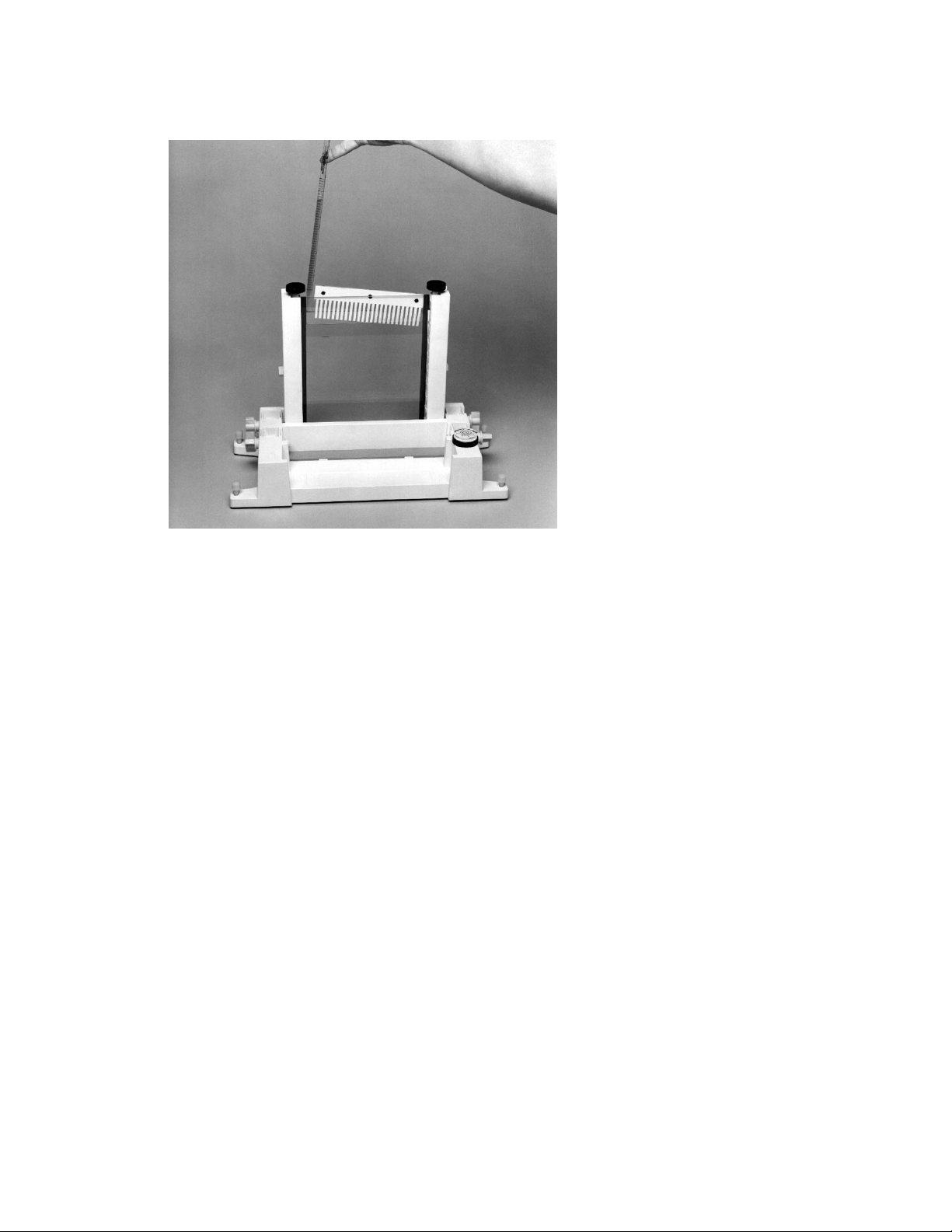
Fig. 4.20. Pouring a CDGE gel.
4. Pour or pipette the gel solution into the sandwich until the gel solution covers the wells of
the comb. Straighten the comb to the desired well depth. Add more gel solution if needed.
5. Allow the gel to polymerize for about 60 minutes. After polymerization, remove the comb
by pulling it straight up slowly and gently.
6. Continue with Section 8 for electrophoresis.
4.3 Introduction to Temporal Temperature Gradient Gel
Electrophoresis (TTGE)
Temporal Temperature Gradient Gel Electrophoresis
14,15
(TTGE) exploits the principle on
which DGGE is based, without requiring a chemical denaturing gradient. Amplified mutant and
wild-type DNA from the gene of interest is loaded onto a polyacrylamide gel containing a
constant concentration of urea. During electrophoresis, the temperature is increased gradually
and uniformly. The result is a linear temperature gradient over the length of the electrophoresis
run. Thus, a denaturing environment is formed by the constant concentration of urea in the gel
in combination with the temporal temperature gradient. With no chemical gradient required,
rapid, high-throughput screening is possible.
The DCode system allows precise control of the temperature ramp rate measured in °C per
hour. Control over the temperature range and ramp rate allows optimum denaturing conditions.
An example of a TTGE gel is shown in Figure 4.21.
36
Page 41

12345
Fig. 4.21. Temporal temperature gradient gel. Amplified mutant and wild-type alleles of exon 7 from the cystic
fibrosis gene. Separation by TTGE run at 130 V for 5 hours in 1.25x TAE buffer on a 6 M urea/6% acrylamide gel
(37.5:1) using a temperature range of 50–60 °C and a ramp rate of 2 °C/hr. Lane 1, mutant allele (1154 insTC); lane 2,
mutant allele (G330X); lane 3, mutant allele (deltaF311); lane 4, mutant allele (R334W); and lane 5, wild-type allele.
(Samples courtesy of L. Silverman, Division of Molecular Pathology, University of North Carolina School of Medicine)
Calculating the Run Parameters
To determine the temperature range to use with TTGE, a melting profile of the DNA sequence
should be generated using a DNA melting software program, such as Bio-Rad’s MacMelt
software. As in DGGE, the addition of a 30–40 base pair GC clamp should be added to one of
the PCR primers to insure that the region screened is in the lowest melting domain. The
temperature range for the gradient can be calculated from the melting profile graph by first
determining the lowest and highest non-GC clamp melting temperature of the DNA sequence
(See example in Figure 4.22). From the calculated low and high temperatures, the
theoretical melting temperatures can be lowered by adding urea to the gel. A denaturing urea
gel will lower the theoretical melting temperature of DNA by 2°C for every mole of urea.
32, 33
In Figure 4.22, the theoretical melting temperature range on the DNA sequence of interest is
approximately 68 to 82 °C. Therefore, the temperature range should be 54–68°C when using
a 7 M urea gel. TTGE gels typically use 6 M of urea, but for sequences that generate melt
profiles that require buffer temperature greater than 70°C, higher concentrations of urea should
be used. Adding 1–2°C to the final temperature may help to improve the resolution of some
mutations. The typical temperature range for TTGE gels are between 40 and 70°C.
Temperature ramp rates of 1–3°C/hr generally give the best resolution between mutant
and wild-type samples. Slower ramp rates are best, but to reduce run times for routine
screening, ramp rates can be increased empirically. The temperature ramp rate can be
determined if the desired run time or temperature range is known. The ramp rate is calculated
by subtracting the final temperature from the initial temperature and dividing by the desired
run time. In Figure 4.22, if the run time is 4 hours, the ramp rate will be 3°C/hr ([68–54°] ÷ 4 hr
= 3.5 °C/hr). A desired run time is calculated by subtracting the final temperature from the
initial temperature and dividing by the desired ramp rate. In the Figure 4.22 example, if the
ramp rate is 2°C/hr, then the run time will be 7 hours ([68– 54°] ÷ 2 °C/hr = 7 hr).
37
Page 42
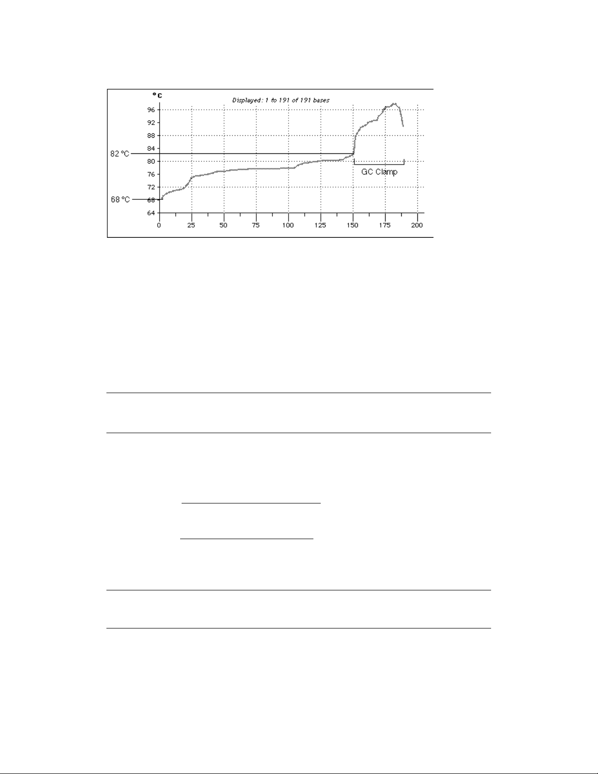
Fig. 4.22. Melting profile of a 191 bp sequence generated with MacMelt software.
Reagent Preparation
The concentration of acrylamide to use varies for the sample being analyzed on the DCode
system. Therefore, a 40% stock solution containing acrylamide and Bis-acrylamide (Bis)
should be made. Reagents for casting and running TTGE gels are included in the DCode
electrophoresis reagent kit for TTGE, catalog number 170-9171.
For different percent crosslinking, use the equation below to determine the amount of Bis
to add. The example stock solution below is for an acrylamide/bis ratio of 37.5:1.
40% Acrylamide/Bis (37.5:1)
Reagent Amount
Acrylamide 38.93 g
Bis-acrylamide 1.07 g
dH2O to 100.0 ml
Filter through a 0.45 µ filter and store at 4 °C.
Polyacrylamide gels are described by reference to two characteristics:
1) The total monomer concentration (%T)
2) The crosslinking monomer concentration (%C)
%T =
gm acrylamide + gm bis-acrylamide
x 100
Total Volume
%C =
g bis-acrylamide
x 100
gm acrylamide + g bis-acrylamide
The table below provides the percentage acrylamide/bis needed for a particular size range.
Gel Percentage Base Pair Separation
6% 300–1,000 bp
8% 200–400 bp
10% 100–300 bp
38
Page 43

40% Acrylamide/Bis Solutions (1.25x TAE, 6M urea)
Reagent 6% Gel 8% Gel 10% Gel 12% Gel
40% Acrylamide/Bis 6.0 ml 8.0 ml 10.0 ml 12.0 ml
50x TAE 1.0 ml** 1.0 ml** 1.0 ml** 1.0 ml**
Urea* 14.4 g 14.4 g 14.4 g 14.4 g
TEMED 40.0 µl 40.0 µl 40.0 µl 40.0 µl
10% Ammonium persulfate 400.0 µl 400.0 µl 400.0 µl 400.0 µl
Total volume 40.0 ml 40.0 ml 40.0 ml 40.0 ml
Add dH2O to 40 ml and mix. Cast the gel immediately after adding the TEMED and
ammonium persulfate.
* For 7 M urea gels, use 16.8 g per 40 ml, for 8 M urea gels, use 19.2 g per 40 ml.
** Adjust this amount for other concentrations of running buffer.
50x TAE Buffer
Reagent Amount Final Concentration
Tris base 242.0 g 2 M
Acetic acid, glacial 57.1 ml 1 M
0.5 M EDTA, pH 8.0 100.0 ml 50 mM
dH2O to 1,000.0 ml
Mix. Autoclave for 20–30 minutes. Store at room temperature.
10% Ammonium Persulfate
Reagent Amount
Ammonium persulfate 0.1 g
dH2O 1.0 ml
Store at –20°C for about a week.
2x Gel Loading Dye
Reagent Amount Final Concentration
2% Bromophenol blue 0.25 ml 0.05%
2% Xylene cyanol 0.25 ml 0.05%
100% Glycerol 7.0 ml 70%
dH2O 2.5 ml
Total volume 10.0 ml
Store at room temperature.
1.25x TAE Running Buffer
Reagent Amount
50x TAE buffer 175 ml
dH2O 6,825 ml
Total volume 7,000 ml
39
Page 44

Gel Volumes
The table below provides the required volume for the gel size and spacer
thickness.
Spacer Thickness 16 x 16 cm gel
0.75 mm 25 ml
1.00 mm 30 ml
1.50 mm 45 ml
Sample Preparation
1. It is important to optimize the PCR reaction to minimize unwanted products which may
interfere with gel analysis. The PCR products should be evaluated for purity by agarose
gel electrophoresis before being loaded onto a denaturing acrylamide gel.
2. For a temporal temperature gradient gel, load 180–300 ng of amplified DNA per well
(usually 5–10% of a 100 µl PCR volume from a 100 ng DNA template). A wild-type
control should be run on every gel.
3. Add an equal volume of 2x gel loading dye to the sample.
Pre-heating the Running Buffer
1. Fill the electrophoresis tank with 7 L of 1.25x TAE buffer.
Note: It is recommended that the running buffer not be reused. Reusing the running buffer
may affect the migration rate and band resolution.
2. Place the temperature control module on top of the electrophoresis tank. Attach the power
cord to the temperature control module, turn the power, pump, and heater on. The clear
loading lid should be on the temperature control module during preheating.
3. Set the temperature controller to the desired temperature. Set the ramp rate to 200°C/hr.
to allow the buffer to reach the desired temperature the quickest.
4. Preheat the buffer to the set temperature. It can take 1 to 1.5 hours for the system to
preheat the buffer to the set temperature. Heating the buffer in a microwave helps reduce
the preheating time.
Assembling the TTGE Gel Sandwich
For the temporal temperature gradient gel format, a 16 x 16 cm gel sandwich size is
recommended. To insure proper alignment, make sure all plates and spacers are clean and
dry before assembling. Use caution when assembling the glass plate sandwiches. Wear
gloves and eye protection at all times.
1. Assemble the gel sandwich on a clean surface. Lay the large rectangular plate down first, then
place the spacers of equal thickness along the short edges of the larger rectangular plate.
2. Place the short glass plate on top of the spacers so that it is flush with the bottom edge
of the long plate.
3. Loosen the black thumb screw of each sandwich clamp by turning it counterclockwise.
Place each clamp at the appropriate side of the gel sandwich with the locating arrows
facing up and toward the glass plates (Figure 4.24).
40
Page 45
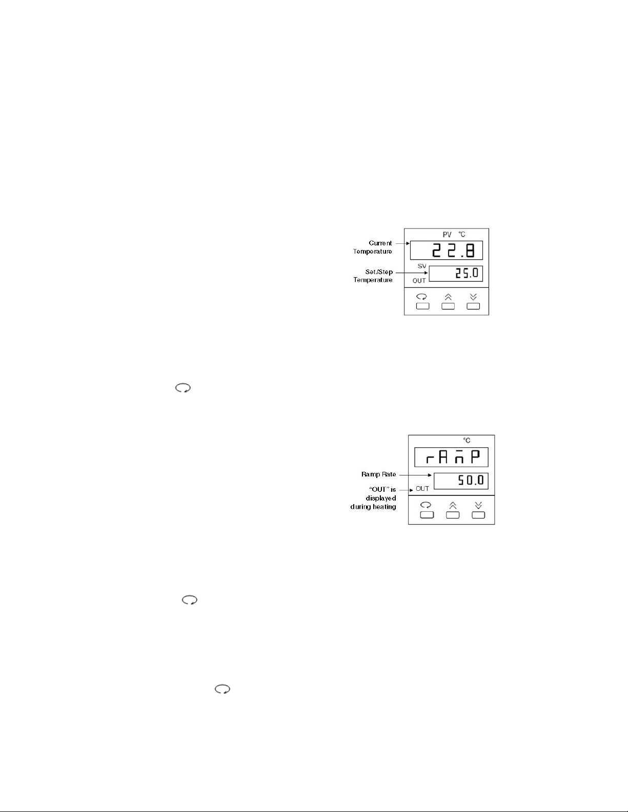
Temperature Controller
The temperature controller maintains the desired buffer temperature in the DCode system.
Turning on the Controller
Turn the controller on by pressing the power button and wait for the controller to
initialize. The controller will display the following screens in order:
• The program code
• The date code and serial code
• The hours used
• The temperature control screen (see Fig. 1).
The controller is now ready to be
programmed.
Setting the Set Temperature and Ramp Rate
1. From the temperature control screen,
use the arrow keys to adjust the Set
Temperature to your desired target
temperature in °C (Fig. 1)
2. Use the key to display the ramp
control screen. (Fig. 2.)
3. From the ramp control screen, use
the arrow keys to set the desired
temperature Ramp Rate in °C per hour.
Note that the maximum ramp rate for
the DCode is 50°C /hr. If the target
Ramp Rate is set using the controller
to higher than 50°C /hr the maximum
ramp rate of 50°C /hr will be used.
4. To toggle between the temperature control
screen and the ramp control screen, or to
review the set temperature and ramp rate,
press the key at any time
Note: Following programming by default the controller displays the Step Temperature rather
than the Set Temperature (see Fig 1. below). The step temperature is the next temperature
value the system will reach as it heats/cools to reach set temperature. To display the Set
Temperature press the key.
41
Fig. 1. Temperature Control Screen.
Fig. 2. Ramp Control Screen.
Page 46
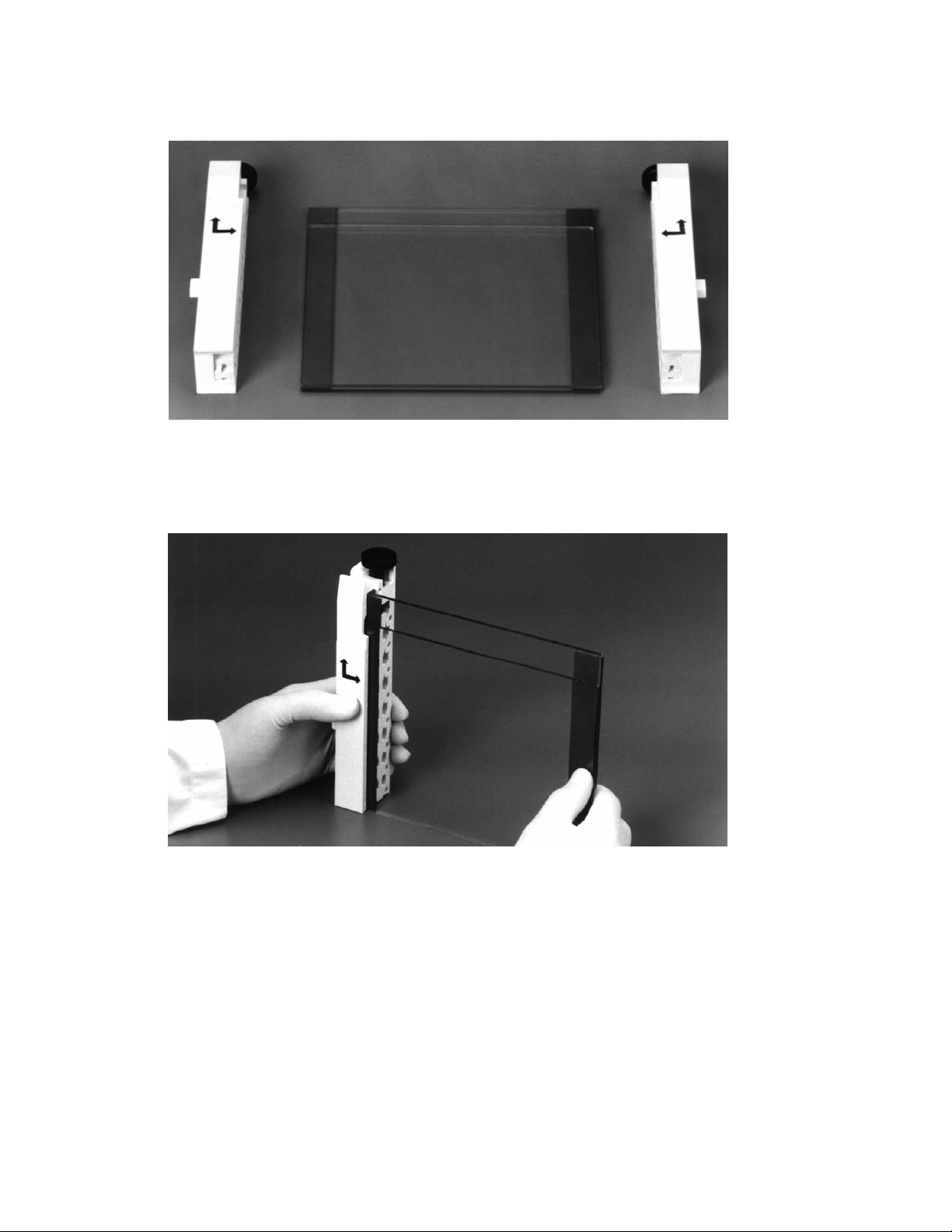
Fig. 4.24. Positioning glass plates, spacers, and clamps.
4. Grasp the gel sandwich firmly. Guide the left and right clamps onto the sandwich so that
the long and short plates fit the appropriate notches in the clamp (Figure 4.25). Tighten the
screws enough to hold the plates in place.
Fig. 4.25. Attaching the clamps to the glass plate assembly.
5. Place the sandwich assembly in the alignment slot (the slot without cams) of the casting
stand with the short glass plate forward (Figure 4.26). Loosen the sandwich clamps and
insert an alignment card to keep the spacers parallel to the clamps.
Note: Always use the alignment slot and alignment card to set the spacers in place. Failure
to use these can result in gel leakage when casting, as well as buffer leakage during the
run.
42
Page 47
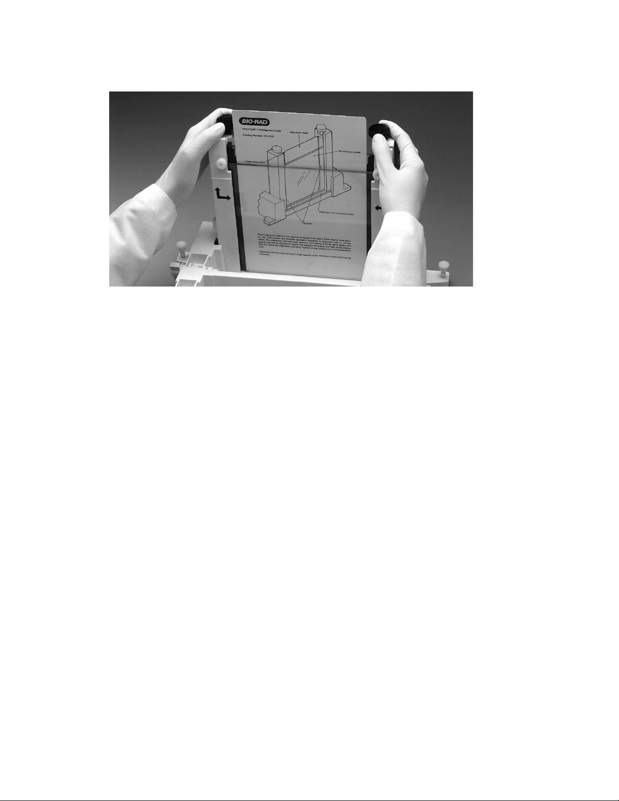
Fig. 4.26. Aligning spacers in the sandwich assembly.
6. Align the plates and spacers by simultaneously pushing inward on both clamps at the
locating arrows while, at the same time, pushing down on the spacers with your thumbs.
Tighten both clamps just enough to hold the sandwich in place. Pushing inward on both
clamps at the locating arrows will insure that the spacers and glass plates are flush against
the sides of the clamps (Figure 4.26).
7. Remove the alignment card. Remove the sandwich assembly from the casting stand and
check that the plates and spacers are flush at the bottom. If they are not flush, realign the
sandwich and spacers to obtain a good seal (Repeat steps 5–7).
8. When a good alignment and seal is obtained, tighten the clamp screws until it is finger-tight.
Casting TTGE Gels
1. Place the gray sponge onto the front casting slot. The camshafts on the casting stand
should have the handles pointing up and pulled out. Place the sandwich assembly on the
sponge with the shorter plate facing forward. When the sandwich is placed correctly, press
down on the sandwich and turn the handles of the camshaft down so that the cams lock
the sandwich in place.
2. Into a 50 ml tube, add the required amount of gel solution (Section 4.3). Add a final
concentration of 0.09% (v/v) each of ammonium persulfate and TEMED solution. Cap
the tube and mix.
3. Insert a comb in the gel sandwich and tilt it so the teeth are at a slight angle. This will prevent
air from being trapped under the comb teeth when pouring the gel solution (Figure 4.27).
43
Page 48

Fig. 4.27. Pouring a TTGE gel.
4. Pour or pipette the gel solution into the sandwich until the gel solution covers the wells of
the comb. Straighten the comb to the desired well depth. Add more solution if needed.
5. Allow the gel to polymerize for about 60 minutes. After polymerization, remove the comb
by pulling it straight up slowly and gently.
6. Continue with Section 8 for electrophoresis.
Section 5
Heteroduplex Analysis
5.1 Introduction to Heteroduplex Analysis
Heteroduplex Analysis (HA) is based on conformational differences in double-stranded
DNA caused by the formation of heteroduplex molecules.6Heteroduplex molecules have a
mismatch in the double-strand, causing a distortion in its usual conformation and can be
detected on polyacrylamide gels due to slower migration than the corresponding homoduplex
molecules. Heteroduplex molecules with as little as one mismatch can show a difference in
mobility in a gel than homoduplex molecules. Heteroduplexes are generated in the following
ways: during PCR of a heterozygous individual or by adding mutant and wild-type DNA in
the same PCR reaction or by denaturation and renaturation of mutant and wild-type DNA in
a single tube. Both mutant and wild-type samples are run on the same gel and the mobility of
the fragments is compared.
The sensitivity of heteroduplex analysis is 80–90% in small DNA fragments (< 300 bp).
16
The sensitivity of mutation detection can be improved when used in conjunction with SSCP.
17
A polyacrylamide analog has been developed (MDE™or DEM™) which enhances the ability to
detect mutations in heteroduplex samples when compared to conventional polyacrylamide
gels.18The addition of urea to the gel can create a mildly denaturing condition which can
increase the separation of heteroduplexes and make mutation detection easier.
16
44
Page 49

A variation of heteroduplex analysis is Conformation Sensitive Gel Electrophoresis
(CSGE). This technique exploits the observation that a mildly denaturing environment will
enhance the ability of single-based mismatches to produce conformational changes.19These
changes also increase the differential migration of heteroduplex and homoduplex molecules.
Samples are electrophoresed in 6–10% polyacrylamide gels (99:1), tris-taurine buffer and
10% ethylene glycol with 15% formamide as denaturants. Bis (acryloyl) piperazine (BAP) or
piperazine diacrylamide (PDA) can also be used instead of bis as a cross-linker.20BAP or
PDA cross-linker helps to improve the gel strength and increase the pore size in the gel. PCR
fragment sizes for CSGE typically run between 300–800 bp in length for optimum mutation
detection.
21
5.2 Reagent Preparation
Heteroduplex Analysis
The concentration and type of acrylamide to use varies for the sample being analyzed on
the DCode system. Therefore, a 40% stock solution containing acrylamide and bis-acrylamide
(bis) should be made, or a 2x DEM solution. Reagents for casting and running a heteroduplex
analysis gel are included in the DCode electrophoresis reagent kit for Heteroduplex Analysis,
catalog number 170-9173.
For a different percent crosslinking, use the equation below to determine the amount of bis
to add. The example stock solution below is for an acrylamide/bis ratio of 37.5:1.
40% Acrylamide/Bis (37.5:1)
Reagent Amount
Acrylamide 38.93 g
Bis-acrylamide 1.07 g
dH2O to 100.0 ml
Filter through a 0.45 µ filter and store at 4°C.
Polyacrylamide gels are described by reference to two characteristics:
1) The total monomer concentration (%T)
2) The crosslinking monomer concentration (%C)
%T =
g acrylamide + g bis-acrylamide
x 100
Total Volume
%C =
g bis-acrylamide
x 100
g acrylamide + g bis-acrylamide
10x TBE Buffer
Reagent Amount Final Concentration
Tris base 108 g 0.89 M
Boric acid 55 g 0.89 M
0.5 M EDTA, pH 8.0 40 ml 20 mM
dH2O to 1L
Mix and add dH2O to 1 L. Autoclave for 20–30 minutes. Store at room temperature.
45
Page 50

40% Acrylamide/Bis Solutions (1x TBE)
Reagent 6% Gel 8% Gel 10% Gel 12% Gel
40% Acrylamide/Bis 6 ml 8 ml 10 ml 12 ml
10x TBE (see note) 4 ml 4 ml 4 ml 4 ml
Urea (optional) see note see note see note see note
TEMED 40 µl 40 µl 40 µl 40 µl
10% Ammonium persulfate 400 µl 400 µl 400 µl 400 µl
Total volume 40 ml 40 ml 40 ml 40 ml
Add dH2O to 40 ml and mix. Cast the gel immediately after adding the TEMED and ammonium
persulfate.
Note: For 0.5x TBE, add 2 ml.
For 15% urea, add 6 gm.
2x DEM Solution (0.6x TBE)
Reagent 1x Gel 0.8x Gel
2x DEM 20 ml 16 ml
10x TBE (see note) 2.4 ml 2.4 ml
Urea (optional) see note see note
TEMED 40 µl 40 µl
10% Ammonium persulfate 400 µl 400 µl
Total volume 40 ml 40 ml
Add dH2O to 40 ml and mix. Cast the gel immediately after adding the TEMED and ammonium
persulfate.
Note: For 0.5x TBE, add 2 ml.
For 1x TBE, add 4 ml.
For 15% urea, add 6 gm.
10% Ammonium Persulfate
Reagent Amount
Ammonium persulfate 0.1 g
dH2O 1.0 ml
Store at –20°C for about a 1 week.
2x Gel Loading Dye
Reagent Amount Final Concentration
2% Bromophenol blue 0.25 ml 0.05%
2% Xylene cyanol 0.25 ml 0.05%
100% Glycerol 7.0 ml 70%
dH2O 2.5 ml
Total volume 10.0 ml
Store at room temperature.
1x TBE Running Buffer
Reagent 2 L Buffer 7 L Buffer
10x TBE buffer 200 ml 700 ml
dH2O 1,800 ml 6,300 ml
0.6x TBE Running Buffer
Reagent 2 L Buffer 7 L Buffer
10x TBE buffer 120 ml 420 ml
dH2O 1,880 ml 6,580 ml
46
Page 51

CSGE Analysis
For a different percent crosslinking, use the equation in the heteroduplex analysis reagent
preparation to determine the amount of crosslinker to add. The example stock solution below
is for an acrylamide/PDA ratio of 99:1.
40% Acrylamide/PDA (99:1)
Reagent Amount
Acrylamide 198.0 g
PDA or BAP 2.0 g
dH2O to 500.0 ml
Filter through a 0.45 µ filter. Store at 4°C.
10x TTE Buffer
Reagent Amount Final Concentration
Tris base 107.8 g 0.89 M
Taurine 18.8 g 0.15 M
EDTA 1.9 g 5 mM
dH2O to 1,000 ml
Mix. Autoclave for 20–30 minutes. Store at room temperature.
10% Acrylamide/PDA Gel
Reagent Amount Final Concentration
40% Acrylamide/PDA (see note) 10.0 ml 10%
10x TTE 2.0 ml 0.5x
Formamide 6.0 ml 15%
Ethylene Glycol 4.0 ml 10%
dH2O 17.6 ml
TEMED 40.0 µl
10% Ammonium persulfate 400.0 µl
Total volume 40.0 ml
Mix. Cast the gel immediately after adding the TEMED and ammonium persulfate.
Note: For 6% acrylamide gel use 6 ml of a 40% stock.
For 8% acrylamide gel use 8 ml of a 40% stock.
For 12% acrylamide gel use 12 ml of a 40% stock.
1x TTE Lower Chamber Running Buffer
Reagent 2 L Buffer 7 L Buffer
10x TTE buffer 200 ml 700 ml
dH2O 1,800 ml 6,300 ml
0.25x TTE Upper Chamber Running Buffer
Reagent 400 ml Buffer
10x TTE buffer 10 ml
dH2O 390 ml
5.3 Gel Volumes
The table below provides the required volume for the gel size and spacer thickness.
Spacer Thickness 20 x 20 cm Gel
0.75 mm 30 ml
1.00 mm 40 ml
47
Page 52

5.4 Sample Preparation
1. It is important to optimize the PCR reaction to minimize unwanted products which may
interfere with gel analysis. Heteroduplexes can be generated during PCR by amplifying
the mutant and wild-type samples in the same tube. If the samples are amplified in
separate tubes, then heteroduplexes can be formed by mixing an equal amount of mutant
and wild-type samples in one tube. Heat the tube at 95°C for 5 minutes, then place at 65°C
for 1 hour and let slowly cool to room temperature.
2. The PCR products should be evaluated for purity by agarose gel electrophoresis before
being loaded onto a heteroduplex gel.
3. About 180–500 ng of heteroduplex DNA (usually 5–15% of the total PCR volume) can
be loaded per well.
4. Add an equal amount of 2x gel loading dye to the samples.
5.5 Adding the Running Buffer
1. Remove and place the temperature control module on the DCode lid stand.
2. Add 2 or 7 L of running buffer to the electrophoresis tank. For CSGE, the upper buffer
concentration is different from the lower buffer concentration; therefore, the pump should
not be used.
Note: To improve heat dissipation during electrophoresis, 7 L of buffer can be used.
3. Place the temperature control module on the electrophoresis tank.
48
Page 53

5.6 Temperature Controller
The temperature controller maintains the desired buffer temperature in the DCode system.
Turning on the Controller
Turn the controller on by pressing the power button and wait for the controller to
initialize. The controller will display the following screens in order:
• The program code
• The date code and serial code
• The hours used
• The temperature control screen (see Fig. 1).
The controller is now ready to be
programmed.
Setting the Set Temperature and Ramp Rate
1. From the temperature control screen,
use the arrow keys to adjust the Set
Temperature to your desired target
temperature in °C (Fig. 1)
2. Use the key to display the ramp
control screen. (Fig. 2.)
3. From the ramp control screen, use
the arrow keys to set the desired
temperature Ramp Rate in °C per hour.
Note that the maximum ramp rate for
the DCode is 50°C /hr. If the target
Ramp Rate is set using the controller
to higher than 50°C /hr the maximum
ramp rate of 50°C /hr will be used.
4. To toggle between the temperature control
screen and the ramp control screen, or to
review the set temperature and ramp rate,
press the key at any time
Note: Following programming by default the controller displays the Step Temperature rather
than the Set Temperature (see Fig 1. below). The step temperature is the next temperature
value the system will reach as it heats/cools to reach set temperature. To display the Set
Temperature press the key.
49
Fig. 1. Temperature Control Screen.
Fig. 2. Ramp Control Screen.
Page 54
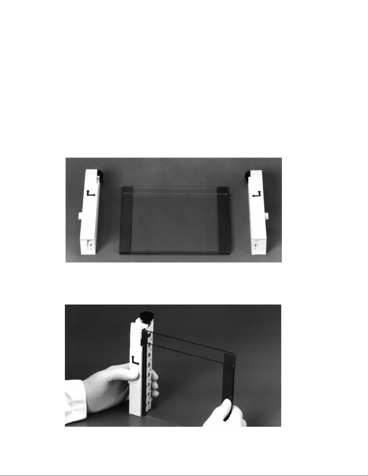
5.7 Assembly of a Heteroduplex Analysis Gel Sandwich
For the heteroduplex gel format, a 20 x 20 cm gel sandwich is recommended. To insure proper
alignment, make sure all plates and spacers are clean and dry before assembly. Use caution when
assembling the glass plate sandwiches. Wear gloves and eye protection at all times.
1. Assemble the gel sandwich on a clean surface. Lay the large rectangular plate down first,
then place the left and right spacers of equal thickness along the short edges of the larger
rectangular plate.
2. Place a short glass plate on top of the spacers so that it is flush with the bottom edge of
the long plate.
3. Loosen the single screw of each sandwich clamp by turning it counterclockwise. Place
each clamp by the appropriate side of the gel sandwich with the locating arrows facing up
and toward the glass plates (Figure 5.2).
Fig. 5.2. Positioning glass plates, spacers, and clamps.
4. Grasp the gel sandwich firmly. Guide the left and right clamps onto the sandwich so that
the long and short plates fit the appropriate notches in the clamp (Figure 5.3). Tighten
the screws enough to hold the plates in place.
Fig. 5.3. Attaching the clamps to the glass plate assembly.
50
Page 55

5. Place the sandwich assembly in the alignment slot (the slot without cams) of the casting
stand with the short glass plate forward (Figure 5.4). Loosen the sandwich clamps and
insert an alignment card to keep the spacers parallel to the clamps.
Note: Always use the alignment slot and alignment card to set the spacers in place. Failure
to use these can result in gel leakage when casting, as well as buffer leakage during the
run.
6. Align the plates and spacers by simultaneously pushing inward on both clamps at the locating
arrows while pushing down on the spacers with your thumbs. Tighten both clamps just enough
to hold the sandwich in place. Pushing inward on both clamps at the locating arrows will insure
that the spacers and glass plates are flush against the sides of the clamps (Figure 5.4).
Fig. 5.4. Aligning spacers in the sandwich assembly.
7. Remove the alignment card. Remove the sandwich assembly from the casting stand and
check that the plates and spacers are flush at the bottom. If they are not flush, realign the
sandwich and spacers for a good seal (Repeat steps 5–7).
8. When a good alignment and seal are obtained, tighten the clamp screws until it is finger-tight.
5.8 Casting Heteroduplex Analysis Gels
1. Place the gray sponge onto the front casting slot. The camshafts on the casting stand
should have the handles pointing up and pulled out. Place the sandwich assembly on the
sponge with the shorter plate facing forward. When the sandwich is placed correctly, press
down on the sandwich and turn the handles of the camshaft down so that the cams lock
the sandwich in place.
2. Into a 50 ml tube, add the required amounts of DEM solution (Section 5.2). Add a final
concentration of 0.09% (v/v) each of ammonium persulfate and TEMED solutions. Cap the
tube and mix.
3. Insert a comb in the gel sandwich and tilt it so that the teeth are at a slight angle. This will
prevent air from being trapped under the comb teeth when pouring the gel solution
(Figure 5.5).
51
Page 56
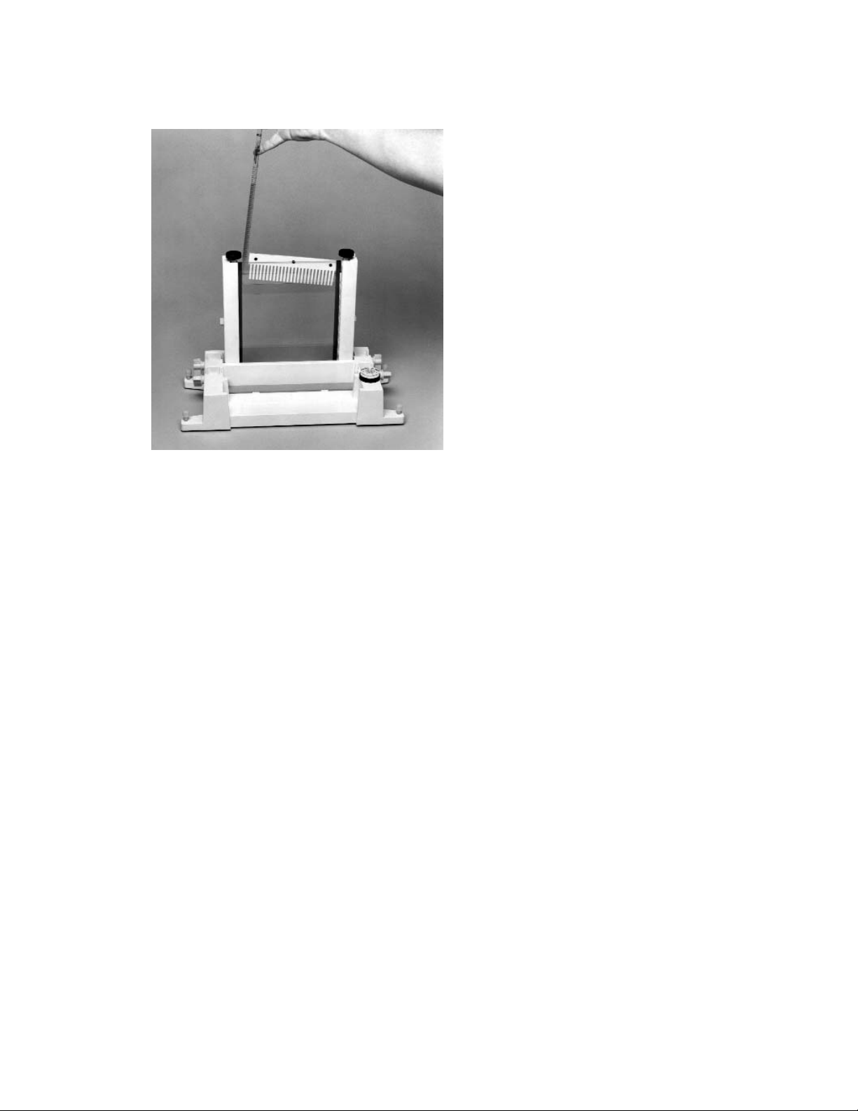
Fig. 5.5. Pouring a heteroduplex analysis gel.
4. Pour or pipette the gel solution into the sandwich until it covers the wells of the comb.
Straighten the comb to the desired well depth. Add more solution if needed.
5. Allow the gel to polymerize for about 60 minutes. After polymerization, remove the comb
by pulling it straight up slowly and gently.
6. Continue with Section 8 for electrophoresis.
Section 6
Single-Stranded Conformational Polymorphisms
6.1 Introduction to SSCP
The SSCP technique is based on the fact that single-stranded DNA has a sequence-specific
secondary structure. Sequence differences as small as a single base change can affect this
secondary structure and can be detected by electrophoresis in a nondenaturing polyacrylamide gel.
1
Double-stranded mutant and wild-type samples are first denatured into single strands and then
loaded onto the gel. Differences in mobility of the single strands between the control wild-type DNA
and the other samples indicate a mutation. SSCP is a widely used mutation screening method
because of its simplicity. However, since experimental conditions cannot be predicted for a
particular DNA, it is important to optimize gel electrophoresis conditions. The ability to detect
single base changes rests on several factors which optimize band resolution.
1. Fragment size: The estimated efficiency for detecting single base changes is 90–95% for
fragments less than 350 bp, but the efficiency will decrease as the length of fragment
increases.
22
2. Gel temperature: Migration differences due to a single mutation are observed at buffer
temperatures between 4–25°C. Optimal temperature must be determined empirically.
3. Gel additives: In some cases, 5–10% glycerol can be added to the gel to improve the mobility
differences in fragments. Since glycerol can reduce the mobility of single-stranded DNA
fragments at low temperatures, it is typically used with gels run near room temperature.
22
52
Page 57
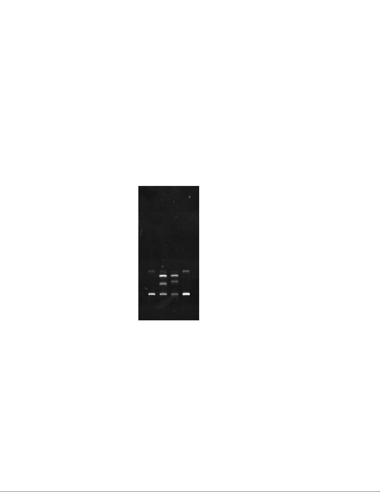
4. Crosslinking ratio: The acrylamide/bis ratio determines the percent of crosslinking. SSCP
gels generally use 1–2 % crosslinking. Acrylamide concentrations will vary from 5% to 10%.
5. Buffer concentration: Gels are run with TBE buffer at concentrations of 0.5x or 1.0x. In
some cases, 0.5x TBE appears to give slightly better results than 1.0x TBE.
23
SSCP protocols have typically used radioisotope-labeled fragments, but recently nonra-
dioactive or “cold SSCP” methods have been developed.24For a more complete description
of the SSCP technique, refer to references 1, 22, and 25–29.
When connected to an appropriate external chiller, the DCode system can control the
buffer temperatures between 5–25°C. The electrophoresis cooling tank is outfitted with two
cooling fingers. Tygon tubing connects the cooling fingers in the electrophoresis tank to an
external chiller. The chiller recirculates a coolant through the cooling fingers which, in turn,
cools the buffer. The external chiller is set to chill the coolant to approximately –20°C, and the
DCode heater regulates the buffer temperature. An example of an SSCP gel run on the DCode
system is shown in Figure 6.1.
12 3 4
Fig. 6.1. Amplified mutant and wild-type alleles of exon 8 from the p53 gene. Separation by SSCP run at constant
30 W for 3.5 hours in 1x TBE on an 8% acrylamide gel (37.5:1) with 3.5% glycerol at 8°C. Lane 1, undenatured mutant allele;
lane 2, mutant allele; lane 3, wild-type allele; lane 4, undenatured wild-type allele.
53
Page 58

6.2 Reagent Preparation
The concentration and type of acrylamide to use varies for the sample being analyzed on
the DCode system; therefore, a 40% stock solution containing acrylamide and bis-acrylamide
(bis) should be made. Reagents for casting and running an SSCP gel are included in the
DCode electrophoresis reagent kit for SSCP, catalog number 170-9172.
For a different percent crosslinking, use the equation below to determine the amount of bis
to add. The example stock solution below is for an acrylamide/bis ratio of 37.5:1.
40% Acrylamide/Bis (37.5:1)
Reagent Amount
Acrylamide 38.93 g
Bis-acrylamide 1.07 g
dH2O to 100.0 ml
Filter through a 0.45 µ filter and store at 4°C.
Polyacrylamide gels are described with reference to two characteristics:
1) The total monomer concentration (%T)
%T =
g acrylamide + g bis-acrylamide
x 100
Total Volume
2) The crosslinking monomer concentration (%C)
%C =
g bis-acrylamide
x 100
g acrylamide + g bis-acrylamide
10x TBE Buffer
Reagent Amount Final Concentration
Tris base 108 g 0.89 M
Boric acid 55 g 0.89 M
0.5 M EDTA, pH 8.0 40 ml 20 mM
dH2O to 1L
Mix. Autoclave for 20–30 minutes. Store at room temperature.
40% Acrylamide/Bis Solutions (1x TBE)
Reagent 6% Gel 8% Gel 10% Gel 12% Gel
40% Acrylamide/Bis 6 ml 8 ml 10 ml 12 ml
10x TBE (see note) 4 ml 4 ml 4 ml 4 ml
100% Glycerol (optional) see note see note see note see note
TEMED 40 µl 40 µl 40 µl 40 µl
10% Ammonium persulfate 400 µl 400 µl 400 µl 400 µl
dH2O to 40 ml to 40 ml to 40 ml to 40 ml
Add dH2O to 40 ml and mix. Cast the gel immediately after adding the TEMED and ammonium
persulfate.
Note: 0.5x TBE, add 2 ml.
5% glycerol, add 2 ml.
10% glycerol, add 4 ml.
54
Page 59

Using Acrylamide and Bis-acrylamide Stock Solutions
Use these calculations to determine the necessary volumes of stock acrylamide and
bis-acrylamide solutions to produce gels of any percent and volume.
To determine the monomer and crosslinker ratios:
1. (A) is the part of total monomer that is acrylamide
A =
gm acrylamide
gm acrylamide + gm bis-acrylamide
2. (B) is the part of total monomer that is bis-acrylamide
B =
gm bis-acrylamide
gm acrylamide + gm bis-acrylamide
To determine the volume of 40% acrylamide stock solution to use:
3. Use the calculation for (A) determined above.
(A) (gel %) (final volume)
= ml of 40% acrylamide (C)
(40%) acrylamide solution
4. Use the calculation for (B) determined above.
(B) (gel %)(final volume)
= ml of 2% bis-acrylamide (D)
(2%) bis-acrylamide solution
Acrylamide/Bis Solutions (1x TBE)
Reagent 8% Gel (37.5:1) X% Gel
40% Acrylamide 7.78 ml (C) from above
2% Bis 4.27 ml (D) from above
10x TBE (see note) 4 ml 4 ml
100% Glycerol (optional) see note see note
TEMED 40 µl 40 µl
10% Ammonium persulfate 400 µl 400 µl
dH2O to 40 ml to 40 ml
Cast the gel immediately after adding the TEMED and ammonium persulfate.
Optional: 0.5x TBE, add 2 ml
5% glycerol, add 2 ml
10% glycerol, add 4 ml
10% Ammonium Persulfate
Reagent Amount
Ammonium persulfate 0.1 g
dH2O 1.0 ml
Store at –20°C for about a week.
2x Gel Loading Dye
Reagent Amount Final Concentration
Bromophenol blue 0.05 g 0.05%
Xylene cyanol 0.05 g 0.05%
Formamide 9.5 ml 95%
0.5 M EDTA, pH 8 0.4 ml 20 mM
Total volume 10.0 ml
Store at room temperature.
55
Page 60

1x TBE Running Buffer
Reagent Amount
10x TBE buffer 700 ml
dH2O 6,300 ml
6.3 Gel Volumes
The table below provides the required volume for the gel size and spacer thickness.
Spacer Thickness 20 x 20 cm Gel
0.75 mm 30 ml
1.00 mm 40 ml
6.4 Sample Preparation
1. It is important to optimize the PCR reaction to minimize unwanted products which may
interfere with gel analysis. The PCR products should be evaluated for purity by agarose
gel electrophoresis before being loaded onto an SSCP gel.
2. 150–300 ng of amplified DNA (usually 5–10% of the total PCR volume) can be loaded per
well. Aliquot the proper amount of sample into separate tubes and add equal volume of
2x SSCP gel loading dye. For extra control, the undenatured samples can be run on the
gel.
3. Denature the samples at 95°C for 5 minutes and then place on ice.
56
Page 61
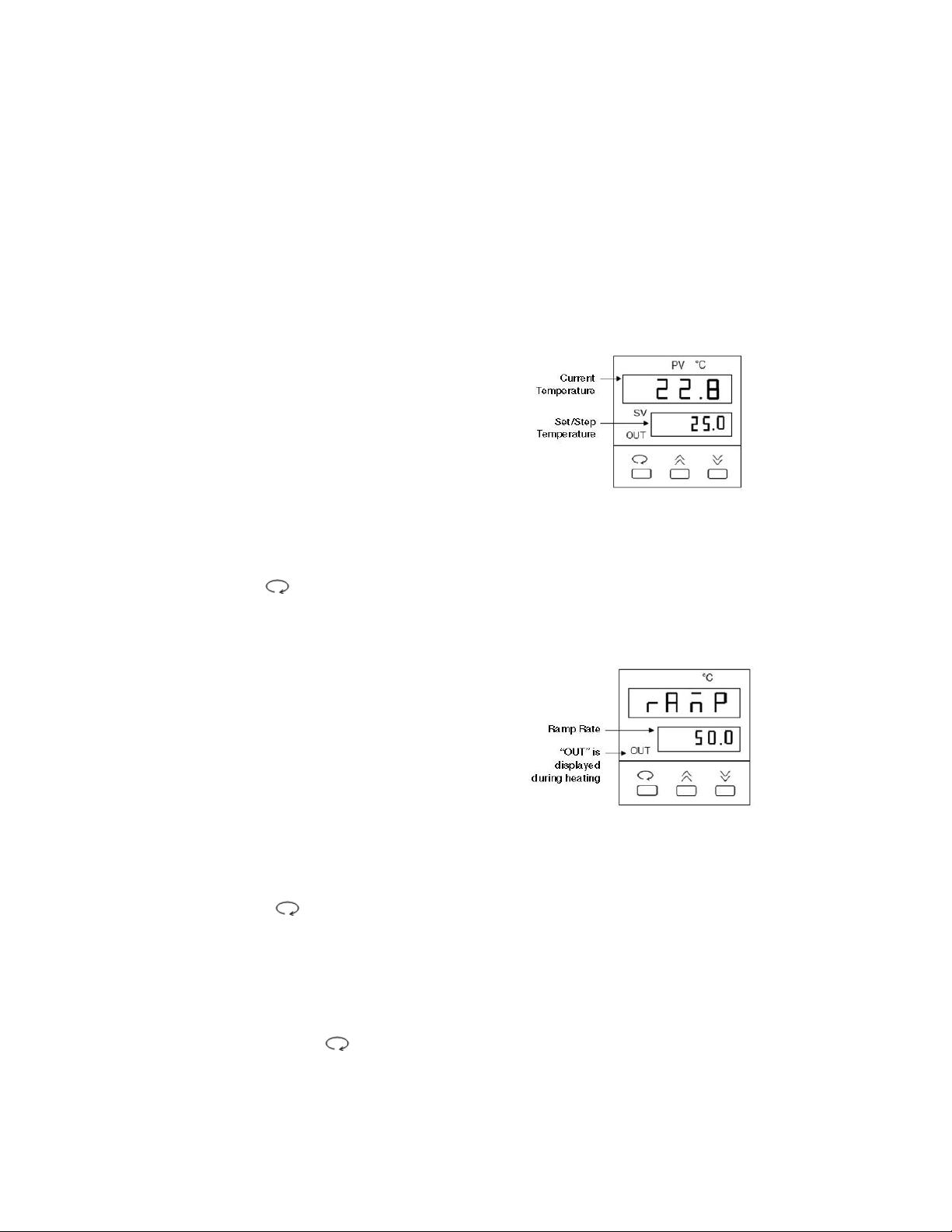
6.5 Temperature Controller
The temperature controller maintains the desired buffer temperature in the DCode system.
Turning on the Controller
Turn the controller on by pressing the power button and wait for the controller to
initialize. The controller will display the following screens in order:
• The program code
• The date code and serial code
• The hours used
• The temperature control screen (see Fig. 1).
The controller is now ready to be
programmed.
Setting the Set Temperature and Ramp Rate
1. From the temperature control screen,
use the arrow keys to adjust the Set
Temperature to your desired target
temperature in °C (Fig. 1)
2. Use the key to display the ramp
control screen. (Fig. 2.)
3. From the ramp control screen, use
the arrow keys to set the desired
temperature Ramp Rate in °C per hour.
Note that the maximum ramp rate for
the DCode is 50°C /hr. If the target
Ramp Rate is set using the controller
to higher than 50°C /hr the maximum
ramp rate of 50°C /hr will be used.
4. To toggle between the temperature control
screen and the ramp control screen, or to
review the set temperature and ramp rate,
press the key at any time
Note: Following programming by default the controller displays the Step Temperature rather
than the Set Temperature (see Fig 1. below). The step temperature is the next temperature
value the system will reach as it heats/cools to reach set temperature. To display the Set
Temperature press the key.
57
Fig. 1. Temperature Control Screen.
Fig. 2. Ramp Control Screen.
Page 62

6.6 Cooling the Running Buffer and Chiller Settings
1. To chill the buffer in the DCode system, an external chiller is required. For buffer
temperature runs between 5–20°C, the chiller must be able to be set to –20°C and have
a built-in pump to recirculate the coolant (recommended chillers: Haake Model K20 and
Lauda Model RMS-6 or equivalent).
2. Add enough 50% ethylene glycol to the external chiller to fill the coolant reservoir.
Note: To achieve maximum chilling in the electrophoresis cooling tank, do not use ethylene
glycol concentrations greater than 50%.
3. Fill the DCode electrophoresis cooling tank with 7 L of desired running buffer.
Note: It is recommended that the running buffer not be re-used. Because this may affect
the migration rate and band resolution.
4. Connect two pieces of Tygon tubing to the inlet and outlet on the external chiller. Attach
the quick-release connectors to the other end of the tubing.
5. Connect the quick-release tubing connections to the cooling finger leads on the back of the
tank. Turn the chiller on and set the temperature to –20°C. Setting the chiller to –20°C
assures maximum chilling effect, but some chillers may not reach the set temperature due
to the 50% ethylene glycol concentration. Place the temperature control module onto the
electrophoresis tank. The clear loading lid should be on the temperature control module.
Note: For electrophoresis runs between 20–25°C, the chiller should be set to –5 to 0°C.
6. Attach the power cord. Turn the power, pump, and heater on. Set to the desired running
temperature, with a temperature ramp rate to 200°C/hr. This allows the buffer to reach the
desired temperature the quickest.
7. Pre-chill the buffer to the set temperature. It can take 1–1.5 hours for the system to chill
the buffer to 5–10°C. Pre-chilling the buffer overnight at 4°C helps reduce the pre-chilling
time.
6.7 Assembling the SSCP Gel Sandwich
For SSCP gel formats, a 20 x 20 cm gel sandwich size is recommended. To insure proper
alignment, make sure all plates and spacers are clean and dry before assembly. Use caution
when assembling the glass plate sandwiches. Wear gloves and eye protection at all times.
1. Assemble the gel sandwich on a clean surface. Lay the large rectangular plate down first,
then place the left and right spacers of equal thickness along the short edges of the larger
rectangular plate.
2. Place a short glass plate on top of the spacers so that it is flush with the bottom edge of
the long plate.
3. Loosen the single screw of each sandwich clamp by turning it counterclockwise. Place
each clamp by the appropriate side of the gel sandwich with the locating arrows facing up
and toward the glass plates (Figure 6.3).
58
Page 63

Fig. 6.3. Positioning glass plates, spacers, and clamps.
4. Grasp the gel sandwich firmly. Guide the left and right clamps onto the sandwich so that
the long and short plates fit the appropriate notches in the clamp (Figure 6.4). Tighten
the screws enough to hold the plates in place.
Fig. 6.4. Attaching the clamps to the glass plate assembly.
5. Place the sandwich assembly in the alignment slot (the slot without cams) of the casting
stand with the short glass plate forward (Figure 6.5). Loosen the sandwich clamps and
insert an alignment card to keep the spacers parallel to the clamps.
Note: Always use the alignment slot and alignment card to set the spacers in place. Failure
to use these can result in gel leakage when casting, as well as buffer leakage during the
run.
6. Align the plates and spacers by simultaneously pushing inward on both clamps at the
locating arrows while, at the same time, pushing down on the spacers with your thumbs.
Tighten both clamps just enough to hold the sandwich in place. Pushing inward on both
clamps at the locating arrows will insure that the spacers and glass plates are flush against
the sides of the clamps (Figure 6.5).
59
Page 64

Fig. 6.5. Aligning spacers in the sandwich assembly.
7. Remove the alignment card. Remove the sandwich assembly from the casting stand and
check that the plates and spacers are flush at the bottom. If the spacers and glass plates
are not flush, realign the sandwich and spacers to obtain a good seal (Repeat steps 5–7).
8. Once a good alignment and seal are obtained, tighten the clamp screws until it is finger-tight.
6.8 Casting SSCP Gels
1. Place the gray sponge onto the front casting slot. The camshafts on the casting stand
should have the handles pointing up and pulled out. Place the sandwich assembly on the
sponge with the shorter plate facing forward. When the sandwich is placed correctly, press
down on the sandwich and turn the handles of the camshaft down so that the cams lock
the sandwich in place.
2. Into a 50 ml tube, add the required amounts of solutions (Section 6.2). Add a final
concentration of 0.09% (v/v) each of ammonium persulfate and TEMED solutions. Cap the
tube and mix.
3. Insert a comb in the gel sandwich and tilt it so the teeth are at a slight angle. This will
prevent air from being trapped under the comb teeth while pouring the gel solution
(Figure 6.6).
60
Page 65
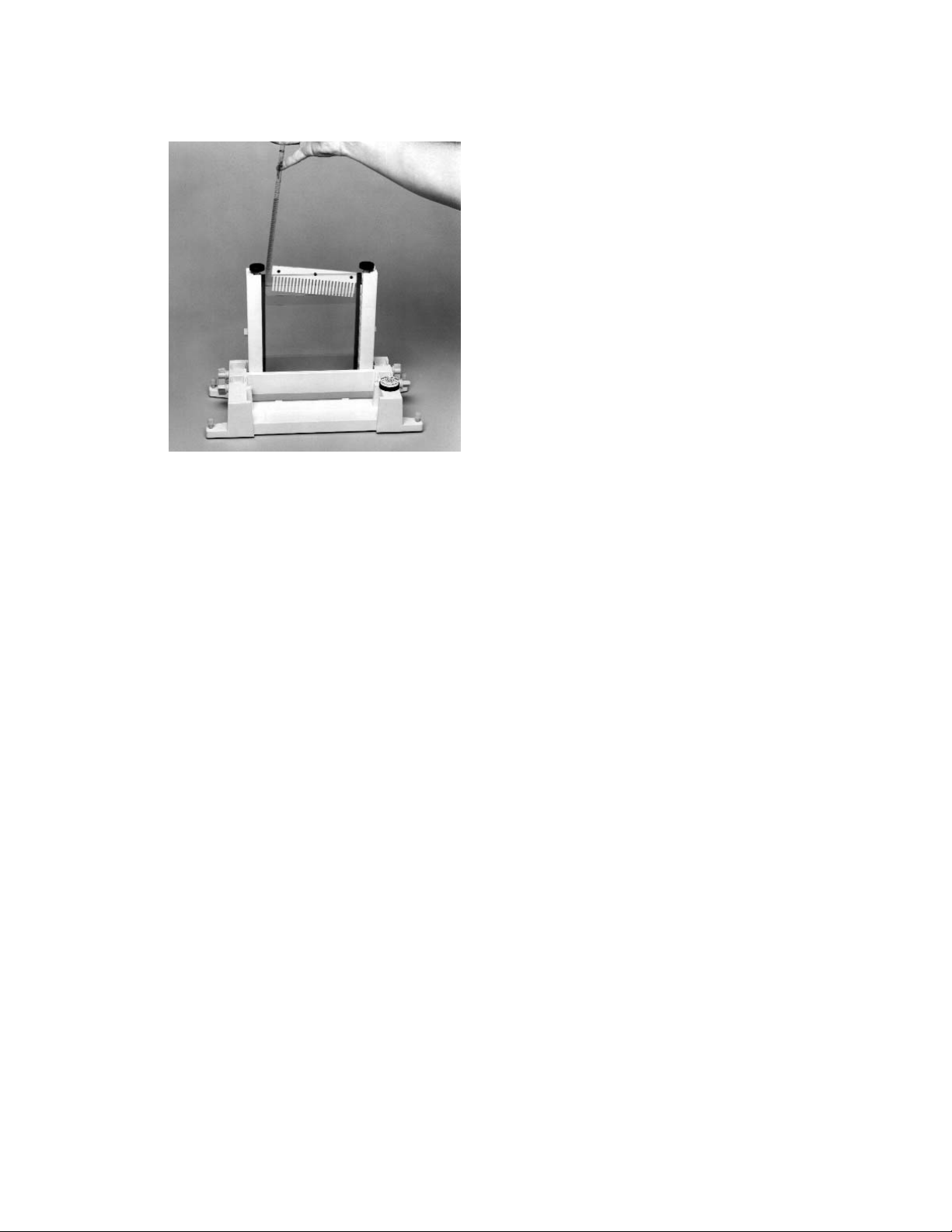
Fig. 6.6. Pouring a SSCP gel.
4. Pour or pipette the gel solution into the sandwich until it covers the wells of the comb.
Straighten the comb to the desired well depth. Add more solution if needed.
5. Allow the gel to polymerize for about 60 minutes. After polymerization, remove the comb
by pulling it straight up slowly and gently.
6. Continue with Section 8 for electrophoresis.
Section 7
Protein Truncation Test
7.1 Introduction to PTT
Increasing numbers of genes with translation terminating mutations are being identified.
The Protein Truncation Test (PTT) is a mutation screening method that detects truncated
proteins after translation of the coding sequence.
7, 30
There are six steps associated with the
PTT assay. The first step is to amplify by PCR a template RNA sample. The second step
requires a reverse transcriptase reaction of the starting mRNA to make cDNA. The third
step amplifies the sequence of interest and incorporates a tailed primer sequence. This
tailed primer contains a T7 promoter and eukaryotic translation initiation sequence. These
sequences are needed for in vitro transcription and translation. The fourth step checks the
PCR product on an agarose gel for quality, size, and approximate quantity. In the fifth step,
the PCR products are transcribed with RNA polymerase and translated into peptides. There
are commercial kits that couple the transcription and translation reaction in one tube using
rabbit reticulocyte lysate (Promega). Detection of the translation products is done by adding
radiolabeled amino acids, typically 3H-Leucine or 35S-methionine, to the translation reaction.
The final step involves analyzing the translation products on an SDS-PAGE gel to determine
their length. The gel is normally treated with a fluorographic-enhancing reagent to reduce
the exposure time to X-ray film. Truncated proteins are identified by size differences when
compared to full-length control proteins.
61
Page 66

7.2 Reagent Preparation
The concentration and type of acrylamide to use varies for the sample being analyzed on
the DCode system, therefore, a 40% stock solution containing acrylamide and bis-acrylamide
(Bis) should be made. Reagents for casting and running PTT gels are included in the DCode
electrophoresis reagent kit for PTT, catalog number 170-9174.
For different percent crosslinking, use the equation below to determine the amount of Bis
to add. The example stock solution below is for an acrylamide/bis ratio of 37.5:1.
40% Acrylamide/Bis (37.5:1)
Reagent Amount
Acrylamide 38.93 g
Bis-acrylamide 1.07 g
dH2O to 100.0 ml
Filter through a 0.45 µ filter and store at 4°C.
Polyacrylamide gels are described with reference to two characteristics:
1) The total monomer concentration (%T)
2) The crosslinking monomer concentration (%C)
%T =
gm acrylamide + gm bis-acrylamide
x 100
total volume
%C =
gm bis-acrylamide
x 100
gm acrylamide + gm bis-acrylamide
1.5 M Tris-HCl, pH 8.8
Reagent Amount
Tris base 54.51 g
dH2O 150.0 ml
Adjust to pH 8.8 with 6 N HCl. Add dH2O to 300 ml.
0.5 M Tris-HCl, pH 6.8
Reagent Amount
Tris base 6.0 g
dH2O 60.0 ml
Adjust to pH 6.8 with 6 N HCl. Add dH2O to 100 ml and. Store at 4°C.
10% SDS
Reagent Amount
SDS 10.0 g
dH2O to 100.0 ml
Mix and store at room temperature.
10x Tris/Glycine/SDS Buffer, pH 8.3
Reagent Amount Final Concentration
Tris base 30.3 g 0.25 M
Glycine 144.1 g 1.92 M
SDS 10.0 g 1%
dH2O to 1,000 ml
Mix and store at room temperature.
62
Page 67

The table below provides the percentage acrylamide/bis needed for a particular size range.
Gel Percentage Base Pair Separation
7.5% 35–95 kD
10% 15–70 kD
15% 10–40 kD
Separating Gel–0.375 M Tris, pH 8.8
Reagent 7.5% 12% X%
40% Acrylamide/Bis 7.5 ml 12.0 ml (X%) = (A)*ml
1.5M Tris-HCl, pH 8.8 10.0 ml 10.0 ml 10.0 ml
10% SDS 0.4 ml 0.4 ml 0.4 ml
dH2O 17.2 ml 17.2 ml 29.2–(A)
*
10% Ammonium persulfate 400.0 µl 400.0 µl 400.0 µl
TEMED 40.0 µl 40.0 µl 40.0 µl
Total volume 40.0 ml 40.0 ml 40.0 ml
Degas for 15 minutes before adding TEMED and ammonium persulfate. Cast the gel immediately
after adding the TEMED and ammonium persulfate.
* The letter A designates the volume of 40% acrylamide/bis solution required to produce the specified percent of gel (X%).
4% Stacking Gel–0.125 M Tris, pH 6.8
Reagent Amount
40% Acrylamide/Bis 1.0 ml
0.5 M Tris-HCl, pH 6.8 2.5 ml
10% SDS 0.1 ml
dH2O 6.4 ml
10% Ammonium Persulfate 50.0 µl
TEMED 10.0 µl
Total volume 10.0 ml
Degas for 15 minutes before adding TEMED and ammonium persulfate. Cast the gel immediately
after adding the TEMED and ammonium persulfate.
Laemmli Sample Buffer
Reagent Amount Final Concentration
0.5 M Tris-HCl, pH 6.8 3.1 ml 62.5 mM
100% Glycerol 6.25 ml 25%
10% SDS 5.0 ml 2%
0.5% Bromophenol blue 0.5 ml 0.01%
dH2O 10.15 ml
Total volume 25.0 ml
Mix and store at 4°C. Before use add 10 µl ß-mercaptoethanol to 590 µl Laemmli buffer.
Dilute sample 1:2 with Laemmli buffer.
Coomassie Blue Stain
Reagent Amount Final Concentration
Coomassie Blue R-250 1.0 g 0.1%
Methanol 400 ml 40%
Acetic acid, glacial 100 ml 10%
dH2O 500 ml
Total volume 1,000 ml
Mix and store at room temperature.
63
Page 68

Coomassie Blue Destain
Reagent Amount Final Concentration
Methanol 400 ml 40%
Acetic acid, glacial 100 ml 10%
dH2O 500 ml
Total volume 1,000 ml
Mix and store at room temperature.
7.3 Gel Volumes
The table below provides the required volume for the gel size and spacer thickness.
Spacer Thickness 20 x 20 cm Gel
0.75 mm 30 ml
1.00 mm 40 ml
7.4 Sample Preparation
1. Dilute samples, controls, and protein marker (such as Bio-Rad pre-stained markers) 1:2
with Laemmli sample buffer.
Note: Add 10 µl b-mercaptoethanol to 590 µl Laemmli buffer just before use. This solution
is good for 1 day only.
2. Heat the samples at 95–100°C for 5 minutes.
64
Page 69
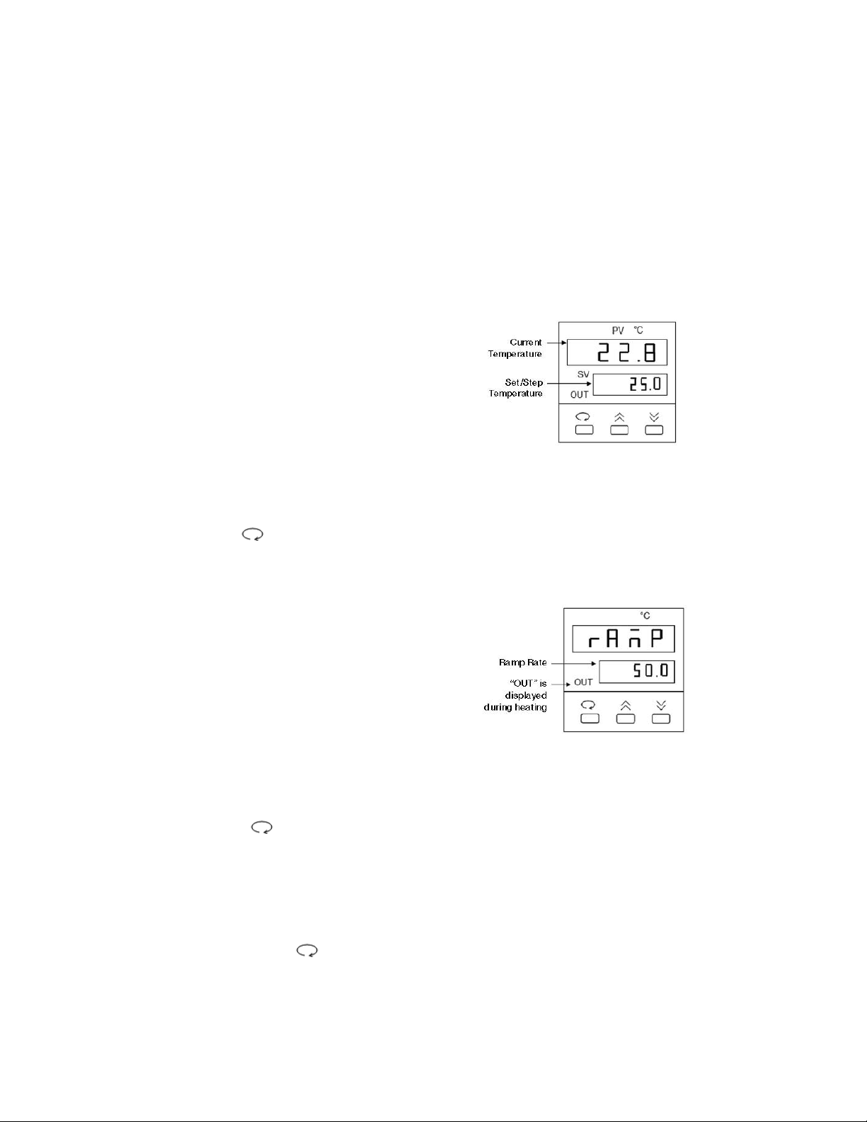
7.5 Temperature Controller
The temperature controller maintains the desired buffer temperature in the DCode system.
Turning on the Controller
Turn the controller on by pressing the power button and wait for the controller to
initialize. The controller will display the following screens in order:
• The program code
• The date code and serial code
• The hours used
• The temperature control screen (see Fig. 1).
The controller is now ready to be
programmed.
Setting the Set Temperature and Ramp Rate
1. From the temperature control screen,
use the arrow keys to adjust the Set
Temperature to your desired target
temperature in °C (Fig. 1)
2. Use the key to display the ramp
control screen. (Fig. 2.)
3. From the ramp control screen, use
the arrow keys to set the desired
temperature Ramp Rate in °C per hour.
Note that the maximum ramp rate for
the DCode is 50°C /hr. If the target
Ramp Rate is set using the controller
to higher than 50°C /hr the maximum
ramp rate of 50°C /hr will be used.
4. To toggle between the temperature control
screen and the ramp control screen, or to
review the set temperature and ramp rate,
press the key at any time
Note: Following programming by default the controller displays the Step Temperature rather
than the Set Temperature (see Fig 1. below). The step temperature is the next temperature
value the system will reach as it heats/cools to reach set temperature. To display the Set
Temperature press the key.
65
Fig. 1. Temperature Control Screen.
Fig. 2. Ramp Control Screen.
Page 70

7.6 Adding the Running Buffer
1. Remove and place the temperature control module on the DCode lid stand.
2. Add 2 or 7 L of running buffer to the electrophoresis tank.
Note: To improve heat dissipation during electrophoresis, 7 L of buffer can be used.
3. Place the temperature control module on the electrophoresis tank.
7.7 Assembling the PTT Gel Sandwich
For PTT gel formats, a 20 x 20 cm gel sandwich is used. To insure proper alignment,
make sure all plates and spacers are clean and dry before assembly. Use caution when
assembling the glass plate sandwiches. Wear gloves and eye protection at all times.
1. Assemble the gel sandwich on a clean surface. Lay the large rectangular plate down first,
then place the left and right spacers of equal thickness along the short edges of the larger
rectangular plate.
2. Place a short glass plate on top of the spacers so that it is flush with the bottom edge of
the long plate.
3. Loosen the single screw of each sandwich clamp by turning counterclockwise. Place each
clamp by the appropriate side of the gel sandwich with the locating arrows facing up and
toward the glass plates (Figure 7.2).
Fig. 7.2. Positioning glass plates, spacers, and clamps.
4. Grasp the gel sandwich firmly. Guide the left and right clamps onto the sandwich so that
the long and short plates fit the appropriate notches in the clamp (Figure 7.3). Tighten
the screws enough to hold the plates in place.
66
Page 71

Fig. 7.3. Attaching the clamps to the glass plate assembly.
5. Place the sandwich assembly in the alignment slot (the slot without cams) of the casting
stand with the short glass plate forward (Figure 7.4). Loosen the sandwich clamps and
insert an alignment card to keep the spacers parallel to the clamps.
Note: Always use the alignment slot and alignment card to set the spacers in place. Failure
to use these can result in gel leakage when casting, as well as buffer leakage during the
run.
6. Align the plates and spacers by simultaneously pushing inward on both clamps at the locating
arrows while pushing down on the spacers with your thumbs. Tighten both clamps just enough
to hold the sandwich in place. Pushing inward on both clamps at the locating arrows will insure
that the spacers and glass plates are flush against the sides of the clamps (Figure 7.4).
Fig. 7.4. Aligning spacers in the sandwich assembly.
67
Page 72

7. Remove the alignment card. Remove the sandwich assembly from the casting stand and
check that the plates and spacers are flush at the bottom. If they are not flush, realign the
sandwich and spacers for a good seal (repeat steps 5–7).
8. When a good alignment and seal are obtained, tighten the clamp screws until it is finger-tight.
7.8 Casting PTT Gels
1. Place the gray sponge onto the front casting slot. The camshafts on the casting stand
should have the handles pointing up and pulled out. Place the sandwich assembly on the
sponge with the shorter plate facing forward. When the sandwich is placed correctly, press
down on the sandwich and turn the handles of the camshaft down so that the cams lock
the sandwich in place.
2. PTT samples are typically run in a discontinuous Laemmli gel.31Discontinuous gels
consist of a resolving or separating (lower) gel and a stacking (upper) gel. The stacking
gel acts to concentrate large sample volumes.
3. Insert a comb into the assembled gel sandwich. With a marker pen, place a mark on the
glass plate 1–2 cm below the teeth of the comb. This will be the level to which the separat-
ing gel is poured. Remove the comb.
4. Into a 50 ml tube, add the required amount of solution for casting the lower or separating gel
(Section 7.2). Add a final concentration of 0.09% (v/v) each of ammonium persulfate and
TEMED solutions. Cap the tube and mix.
5. Pour or pipette the gel solution into the sandwich until the gel solution reaches the mark
on the glass plate.
6. Immediately overlay the monomer solution with water, water-saturated isobutanol, or
t-amyl alcohol. Isobutanol or t-amyl alcohol can be applied rapidly with a Pasteur pipet
and bulb because very little mixing will occur. If water is used, it must be applied with a
needle and syringe, using a steady, even rate of delivery to prevent mixing.
7. Allow the gel to polymerize for 60 minutes. Rinse the overlay solution completely with
distilled water. This is especially important with alcohol overlays. Do not allow alcohol to
remain on the gels more than 1 hour to prevent dehydration of the top of the gel.
8. Into a 50 ml tube, add the required amount of solution for casting the upper or stacking gel
(Section 7.2). Add a final concentration of 0.09% (v/v) each of ammonium persulfate and
TEMED solutions. Cap the tube and mix.
9. Insert a comb in the gel sandwich and tilt it so the teeth are at a slight angle. This will prevent
air from being trapped under the comb teeth when pouring the gel solution (Figure 7.5).
68
Page 73
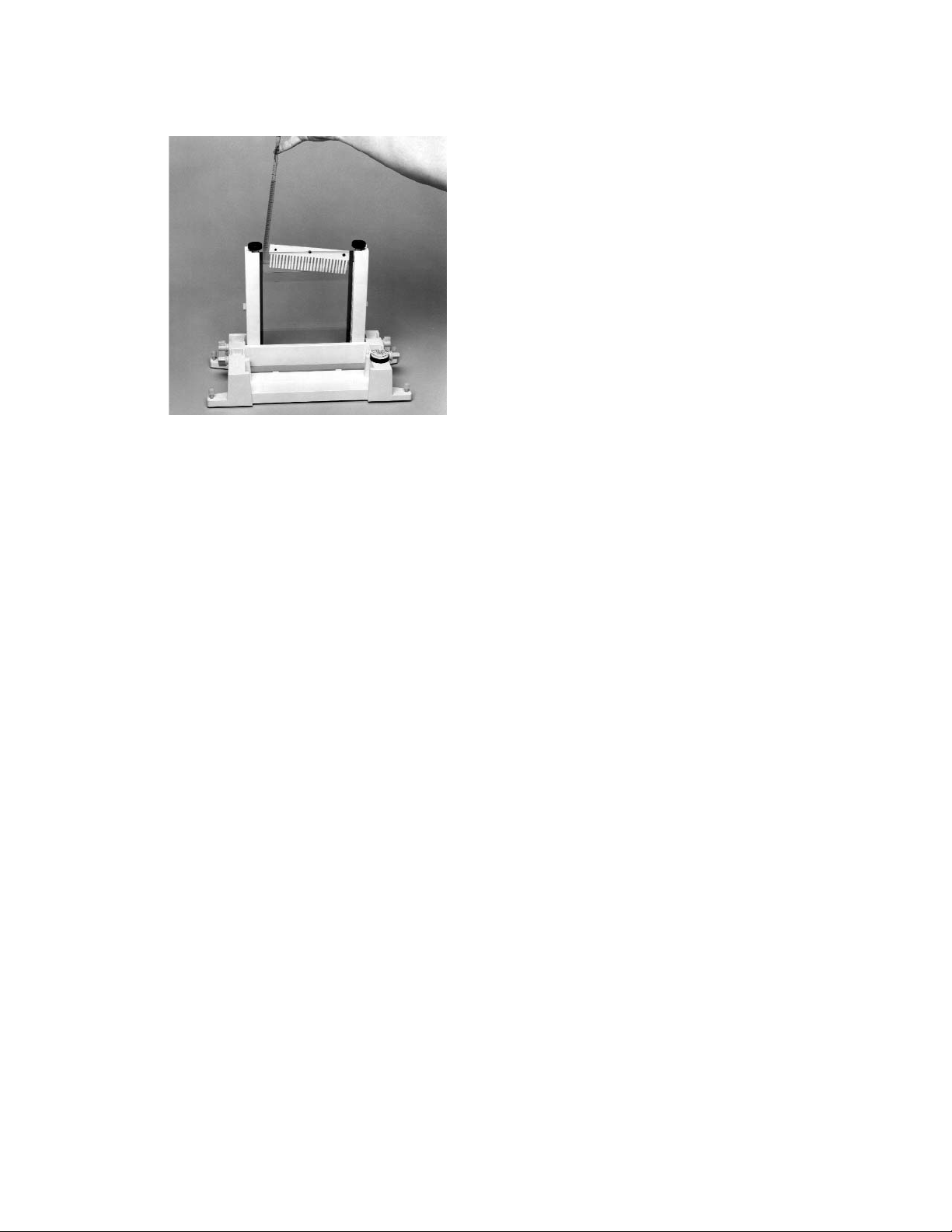
Fig. 7.5. Pouring a PTT gel.
10. Pour or pipette the gel solution into the sandwich until it covers the wells of the comb.
Straighten the comb to the desired well depth. Add more solution if needed.
11. Allow the gel to polymerize for about 60 minutes. After polymerization, remove the comb
by pulling it straight up slowly and gently.
12. Continue with Section 8 for electrophoresis.
Section 8
Electrophoresis
8.1 Assembling the Upper Buffer Chamber
1. Lay the inner core flat on a bench. Make sure the white U-shaped gasket on the inner core
is seated properly and clear of any particles that may cause leakage, such as residual gel
material.
2. After the gel has polymerized, release the gel sandwich from the casting stand by turning
the camshafts 180°, to the up position, and pulling them outward. Remove the sandwich
and the comb.
Note: To easily visualize the wells when loading the samples, use a permanent marker
to mark the wells.
3. With the short glass plate facing the core, position the gel sandwich so that the locating pins on
the core are fitted into the grooves on the outside surface of the sandwich clamps (Figure 8.1).
The gel sandwich should be positioned at an angle of 20° with the core. Keeping this angle
to a minimum will prevent distortion of the gasket while the sandwich slides into place.
Note: To help insure a good buffer seal, lubricate the entire front of the core gaskets
with water or running buffer prior to attaching the gel sandwich to the core. This will
allow the glass plate sandwich to slide onto the gasket properly.
4. With your fingers below the latch on the core and your thumbs resting on the bottom of the
sandwich clamps, gently push the gel sandwich down onto the core with one simple motion.
You should be able to hear a click. The upper edge of the short inner glass plate should be
seated against the notches of the U-shaped gasket and the tabs of each clamp should be
held securely against the latch assemblies on both sides of the core (Figure 8.1).
69
Page 74

Fig. 8.1. Attaching the sandwich assembly on to the core.
5. Turn the core to its other side and repeat steps 1–4 to attach the second gel sandwich.
Note: When the gel sandwich has been properly installed, the shorter inside glass plate
will be forced against the notch in the U-shaped gasket to create a leak-proof seal. Always
inspect the contact between the gasket and glass plate to make sure the glass plate is
seated against the notch in the gasket and is not resting above or below this notch.
Improper installation of the gel sandwich can result in buffer leakage during the run.
6. If only one gel is to be run, assemble a set of glass plates without the spacers. Place the
short glass plate on top of the long glass plate. Guide the left and right clamps onto the
sandwich so that the plates fit the appropriate notches in the clamp. Insure that the bottom
of the glass plates are flush. Tighten the screws enough to hold the plates in place. No
further alignment is necessary. Attach it to the other side of the core to form an upper chamber
dam.
7. Pour 350 ml of running buffer into the upper buffer chamber. At this point, check the integrity
of the upper buffer seal. If the buffer appears to be leaking, pour the running buffer into a
beaker, remove the gel sandwich assemblies (Section 8.4), re-lubricate the gasket, and
repeat steps 1–4.
DGGE, CDGE, and SSCP Gels
1. The electrophoresis tank should contain 7 L the appropriate running buffer.
2. When the running buffer has reached the desired temperature, turn the system off.
Disconnect the power cord.
3. Remove and place the temperature control module on the DCode lid stand. Place the
core and the attached gel assemblies into the buffer chamber by positioning the red
button towards the right hand side and the black button along the left hand side of the
system. Place the temperature control module on top of the electrophoresis tank.
Note: The core fits into the tank in one orientation only, allowing the core to lock in place.
4. Connect the power cord and turn the power, pump, and heater on. Remove the clear loading
lid and wash the wells with running buffer to remove any unpolymerized gel material/leached
denaturants from the wells. If necessary, add more buffer to the “max” line on the
electrophoresis tank. Place the clear loading lid back onto the temperature control module.
5. Allow the system to reach the set initial temperature before loading samples. This may take
10–15 minutes.
70
Page 75

TTGE Gels
1. The electrophoresis tank should contain 7 L of the appropriate running buffer.
2. When the running buffer has reached the desired temperature, turn the system off.
Disconnect the power cord.
3. Remove and place the temperature control module on the DCode lid stand. Place the core
and the attached gel assemblies into the buffer chamber by positioning the red button
towards the right hand side and the black button along the left hand side of the system.
Place the temperature control module on top of the electrophoresis tank.
Note: The core fits into the tank in one orientation only, allowing the core to lock in place.
4. Connect the power cord and turn power, pump and heater on. Remove the clear loading
lid and wash the wells with running buffer to remove any unpolymerized gel material/leached
denaturants from the wells. If necessary, add more buffer to the “max” line on the
electrophoresis tank. Place the clear loading lid back onto the temperature control module.
5. Allow the system to reach the set initial temperature before loading samples. This may take
10–15 minutes.
6. When the set initial temperature is reached, press the °C/RR button to select the ramp rate. Set
the desired ramp rate using the raise and lower buttons. Allow the heater to equilibrate to the
lower ramp rate for 5–10 minutes before loading samples. Press the °C/RR button to return to
the temperature readout.
Heteroduplex, CSGE, and PTT Gels
1. The electrophoresis tank should contain at least 2 L of the appropriate running buffer.
2. Remove and place the temperature control module on the DCode lid stand. Place the core
and the attached gel assemblies into the buffer chamber by positioning the red button
towards the right hand side and the black button along the left hand side of the system.
Place the temperature control module on top of the electrophoresis tank.
Note: The core fits into the tank in one orientation only, allowing the core to lock in place.
8.2 Sample Loading
1. Remove the clear loading lid. Wash the wells with running buffer to remove any unpoly-
merized gel material or denaturants in the wells.
2. Load the samples using a pipetman and a sequencing loading tip. Be careful not to pierce
the wells during sample delivery.
3. Place the clear loading lid on top of the temperature control module.
8.3 Running the Gel
1. Attach the electrical leads to a suitable DC power supply. Recommended power supply:
Bio-Rad’s Power Pac 300 or 3000.
DGGE, CDGE, and TTGE Gels
1. For DGGE and CDGE run the gel at 130 volts. Apply power to the DCode system and
begin electrophoresis. As a precaution, always set the voltage, current, and power limits
when possible.
Note: The voltage should not exceed 180 V, electrophoretic heating may affect results.
71
Page 76

2. For TTGE runs, set the desired final temperature and run the gel at 130 volts.
Note: The voltage should not exceed 150 V for TTGE runs, electrophoretic heating may
affect the temperature gradient.
Optional: If your power supply has a built-in timer, set the power supply timer to the
desired run time.
3. The run time should be determined empirically for each fragment being analyzed. As a
reference during electrophoresis, two marker dyes in the 2x gel loading dye can be used
to determine when to stop a DGGE and CDGE run. The dyes are bromophenol blue (dark
blue) and Xylene cyanol (light blue). For a TTGE run, the run time is dependent on the
temperature ramp rate. Refer to Section 4.3 for determining TTGE run conditions.
SSCP Gels
1. Run the gel at 20–40 W constant power for 2–6 hours or until desired resolution is achieved.
The run time should be determined empirically for each fragment being analyzed.
Note: Electrophoresis runs at high power settings (30–40 W) may generate gel heating
which causes the “smiling effect” (bands curve upward at both sides of the gel).
2. As a reference during electrophoresis, two marker dyes in the 2x SSCP gel loading dye can
be used to determine when to stop a run. The dyes are bromophenol blue (dark blue) and
Xylene cyanol (light blue).
Optional: When using radioactive samples, the pump may be turned off during
electrophoresis to reduce radioactive contamination.
3. Apply power to the DCode system and begin electrophoresis. As a precaution, always
set the voltage, current, and power limits when possible.
Heteroduplex and CSGE Gels
1. For heteroduplex analysis and CSGE, run the gel at 100 volts for 16–20 hours. The run
time should be determined empirically for each fragment being analyzed. CSGE gels
typically run between 1–2 mAmps. Check to insure the power supply you are using does
not shut off when the current is below 2 mAmps.
2. Begin electrophoresis. As a precaution, always set voltage, current, and power limits
when possible.
Note: The DCode system temperature control module is off for Heteroduplex and CSGE runs.
PTT Gels
1. It is recommended that gels be run under constant current conditions. For 1.0 mm thick
gels, run at 25–35 mAmps/gel for 45 minutes, then increase the current to 40–50
mAmps/gel. Run times are typically between 3 and 5 hours. Under constant current
conditions, voltage will gradually increase during the run.
Optional: When using radioactive samples, the pump should be turned off during
electrophoresis to reduce radioactive contamination.
2. Begin electrophoresis. As a precaution, always set voltage, current, and power limits
when possible.
Note: The DCode system temperature control module is off for PTT runs.
72
Page 77
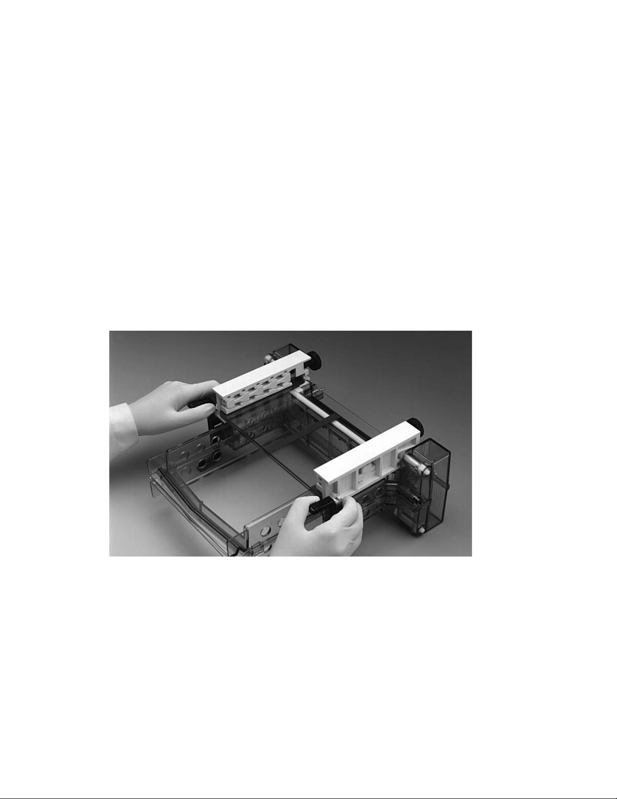
8.4 Removing the Gel
1. After electrophoresis is complete, turn the power supply and system (heater, pump, and
power) off. Disconnect the power cord and electrical leads. Allow the heater to cool for
approximately 1 minute in the buffer.
2. Remove the temperature control module and place it on the DCode lid stand.
Caution: The heater is still hot. Do not touch. Carefully pull the core out of the
electrophoresis tank. Pour off the upper buffer into the tank by tilting the core above and
over the chamber.
3. Lay the core and gel sandwiches on a padded surface to absorb buffer spills.
a. For 16 x 10 cm and 7.5 x 10 cm gels, remove the sandwich assembly with your thumb,
pushing on the latches on the core outward and your index finger pushing on the
sandwich clamp. Pull the sandwich assembly off the locating pins on the top of the core.
b. For 16 x 16 cm and 16 x 20 cm gels, remove the sandwich assembly with your index
fingers below the sandwich clamps and your thumbs resting on the latches on the
core. Gently remove the assembly by pulling up (in a manner opposite to the way it
was attached). Pull the sandwich assembly off the locating pins on the top of the core.
Fig. 8.2. Removing the sandwich assembly from the core.
4. Loosen the single screw of each clamp and remove the clamps from the sandwich.
Carefully pry off the shorter glass plate. Do not use a metal spatula to remove the glass
plate. This may chip or crack the plate.
5. Remove the spacers and cut one corner of the gel to distinguish between gels.
Note: If different buffers are used between runs it is advisable to rinse the pump with
distilled water. Place the DCode module on the DCode stand. Fill a 500 ml beaker with
distilled water and place it under the pump inlet tube. Place an empty beaker under the
pump outlet tube. Turn the pump on for 1–2 minutes.
73
Page 78

8.5 Staining and Photographing the Gel
DGGE, CDGE, TTGE, and Heteroduplex Gels
1. Remove the gel from the glass plate.
2. Place the gel into a dish containing 250 ml of running buffer and 25 µl of 10 mg/ml ethidium
bromide (50 µg/ml). Stain for 5–15 minutes.
2. After staining, carefully transfer the gel into a dish containing 250 ml of 1x running buffer.
Destain for 5–20 minutes.
3. Place the gel on a UV transilluminator and photograph (Gel Doc™1000 system catalog
number 170-7520 through 170-7527 or Bio-Rad's Polaroid Gel Documentation System,
catalog numbers 170-3742 through 170-3749).
SSCP Gels
1. Remove the gel from the glass plate. For radioactive SSCP gels, proceed to step 5.
Caution: Use caution when handling radioisotopes. Proper handling and disposal of
radioactive material should be followed.
2. Place the gel into a dish containing 250 ml of running buffer and 1:10,000 dilution SYBR
®
Green II (Molecular Probes, Inc.). Stain for about 30 minutes. The gel can also be stained
with Radiant™Red stain (Bio-Rad catalog number 170-3122). Place the gel into a dish
containing 250 ml of running buffer and 1:1,000 dilution Radiant Red stain. Stain for about
30 minutes.
3. After staining, carefully transfer the gel into a dish containing 250 ml of running buffer.
Destain for 30 minutes if needed.
4. Place the gel on a UV transilluminator and photograph.
5. Gels that have been labeled with radioisotopes must be autoradiographed or exposed to
a storage phosphor imaging screen (GS-525 Molecular Imager™screen). Carefully place
a 3MM Whatman®paper on top of the gel. Gently slide your hand across the paper to
adhere the gel to the paper and to remove any air bubbles. Flip the gel over and place a
Saran Wrap™plastic wrap evenly on top of the gel without creating any bubbles. This
helps to keep the gel intact and prevents any contamination to the gel dryer. Place the gel
on a gel dryer for about 60 minutes at 60°C.
6. Expose the gel to film or a phosphor imaging screen. Scan the imaging screen on a storage
phosphor imaging system (GS-525 Molecular Imager
™
system catalog number 170-7320
through 170-8305). Develop the film after proper exposure time.
PTT Gels
1. Remove the gel from the glass plate.
2. To visualize the protein standards, place the gel into a dish containing 250 ml of
Coomassie
®
blue stain. Stain for 20–30 minutes.
3. After staining, carefully transfer the gel into a dish containing 250 ml of Coomassie destaining
solution. Destain until the background disappears, usually about 1–3 hours.
4. Gels that have been labeled with radioisotopes must be autoradiographed or exposed to
a storage phosphor imaging screen (GS-525 Molecular Imager screen). Since
35
S or3H
are weak beta emitters and are typically used as a radioactive label, the gel should be
treated with a commercial fluorographic enhancing reagent to reduce the film exposure
time (i.e. Amplify™from Amersham). Fluorographic reagents are not needed if the
sample is exposed to a phosphor imaging screen.
74
Page 79

Caution: Use caution when handling radioisotopes. Proper handling and disposal of
radioactive material should be followed.
5. After the gel has been treated with a fluorographic reagent, carefully place the gel on a
3MM Whatman paper and remove any air bubbles. Place Saran Wrap evenly on top of the
gel without creating any bubbles. This helps to keep the gel intact and prevents any
contamination to the gel dryer. Place the gel in a gel dryer for about 60 minutes at 60°C.
6. Expose the gel to X-ray film or a phosphor imaging screen. Scan the imaging screen on
a storage phosphor imaging system.
Section 9
Troubleshooting
Always confirm that the line voltage is correct for the DCode system.
9.1 Equipment
Problem Cause Solution
Controller
No display with power on Burned out fuse Replace fuse located
near power cord
connection
Buffer not circulating Buffer level too low Add buffer to ‘Fill’
level
Pump clogged, not Call Bio-Rad
working
Cannot preheat buffer Buffer level too low Add buffer to ‘Fill’ level
Long preheat time Clear loading lid not Place clear loading lid on
on system system
Stir bar not functioning Broken belt on stirrer Replace belt
Stir bar interferes with Maximum thickness
gel sandwiches of gel is 1.5 mm
Stir bar not engaged Align stir bar in support
tank hole
Casting gels
Leaking during gel casting Improper assembly of Using the alignment
gel sandwich card, check that the
spacers and glass plate
bottom are flush prior to
pouring gel
Chipped glass plates Insure glass plates are
free of flaws. Use new set
of glass plates
75
Page 80

9.1 Equipment (continued)
Problem Cause Solution
Perpendicular gradient (DGGE only)
Glass plate cracked Excessive force at Apply only one turn
comb gasket to thumb gasket screw
after it touches glass
Gel solution leaks during casting Not sufficient pressure Make sure pressure
on comb gasket clamp screws are
turned two turns
Poor contact between Reassemble glass
comb gasket and plates as in Section
spacers 4.1. Visually confirm
contact at spacers and
comb gasket
Casting stand gasket Position gray gasket
positioned incorrectly so that it covers the entire
bottom section of the
glass plate
Wrong comb gasket Make sure correct
comb gasket is used
Misaligned comb gasket Insure that comb gasket
notches are against
spacer notches
Misaligned plates Pressure clamp may
force plates to shift if
sandwich clamps are not
tight. Insure that
sandwich clamps are
tightened
Misalignment of spacers Check alignment at
and glass plates bottom of glass plates,
using alignment slot on
casting stand
Damaged or dirty Replace spacers or
spacers and/or combs combs
Different thickness of Use spacers and comb
spacers and comb of same thickness
Dirty inlet fitting Replace fitting
or missing O-ring
Loose stopcock Tighten stopcock/inlet
port screw connection
No air vent plug Plug vent after casting gel
Damaged or non- Replace with Bio-Rad
Bio-Rad glass plates glass plates only
76
Page 81

9.2 Applications
Problem Solution
Perpendicular DGGE
Only a single band is seen Mix normal and mutant DNA samples
prior to loading well
Difficult to visualize hetero- 1. Increase amount of DNA (1–3 µg).
duplex and homoduplex 2. Use SYBR Green I dye agent
DNA bands (Molecular Probes, Inc.).
Unknown faint bands Impurity or non-specificity of PCR product
Poor gradient Insure that gradient delivery system is
working properly. See instructions
“S” curve appears to be shifted/cut 1. Increase upper gradient concentrations.
2. Level tilt rod after gel is cast.
Smear at top of gel Probably genomic DNA. This is OK
Parallel DGGE
Normal and mutant 1. Increase or decrease run time (time
course DNA unresolved run recommended).
2. Recalculate gradient range from
perpendicular gel or run a time course
gel.
Air bubbles in gel Clean glass plates
Fuzzy DNA bands Clean wells before use. Check for matching
comb and spacer thickness.
2. Let gel polymerize for at least
60 minutes.
Bands did not migrate far 1. Increase run time.
enough into gel 2. Decrease acrylamide concentration.
3. Decrease denaturant concentration.
DNA leaks between wells 1. Acrylamide not polymerized. Add more
TEMED and ammonium persulfate to
final concentration of 0.1%.
2. Degas acrylamide solution before
casting gel.
3. Let gel polymerize for at least
60 minutes.
4. Do not overload sample well. Reduce
sample volume.
Skewed or distorted bands, 1. Impurities in acrylamide. Filter before
or DNA spikes in gel use. Check shelf life date of acrylamide.
2. Carefully load DNA into wells. Do not
pierce or puncture wells.
77
Page 82

9.2 Applications (continued)
Problem Solution
CDGE
Normal and mutant Recalculate constant denaturant from a
DNA unresolved perpendicular or parallel DGGE gel
Air bubbles in gel Clean glass plates
Fuzzy DNA bands 1. Clean wells before use. Check for
matching comb and spacer thickness.
2. Let gel polymerize for at least 60 minutes.
Bands did not migrate far 1. Increase run time.
enough into gel 2. Re-check acrylamide concentration.
3. Re-check denaturant concentration.
DNA leaks between wells 1. Acrylamide not polymerized. Add more
TEMED and ammonium persulfate to
final concentration of 0.1%.
2. Degas acrylamide solution before
casting gel.
3. Let gel polymerize for at least 60 minutes.
4. Do not overload sample well. Reduce
sample volume.
Skewed or distorted bands, 1. Impurities in acrylamide. Filter before
use or DNA spikes in gel Check shelf life date of acrylamide
solution.
2. Carefully load DNA in wells. Do not
pierce or puncture the wells.
TTGE
Normal and mutant 1. Recalculate temperature gradient
from DNA unresolved MacMelt software.
2. Use a small temperature ramp rate
(rr = 1 or 2).
3. For narrow temperature ranges (< 6°C),
use a smaller ramp rate (i.e. 1°C/hr).
4. For large temperature ranges (> 9°C),
use larger ramp rate (i.e. 3°C/hr).
Air bubbles in gel Clean glass plates
Fuzzy DNA bands 1. Clean wells before use. Check for
matching comb and spacer thickness.
2. Let gel polymerize for at least
60 minutes.
Bands did not migrate far 1. Increase run time.
enough into gel 2. Decrease acrylamide concentration.
3. Increase temperature range and/or
run at lower temperatures.
78
Page 83

DNA leaks between wells 1. Acrylamide not polymerized. Add more
TEMED and ammonium persulfate to
final concentration of 0.1%.
2. Degas acrylamide solution before
casting gel.
3. Let gel polymerize for at least 60 minutes.
4. Do not overload sample well. Reduce
sample volume.
Skewed or distorted bands, 1. Impurities in acrylamide. Filter before
use. or DNA spikes in gel Check shelf life date of acrylamide.
2. Carefully load DNA into wells. Do not
pierce or puncture wells.
Heteroduplex Analysis
Normal and mutant 1. Optimize concentration of DEM.
DNA unresolved 2. Add 15% urea to gel.
3. Adjust voltage or run time so that
samples travel at least 15 cm from well.
Air bubbles in gel Clean glass plates
Fuzzy DNA bands 1. Clean wells before use. Check for
matching comb and spacer thickness.
2. Let gel polymerize for at least 60 minutes.
Bands did not migrate far 1. Increase run time.
enough into gel 2. Decrease acrylamide concentration.
3. Increase voltage.
DNA leaks between wells 1. Acrylamide not polymerized. Add more
TEMED and ammonium persulfate to
final concentration of 0.1%.
2. Degas acrylamide solution before casting
gel.
3. Let gel polymerize for at least 60 minutes.
4. Do not overload sample well. Reduce
sample volume.
Skewed or distorted bands, 1. Impurities in acrylamide. Filter before
or DNA spikes in gel use. Check shelf life date of
acrylamide.
2. Carefully load DNA in wells. Do not
pierce or puncture the wells.
SSCP
Normal and mutant 1. Optimize running temperature.
DNA unresolved 2. Add 5–10% glycerol to gel.
3. Reduce crosslinking of acrylamide and
bis.
4. Use different concentration of buffer.
79
Page 84

Buffer temperature does not 1. Use 50% ethylene glycol as chiller
coolant.reach set temperature
2. Insure that DCode temperature
controller is set at desired buffer
temperature.
3. Check that chiller is set to –20°C.
Air bubbles in gel Clean glass plates
Fuzzy DNA bands 1. Clean wells before use. Check for
matching comb and spacer thickness.
2. Let gel polymerize for at least 60 minutes.
Bands did not migrate far 1. Increase run time.
enough into gel 2. Decrease acrylamide concentration.
3. Increase voltage or power.
DNA leaks between wells 1. Acrylamide not polymerized. Add
more TEMED and ammonium
persulfate to final concentration of 0.1%.
2. Degas acrylamide solution before casting
gel.
3. Let gel polymerize for at least 60 minutes.
4. Do not overload sample well. Reduce
sample volume.
Skewed or distorted bands, 1. Impurities in acrylamide. Filter before use.
or DNA spikes in gel Check shelf life date of acrylamide.
2. Carefully load DNA in wells. Do not
pierce or puncture wells.
PTT
“Smile effect”–band pattern curves Decrease power setting, or fill lower chamber
upward at both sides of gelwith buffer up
to the "Max" setting on tank
Air bubbles in gel Clean glass plates
Fuzzy DNA bands 1. Clean wells before use. Check for
matching comb thickness and spacer
thickness.
2. Let gel polymerize for at least 60 minutes.
Bands did not migrate far 1. Increase run time.
enough into gel 2. Decrease acrylamide concentration.
3. Running buffer too concentrated.
Check buffer protocol.
4. Increase voltage or power.
Skewed or distorted bands 1. Acrylamide not polymerized. Add
more TEMED and ammonium
persulfate to final concentration of 0.1%.
2. Degas acrylamide solution before
casting gel.
3. Let gel polymerize for at least 60 minutes.
80
Page 85

Section 10
Specifications
Construction
Tank, core and clamps Tank: molded polycarbonate; Core: molded polysulfone;
Clamps: molded glass-filled polycarbonate
Lid Urethane or polycarbonate
Electrodes 0.010" diameter platinum
Electrical leads Polyurethane, copper conductor
Casting stand Able to cast two 16 x 20 cm, two 16 x 16 cm,
two 16 x 10 cm or one 7.5 x 10 cm gels per setup
simultaneously
Heater and control Temperature control (PID type) ± 0.5°C variation within
gel area, ± 0.5°C actual in the range of 45 to 70°C.Maximum set
temperature 70.5°C
Electrophoresis cooling Temperature control between 5°C–room temperature with
recommended chillers. Minimum temperature 5°C (SSCP system
only, external chiller required)
DC voltage limit 500 V DC
DC power limit 50 W
Gradient former Cast acrylic and acetal (DGGE system only)
Glass plates 20 x 22 cm (20 cm format), 16 x 20 cm (16 cm format),
10.2 x 20 cm (10 cm format)
Gel sizes 16 x 20 cm (max. two per run), 16 x 16 cm (max. two per run),
16 x 10 cm (max. two per run), 7.5 x 10 cm (max. four per run)
Spacers available 0.75, 1.0 and 1.5 mm
Combs 16 well comb (compatible with 8 well multi-channel
pipettor), 20 well comb, 25 well comb and 1 well comb
(Prep comb for perpendicular gradient gels). Optional can
use combs from PROTEAN
®
II xi system
AC Power Requirements
170-9080/9083/9086/9089 AC power input: 120 VAC 47–63 Hz, 5 A slow blow fuse
170-9092/9095/9098/9102
170-9082/9085/9088/9091 AC power input: 100 VAC 47–63 Hz, 5 A slow blow fuse
170-9094/9097/9100/9104
170-9081/9084/9087/9090 AC power input: 220–240 VAC 47–63 Hz, 2.5 A slow blow fuse
170-9093/9096/9099/9103
DC Power Requirements
External DC voltage power supply. This power supply must be ground isolated in such a way that the
DC voltage output floats with respect to ground.
Maximum voltage limit 500 VDC
Maximum power limit 50 W
Size and Weight
Overall size Lid and tank assembly: 39 cm (L) x 20 cm (W) x 42 cm (H)
Shipping weight 16 Kg
Environmental Requirements
Storage environment 0–70°C, humidity 0–95% (non-condensing)
Operating environment 0–35°C, humidity 0–95%
Regulatory
Meets requirements of EN61010-1.
81
Page 86

Section 11
Maintenance
Maintenance of Equipment
DCode system with lid Remove core and clamps from tank. Replace assembly
buffer inside tank with distilled water, turn pump on for
1–2 minutes to rinse pump. Remove water from tank.
Core, cell, clamps Rinse thoroughly with distilled water after use.
Glass plates, spacers, combs Wash with a laboratory detergent (catalog #161-0722) then
rinse with distilled water.
Always inspect the DCode tank, cable, and whole system. Replace any damaged
components before use. Damaged parts are to be repaired by Bio-Rad trained personnel
with Bio-Rad approved components only.
The controller retains its tuning parameters in non-volatile memory for 10 years without power.
Section 12
References
1. Orrita, M., Iwahana, H., Kanazawa, H., Hayashi, K., and Sekiya, T., Proc. Natl. Acad. Sci., 86, 2766–2770 (1989).
2. Fischer, S. and Lerman, L., Proc. Natl. Acad. Sci., 80, 1579–1583 (1983).
3. Ganguly, A. and Prockop, D., Nucleic Acids Res., 18, 3933–3939 (1990).
4. Cotton, R., Rodrigues, N., and Campbell, R., Proc. Natl. Acad. Sci., 85, 4397–4401 (1988).
5. Myers, R., Larin, Z., and Maniatis, T., Science, 230, 1242–1246 (1985).
6. Nagamine, C., Chan, K., and Lau, Y., Am. J. Hum. Genet., 45, 337–339 (1989).
7. Roest, P., Roberts, R., Sugino, S., Van Ommen, G., and Den Dunnen, J., Hum. Mol. Genet., 2, 1719–1721 (1993).
8. Yoshino, K., Nishigaki, K., and Husimi, Y., Nucleic Acids Res., 19, 3153 (1991).
9. Myers, R., Maniatis, T., and Lerman, L., Methods Enzymol., 155, 501–527 (1987).
10. Costes, B., Girodon, E., Ghanem, N., Chassignol, M., Thuong, N., Dupret, D., and Goossens, M., Hum. Mol. Genet., 2, 393–397 (1993).
11. Smith-Sorensen, B., Hovig, E., Andersson, B., and Borresen, A., Mutat. Res., 269, 41–53 (1992).
12. Lerman, L., Fischer, S., Hurley, I., Silverstein, K., and Lumelsky, N., Ann. Rev. Biophys. Bioeng., 13, 399–423 (1984).
13. Hovig, E., Smith-Sorensen, B., Uitterlinden, A., and Borresen, A., Pharmacogenetics, 2, 317–328 (1992).
14. Yoshino, K., Nishigaki, K., and Husimi, Y., Nucl. Acids Res., 19, 3153 (1991).
15. Wiese, U., Wulfert, M., Prusiner, S., B., and Riesner, D., Electrophoresis, 16, 1851–1860 (1995).
16. White, M., Carvalho, M., Derse, D., O’Brien, S., and Dean, M., Genomics, 12, 301–306 (1992).
17. Glavac, M., Glavac, D., and Dean, M., Hum. Mol. Genet., 3, 801–807 (1994).
18. Keen, J., Lester, D., Inglehearn, C., Curtis, A., and Bhattacharyya, S., Trends Genet., 7, 5 (1991).
19. Ganguly, A., Rock, M., and Prockop, D., Proc. Natl Acad. Sci., 90, 10325–10329 (1993).
20. Williams, C., Rock, M., Considine, E., McCarron, S., Gow, P., Ladda, R., McLain, D., Michels, V., Murphy, W., Prockop, D.,
and Ganguly, A., Hum. Mol. Genet., 4, 309–312 (1995).
21. Laing, T., and Gatti, R., personal communication (1996).
22. Sekiya, T., Technologies for detection of DNA Damage and Mutations, chapter 21, Plenum Press, New York, 281–290 (1996).
23. Spinardi, L., Mazars, R., and Theillet, C., Nucl. Acids Res., 19, 4009 (1991).
24. Hongyo, T., Buzard, G., Calvert, R., and Weghorst, C., Nucl. Acids Res., 21, 3637–3642 (1993).
25. Cotton, R., Mutat. Res., 285 (3), 813–826 (1992).
26. Glavac, D., and Dean, M., Hum. Mutation, 2, 404–414 (1993).
27. Hayashi, K., Laboratory Protocols for Mutation Detection, Oxford University Press, 14–22 (1996).
28. Prosser, J., Tibtech, 11, 238–247 (1993).
29. Grompe, M., Nature Genetics, 5, 111–117 (1993).
30. Den Dunnen, J. T., Roest, P., Van Der Luijt, R., and Hogervorst, F., Technologies for Detection of DNA Damage and Mutations,
edited by Gerd P. Pfeifer, Plenum Press 1996, p. 323–341.
31. Laemmli, U.K., Nature, 227, 680–685 (1970).
32. Gelfi, C., Righetti, P., Cremonesi, L., and Ferrari, M., Electrophoresis, 15, 1506–1511 (1994).
33. Steger, G., Nucleic Acids Res., 22, 2760–2768 (1994).
34. Myers, R., Fischer, S., Lerman, L., and Maniatis, T., Nucl. Acids Res., 13, 3131–3145 (1985).
82
Page 87

Section 13
Systems, Accessories, and Reagents for Mutation
Detection Electrophoresis
For complete ordering information for DCode accessories, electrophoresis reagents, and
control kits, request bulletin 2100.
Catalog
Number Product Description
DCode Universal Mutation Detection Systems
170-9080 DCode System for DGGE, 16 cm, 120 V, includes electrophoresis/
temperature control module, sandwich core, DGGE kit for 16 cm gel casting
(2 sets of plates, 2 sets of clamps and 1 mm spacers, two 1 mm one well
prep combs, comb gasket), all parts required to cast gradient gels, Model
475 Gradient Former, control reagents for DGGE
170-9081 DCode System for DGGE, 16 cm, 220/240 V
170-9082 DCode System for DGGE, 16 cm, 100 V
170-9083 DCode System for DGGE, 10 cm, 120 V, includes electrophoresis/
temperature control module, sandwich core, DGGE kit for 10 cm gel casting
(2 sets of plates, 2 sets of clamps and 1 mm spacers, two 2-well 1 mm
prep combs, comb gasket), all parts required to cast gradient gels, Model
475 Gradient Former, control reagents for DGGE
170-9084 DCode System for DGGE, 10 cm, 220/240 V
170-9085 DCode System for DGGE, 10 cm, 100 V
170-9086 DCode System for CDGE, 120 V, includes electrophoresis/temperature
control module, sandwich core, CDGE kit for 16 cm gel casting (2 sets of 16 cm
plates, 2 sets of 1 mm spacers, two 20-well 1 mm combs), control reagents
for CDGE
170-9087 DCode System for CDGE, 220/240 V
170-9088 DCode System for CDGE, 100 V
170-9089 DCode System for TTGE, 120 V, includes electrophoresis/temperature
control module, sandwich core, TTGE kit for 16 cm gel casting (2 sets of
16 cm plates, 2 sets of 1 mm spacers, two 20-well 1 mm combs), control
reagents for TTGE
170-9090 DCode System for TTGE 220/240 V
170-9091 DCode System for TTGE 100 V
170-9092 DCode System for SSCP, 120 V, includes electrophoresis temperature
control module, sandwich core, SSCP kit for gel casting (2 sets of 20 cm
plates, 2 sets 0.75 mm spacers, two 20-well 0.75 mm thick combs), elec-
trophoresis cooling tank for use with external cooling bath, control reagents
for SSCP
170-9093 DCode System for SSCP, 220/240 V
170-9094 DCode System for SSCP, 100 V
170-9095 DCode System for Heteroduplex Analysis, 120 V, includes electrophoresis/
temperature control module, sandwich core, heteroduplex kit for gel casting
(2 sets of 20 cm plates, 2 sets of 0.75 mm spacers, two 20-well 0.75 mm thick
combs), control reagents for heteroduplex analysis
170-9096 DCode System for Heteroduplex Analysis, 220/240 V
83
Page 88

Catalog
Number Product Description
170-9097 DCode System for Heteroduplex Analysis, 100 V
170-9098 DCode System for PTT, 120 V, includes electrophoresis/temperature control
module, sandwich core, PTT kit for gel casting (2 sets of 20 cm plates, 2 sets
of 1 mm spacers, two 20-well 1 mm thick combs)
170-9099 DCode System for PTT, 220/240 V
170-9100 DCode System for PTT, 100 V
170-9102 Complete DCode System, 120 V, includes electrophoresis/temperature
control module with cooling tank, sandwich core, Model 475 Gradient Former
with all accessories required to cast gradient gels, MacMelt software, control
reagents for DGGE/CDGE/TTGE, SSCP, PTT, and HA, plates, combs and
spacers to cast 1 mm and 0.75 mm thick 10, 16 and 20 cm gels.
170-9103 Complete DCode System, 220/240 V
170-9104 Complete DCode System, 100 V
DCode Accessories
170-9125 DGGE Kit, 16 cm, includes 2 sets of 16 cm plates, 2 sets of 1 mm spacers,
two 1-well 1 mm prep combs, sandwich clamps, pressure clamp, comb gasket
and holder, fittings required for gradient gel casting
170-9126 DGGE Kit, 10 cm, includes 2 sets of 10 cm plates, 2 sets of 1 mm spacers,
two 2-well 1 mm prep combs, sandwich clamps, pressure clamp, comb gasket
and holder, fittings required for gradient gel casting
170-9127 CDGE /TTGE Kit, includes 2 sets of 16 cm plates, 2 sets of 1 mm spacers,
two 20-well 1 mm combs, sandwich clamps
170-9128 Complete SSCP Kit, includes electrophoresis cooling tank for use with
external chiller, 2 sets of 20 cm plates, 2 sets of 0.75 mm spacers, two
20-well 0.75 mm combs, sandwich clamps
170-9129 Basic SSCP Kit, 2 sets of 20 cm plates, 2 sets of 0.75 mm spacers, two
20-well 0.75 mm combs, sandwich clamps
170-9130 Heteroduplex Kit, 2 sets of 20 cm plates, 2 sets of 0.75 mm spacers, two
20-well 0.75 mm combs, sandwich clamps
170-9131 PTT Kit, 2 sets of 20 cm plates, 2 sets of 1 mm spacers, two 25-well 1 mm
thick combs, sandwich clamps
170-9034 MacMelt Software
170-9042 Model 475 Gradient Former, includes cam-operated manual gradient
former, 2 each of 10 and 30 ml syringes, and all accessories required to
cast gradient gels
170-9140 Electrophoresis Cooling Tank, for use with external laboratory recirculating
chiller
84
Page 89

DCode Control and Electrophoresis Reagents
170-9150 DCode Control Reagent Kit for DGGE/CDGE/TTGE, includes primers
(one GC-clamped) and DNA templates for production of wild-type and
mutant DNA
170-9151 DCode Control Reagent Kit for SSCP, includes primers and DNA
templates for production of wild-type and mutant DNA
170-9152 DCode Control Reagent Kit for heteroduplex analysis, includes
homoduplex and heteroduplex DNA in 1x loading buffer
170-9170 DCode Electrophoresis Reagent Kit for DGGE/CDGE, includes 500 ml
40% acrylamide/bis solution(37.5:1), 250 g urea, 225 ml 100% formamide
(deionized), 2 x 1 liter 50x TAE buffer, 10 ml of 10 mg/ml EtBr, 1 ml of 2x gel
loading dye, 10 ml DCode dye solution, 5 ml TEMED, 10 g ammonium
persulfate
170-9171 DCode Electrophoresis Reagent Kit TTGE, includes 500 ml 40%
acrylamide/bis solution(37.5:1), 1 kg urea, 2 x 1 liter 50x TAE buffer, 10 ml
of 10mg/ml EtBr, 1 ml of 2x Gel loading dye, 5 ml TEMED, 10 g
ammonium persulfate
170-9172 DCode Electrophoresis Reagent Kit for SSCP, includes 500 ml 40%
acrylamide solution, 500 ml 2% bis solution, 100 ml of glycerol, 6 x 1 liter
10x TBE buffer, 2x SSCP gel loading dye, 5 ml TEMED, 10 g ammonium
persulfate
170-9173 DCode Electrophoresis Reagent Kit for Heteroduplex Analysis, includes
250 ml 2x DEM solution, 250 g urea, 6 x l liter 10x TBE, 2x gel loading dye,
10 ml of 10 mg/ml EtBr solution, 5 ml TEMED, 10 g ammonium persulfate
170-9174 DCode Electrophoresis Reagent Kit for PTT, includes 500 ml 40%
acrylamide/bis (37.5:1), 2 x 1 liter 10x Tris/Glycine/SDS buffer, 30 ml
Laemmli sample buffer, 500 g Tris base, 25 ml 2-mercaptoethanol, 250 ml
10% SDS, 10 g ammonium persulfate, 5 ml TEMED
858687
Page 90

Page 91

Page 92

Bio-Rad
M1709080 Rev D
Laboratories, Inc.
Life Science
Group
Bulletin 0000 Rev A US/EG
Web site www.bio-rad.com USA 800 4BIORAD Australia 61 02 9914 2800 Austria 01 877 89 01 Belgium 09 385 55 11 Brazil 55 21 3237 9400
Canada 905 364 3435 China 86 21 6426 0808 Czech Republic 420 241 430 532 Denmark 44 52 10 00 Finland 09 804 22 00
Germany 089 318 84 0 Greece 30 210 777 4396 Hong Kong 852 2789 3300 Hungary 36 1 455 8800 India 91 124 4029300 Israel 03 963 6050
Italy 39 02 216091 Japan 03 6361 7000 Korea 82 2 3473 4460 Mexico 52 555 488 7670 The Netherlands 0318 540666 New Zealand 0508 805 500
Norway 23 38 41 30 Poland 48 22 331 99 99 Portugal 351 21 472 7700 Russia 7 495 721 14 04 Singapore 65 6415 3188 South Africa 27 861 246 723
Spain 34 91 590 5200 Sweden 08 555 12700 Switzerland 061 717 95 55 Taiwan 886 2 2578 7189 United Kingdom 020 8328 2000
France 01 47 95 69 65
00-0000 0000 Sig 0308
 Loading...