


 Loading...
bintec elmeg GmbH |
Manual |
|
|
Manual bintec Next Generation WLAN
Reference
Copyright© Version 9.1.12 (3672), 2015 bintec elmeg GmbH
bintec Next Generation WLAN |
1 |
|
|
Manual |
bintec elmeg GmbH |
|
|
Legal Notice
Warranty
This publication is subject to change.
bintec elmeg GmbH offers no warranty whatsoever for information contained in this manual. bintec elmeg GmbH is not liable for any direct, indirect, collateral, consequential or any other damage connected to the delivery, supply or use of this manual.
Copyright © bintec elmeg GmbH.
All rights to the data included, in particular the right to copy and propagate, are reserved by bintec elmeg GmbH.
2 |
bintec Next Generation WLAN |
|
|
bintec elmeg GmbH |
Table of Contents |
|
|
Table of Contents
Chapter 1 |
Installation. . . . . . . . . . . . . . . . . . . . . . . . . . . . |
1 |
1.1 |
bintec W1001n, W1003n, W2003n, W2003n-ext and W2004n . . . . . . |
1 |
1.1.1Setting up and connecting . . . . . . . . . . . . . . . . . . . . . . 1
1.1.2 |
Connectors . . . . . . . . . . . . . . . . . . . . . . . . . . . . 4 |
1.1.3LEDs . . . . . . . . . . . . . . . . . . . . . . . . . . . . . . . 5
1.1.4 |
Scope of supply . . . . . . . . . . . . . . . . . . . . . . . . . . 6 |
1.1.5General Product Features . . . . . . . . . . . . . . . . . . . . . . 7
1.1.6 |
Reset . . . . . . . . . . . . . . . . . . . . . . . . . . . . . . . 9 |
1.2bintec WI1003n. . . . . . . . . . . . . . . . . . . . . . . . . . 10
1.2.1Setting up and connecting . . . . . . . . . . . . . . . . . . . . . 10
1.2.2 |
Connectors . . . . . . . . . . . . . . . . . . . . . . . . . . . 12 |
1.2.3LEDs . . . . . . . . . . . . . . . . . . . . . . . . . . . . . . 12
1.2.4 |
Scope of supply . . . . . . . . . . . . . . . . . . . . . . . . . 13 |
1.2.5General Product Features . . . . . . . . . . . . . . . . . . . . . 13
1.2.6 |
Reset . . . . . . . . . . . . . . . . . . . . . . . . . . . . . . |
15 |
1.3 |
bintec WO1003n and bintec WO2003n . . . . . . . . . . . . . . . |
15 |
1.3.1Setting up and connecting . . . . . . . . . . . . . . . . . . . . . 15
1.3.2 |
Connectors . . . . . . . . . . . . . . . . . . . . . . . . . . . 18 |
1.3.3LEDs . . . . . . . . . . . . . . . . . . . . . . . . . . . . . . 19
1.3.4 |
Scope of supply . . . . . . . . . . . . . . . . . . . . . . . . . 20 |
1.3.5General Product Features . . . . . . . . . . . . . . . . . . . . . 20
1.3.6 |
Reset . . . . . . . . . . . . . . . . . . . . . . . . . . . . . . |
22 |
1.4 |
Cleaning . . . . . . . . . . . . . . . . . . . . . . . . . . . . |
22 |
1.5 |
Pin Assignments . . . . . . . . . . . . . . . . . . . . . . . . . |
22 |
1.5.1Ethernet interface. . . . . . . . . . . . . . . . . . . . . . . . . 22
1.5.2 |
Power Connector . . . . . . . . . . . . . . . . . . . . . . . . . |
23 |
1.6 |
Frequencies and channels . . . . . . . . . . . . . . . . . . . . . |
24 |
1.7 |
Support information . . . . . . . . . . . . . . . . . . . . . . . . |
24 |
bintec Next Generation WLAN |
i |
|
|
Table of Contents |
bintec elmeg GmbH |
|
|
Chapter 2 |
Basic configuration . . . . . . . . . . . . . . . . . . . . . . |
25 |
2.1 |
Presettings . . . . . . . . . . . . . . . . . . . . . . . . . . . |
25 |
2.1.1 |
Preconfigured data . . . . . . . . . . . . . . . . . . . . . . . . |
25 |
2.1.2 |
Software update . . . . . . . . . . . . . . . . . . . . . . . . . |
26 |
2.2 |
System requirements . . . . . . . . . . . . . . . . . . . . . . . |
26 |
2.3 |
Preparation . . . . . . . . . . . . . . . . . . . . . . . . . . . |
27 |
2.3.1Gathering data . . . . . . . . . . . . . . . . . . . . . . . . . . 27
2.3.2 |
Configuring a PC . . . . . . . . . . . . . . . . . . . . . . . . . |
28 |
2.4 |
IP configuration. . . . . . . . . . . . . . . . . . . . . . . . . . |
29 |
2.5 |
Modify system password. . . . . . . . . . . . . . . . . . . . . . |
32 |
2.6 |
Setting up a wireless network . . . . . . . . . . . . . . . . . . . |
33 |
2.7Software Update . . . . . . . . . . . . . . . . . . . . . . . . . 34
Chapter 3 Access and configuration. . . . . . . . . . . . . . . . . . . 36
3.1Access Options. . . . . . . . . . . . . . . . . . . . . . . . . . 36
3.1.1 |
Access via LAN . . . . . . . . . . . . . . . . . . . . . . . . . 36 |
3.2Login . . . . . . . . . . . . . . . . . . . . . . . . . . . . . . 39
3.2.1 |
User names and passwords in ex works state . . . . . . . . . . . . |
39 |
3.2.2 |
Logging in for Configuration . . . . . . . . . . . . . . . . . . . . |
40 |
3.3Configuration options . . . . . . . . . . . . . . . . . . . . . . . 41
3.3.1GUI for advanced users . . . . . . . . . . . . . . . . . . . . . . 41
3.3.2 |
SNMP shell . . . . . . . . . . . . . . . . . . . . . . . . . . . 51 |
Chapter 4 Assistants . . . . . . . . . . . . . . . . . . . . . . . . . . . 52
Chapter 5 System Management . . . . . . . . . . . . . . . . . . . . . 53
5.1 |
Status . . . . . . . . . . . . . . . . . . . . . . . . . . . . . . |
53 |
ii |
bintec Next Generation WLAN |
|
|
bintec elmeg GmbH |
Table of Contents |
|
|
5.2Global Settings . . . . . . . . . . . . . . . . . . . . . . . . . . 56
5.2.1System . . . . . . . . . . . . . . . . . . . . . . . . . . . . . 56
5.2.2Passwords. . . . . . . . . . . . . . . . . . . . . . . . . . . . 58
5.2.3Date and Time . . . . . . . . . . . . . . . . . . . . . . . . . . 60
5.2.4 |
System Licences . . . . . . . . . . . . . . . . . . . . . . . . . |
65 |
5.3 |
Interface Mode / Bridge Groups . . . . . . . . . . . . . . . . . . |
67 |
5.3.1 |
Interfaces . . . . . . . . . . . . . . . . . . . . . . . . . . . . |
69 |
5.4Administrative Access . . . . . . . . . . . . . . . . . . . . . . . 73
5.4.1Access . . . . . . . . . . . . . . . . . . . . . . . . . . . . . 73
5.4.2 |
SSH . . . . . . . . . . . . . . . . . . . . . . . . . . . . . . 74 |
5.4.3SNMP. . . . . . . . . . . . . . . . . . . . . . . . . . . . . . 78
5.5 |
Remote Authentication . . . . . . . . . . . . . . . . . . . . . . 80 |
5.5.1RADIUS . . . . . . . . . . . . . . . . . . . . . . . . . . . . . 80
5.5.2TACACS+ . . . . . . . . . . . . . . . . . . . . . . . . . . . . 86
5.5.3 |
Options . . . . . . . . . . . . . . . . . . . . . . . . . . . . . |
89 |
5.6Configuration Access . . . . . . . . . . . . . . . . . . . . . . . 90
5.6.1Access Profiles . . . . . . . . . . . . . . . . . . . . . . . . . . 90
5.6.2 |
Users . . . . . . . . . . . . . . . . . . . . . . . . . . . . . . |
94 |
5.7 |
Certificates . . . . . . . . . . . . . . . . . . . . . . . . . . . |
98 |
5.7.1 |
Certificate List . . . . . . . . . . . . . . . . . . . . . . . . . . |
98 |
5.7.2CRLs . . . . . . . . . . . . . . . . . . . . . . . . . . . . . . 107
5.7.3 Certificate Servers . . . . . . . . . . . . . . . . . . . . . . . . 109
Chapter 6 |
Physical Interfaces . . . . . . . . . . . . . . . . . . . . . |
110 |
6.1 |
Ethernet Ports . . . . . . . . . . . . . . . . . . . . . . . . . . |
110 |
6.1.1 |
Port Configuration . . . . . . . . . . . . . . . . . . . . . . . . |
110 |
Chapter 7 |
LAN . . . . . . . . . . . . . . . . . . . . . . . . . . . . . |
112 |
7.1 |
IP Configuration . . . . . . . . . . . . . . . . . . . . . . . . . |
112 |
bintec Next Generation WLAN |
iii |
|
|
Table of Contents |
bintec elmeg GmbH |
|
|
7.1.1Interfaces . . . . . . . . . . . . . . . . . . . . . . . . . . . . 112
7.2VLAN . . . . . . . . . . . . . . . . . . . . . . . . . . . . . . 116
7.2.1 |
VLANs . . . . . . . . . . . . . . . . . . . . . . . . . . . . . |
118 |
7.2.2 |
Port Configuration . . . . . . . . . . . . . . . . . . . . . . . . |
119 |
7.2.3Administration . . . . . . . . . . . . . . . . . . . . . . . . . . 120
Chapter 8 Wireless LAN . . . . . . . . . . . . . . . . . . . . . . . . 121
8.1WLAN. . . . . . . . . . . . . . . . . . . . . . . . . . . . . . 122
8.1.1Radio Settings . . . . . . . . . . . . . . . . . . . . . . . . . . 122
8.1.2 |
Wireless Networks (VSS) . . . . . . . . . . . . . . . . . . . . . 132 |
8.1.3Client Link . . . . . . . . . . . . . . . . . . . . . . . . . . . . 141
8.1.4 |
Bridge Links . . . . . . . . . . . . . . . . . . . . . . . . . . . 145 |
8.2Administration . . . . . . . . . . . . . . . . . . . . . . . . . . 146
8.2.1Basic Settings . . . . . . . . . . . . . . . . . . . . . . . . . . 146
Chapter 9 |
Wireless LAN Controller . . . . . . . . . . . . . . . . . . |
148 |
9.1 |
Wizard . . . . . . . . . . . . . . . . . . . . . . . . . . . . . |
148 |
9.1.1 |
Basic Settings . . . . . . . . . . . . . . . . . . . . . . . . . . |
149 |
9.1.2Radio Profile . . . . . . . . . . . . . . . . . . . . . . . . . . . 150
9.1.3Wireless Network . . . . . . . . . . . . . . . . . . . . . . . . . 150
9.1.4Start automatic installation . . . . . . . . . . . . . . . . . . . . . 152
9.2Controller Configuration . . . . . . . . . . . . . . . . . . . . . . 154
9.2.1General . . . . . . . . . . . . . . . . . . . . . . . . . . . . . 154
9.3 |
Slave AP configuration . . . . . . . . . . . . . . . . . . . . . . |
156 |
9.3.1 |
Slave Access Points . . . . . . . . . . . . . . . . . . . . . . . |
157 |
9.3.2 |
Radio Profiles . . . . . . . . . . . . . . . . . . . . . . . . . . |
161 |
9.3.3 |
Wireless Networks (VSS) . . . . . . . . . . . . . . . . . . . . . |
168 |
9.4Monitoring . . . . . . . . . . . . . . . . . . . . . . . . . . . . 176
9.4.1WLAN Controller . . . . . . . . . . . . . . . . . . . . . . . . . 177
9.4.2 |
Slave Access Points . . . . . . . . . . . . . . . . . . . . . . . 178 |
iv |
bintec Next Generation WLAN |
|
|
bintec elmeg GmbH |
|
|
|
|
|
|
|
|
|
|
|
|
|
|
|
|
|
|
|
|
Table of Contents |
|
|
|
|
|
|
|
|
|
|
|
|
|
|
|
|
|
|
|
|
|
|
|
|
9.4.3 |
Active Clients . . . . . |
. |
. |
. |
. |
. |
. |
. |
. |
. |
. |
. |
. |
. |
. |
. |
. |
. |
. |
. |
. . |
180 |
9.4.4 |
Wireless Networks (VSS) |
. |
. |
. |
. |
. |
. |
. |
. |
. |
. |
. |
. |
. |
. |
. |
. |
. |
. |
. |
. . |
182 |
9.4.5 |
Client Management . . . |
. |
. |
. |
. |
. |
. |
. |
. |
. |
. |
. |
. |
. |
. |
. |
. |
. |
. |
. |
. . |
182 |
9.5 |
Neighbor Monitoring . . |
. |
. |
. |
. |
. |
. |
. |
. |
. |
. |
. |
. |
. |
. |
. |
. |
. |
. |
. |
. . |
183 |
9.5.1 |
Neighbor APs . . . . . |
. |
. |
. |
. |
. |
. |
. |
. |
. |
. |
. |
. |
. |
. |
. |
. |
. |
. |
. |
. . |
183 |
9.5.2 |
Rogue APs . . . . . . |
. |
. |
. |
. |
. |
. |
. |
. |
. |
. |
. |
. |
. |
. |
. |
. |
. |
. |
. |
. . |
184 |
9.5.3 |
Rogue Clients . . . . . |
. |
. |
. |
. |
. |
. |
. |
. |
. |
. |
. |
. |
. |
. |
. |
. |
. |
. |
. |
. . |
185 |
9.6 |
Maintenance . . . . . . |
. |
. |
. |
. |
. |
. |
. |
. |
. |
. |
. |
. |
. |
. |
. |
. |
. |
. |
. |
. . |
186 |
9.6.1 |
Firmware Maintenance . |
. |
. |
. |
. |
. |
. |
. |
. |
. |
. |
. |
. |
. |
. |
. |
. |
. |
. |
. |
. . |
187 |
Chapter 10 |
Networking . . . . . |
. |
. |
. |
. |
. |
. |
. |
. |
. |
. |
. |
. |
. |
. |
. |
. |
. |
. |
. |
. |
189 |
10.1 |
Routes . . . . . . . . |
. |
. |
. |
. |
. |
. |
. |
. |
. |
. |
. |
. |
. |
. |
. |
. |
. |
. |
. |
. . |
189 |
10.1.1 |
IPv4 Route Configuration |
. |
. |
. |
. |
. |
. |
. |
. |
. |
. |
. |
. |
. |
. |
. |
. |
. |
. |
. |
. . |
189 |
10.1.2 |
IPv4 Routing Table . . . |
. |
. |
. |
. |
. |
. |
. |
. |
. |
. |
. |
. |
. |
. |
. |
. |
. |
. |
. |
. . |
196 |
10.1.3 |
Options . . . . . . . . |
. |
. |
. |
. |
. |
. |
. |
. |
. |
. |
. |
. |
. |
. |
. |
. |
. |
. |
. |
. . |
197 |
10.2NAT. . . . . . . . . . . . . . . . . . . . . . . . . . . . . . . 198
10.2.1NAT Interfaces . . . . . . . . . . . . . . . . . . . . . . . . . . 198
10.2.2 |
NAT Configuration . . . . . . . . . . . . . . . . . . . . . . . . 200 |
10.3Load Balancing. . . . . . . . . . . . . . . . . . . . . . . . . . 206
10.3.1Load Balancing Groups . . . . . . . . . . . . . . . . . . . . . . 206
10.3.2Special Session Handling . . . . . . . . . . . . . . . . . . . . . 211
10.4 |
QoS . . . . . . . . . . . . . . . . . . . . . . . . . . . . . . 215 |
10.4.1QoS Filter . . . . . . . . . . . . . . . . . . . . . . . . . . . . 215
10.4.2 |
QoS Classification . . . . . . . . . . . . . . . . . . . . . . . . 218 |
10.4.3QoS Interfaces/Policies . . . . . . . . . . . . . . . . . . . . . . 221
10.5 |
Access Rules |
. . . . . . . . . . . . . . . . . . . . . . . . . . |
228 |
10.5.1 |
Access Filter |
. . . . . . . . . . . . . . . . . . . . . . . . . . |
230 |
10.5.2Rule Chains . . . . . . . . . . . . . . . . . . . . . . . . . . . 233
10.5.3Interface Assignment . . . . . . . . . . . . . . . . . . . . . . . 235
10.6 |
Drop In . . . . . . . . . . . . . . . . . . . . . . . . . . . . . 237 |
bintec Next Generation WLAN |
v |
|
|
Table of Contents |
bintec elmeg GmbH |
|
|
10.6.1Drop In Groups . . . . . . . . . . . . . . . . . . . . . . . . . . 237
Chapter 11 Routing Protocols. . . . . . . . . . . . . . . . . . . . . . 241
11.1RIP . . . . . . . . . . . . . . . . . . . . . . . . . . . . . . . 241
11.1.1RIP Interfaces . . . . . . . . . . . . . . . . . . . . . . . . . . 241
11.1.2 |
RIP Filter . . . . . . . . . . . . . . . . . . . . . . . . . . . . 243 |
11.1.3RIP Options . . . . . . . . . . . . . . . . . . . . . . . . . . . 246
Chapter 12 Multicast. . . . . . . . . . . . . . . . . . . . . . . . . . . 249
12.1General . . . . . . . . . . . . . . . . . . . . . . . . . . . . . 250
12.1.1General . . . . . . . . . . . . . . . . . . . . . . . . . . . . . 251
12.2IGMP . . . . . . . . . . . . . . . . . . . . . . . . . . . . . . 251
12.2.1IGMP . . . . . . . . . . . . . . . . . . . . . . . . . . . . . . 252
12.2.2Options . . . . . . . . . . . . . . . . . . . . . . . . . . . . . 254
12.3 |
Forwarding . . . . . . . . . . . . . . . . . . . . . . . . . . . |
256 |
12.3.1 |
Forwarding . . . . . . . . . . . . . . . . . . . . . . . . . . . |
256 |
12.4 |
PIM . . . . . . . . . . . . . . . . . . . . . . . . . . . . . . |
257 |
12.4.1PIM Interfaces . . . . . . . . . . . . . . . . . . . . . . . . . . 257
12.4.2PIM Rendezvous Points . . . . . . . . . . . . . . . . . . . . . . 261
12.4.3PIM Options . . . . . . . . . . . . . . . . . . . . . . . . . . . 263
Chapter 13 WAN. . . . . . . . . . . . . . . . . . . . . . . . . . . . . 264
13.1Internet + Dialup . . . . . . . . . . . . . . . . . . . . . . . . . 264
13.1.1PPPoE . . . . . . . . . . . . . . . . . . . . . . . . . . . . . 266
13.1.2PPTP . . . . . . . . . . . . . . . . . . . . . . . . . . . . . . 271
13.1.3 |
IP Pools . . . . . . . . . . . . . . . . . . . . . . . . . . . . . 276 |
13.2Real Time Jitter Control . . . . . . . . . . . . . . . . . . . . . . 277
13.2.1 |
Controlled Interfaces . . . . . . . . . . . . . . . . . . . . . . . 277 |
vi |
bintec Next Generation WLAN |
|
|
bintec elmeg GmbH |
Table of Contents |
|
|
Chapter 14 VPN . . . . . . . . . . . . . . . . . . . . . . . . . . . . . 279
14.1IPSec . . . . . . . . . . . . . . . . . . . . . . . . . . . . . . 279
14.1.1IPSec Peers . . . . . . . . . . . . . . . . . . . . . . . . . . . 280
14.1.2Phase-1 Profiles . . . . . . . . . . . . . . . . . . . . . . . . . 296
14.1.3Phase-2 Profiles . . . . . . . . . . . . . . . . . . . . . . . . . 305
14.1.4 |
XAUTH Profiles . . . . . . . . . . . . . . . . . . . . . . . . . 310 |
14.1.5IP Pools . . . . . . . . . . . . . . . . . . . . . . . . . . . . . 312
14.1.6Options . . . . . . . . . . . . . . . . . . . . . . . . . . . . . 313
14.2L2TP . . . . . . . . . . . . . . . . . . . . . . . . . . . . . . 316
14.2.1Tunnel Profiles . . . . . . . . . . . . . . . . . . . . . . . . . . 317
14.2.2Users . . . . . . . . . . . . . . . . . . . . . . . . . . . . . . 320
14.2.3Options . . . . . . . . . . . . . . . . . . . . . . . . . . . . . 326
14.3PPTP . . . . . . . . . . . . . . . . . . . . . . . . . . . . . . 327
14.3.1PPTP Tunnels . . . . . . . . . . . . . . . . . . . . . . . . . . 327
14.3.2Options . . . . . . . . . . . . . . . . . . . . . . . . . . . . . 334
14.3.3 |
IP Pools . . . . . . . . . . . . . . . . . . . . . . . . . . . . . |
335 |
14.4 |
GRE . . . . . . . . . . . . . . . . . . . . . . . . . . . . . . |
336 |
14.4.1 |
GRE Tunnels . . . . . . . . . . . . . . . . . . . . . . . . . . |
337 |
Chapter 15 Firewall . . . . . . . . . . . . . . . . . . . . . . . . . . . 339
15.1Policies . . . . . . . . . . . . . . . . . . . . . . . . . . . . . 340
15.1.1 |
Filter Rules . . . . . . . . . . . . . . . . . . . . . . . . . . . |
340 |
15.1.2 |
QoS . . . . . . . . . . . . . . . . . . . . . . . . . . . . . . |
344 |
15.1.3Options . . . . . . . . . . . . . . . . . . . . . . . . . . . . . 345
15.2Interfaces . . . . . . . . . . . . . . . . . . . . . . . . . . . . 347
15.2.1Groups . . . . . . . . . . . . . . . . . . . . . . . . . . . . . 347
15.3Addresses . . . . . . . . . . . . . . . . . . . . . . . . . . . . 348
15.3.1Address List . . . . . . . . . . . . . . . . . . . . . . . . . . . 348
15.3.2Groups . . . . . . . . . . . . . . . . . . . . . . . . . . . . . 349
bintec Next Generation WLAN |
vii |
|
|
Table of Contents |
bintec elmeg GmbH |
|
|
15.4Services . . . . . . . . . . . . . . . . . . . . . . . . . . . . . 350
15.4.1 |
Service List . . . . . . . . . . . . . . . . . . . . . . . . . . . 350 |
15.4.2Groups . . . . . . . . . . . . . . . . . . . . . . . . . . . . . 352
Chapter 16 |
Local Services . . . . . . . . . . . . . . . . . . . . . . . |
354 |
16.1 |
DNS . . . . . . . . . . . . . . . . . . . . . . . . . . . . . . |
354 |
16.1.1Global Settings . . . . . . . . . . . . . . . . . . . . . . . . . . 356
16.1.2 |
DNS Servers . . . . . . . . . . . . . . . . . . . . . . . . . . 358 |
16.1.3Static Hosts . . . . . . . . . . . . . . . . . . . . . . . . . . . 360
16.1.4Domain Forwarding . . . . . . . . . . . . . . . . . . . . . . . . 361
16.1.5Cache. . . . . . . . . . . . . . . . . . . . . . . . . . . . . . 363
16.1.6 |
Statistics . . . . . . . . . . . . . . . . . . . . . . . . . . . . 364 |
16.2HTTPS . . . . . . . . . . . . . . . . . . . . . . . . . . . . . 365
16.2.1HTTPS Server . . . . . . . . . . . . . . . . . . . . . . . . . . 365
16.3DynDNS Client . . . . . . . . . . . . . . . . . . . . . . . . . . 366
16.3.1DynDNS Update . . . . . . . . . . . . . . . . . . . . . . . . . 366
16.3.2DynDNS Provider. . . . . . . . . . . . . . . . . . . . . . . . . 368
16.4 |
DHCP Server . . . . . . . . . . . . . . . . . . . . . . . . . . 370 |
16.4.1IP Pool Configuration . . . . . . . . . . . . . . . . . . . . . . . 370
16.4.2 |
DHCP Configuration . . . . . . . . . . . . . . . . . . . . . . . |
371 |
16.4.3 |
IP/MAC Binding . . . . . . . . . . . . . . . . . . . . . . . . . |
376 |
16.4.4DHCP Relay Settings . . . . . . . . . . . . . . . . . . . . . . . 377
16.5Scheduling. . . . . . . . . . . . . . . . . . . . . . . . . . . . 378
16.5.1 |
Trigger . . . . . . . . . . . . . . . . . . . . . . . . . . . . . 379 |
16.5.2Actions . . . . . . . . . . . . . . . . . . . . . . . . . . . . . 385
16.5.3Options . . . . . . . . . . . . . . . . . . . . . . . . . . . . . 396
16.6Surveillance . . . . . . . . . . . . . . . . . . . . . . . . . . . 396
16.6.1Hosts . . . . . . . . . . . . . . . . . . . . . . . . . . . . . . 397
16.6.2Interfaces . . . . . . . . . . . . . . . . . . . . . . . . . . . . 399
16.6.3Ping Generator . . . . . . . . . . . . . . . . . . . . . . . . . . 400
viii |
bintec Next Generation WLAN |
|
|
bintec elmeg GmbH |
Table of Contents |
|
|
16.7HotSpot Gateway . . . . . . . . . . . . . . . . . . . . . . . . . 402
16.7.1HotSpot Gateway . . . . . . . . . . . . . . . . . . . . . . . . . 404
16.7.2Options . . . . . . . . . . . . . . . . . . . . . . . . . . . . . 408
16.8Wake-On-LAN . . . . . . . . . . . . . . . . . . . . . . . . . . 409
16.8.1 |
Wake-On-LAN Filter . . . . . . . . . . . . . . . . . . . . . . . |
409 |
16.8.2 |
WOL Rules . . . . . . . . . . . . . . . . . . . . . . . . . . . |
412 |
16.8.3Interface Assignment . . . . . . . . . . . . . . . . . . . . . . . 414
Chapter 17 |
Maintenance . . . . . . . . . . . . . . . . . . . . . . . . |
416 |
17.1 |
Diagnostics . . . . . . . . . . . . . . . . . . . . . . . . . . . |
416 |
17.1.1 |
Ping Test . . . . . . . . . . . . . . . . . . . . . . . . . . . . |
416 |
17.1.2DNS Test . . . . . . . . . . . . . . . . . . . . . . . . . . . . 417
17.1.3 |
Traceroute Test . . . . . . . . . . . . . . . . . . . . . . . . . 417 |
17.2Software &Configuration . . . . . . . . . . . . . . . . . . . . . . 418
17.2.1Options . . . . . . . . . . . . . . . . . . . . . . . . . . . . . 418
17.3Reboot . . . . . . . . . . . . . . . . . . . . . . . . . . . . . 423
17.3.1System Reboot . . . . . . . . . . . . . . . . . . . . . . . . . . 423
Chapter 18 |
External Reporting . . . . . . . . . . . . . . . . . . . . . |
424 |
18.1 |
Syslog . . . . . . . . . . . . . . . . . . . . . . . . . . . . . |
424 |
18.1.1Syslog Servers . . . . . . . . . . . . . . . . . . . . . . . . . . 424
18.2 |
IP Accounting . . . . . . . . . . . . . . . . . . . . . . . . . . 427 |
18.2.1Interfaces . . . . . . . . . . . . . . . . . . . . . . . . . . . . 427
18.2.2Options . . . . . . . . . . . . . . . . . . . . . . . . . . . . . 427
18.3Alert Service . . . . . . . . . . . . . . . . . . . . . . . . . . . 429
18.3.1Alert Recipient . . . . . . . . . . . . . . . . . . . . . . . . . . 429
18.3.2 |
Alert Settings . . . . . . . . . . . . . . . . . . . . . . . . . . 432 |
18.4SNMP. . . . . . . . . . . . . . . . . . . . . . . . . . . . . . 434
18.4.1 |
SNMP Trap Options. . . . . . . . . . . . . . . . . . . . . . . . 434 |
bintec Next Generation WLAN |
ix |
|
|
Table of Contents |
|
|
|
|
|
|
|
|
|
|
|
|
|
|
|
|
|
|
|
|
|
bintec elmeg GmbH |
|
|
|
|
|
|
|
|
|
|
|
|
|
|
|
|
|
|
|
|
|
|
|
|
|
18.4.2 |
SNMP Trap Hosts |
. |
. |
. |
. |
. |
. |
. |
. |
. |
. |
. |
. |
. |
. |
. |
. |
. |
. |
. |
. |
. . . . |
436 |
Chapter 19 |
Monitoring . . . |
. |
. |
. |
. |
. |
. |
. |
. |
. |
. |
. |
. |
. |
. |
. |
. |
. |
. |
. |
. |
. . . |
437 |
19.1Internal Log . . . . . . . . . . . . . . . . . . . . . . . . . . . 437
19.1.1 |
System Messages . . . . . . . . . . . . . . . . . . . . . . . . 437 |
19.2IPSec . . . . . . . . . . . . . . . . . . . . . . . . . . . . . . 438
19.2.1IPSec Tunnels . . . . . . . . . . . . . . . . . . . . . . . . . . 438
19.2.2IPSec Statistics. . . . . . . . . . . . . . . . . . . . . . . . . . 440
19.3Interfaces . . . . . . . . . . . . . . . . . . . . . . . . . . . . 441
19.3.1 |
Statistics . . . . . . . . . . . . . . . . . . . . . . . . . . . . 441 |
19.4WLAN. . . . . . . . . . . . . . . . . . . . . . . . . . . . . . 444
19.4.1WLANx . . . . . . . . . . . . . . . . . . . . . . . . . . . . . 444
19.4.2 |
VSS . . . . . . . . . . . . . . . . . . . . . . . . . . . . . . 446 |
19.4.3Client Management . . . . . . . . . . . . . . . . . . . . . . . . 449
19.4.4Bridge Links . . . . . . . . . . . . . . . . . . . . . . . . . . . 450
19.4.5 |
Client Links . . . . . . . . . . . . . . . . . . . . . . . . . . . 452 |
19.5Bridges . . . . . . . . . . . . . . . . . . . . . . . . . . . . . 455
19.5.1br<x> . . . . . . . . . . . . . . . . . . . . . . . . . . . . . . 455
19.6 |
HotSpot Gateway . . . . . . . . . . . . . . . . . . . . . . . . |
455 |
19.6.1 |
HotSpot Gateway . . . . . . . . . . . . . . . . . . . . . . . . |
455 |
19.7 |
QoS . . . . . . . . . . . . . . . . . . . . . . . . . . . . . . |
456 |
19.7.1 |
QoS . . . . . . . . . . . . . . . . . . . . . . . . . . . . . . |
456 |
19.8 |
PIM . . . . . . . . . . . . . . . . . . . . . . . . . . . . . . |
457 |
19.8.1 |
Global Status . . . . . . . . . . . . . . . . . . . . . . . . . . |
457 |
19.8.2Not Interface-Specific Status . . . . . . . . . . . . . . . . . . . . 458
19.8.3 |
Interface-Specific States . . . . . . . . . . . . . . . . . . . . . 461 |
Glossary. |
. . . . . . . . . . . . . . . . . . . . . . . . . . 465 |
|
|
x |
bintec Next Generation WLAN |
|
|
bintec elmeg GmbH |
Table of Contents |
|
|
Index . . . . . . . . . . . . . . . . . . . . . . . . . . . . 493
bintec Next Generation WLAN |
xi |
|
|
Table of Contents |
bintec elmeg GmbH |
|
|
xii |
bintec Next Generation WLAN |
|
|
bintec elmeg GmbH |
1 Installation |
|
|
Chapter 1 Installation
Note
Please read the safety notices carefully before installing and starting up your device.
These are supplied with the device.
1.1 bintec W1001n, W1003n, W2003n, W2003n-ext and W2004n
1.1.1 Setting up and connecting
Note
All you need for this are the cables supplied with the equipment.
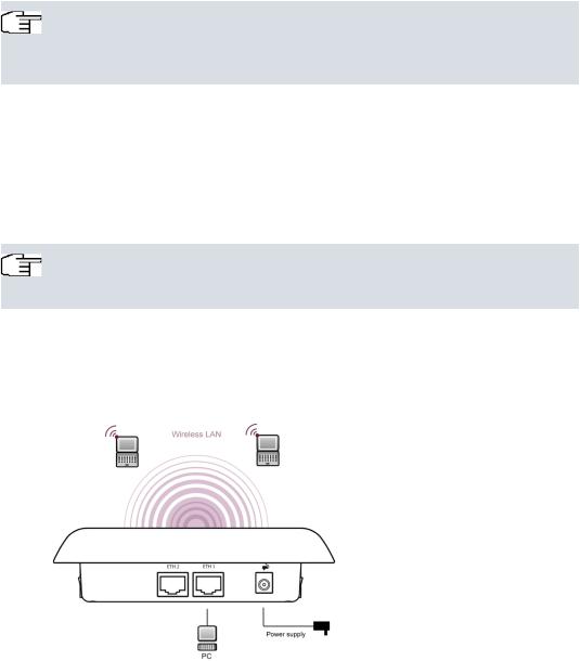
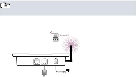
The devices bintec W1001n, bintec W1003n, bintec W2003n and bintec W2004n are equipped integrated antennas. Their radiation is optimized for ceiling mounting.
The device bintec W2003n-ext uses external antennas.
Fig. 1: Connection options bintec W2003n , bintec W2003n-ext, bintec W2004n
bintec Next Generation WLAN |
1 |
|
|
1 Installation |
bintec elmeg GmbH |
|
|
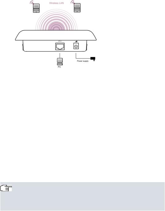
Fig. 2: Connection options bintec W1001n and bintec W1003n
When setting up and connecting, carry out the steps in the following sequence:
(1)Antennas
For bintec W2003n-ext screw the standard antennas (accessory) on to the connectors provided for this purpose. If you are using alternative antennas, please note that you have to connect MIMO antennas to the ports Ant 1 and Ant 2 and a SIMO antenna to port Ant1.
(2)LAN
For the standard configuration of your device via Ethernet, connect port ETH1 or ETH2 of your device to your LAN using the Ethernet cable supplied. bintec W1001n and bintec W1003n has a single Gigabit Ethernet port, ETH1.
The device automatically detects whether it is connected to a switch or directly to a PC.
Use just one of the ports ETH1 and ETH2, the second port is used to cascade a number of devices. If you use both Ethernet connections on the same switch, loops may be formed.
The standard patch cable (RJ45-RJ45) is symmetrical. It is therefore not possible to mix up the cable ends.
(3)Power connection
Note
The devices bintec W1001n, bintec W1003n, bintec W2003n, bintec W2003n-ext and bintec W2004n are supplied without a mains unit. The power adapter with EU plug (part number 5500001254) is available as an accessory.
Connect the device to a mains socket. Use the power cord and insert it in the appropriate socket on your device. Now plug the power cord into a power socket
2 |
bintec Next Generation WLAN |
|
|

bintec elmeg GmbH |
1 Installation |
|
|
(100–240 V). The status LED signal that your device is correctly connected to the power supply. Optionally, power can be supplied through a standard PoE injector (part number 5530000082).
Installation
The access points are to be mounted either on the wall or on the ceiling, or use as a tabletop device.
Use as a table-top device
Attach the four self-adhesive feet on the bottom of the device. Place your device on a solid, level base.
Wall-/ Ceilingmounting
To attach the devices bintec W1001n, bintec W1003n, bintec W2003n, bintec W2003n-ext or bintec W2004n to the wall or ceiling, use the appropriate support is included (part number 5500001278).
Warning
Before drilling, make sure that there are no building installations where you are drilling. If gas, electricity, water or waste water lines are damaged, you may endanger your life or damage property.
•Screw the mount to the wall or ceiling.
•Hang the device in the mount with the screw nut but do not tighten it. Make sure the device connections are accessible.
•If desired, protect the device against theft with a Kensington lock.
bintec Next Generation WLAN |
3 |
|
|
1 Installation |
bintec elmeg GmbH |
|
|
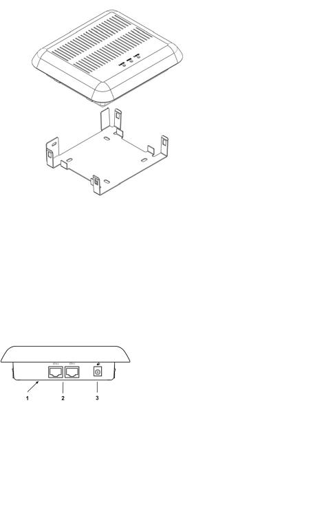
Fig. 3: Ceilingmounting
1.1.2 Connectors
All the connections are located on the underside of the device.
bintec W1001n and bintec W1003n has an Ethernet port, bintec W2003n, bintec W2003n-ext and bintec W2004n have two Ethernet ports.
The connections are arranged as follows:
Fig. 4: Underside bintec W2003n, bintec W2003n-ext and bintec W2004n
Underside of bintec W2003n, bintec W2003n-ext and bintec W2004n
1 |
RESET |
Reset button performs restart (base plate of the device) |
|
|
|
2 |
ETH1/PoE und |
|
|
ETH2 |
10/100/1000 Base-T Ethernet interfaces. |
|
|
|
|
|
In bintec W1001n and bintec W1003n only ETH1 is avail- |
|
|
able! |
|
|
|
4 |
bintec Next Generation WLAN |
|
|
bintec elmeg GmbH |
|
1 Installation |
||
|
|
|
|
|
|
|
|
|
|
3 |
POWER |
Socket for power supply |
||
|
|
|
|
|
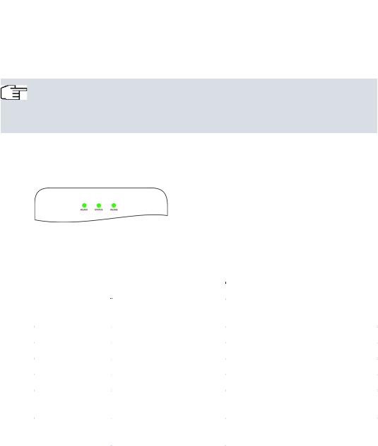
1.1.3 LEDs
The LEDs show the radio status and radio activity of your device.
Note
Note that the number of active WLAN LEDs depends on the number of existing wireless modules.
The LEDs on bintec W1003n, bintec W2003n, bintec W2003n-ext and bintec W2004n are arranged as follows:
Fig. 5: LEDs of bintec W1003n, bintec W2003n, bintec W2003n-ext and bintec W2004n
In operation mode, the LEDs display the following status information for your device:
LED status display
LED |
Status |
Information |
|
|
|
Status (green) |
off |
The power supply is not connected. If |
|
|
other LEDs are on, also Error. |
|
on (static) |
Error |
|
on (flashing) |
Ready |
WLAN 1/2 (green) |
off |
Radio or all assigned VSS inactive |
|
on (slowly flashing) |
VSS is active, no client connected |
|
on (fast flashing) |
VSS is active, at least one client con- |
|
|
nected |
|
on (flickering) |
VSS is active, at least one client con- |
|
|
nected, active data traffic |
|
|
|
The LEDs on bintec W1001n are arranged as follows:
bintec Next Generation WLAN |
5 |
|
|

1 Installation |
bintec elmeg GmbH |
|
|
Fig. 6: LEDs of bintec W1001n
In operation mode, the LEDs display the following status information for your device:
LED status display
LED |
Status |
Information |
|
|
|
LAN |
|
No function |
PWR (green) |
off |
The power supply is not connected. If |
|
|
other LEDs are on, also Error. |
|
on (static) |
Error |
|
on (flashing) |
Ready |
W (green) |
off |
Radio or all assigned VSS inactive |
|
on (slowly flashing) |
VSS is active, no client connected |
|
on (fast flashing) |
VSS is active, at least one client con- |
|
|
nected |
|
|
|
You can choose from three different operation modes of the LEDs in the Global Settings menu as well as with the WLAN Controller.
Note
If you change the LED behavior through the GUI or the WLAN Controller, this setting is preserved if you reset the device to the ex-works state.
State |
All LEDs show their standard behavior. |
Flashing |
Only the status LED flashes once per second. |
Off |
All LEDs are deactivated. |
|
|
1.1.4 Scope of supply
Your device comes with the following accessories:
Cable sets/mains unit/other |
Documentation |
bintec W1001n |
|
Ethernet cable (RJ-45, STP) |
Quick Install Guide (printed) |
Self-adhesive feet |
R&TTE Compliance Information |
6 |
bintec Next Generation WLAN |
|
|
bintec elmeg GmbH |
1 Installation |
|
|
|
Cable sets/mains unit/other |
Documentation |
|
|
|
|
Wall or ceiling mounting |
(printed) |
|
|
User's Guide (on DVD) |
|
|
Safety notices |
|
|
|
bintec W1003n |
Ethernet cable (RJ-45, STP) |
Quick Install Guide (printed) |
|
||
|
Self-adhesive feet |
R&TTE Compliance Information |
|
|
(printed) |
|
Wall or ceiling mounting |
|
|
|
User's Guide (on DVD) |
|
|
Safety notices |
|
|
|
bintec W2003n |
Ethernet cable (RJ-45, STP) |
Quick Install Guide (printed) |
|
||
|
Self-adhesive feet |
R&TTE Compliance Information |
|
|
(printed) |
|
Wall or ceiling mounting |
|
|
|
User's Guide (on DVD) |
|
|
Safety notices |
|
|
|
bintec W2003n-ext |
Ethernet cable (RJ-45, STP) |
Quick Install Guide (printed) |
|
||
|
4 external standard RSMA antennas |
R&TTE Compliance Information |
|
|
(printed) |
|
Self-adhesive feet |
|
|
|
User's Guide (on DVD) |
|
Wall or ceiling mounting |
|
|
|
Safety notices |
|
|
|
bintec W2004n |
Ethernet cable (RJ-45, STP) |
Quick Install Guide (printed) |
|
||
|
Self-adhesive feet |
R&TTE Compliance Information |
|
|
(printed) |
|
Wall or ceiling mounting |
|
|
|
User's Guide (on DVD) |
|
|
Safety notices |
|
|
|
1.1.5 General Product Features
The general product features cover performance features and the technical prerequisites for installation and operation of your device.
The features are summarised in the following table:
General Product Features
bintec Next Generation WLAN |
7 |
|
|

1 Installation |
bintec elmeg GmbH |
||
|
|
|
|
|
|
|
|
|
Property |
Value |
|
|
|
|
|
|
Dimensions and weights: |
|
|
|
|
|
|
|
|
ca. 162 x 145 x 45 mm |
|
|
Equipment dimensions without cable |
|
|
|
(W x L x H) |
|
|
|
|
|
|
|
Weight |
approx. 1,000 g (with WLAN modules) |
|
|
|
|
|
|
LEDs |
bintec W1001n: 3 (1x LAN, 1x Power, 1x WLAN) |
|
|
|
||
|
|
bintec W1003n: 3 (1x Power, 1x WLAN, 1x Ethernet) |
|
|
|
bintec W2003n, bintec W2003n-ext and bintec |
|
|
|
W2004n: 4 (1x Power, 2x WLAN, 2x Ethernet) |
|
|
|
|
|
|
Power consumption of the device |
max. 12 W |
|
|
|
|
|
|
Voltage supply |
9 V, 1.3 A (The power adapter with the part number |
|
|
|
5500001254 is available as an accessory.) |
|
|
|
PoE an Ethernet 1 Class 0, according to 802.3af (max. |
|
|
|
12.4 W). The Gigabit PoE Injector with part number |
|
|
|
5530000082 is available as an accessory. |
|
|
|
|
|
|
Environmental requirements: |
|
|
|
|
|
|
|
Storage temperature |
-40 °C to +85 °C |
|
|
|
|
|
|
Operating temperature |
0 °C to +40 °C |
|
|
|
|
|
|
Relative atmospheric humidity |
10 % to 100 % |
|
|
|
|
|
|
Available interfaces: |
|
|
|
|
|
|
|
WLAN |
bintec W1001n, bintec W1003n: 1 Radio module |
|
|
|
||
|
|
802.11abgn 2,4 oder 5GHz Mimo 2x2 |
|
|
|
bintec W2003n: 1 Radio module 802.11bgn 2,4GHz |
|
|
|
Mimo 2x2; 1 Radiomodul 802.11an 5GHz Mimo 2x2 |
|
|
|
bintec W2003n-ext: 1 Radio module 802.11abgn 2,4 |
|
|
|
or 5GHz Mimo 2x2; 1 Radio module 802.11abgn 2,4 or |
|
|
|
5GHz Mimo 2x2 |
|
|
|
bintec W2004n: 1 Radio module 802.11bgn 2,4GHz |
|
|
|
Mimo 3x3; 1 Radiomodul 802.11an 5GHz Mimo 3x3 |
|
|
|
|
|
|
Ethernet IEEE 802.3 LAN |
10/100/1000 mbps |
|
|
|
|
|
|
Available sockets: |
|
|
|
|
|
|
|
Ethernet interface |
bintec W1001n, bintec W1003n: 1 RJ45 socket |
|
|
|
||
|
|
bintec W2003n, bintec W2003n-ext and bintec |
|
|
|
W2004n: 2 RJ45 sockets |
|
|
|
|
|
|
Antennas: |
|
|
|
|
|
|
8 |
bintec Next Generation WLAN |
|
|

bintec elmeg GmbH |
1 Installation |
||
|
|
|
|
|
|
|
|
|
Property |
Value |
|
|
|
|
|
|
Antenna connection |
bintec W1001n, bintec W1003n: 2 internal antennas |
|
|
|
||
|
|
bintec W2003n: 4 internal antennas |
|
|
|
bintec W2003n-ext: 4 externe dualband antennas |
|
|
|
bintec W2004n: 6 internal antennas |
|
|
|
|
|
|
Transmit Power (WLAN) |
max. 100 mW (20 dBm) EIRP |
|
|
|
|
|
|
Standards & Guidelines |
R&TTE Directive 1999/5/EC |
|
|
|
EN 60950-1 (IEC60950); EN 60950-22; EN 301489-1; |
|
|
|
EN301489-17; EN 55022; EN 300328-1; EN 301893; EN |
|
|
|
302502; EN 50371 |
|
|
|
|
|
|
Buttons |
Reset |
|
|
|
|
|
1.1.6 Reset
If the configuration is incorrect or if your device cannot be accessed, you can reset the device to the ex works standard settings using the Reset button on the bottom of the device.
All existing configuration data will be deleted.
(1)Press the Reset button on your device.
(2)Keep the Reset button on your device pressed.
(3)Look at the LEDs:
The Staus LED is lit. the device runs through the boot sequence.
When the Status LED starts flashing again, release the Reset button.
You can now configure your device again as described from Basic configuration on page 25
.
Note
If you delete the boot configuration using the GUI, all passwords will also be reset and the current boot configuration deleted. The next time, the device will boot with the standard ex works settings.
Note
If you have changed the LED behavior to something other then the default value, this setting is preserved after resetting the device.
bintec Next Generation WLAN |
9 |
|
|
1 Installation |
bintec elmeg GmbH |
|
|
1.2 bintec WI1003n
1.2.1 Setting up and connecting
Note
All you need for this are the cables supplied with the equipment.
The device bintec WI1003n uses external antennas.
Fig. 7: Connection options bintec WI1003n
When setting up and connecting, carry out the steps in the following sequence:
(1)Antennas
Screw the standard antennas (accessory) on to the connectors provided for this purpose. If you are using alternative antennas, please note that you have to connect MIMO antennas to the ports Ant 1-1 and Ant 2-2.
(2)LAN
For the standard configuration of your device via Ethernet, connect port ETH1 or ETH2 of your device to your LAN using the Ethernet cable supplied.
The device automatically detects whether it is connected to a switch or directly to a PC.
Use just one of the ports ETH1 and ETH2, the second port is used to cascade a number of devices. If you use both Ethernet connections on the same switch, loops may be formed.
The standard patch cable (RJ45-RJ45) is symmetrical. It is therefore not possible to mix up the cable ends.
(3)Power connection
10 |
bintec Next Generation WLAN |
|
|
bintec elmeg GmbH |
1 Installation |
|
|
Note
The devices are supplied without a mains unit. The power adapter with EU plug (part number 5500001254) is available as an accessory.
Connect the device to a mains socket. Use the power cord and insert it in the appropriate socket on your device. Now plug the power cord into a power socket (100–240 V). The status LED signal that your device is correctly connected to the power supply. Optionally, power can be supplied through a standard PoE injector (part number 5530000082).
Installation
The access points are to be mounted either on the wall or on the ceiling, or use as a tabletop device.
With the DIN rail adapter-supplied, the access points can be mounted in a control panel.
Use as a table-top device
Attach the four self-adhesive feet on the bottom of the device. Place your device on a solid, level base.
Wall-/ Ceilingmounting
To attach the devices bintec WI1003n to the wall or ceiling, use the appropriate support is included (part number 5500001278).
Control Panel
For installation in a control panel, use the DIN DIN rail adapter is included.
Warning
Before drilling, make sure that there are no building installations where you are drilling. If gas, electricity, water or waste water lines are damaged, you may endanger your life or damage property.
•Screw the mount to the wall or ceiling.
•Hang the device in the mount with the screw nut but do not tighten it. Make sure the device connections are accessible.
•If desired, protect the device against theft with a Kensington lock.
bintec Next Generation WLAN |
11 |
|
|

1 Installation |
bintec elmeg GmbH |
|
|
1.2.2 Connectors
All the connections are located on the underside of the device. bintec WI1003n have two
Ethernet ports.
The connections are arranged as follows:
Fig. 8: Connectors bintec WI1003n
Connectors bintec WI1003n
1 |
RESET |
Reset button performs restart (base plate of the device) |
2ETH1/PoE und
|
ETH2 |
10/100/1000 Base-T Ethernet interfaces. |
|
|
|
|
|
|
3 |
POWER |
Socket for power supply |
1.2.3 LEDs
The LEDs show the radio status and radio activity of your device.
Note
Note that the number of active WLAN LEDs depends on the number of existing wireless modules.
The LEDs on bintec WI1003n are arranged as follows:
Fig. 9: LEDs of bintec WI1003n
In operation mode, the LEDs display the following status information for your device:
LED status display
LED |
Status |
Information |
|
|
|
Status (green) |
off |
The power supply is not connected. If |
|
|
other LEDs are on, also Error. |
|
|
|
12 |
bintec Next Generation WLAN |
|
|

bintec elmeg GmbH |
|
1 Installation |
||
|
|
|
|
|
|
|
|
|
|
|
LED |
Status |
Information |
|
|
|
|
|
|
|
|
on (static) |
Error |
|
|
|
on (flashing) |
Ready |
|
|
WLAN 1/2 (green) |
off |
Radio or all assigned VSS inactive |
|
|
|
on (slowly flashing) |
VSS is active, no client connected |
|
|
|
on (fast flashing) |
VSS is active, at least one client con- |
|
|
|
|
nected |
|
|
|
on (flickering) |
VSS is active, at least one client con- |
|
|
|
|
nected, active data traffic |
|
|
|
|
|
|
You can choose from three different operation modes of the LEDs in the Global Settings menu as well as with the WLAN Controller.
Note
If you change the LED behavior through the GUI or the WLAN Controller, this setting is preserved if you reset the device to the ex-works state.
State |
All LEDs show their standard behavior. |
Flashing |
Only the status LED flashes once per second. |
Off |
All LEDs are deactivated. |
|
|
1.2.4 Scope of supply
Your device comes with the following accessories:
Cable sets/mains unit/other |
Documentation |
bintec WI1003n |
|
Ethernet cable (RJ-45, STP) |
Quick Install Guide (printed) |
Self-adhesive feet |
R&TTE Compliance Information |
|
(printed) |
Wall or ceiling mounting |
|
|
User's Guide (on DVD) |
|
Safety notices |
1.2.5 General Product Features
The general product features cover performance features and the technical prerequisites for installation and operation of your device.
bintec Next Generation WLAN |
13 |
|
|

1 Installation |
bintec elmeg GmbH |
|
|
The features are summarised in the following table:
General Product Features
Property |
Value |
|
|
Dimensions and weights: |
|
|
|
|
ca. 149 x 123 x 31 mm |
Equipment dimensions without cable |
|
(W x L x H) |
|
|
|
Weight |
approx. 750 g (with WLAN modules) |
|
|
LEDs |
1x Power, 2x WLAN |
|
|
Power consumption of the device |
max. 12 W |
|
|
Voltage supply |
9 V, 1.3 A (The power adapter with the part number |
|
5500001254 is available as an accessory.) |
|
PoE an Ethernet 1 Class 0, according to 802.3af (max. |
|
12.4 W). The Gigabit PoE Injector with part number |
|
5530000082 is available as an accessory. |
|
|
Environmental requirements: |
|
|
|
Storage temperature |
-40 °C to +85 °C |
|
|
Operating temperature |
-20 °C to +45 °C |
|
|
Relative atmospheric humidity |
10 % to 100 % |
|
|
Available interfaces: |
|
|
|
WLAN |
1 Radio module 802.11abgn 2,4 or 5 GHz Mimo 2x2 |
|
|
Ethernet IEEE 802.3 LAN |
10/100/1000 mbps |
|
|
Available sockets: |
|
|
|
Ethernet interface |
2 RJ45 sockets |
|
|
Antennas: |
|
|
|
Antenna connection |
2 externe dualband antennas |
|
|
Standards & Guidelines |
R&TTE Directive 1999/5/EC |
|
EN 60950-1 (IEC60950); EN 60950-22; EN 301489-1; |
|
EN301489-17; EN 55022; EN 300328-1; EN 301893; EN |
|
302502; EN 50371 |
|
|
Buttons |
Reset |
|
|
14 |
bintec Next Generation WLAN |
|
|

bintec elmeg GmbH |
1 Installation |
|
|
1.2.6 Reset
If the configuration is incorrect or if your device cannot be accessed, you can reset the device to the ex works standard settings using the Reset button on the bottom of the device.
All existing configuration data will be deleted.
(1)Press the Reset button on your device.
(2)Keep the Reset button on your device pressed.
(3)Look at the LEDs:
The Staus LED is lit. the device runs through the boot sequence.
When the Status LED starts flashing again, release the Reset button.
You can now configure your device again as described from Basic configuration on page 25
.
Note
If you delete the boot configuration using the GUI, all passwords will also be reset and the current boot configuration deleted. The next time, the device will boot with the standard ex works settings.
Note
If you have changed the LED behavior to something other then the default value, this setting is preserved after resetting the device.
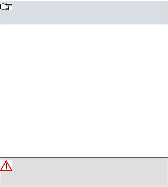
1.3 bintec WO1003n and bintec WO2003n
1.3.1 Setting up and connecting
The devices bintec WO1003n and bintec WO2003n use external antennas.
bintec Next Generation WLAN |
15 |
|
|
1 Installation |
bintec elmeg GmbH |
|
|
Fig. 10: Connectors of bintec WO2003n
When setting up and connecting, carry out the steps in the following sequence:
(1)Antennas
Screw standard antennas (accessory) on to the connectors provided for this purpose.
Radio module 1 is assigned to connectors 1-1 / 1-2; radio module 2 to connectors 2-1 / 2-2. If you connect standard antenna (MIMO) to only a single antenna connector, remember to disable the second stream in the radio configuration. If you use different antennas, make sure to connect them to the connectores of the proper radio modules.
(2)LAN
For the standard configuration of your device via Ethernet, connect port ETH1 or ETH2 of your device to your LAN using an Ethernet cable tailored with the RJ industrial connector supplied.
Note
Note that while it is possible to insert a standard RJ45 plug into the LAN port of the device, it will be difficult to remove it again. We recommend using the supplied connector kit.
The device automatically detects whether it is connected to a switch or directly to a
PC.
16 |
bintec Next Generation WLAN |
|
|
Loading...