


bintec elmeg GmbH |
Manual |
|
|
Manual bintec Next Generation WLAN
Copyright© Version 1.12 (SVN 8349) 01/2019 bintec elmeg GmbH
bintec Next Generation WLAN |
1 |
|
|
Manual |
bintec elmeg GmbH |
|
|
Legal Notice
Warranty
This publication is subject to change.
bintec elmeg GmbH offers no warranty whatsoever for information contained in this manual. bintec elmeg GmbH is not liable for any direct, indirect, collateral, consequential or any other damage connected to the delivery, supply or use of this manual.
Copyright © bintec elmeg GmbH.
All rights to the data included, in particular the right to copy and propagate, are reserved by bintec elmeg GmbH.
2 |
bintec Next Generation WLAN |
|
|
bintec elmeg GmbH |
Table of Contents |
|
|
Table of Contents
Chapter 1 Installation. . . . . . . . . . . . . . . . . . . . . . . . . . . . 1
1.1bintec W2022ac and bintec W2022ac-ext . . . . . . . . . . . . . . . 1
1.1.1Setting up and connecting . . . . . . . . . . . . . . . . . . . . . . 1
1.1.2 |
Connectors . . . . . . . . . . . . . . . . . . . . . . . . . . . . 3 |
1.1.3LEDs . . . . . . . . . . . . . . . . . . . . . . . . . . . . . . . 3
1.1.4 |
Scope of supply . . . . . . . . . . . . . . . . . . . . . . . . . . 5 |
1.1.5General Product Features . . . . . . . . . . . . . . . . . . . . . . 5
1.1.6 |
Reset . . . . . . . . . . . . . . . . . . . . . . . . . . . . . . . |
6 |
1.2 |
Cleaning . . . . . . . . . . . . . . . . . . . . . . . . . . . . . |
7 |
1.3Pin Assignments . . . . . . . . . . . . . . . . . . . . . . . . . . 7
1.3.1 |
Ethernet interface. . . . . . . . . . . . . . . . . . . . . . . . . . |
7 |
1.4 |
Frequencies and channels . . . . . . . . . . . . . . . . . . . . . . |
8 |
1.5Support information . . . . . . . . . . . . . . . . . . . . . . . . . 8
Chapter 2 |
Basic configuration . . . . . . . . . . . . . . . . . . . . . . . |
9 |
2.1 |
Presettings . . . . . . . . . . . . . . . . . . . . . . . . . . . . |
9 |
2.1.1Preconfigured data . . . . . . . . . . . . . . . . . . . . . . . . . 9
2.1.2 |
Software update . . . . . . . . . . . . . . . . . . . . . . . . . |
10 |
2.2 |
System requirements . . . . . . . . . . . . . . . . . . . . . . . |
10 |
2.3 |
Preparation . . . . . . . . . . . . . . . . . . . . . . . . . . . |
10 |
2.3.1Gathering data . . . . . . . . . . . . . . . . . . . . . . . . . . 11
2.3.2 |
Configuring a PC . . . . . . . . . . . . . . . . . . . . . . . . . |
12 |
2.4 |
IP configuration. . . . . . . . . . . . . . . . . . . . . . . . . . |
13 |
2.5 |
Modify system password. . . . . . . . . . . . . . . . . . . . . . |
14 |
2.6 |
Software Update . . . . . . . . . . . . . . . . . . . . . . . . . |
15 |
bintec Next Generation WLAN |
i |
|
|
Table of Contents |
bintec elmeg GmbH |
|
|
Chapter 3 |
System Management . . . . . . . . . . . . . . . . . . . . |
16 |
3.1 |
Status . . . . . . . . . . . . . . . . . . . . . . . . . . . . . |
16 |
3.2 |
Global Settings . . . . . . . . . . . . . . . . . . . . . . . . . |
17 |
3.2.1System . . . . . . . . . . . . . . . . . . . . . . . . . . . . . 17
3.2.2 |
Passwords . . . . . . . . . . . . . . . . . . . . . . . . . . . |
19 |
3.2.3 |
Date and Time . . . . . . . . . . . . . . . . . . . . . . . . . . |
20 |
3.3 |
Remote Authentication . . . . . . . . . . . . . . . . . . . . . . |
23 |
3.3.1 |
RADIUS . . . . . . . . . . . . . . . . . . . . . . . . . . . . |
23 |
Chapter 4 LAN . . . . . . . . . . . . . . . . . . . . . . . . . . . . . . 26
4.1VLAN/Bridge Groups . . . . . . . . . . . . . . . . . . . . . . . 26
4.1.1 |
Port Configuration . . . . . . . . . . . . . . . . . . . . . . . . |
26 |
4.2 |
IP Configuration . . . . . . . . . . . . . . . . . . . . . . . . . |
27 |
4.2.1Interfaces . . . . . . . . . . . . . . . . . . . . . . . . . . . . 27
Chapter 5 |
Wireless LAN . . . . . . . . . . . . . . . . . . . . . . . . . |
30 |
5.1 |
WLAN . . . . . . . . . . . . . . . . . . . . . . . . . . . . . |
30 |
5.1.1 |
Radio Settings . . . . . . . . . . . . . . . . . . . . . . . . . . |
30 |
5.1.2 |
Wireless Networks (VSS) . . . . . . . . . . . . . . . . . . . . . |
35 |
Chapter 6 |
Maintenance . . . . . . . . . . . . . . . . . . . . . . . . . |
42 |
6.1 |
Software & Configuration . . . . . . . . . . . . . . . . . . . . . |
42 |
6.1.1 |
Options . . . . . . . . . . . . . . . . . . . . . . . . . . . . . |
42 |
6.2Reboot . . . . . . . . . . . . . . . . . . . . . . . . . . . . . 45
6.2.1 |
System Reboot . . . . . . . . . . . . . . . . . . . . . . . . . |
45 |
6.3 |
Factory Reset . . . . . . . . . . . . . . . . . . . . . . . . . . |
45 |
ii |
bintec Next Generation WLAN |
|
|
bintec elmeg GmbH |
Table of Contents |
|
|
Chapter 7 |
External Reporting . . . . . . . . . . . . . . . . . . . . . . |
47 |
7.1 |
SIA . . . . . . . . . . . . . . . . . . . . . . . . . . . . . . . |
47 |
7.1.1SIA . . . . . . . . . . . . . . . . . . . . . . . . . . . . . . . 47
Chapter 8 |
Monitoring . . . . . . . . . . . . . . . . . . . . . . . . . . |
48 |
8.1 |
Internal Log . . . . . . . . . . . . . . . . . . . . . . . . . . . |
48 |
8.1.1 |
System Messages . . . . . . . . . . . . . . . . . . . . . . . . |
48 |
8.2Interfaces . . . . . . . . . . . . . . . . . . . . . . . . . . . . 48
8.2.1 |
Statistics . . . . . . . . . . . . . . . . . . . . . . . . . . . . |
48 |
8.2.2 |
Network Status . . . . . . . . . . . . . . . . . . . . . . . . . |
50 |
8.3 |
WLAN . . . . . . . . . . . . . . . . . . . . . . . . . . . . . |
50 |
8.3.1 |
VSS . . . . . . . . . . . . . . . . . . . . . . . . . . . . . . |
50 |
8.3.2 |
Neighbor APs . . . . . . . . . . . . . . . . . . . . . . . . . . |
51 |
Index . . . . . . . . . . . . . . . . . . . . . . . . . . . . . 52
bintec Next Generation WLAN |
iii |
|
|
Table of Contents |
bintec elmeg GmbH |
|
|
iv |
bintec Next Generation WLAN |
|
|

bintec elmeg GmbH |
1 Installation |
|
|
Chapter 1 Installation
Note
Please read the safety notices carefully before installing and starting up your device.
These are supplied with the device.
1.1 bintec W2022ac and bintec W2022ac-ext
1.1.1 Setting up and connecting
Note
All you need for this are the cables supplied with the equipment.
The device bintec W2022ac equipped integrated antennas. Their radiation is optimized for ceiling mounting.
The device bintec W2022ac-ext uses external antennas.
When setting up and connecting, carry out the steps in the following sequence:
(1)Antennas
For bintec W2022ac-ext screw the provided standard antennas on to the connectors provided for this purpose.
(2)LAN
For the standard configuration of your device via Ethernet, connect port LAN1 of your device to your PC .
The device automatically detects whether it is connected to a switch or directly to a PC.
Use just one of the ports LAN1 and LAN2, the second port is used to cascade a number of devices. If you use both Ethernet connections on the same switch, loops may be formed.
The standard patch cable (RJ45-RJ45) is symmetrical. It is therefore not possible to mix up the cable ends.
(3)Power connection
bintec Next Generation WLAN |
1 |
|
|
1 Installation |
bintec elmeg GmbH |
|
|
Note
The devices are supplied without a mains unit. The power adapter with EU plug (part number 5500002091) is available as an accessory.
Connect the device to a mains socket. Use the power cord and insert it in the appropriate socket on your device. Now plug the power cord into a power socket (100–240 V). The status LED signal that your device is correctly connected to the power supply. Optionally, power can be supplied through a standard PoE injector (part number 5530000338).
Installation
The access points are to be mounted either on the wall or on the ceiling, or use as a tabletop device.
Use as a table-top device
The device have integrated rubber pads. Place your device on a solid, level base.
Wall-/ Ceilingmounting
The devices are to be mounted by tabs on the back of the housing to the wall. A ceiling mount is available as an accessory to mount the device on the ceiling (article number 5520000163). The ceiling mount allows mounting on suspended system ceilings without drilling and dowels.
Warning
Before drilling, make sure that there are no building installations where you are drilling. If gas, electricity, water or waste water lines are damaged, you may endanger your life or damage property.
•Use the bracket as a template to mark out the drilling holes.
•Screw the bracket to the wall or ceiling with the provided dowels and screws.
•When mounting the unit to the struts of an intermediate ceiling, screw the supplied plastic clips to the back of the bracket.
•Connect all necessary cables (Ethernet, power supply) to the access point before inserting it into the bracket.
Make sure that the cables are not a source of danger! Guide the cables through the cable guides!
•Fit the device onto the 3 metal pins and push it down until it clicks into place. When
2 |
bintec Next Generation WLAN |
|
|
bintec elmeg GmbH |
1 Installation |
|
|
mounting to an intermediate ceiling, push the plastic clips against the braces so that they click into place, too.
• If necessary, secure the device with a Kensington® lock against theft.
Ceilingmounting
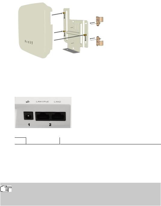
1.1.2 Connectors
The connections are located on the underside of the device:
Underside
1 |
POWER |
Socket for power supply |
2LAN1/PoE und
LAN2 |
10/100/1000 Base-T Ethernet interfaces. |
|
1.1.3 LEDs
The LEDs show radio status and radio activity of your device.
Note
Note that the number of active WLAN LEDs depends on the number of existing wireless modules.
bintec Next Generation WLAN |
3 |
|
|

1 Installation |
bintec elmeg GmbH |
|
|
The LEDs are arranged as follows:
In operation mode, the LEDs display the following status information for your device:
LED status display
LED |
Colour |
Status |
Information |
|
|
|
|
Status |
green |
off |
No power supply connected. Error if other |
|
|
|
LEDs are lit. |
|
green |
on (flashing) |
Normal operation |
|
red |
on (static) |
Failure |
|
red |
on (flashing |
Management communication error |
LAN 1/2 |
|
off |
No LAN |
|
yellow |
on (static) |
10 Mbit/s or 100 Mbit/s active |
|
yellow |
on (flashing) |
10 Mbit/s or 100 Mbit/s data traffic |
|
green |
on (static) |
1000 Mbit/s active |
|
green |
on (flashing) |
1000 Mbit/s data traffic |
WLAN 1/2 |
|
off |
Radio module and/or SSIDs inactive |
|
|
on |
Failure |
|
|
on (slowly |
SSID active, no client is authenticated |
|
|
blinking) |
|
|
|
on (fast blink- |
SSID active, one or more clients authenticated |
|
|
ing) |
|
|
|
on (flashing) |
SSiD active, one or more clients authenticated |
|
|
|
and data traffic |
|
|
|
|
You can choose from three different operation modes of the LEDs in the System Manage- ment->Global Settings->System menu.
Note
If you change the LED behavior through the GUI, this setting is preserved if you reset the device to the ex-works state.
Normal |
All LEDs show their standard behavior. |
|
|
4 |
bintec Next Generation WLAN |
|
|
bintec elmeg GmbH |
1 Installation |
|
|
Minimal |
Only the status LED flashes once per second. |
Off |
All LEDs are deactivated. |
|
|
1.1.4 Scope of supply
Your device comes with the following accessories:
|
Cable sets/mains unit/other |
Documentation |
|
|
|
bintec W2022ac |
bintec W2022ac |
Installation poster |
|
|
Safety notices |
|
|
|
bintec W2022ac-ext |
bintec W2022ac-ext |
Installation poster |
|
4 external standard WLAN antennas |
Safety notices |
|
|
|
1.1.5 General Product Features
The general product features cover performance features and the technical prerequisites for installation and operation of your device.
The features are summarised in the following table:
General Product Features
Property |
Value |
|
|
Dimensions and weights: |
|
|
|
Equipment dimensions without cable |
ca. 190 x 190 x 38 mm |
(W x D x H) |
|
|
|
Weight |
approx. 505 g |
|
|
LEDs |
4 (1x Power, 2x WLAN, 2x Ethernet) |
|
|
Power consumption of the device |
max. 8.95 W |
|
|
Voltage supply |
12 V, 1.5 A (The power adapter with the part number |
|
5500002091 is available as an accessory.) |
|
PoE an Ethernet 1 Class 0, according to 802.3af (max. |
|
12.4 W). The Gigabit PoE Injector with part number |
|
5530000082 is available as an accessory. |
|
|
Environmental requirements: |
|
|
|
Storage temperature |
-10 °C to +70 °C |
|
|
Operating temperature |
0 °C to +40 °C |
|
|
Relative atmospheric humidity |
10 % to 90 % |
|
|
bintec Next Generation WLAN |
5 |
|
|

1 Installation |
bintec elmeg GmbH |
||
|
|
|
|
|
|
|
|
|
Property |
Value |
|
|
|
|
|
|
Available interfaces: |
|
|
|
|
|
|
|
WLAN |
One radio module IEEE 802.11bgn MIMO 2x2 and a |
|
|
|
second radio module IEEE 802.11ac/an MU-MIMO 2x2 |
|
|
|
allow simultaneous operation at 2.4 and 5 GHz. |
|
|
|
|
|
|
LAN/WAN |
2 x 10/100/1000 mbps |
|
|
|
|
|
|
PoE (Power-over-Ethernet) |
Power-over-Ethernet according IEEE 802.3af, compatible |
|
|
|
with 802.3at PoE injectors |
|
|
|
|
|
|
Available sockets: |
|
|
|
|
|
|
|
Ethernet interface |
2 RJ45 sockets |
|
|
|
|
|
|
Antennas: |
|
|
|
|
|
|
|
Antenna connection |
bintec W2022ac: Integrated single band MIMO an- |
|
|
|
tenna array with two antenna elements for each radio; 2 |
|
|
|
dBm gain @ 2,4 GHz; 3 dBm gain @ 5 GHz. |
|
|
|
bintec W2022ac-ext: Two external antennas with |
|
|
|
omni characteristic for each radio module, RSMA socket, |
|
|
|
appr. 1,5 dBm |
|
|
|
|
|
|
Transmit Power (WLAN) |
max. 100 mW (20 dBm) EIRP |
|
|
|
|
|
|
Standards & Guidelines |
Directive 2014/53/EU, 2011/65/EU, 2009/125/EU, EN |
|
|
|
60950-1; EN 62311; EN 301489-1; EN301489-17; EN |
|
|
|
300 328; EN 301893; EN 50581; EN 60601-1-2 (Medical |
|
|
|
devices - part 1-2) |
|
|
|
|
|
|
Buttons |
Reset button for restart or reset |
|
|
|
|
|
1.1.6 Reset
If the configuration is incorrect or if your device cannot be accessed, you can reset the device to the ex works standard settings using the Reset button on the bottom of the device.
You can reset the access point to the ex works state in either of two ways:
(1)In the menu Maintenance->Factory Reset.
(2)Through the reset button located at the side of the device.
Keep the button pressed until the Status LED flashes at a regular interval again. As a protection against unauthorized use, the reset button may be covered by the mounting bracket. Remove the access point from the bracket in order to access the reset button.
Both methods delete all configurations and passwords.
You can now configure your device again as described from Basic configuration on page 9
6 |
bintec Next Generation WLAN |
|
|
bintec elmeg GmbH |
1 Installation |
|
|
.
Note
If you have changed the LED behavior to something other then the default value, this setting is preserved after resetting the device.
1.2 Cleaning
You can clean your device easily. Use a damp cloth or antistatic cloth. Do not use solvents. Never use a dry cloth; the electrostatic charge could cause electronic faults. Make sure that no moisture can enter the device and cause damage.
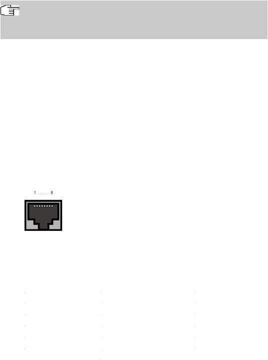
1.3 Pin Assignments
1.3.1 Ethernet interface
The devices bintec W2022ac and bintec W2022ac-ext have two 10/100/1000 Ethernet interfaces.
The connection is made via an RJ45 socket.
The pin assignment for the Ethernet 10/100/1000 Base-T interface (RJ45 socket) is as follows:
RJ45 socet for LAN connection
Pin |
Function |
|
|
|
|
1 |
Pair 0 + |
|
2 |
Pair 0 - |
|
3 |
Pair 1 + |
|
4 |
Pair 2 |
+ |
5 |
Pair 2 |
- |
6 |
Pair 1 |
- |
7 |
Pair 3 |
+ |
|
|
|
bintec Next Generation WLAN |
7 |
|
|

1 Installation |
bintec elmeg GmbH |
|
|
Pin |
Function |
|
|
8 |
Pair 3 - |
|
|
1.4 Frequencies and channels
Different certification regulations apply around the world. ETSI standards generally apply (predominantly used in Europe). For operation in Europe, please read the notes in the RED Compliance Information.
1.5 Support information
If you have any questions about your new product, please contact a local, certified retailer for prompt technical support. Resellers have been trained by us and receive privileged support.
Further information on our support and service offers can be found on our web site at
www.bintec-elmeg.com .
8 |
bintec Next Generation WLAN |
|
|
bintec elmeg GmbH |
2 Basic configuration |
|
|
Chapter 2 Basic configuration
You can use the GUI (other configuration steps) for the basic configuration of your device.
The basic configuration is explained below step-by-step. A detailed online help system gives you extra support.
This user’s guide assumes you have the following basic knowledge:
•Basic knowledge of network structure
•Knowledge of basic network terminology, such as server, client and IP address
•Basic knowledge of using Microsoft Windows operating systems
You can find other useful applications on the Internet at www.bintec-elmeg.com .
2.1 Presettings
2.1.1 Preconfigured data
You have three ways of accessing your device in your network to perform configuration tasks:
(a)Dynamic IP address
In ex works state, your device is set to DHCP client mode, which means that when it is connected to the network, it is automatically assigned an IP address if a DHCP server is run. You can then access your device for configuration purposes using the IP address assigned by the DHCP server. For information on determining the dynamically assigned IP address, please see your DHCP server documentation.
(b)Fallback IP address
If you do not run a DHCP server, you can connect your device directly to your configuration PC and then reach it using the following, predefined fallback IP configuration:
•IP Address:
•Netmask:
Make sure that the PC from which the configuration is performed has a suitable IP configuration (see Configuring a PC on page 12).
(c) Assigning a fixed IP address
Use the following access data to configure your device in an ex works state:
bintec Next Generation WLAN |
9 |
|
|

2 Basic configuration |
bintec elmeg GmbH |
|
|
•User Name:
•Password:
Note
All bintec elmeg devices are delivered with the same username and password. As long as the password remains unchanged, they are therefore not protected against unauthorised use. Make sure you change the passwords to prevent unauthorised access to your device!
How to change the passwords is described in Modify system password on page 14.
2.1.2 Software update
Your device contains the version of the system software available at the time of production. More recent versions may have since been released. You can easily perform an update with the GUI using the Maintenance->Software &Configurationmenu.
For a description of the update procedure, see Software Update on page 15.
2.2 System requirements
For configuration, your PC must meet the following system requirements:
•Suitable operating system (Windows, Linux, MAC OS)
•A web browser (Internet Explorer, Firefox, Chrome) in the current version
•Installed network card (Ethernet)
•TCP/IP protocol installed (see Configuring a PC on page 12)
•High colour display to show the graphics correctly
2.3 Preparation
To prepare for configuration, you need to...
•Obtain the data required for the basic configuration.
•Check whether the PC from which you want to perform the configuration meets the necessary requirements.
10 |
bintec Next Generation WLAN |
|
|

bintec elmeg GmbH |
2 Basic configuration |
|
|
2.3.1 Gathering data
The main data for the basic configuration can be gathered quickly, as no information is required that needs in-depth network knowledge. If applicable, you can use the example values.
Before you start the configuration, you should gather the data for the following purposes:
•IP configuration (obligatory if your device is in the ex works state)
•Configuration of a wireless network connection in Access Point mode
The following table shows examples of possible values for the necessary data. You can enter your personal data in the "Your values" column, so that you can refer to these values later when needed.
If you configure a new network, you can use the given example values for IP addresses and netmasks. In cases of doubt, ask your system administrator.
Basic configuration
For a basic configuration of your gateway, you need information that relates to your network environment:
IP configuration of the access point
Access data |
Example value |
Your values |
|
|
|
IP address of your access point |
|
|
Netmask of your access point |
|
|
|
|
|
Access Point mode
If you run your device in Access Point mode, you can set up the required wireless networks. To do this, you need the following data:
Configuration of a wireless network
Access data |
Example value |
Your values |
|
|
|
Network Name (SSID) |
|
|
Security mode |
|
|
Preshared key |
|
|
|
|
|
bintec Next Generation WLAN |
11 |
|
|
2 Basic configuration |
bintec elmeg GmbH |
|
|
2.3.2 Configuring a PC
In order to reach your device via the network and to be able to carry out configuration, the
PC used for the configuration has to satisfy some prerequisites.
•Make sure that the TCP/IP protocol is installed on the PC.
•Select the suitable IP configuration for your configuration PC.
The PC via which you want to configure the IP address for your device must be in the same network as your device.
Checking the Windows TCP/IP protocol
Proceed as follows to check whether you have installed the protocol:
(1)Click the Windows Start button and then Settings -> Control Panel -> Network Connections (Windows XP) or Control Panel -> Network and Sharing Center-> Change Adapter Settings (from Windows 7 on).
(2)Click on LAN Connection.
(3)Click on Properties in the status window.
(4)Look for the Internet Protocol (TCP/IP) entry in the list of network components.
Installing the Windows TCP/IP protocol
If you cannot find the Internet Protocol (TCP/IP) entry, install the TCP/IP protocol as follows:
(1)First click Properties, then Install in the status window of the LAN Connection.
(2)Select the Protocol entry.
(3)Click Add.
(4)Select Internet Protocol (TCP/IP) and click on OK.
(5)Follow the on-screen instructions and restart your PC when you have finished.
Allocating PC IP address
Allocate an IP address to your PC as follows:
(1)Select Internet Protocol (TCP/IP) and click Properties.
(2)Choose Use following IP address and enter a suitable IP address, the matching netmask, your default gateway and your preferred DNS server.
If you run a DHCP server in your network, you can apply the default Windows setting Obtain IP address automatically and Obtain DNS server address automatically.
12 |
bintec Next Generation WLAN |
|
|
 Loading...