

Page 1
AC
AUTOMAZIONI A PISTONE PER CANCELLI A BATTENTE
PISTON AUTOMATIONS FOR SWING GATES
AUTOMATIONS A PISTON POUR PORTAILS BATTANTS
ELEKTROMECHANISCHER DREHTORANTRIEB
AUTOMATIZACIONES A PISTON PARA PORTONES CON BATIENTE
AUTOMATISERINGSSYSTEMEN MET ZUIGER VOOR VLEUGELPOORTEN
D812106 00100_06 26-04-16
MONTAGEANLEITUNG
ISTRUZIONI DI INSTALLAZIONE
INSTALLATION MANUAL
INSTRUCTIONS D’INSTALLATION
INSTRUCCIONES DE INSTALACION
INSTALLATIEVOORSCHRIFTEN
PHOBOS AC A25 230
PHOBOS AC A50 230
PHOBOS AC A50 110
Attenzione! Leggere attentamente le “Avvertenze” all’interno! Caution! Read “Warnings” inside carefully! Attention! Veuillez lire attentivement les Avertissements qui se trouvent à l’intérieur! Achtung! Bitte lesen Sie
aufmerksam die „Hinweise“ im Inneren! ¡Atención¡ Leer atentamente las “Advertencias”en el interior! Let op! Lees de “Waarschuwingen”tigre aan de binnenkant zorgvuldig!
Page 2
INSTALLAZIONE VELOCE-QUICK INSTALLATION-INSTALLATION RAPIDE
SCHNELLINSTALLATION-INSTALACIÓN RÁPIDA - SNELLE INSTALLATIE
PREDISPOSIZIONE TUBI, TUBE ARRANGEMENT, PRÉDISPOSITION DES TUYAUX,
VORBEREITUNG DER LEITUNGEN, DISPOSICIÓN DE TUBOS,
*
2
4x1,5 mm
*
0,75
0,75
0,75
2
4x1,5 mm
0,75
0,75
SCHEMA D’INSTALLAZIONE. INSTALLATION DIAGRAM. SCHÉMA D’INSTALLATION.
INSTALLATIONSSCHEMA. ESQUEMA DE INSTALACIÓN. INSTALLATIESCHEMA.
D
Z=b-x >60mm
x
S
b
F
VOORBEREIDING LEIDINGEN.
2S
A
B
D812106 00100_06
S
(mm)
a
C=750 mm (PHOBOS AC A25)
C=860 mm (PHOBOS AC A50)
PHOBOS AC A25 PHOBOS AC A50
125
kg
(~ 1250 N) 250
kg
(~ 2500 N) 125
P
1
b (mm) b (mm)
20
30
40
50
2 3
PHOBOS AC A 25 PHOBOS AC A50
a
100 110 120 130 140 150 160 170 180
b
100
110
120
130
140
150
160
170
180
190
200
102 106 109 112 115
101 105 108 111 110
98 101 104 107 110
97 100 103 106
97 99 102
96 99
96
114 116 120
112 116 119
111 114 117
107 110 113 116
100 ÷ 120 130 ÷ 210 130 ÷ 160 170 ÷ 260
100 ÷ 130 140 ÷ 210 130 ÷ 170 180 ÷ 260
100 ÷ 140 150 ÷ 210 130 ÷ 180 190 ÷ 260
100 ÷ 150 160 ÷ 210 130 ÷ 190 200 ÷ 260
a
100 110 120 130 140 150 160 170 180 190 200 210 220 230
b
123 123 115
122 119 110
120 123
116
110
130 97 100 104 108 111 115 118 120 123 125 127 129 125 120
140 97 100 105 108 111 114 117 119 122 124 126 125 120 116
150 98 101 105 108 111 113 116 118 121 123 125 120 116 112
160 98 101 104 107 110 113 115 118 120 122 124 118 113 110
170 97 100 103 106 109 112 114 117 119 121 123 115 111
180 97 100 103 105 108 111 113 116 118 118 118 113
190 97 100 102 104 107 110 112 115 117 113 114
200 96 99 101 103 106 109 111 114 116 115
210 96 98 101 103 106 108 110 112 115
220 95 98 101 103 106 108 109 111
230 95 98 100 102 105 107 109
240 95 97 99 101 104 105
250 94 96 99 100 103
260 94 96 98 100
kg
(~ 1250 N) 250
kg
kg
(~ 2500 N)
PHOBOS AC A25 - PHOBOS AC A50
2 -
Page 3
ANCORAGGI DEGLI ATTACCHI AL PILASTRO. FASTENING OF FITTINGS TO PILLAR. ANCRAGES DES RACCORDEMENTS SUR LE PILIER. VERANKERUNGEN DER ANSCCHLÜSSE AM PFEILER. ANCLAJES DE LAS FIJACIONES AL PILAR. VERANKERING VAN DE BEVESTIGINGEN AAN DE PIJLER.
D812106 00100_06
*
Non in dotazione! Not provided! Pas fournis! Nicht mitgeliefert! No incluidos en el kit! Niet meegeleverd!
*
CAVO DI ALIMENTAZIONE. POWER CABLE. C ÂBLE D’ALIMENTATION. NETZKABEL. CABLE DE ALIMENTACIÓN. VOEDINGSKABEL.
21
40 mm
*
ITALIANO ENGLISH
C
*
D
FRANÇAIS ESPAÑOL
4 x 1,5 mm
Ø=7.1÷9.6
2
FISSAGGIO MOTORE SU ANCORAGGIO A PILASTRO.
ATTACHING MOTOR TO FASTENING ON PILLAR.
FIXATION DU MOTEUR SUR L’ANCRAGGE SUR LE PILIER.
BEFESTIGUNG DES MOTORS AUF VERANKERUNG AM PFEILER.
FIJACIÓN MOTOR EN ANCLAJE AL PILAR.
BEVESTIGING MOTOR OP VERANKERING MET PIJLER.
1
2
OR D.12X1 NBR 70
E
MOT CL
MOT OP
GND
MOT COM
MASSIMA INCLINAZIONE. MAXIMUM TILT.
INCLINAISON MAXIMUM. MAX. NEIGUNG.
INCLINACIÓN MÁXIMA. MAXIMUM HELLING.
DEUTSCH
F
+ 30 mm
- 45 mm
V1
V1
9,5
3,5
PHOBOS AC A25 - PHOBOS AC A50 -
NEDERLANDS
3
Page 4
CORRETTA INSTALLAZIONE. CORRECT INSTALLATION. INSTALLATION CORRECTE. RICHTIGE INSTALLATION. INSTALACIÓN CORRECTA. CORRECTE INSTALLATIE.
CHIUDI
CLOSE
FERME
ÖFFNEN
CERRAR
SLUITEN
PHOBOS AC A25 PHOBOS AC A50
1
G
D812106 00100_06
100 mm
2mm
APRI
OPEN
OUVRE
SCHLIESSEN
ABRIR
OPENEN
ANCORAGGI DEGLI ATTACCHI ALL’ANTA. FASTENING OF FITTINGS TO LEAF. ANCRAGES DES RACCORDEMENTS SUR LE VANTAIL. VERANKERUNGEN DER ANSCHLÜSSE AM FLÜGEL. ANCLAJES DE LAS FIJACIONES A LA HOJA. VERANKERING VAN DE BEVESTIGINGEN AAN DE VLEUGEL.
1,5mm
135mm
1
Non in dotazione! Not provided! Pas fournis!
*
Nicht mitgeliefert! No incluidos en el kit!
Niet meegeleverd!
FISSAGGIO OPERATORE
SULL’ANTA, OPERATOR ATTACHMENT ON DOOR,
L’ACTIONNEUR SUR LE VANTAIL,
BEFESTIGUNG DES TRIEBS AM
FLÜGEL, FIJACIÓN OPERADOR
EN LA HOJA,
BEDIENING OP DE VLEUGEL.
FIXATION DE
BEVESTIGING
I J
REGOLAZIONE FINECORSA DI CHIUSURA, CLOSING LIMIT DEVICE ADJUSTMENT, RÉGLAGE DES FINS
DE COURSE DE FERMETURE, VERANKERUNG DER ANSCHLÜSSE AM FLÜGEL, REGULACIÓN DEL FIN DE
CARRERA DE CIERRE, AFSTELLING AANSLAG SLUITING.
1 2
0,5mm
H
1
PHOBOS AC A25
REGOLAZIONE FINECORSA DI APERTURA, OPENING LIMIT DEVICE ADJUSTMENT, RÉGLAGE DE LA FIN
DE COURSE D’OUVERTURE , EINSTELLUNG DES ÖFFNUNGS-ENDSCHALTERS, REGULACIÓN DEL FIN DE
PHOBOS AC A50
CARRERA DE APERTURA, AFSTELLING EINDAANSLAG OPENING.
CHIUDI
CLOSE
FERME
ÖFFNEN
CERRAR
SLUITEN
~5 mm
K
~5 mm
2
APRI
OPEN
OUVRE
SCHLIESSEN
ABRIR
OPENEN
4 - PHOBOS AC A25 - PHOBOS AC A50
Page 5
D812106 00100_06
120
850 PHOBOS AC A25
960 PHOBOS AC A50
Cu MAX 350 mm PHOBOS AC A25
Cu MAX 460 mm Phobos AC A 50
72,5 mm
108 mm
PHOBOS AC A25
PHOBOS AC A50
L
110
b
PHOBOS AC A25
PHOBOS AC A25
1005
PHOBOS AC A50
PHOBOS AC A50
850
960
1115
80
110
a
M
b
80
N
O
1
Sinistra/Left/Gauche
Links/Izquierda
b
1
Esquerda
Destra/Right/Droite
Rechts/Derecha
Direita
P
1
b
PHOBOS AC A25 - PHOBOS AC A50 - 5
Page 6

INSTALLER WARNINGS
WARNING! Important safety instructions. Carefully read and comply with
all the warnings and instructions that come with the product as incorrect
installation can cause injury to people and animals and damage to property.
The warnings and instructions give important information regarding safety,
installation, use and maintenance. Keep hold of instructions so that you can
attach them to the technical le and keep them handy for future reference.
GENERAL SAFETY
This product has been designed and built solely for the purpose indicated herein.
Uses other than those indicated herein might cause damage to the product and
create a hazard.
- The units making up the machine and its installation must meet the requirements
of the following European Directives, where applicable: 2004/108/EC, 2006/95/
EC, 2006/42/EC, 89/106/EC, 99/05/EC and later amendments. For all countries
outside the EEC, it is advisable to comply with the standards mentioned, in addition to any national standards in force, to achieve a good level of safety.
- The Manufacturer of this product (hereinafter referred to as the “Firm”) disclaims
all responsibility resulting from improper use or any use other than that for
which the product has been designed, as indicated herein, as well as for failure
to apply Good Practice in the construction of entry systems (doors, gates, etc.)
and for deformation that could occur during use.
- Installation must be carried out by qualied personnel (professional installer,
according to EN 12635), in compliance with Good Practice and current code.
- Before installing the product, make all structural changes required to produce
safety gaps and to provide protection from or isolate all crushing, shearing and
dragging hazard areas and danger zones in general in accordance with the
provisions of standards EN 12604 and 12453 or any local installation standards.
Check that the existing structure meets the necessary strength and stability
requirements.
- Before commencing installation, check the product for damage.
- The Firm is not responsible for failure to apply Good Practice in the construction
and maintenance of the doors, gates, etc. to be motorized, or for deformation
that might occur during use.
- Make sure the stated temperature range is compatible with the site in which the
automated system is due to be installed.
- Do not install this product in an explosive atmosphere: the presence of ammable
fumes or gas constitutes a serious safety hazard.
- Disconnect the electricity supply before performing any work on the system.
Also disconnect buer batteries, if any are connected.
- Before connecting the power supply, make sure the product ’s ratings match the
mains ratings and that a suitable residual current circuit breaker and overcurrent
protection device have been installed upline from the electrical system. Have
the automated system’s mains power supply tted with a switch or omnipolar
thermal-magnetic circuit breaker with a contact separation that provide full
disconnection under overvoltage category III conditions.
- Make sure that upline from the mains power supply there is a residual current
circuit breaker that trips at no more than 0.03A as well as any other equipment
required by code.
- Make sure the earth system has been installed correctly: earth all the metal parts
belonging to the entry system (doors, gates, etc.) and all parts of the system
featuring an earth terminal.
- Installation must be carried out using safety devices and controls that meet
standards EN 12978 and EN 12453.
- Impact forces can be reduced by using deformable edges.
- In the event impact forces exceed the values laid down by the relevant standards,
apply electro-sensitive or pressure-sensitive devices.
- Apply all safety devices (photocells, safety edges, etc.) required to keep the
area free of impact, crushing, dragging and shearing hazards. Bear in mind the
standards and directives in force, Good Practice criteria, intended use, the installation environment, the operating logic of the system and forces generated by
the automated system.
- Apply all signs required by current code to identify hazardous areas (residual
risks). All installations must be visibly identied in compliance with the provisions
of standard EN 13241-1.
- Once installation is complete, apply a nameplate featuring the door/gate’s data.
- This product cannot be installed on leaves incorporating doors (unless the motor
can be activated only when the door is closed).
- If the automated system is installed at a height of less than 2.5 m or is accessible,
the electrical and mechanical parts must be suitably protected.
- For roller shutter automation only
1) The motor’s moving parts must be installed at a height greater than 2.5 m
above the oor or other surface from which they may be reached.
2) The gearmotor must be installed in a segregated and suitably protected space
so that it cannot be reached without the aid of tools.
- Install any xed controls in a position where they will not cause a hazard, away
from moving parts. More specically, hold-to-run controls must be positioned
within direct sight of the part being controlled and, unless they are key operated,
must be installed at a height of at least 1.5 m and in a place where they cannot
be reached by the public.
- Apply at least one warning light (ashing light) in a visible position, and also
attach a Warning sign to the structure.
- Attach a label near the operating device, in a permanent fashion, with information on how to operate the automated system’s manual release.
- Make sure that, during operation, mechanical risks are avoided or relevant
protective measures taken and, more specically, that nothing can be banged,
crushed, caught or cut between the part being operated and surrounding parts.
- Once installation is complete, make sure the motor automation settings are
correct and that the safety and release systems are working properly.
- Only use original spare parts for any maintenance or repair work. The Firm disclaims all responsibility for the correct operation and safety of the automated
system if parts from other manufacturers are used.
- Do not make any modications to the automated system’s components unless
explicitly authorized by the Firm.
- Instruct the system’s user on what residual risks may be encountered, on the
control systems that have been applied and on how to open the system manually in an emergency. give the user guide to the end user.
- Dispose of packaging materials (plastic, cardboard, polystyrene, etc.) in accordance with the provisions of the laws in force. Keep nylon bags and polystyrene
out of reach of children.
WIRING
WARNING! For connection to the mains power supply, use: a multicore cable with
a cross-sectional area of at least 5x1.5mm
phase power supplies or 3x1.5mm2 for single-phase supplies (by way of example,
type H05 VV-F cable can be used with a cross-sectional area of 4x1.5mm2). To connect auxiliary equipment, use wires with a cross-sectional area of at least 0.5 mm2.
- Only use pushbuttons with a capacity of 10A-250V or more.
- Wires must be secured with additional fastening near the terminals (for example,
using cable clamps) in order to keep live parts well separated from safety extra
low voltage parts.
- During installation, the power cable must be stripped to allow the earth wire
to be connected to the relevant terminal, while leaving the live wires as short
as possible. The earth wire must be the last to be pulled taut in the event the
cable’s fastening device comes loose.
WARNING! safety extra low voltage wires must be kept physically separate from
low voltage wires.
Only qualied personnel (professional installer) should be allowed to access
live parts.
CHECKING THE AUTOMATED SYSTEM AND MAINTENANCE
Before the automated system is nally put into operation, and during maintenance
work, perform the following checks meticulously:
- Make sure all components are fastened securely.
- Check starting and stopping operations in the case of manual control.
- Check the logic for normal or personalized operation.
- For sliding gates only: check that the rack and pinion mesh correctly with 2 mm
of play along the full length of the rack; keep the track the gate slides on clean
and free of debris at all times.
- For sliding gates and doors only: make sure the gate’s running track is straight
and horizontal and that the wheels are strong enough to take the weight of the
gate.
- For cantilever sliding gates only: make sure there is no dipping or swinging
during operation.
- For swing gates only: make sure the leaves’ axis of rotation is perfectly vertical.
-For barriers only: before opening the door, the spring must be decompressed
(vertical boom).
- Check that all safety devices (photocells, safety edges, etc.) are working properly
and that the anti-crush safety device is set correctly, making sure that the force
of impact measured at the points provided for by standard EN 12445 is lower
than the value laid down by standard EN 12453.
- Impact forces can be reduced by using deformable edges.
- Make sure that the emergency operation works, where this feature is provided.
- Check opening and closing operations with the control devices applied.
- Check that electrical connections and cabling are intact, making extra sure that
insulating sheaths and cable glands are undamaged.
- While performing maintenance, clean the photocells’ optics.
- When the automated system is out of service for any length of time, activate the
emergency release (see “EMERGENCY OPERATION” section) so that the operated
part is made idle, thus allowing the gate to be opened and closed manually.
-
If the power cord is damaged, it must be replaced by the manufacturer or their
technical assistance department or other such qualied person to avoid any risk .
- If “D” type devices are installed (as dened by EN12453), connect in unveried
mode, foresee mandatory maintenance at least every six months
- The maintenance described above must be repeated at least once yearly or at
shorter intervals where site or installation conditions make this necessary.
WARNING!
Remember that the drive is designed to make the gate/door easier to use and
will not solve problems as a result of defective or poorly performed installation
or lack of maintenance
SCRAPPING
Materials must be disposed of in accordance with the regulations in
force. Do not throw away your discarded equipment or used batteries
with household waste. You are responsible for taking all your waste
DISMANTLING
If the automated system is being dismantled in order to be reassembled at another
site, you are required to:
- Cut o the power and disconnect the whole electrical system.
- Remove the actuator from the base it is mounted on.
- Remove all the installation’s components.
- See to the replacement of any components that cannot be removed or happen
to be damaged.
electrical and electronic equipment to a suitable recycling centre.
2
or 4x1.5mm2 when dealing with three-
DECLARATIONS OF CONFORMITY CAN BE FOUND AT http://www.bft-
automation.com/CE
INSTRUCTIONS FOR USE AND ASSEMBLY CAN BE FOUND IN THE DOWNLOAD SECTION.
Anything that is not explicitly provided for in the installation manual is not allowed. The operator’s proper operation can only be
guaranteed if the information given is complied with. The Firm shall
not be answerable for damage caused by failure to comply with the
instructions featured herein.
While we will not alter the product’s essential features, the Firm reserves
the right, at any time, to make those changes deemed opportune to
improve the product from a technical, design or commercial point of
view, and will not be required to update this publication accordingly.
D812106 00100_06
8 - PHOBOS AC A25 - PHOBOS AC A50
D811766_14
Page 7

INSTALLATION MANUAL
2) GENERAL INFORMATION
Electromechanical operator designed to automate residential-type gates.
D812106 00100_06
The gearmotor keeps the gate locked on closing and on opening, without
needing an electric lock for leaves up to 3 m long. For leaves ranging between
3m and 5m long, the electric lock becomes indispensable.
The operator is provided with an electronic torque limiter. It must be controlled
by an electronic control panel provided with torque setting.
The operator is provided with an obstacle detection system complying with
EN12453 and EN 12445 standards.
3) TECHNICAL SPECIFICATIONS
Power supply
Absorbed power 210 W
Absorbed current 0,8 A
Insulation class F
Thermal protection 110 °C (self-resetting)
Pushing and towing force 2000 N (~200 kg)
Speed approx. 15 mm/s
Manual manoeuvre Personalized release key
Environmental conditions from -20 °C to + 55 °C
Type of use semi-intensive
Maximum leaf length without
electric lock
Maximum leaf length with
electric lock
Maximum leaf weight
Degree of protection IP X4
Operator weight
Dimensions See Fig. L
Lubrication permanent grease
(*other voltages to order).
MAXIMUM LENGTH/DOOR WEIGHT
LENGTH [m]
4) TUBE ARRANGEMENT Fig. A
Install the electrical system referring to the standards in force for electrical
systems CEI 64-8, IEC 364, harmonization document HD 384 and other
national standards.
Warning! For actuator wiring and accessory connection, refer to the relevant
instruction manuals. The control panels and accessories must be suitable for
use and conform to current standards.
Should the opening or closing direction be incorrect, it is possible to invert
the connections of operation 1 and operation 2 on the control board.
The rst command after an interruption of the power supply should be an
opening manoeuvre.
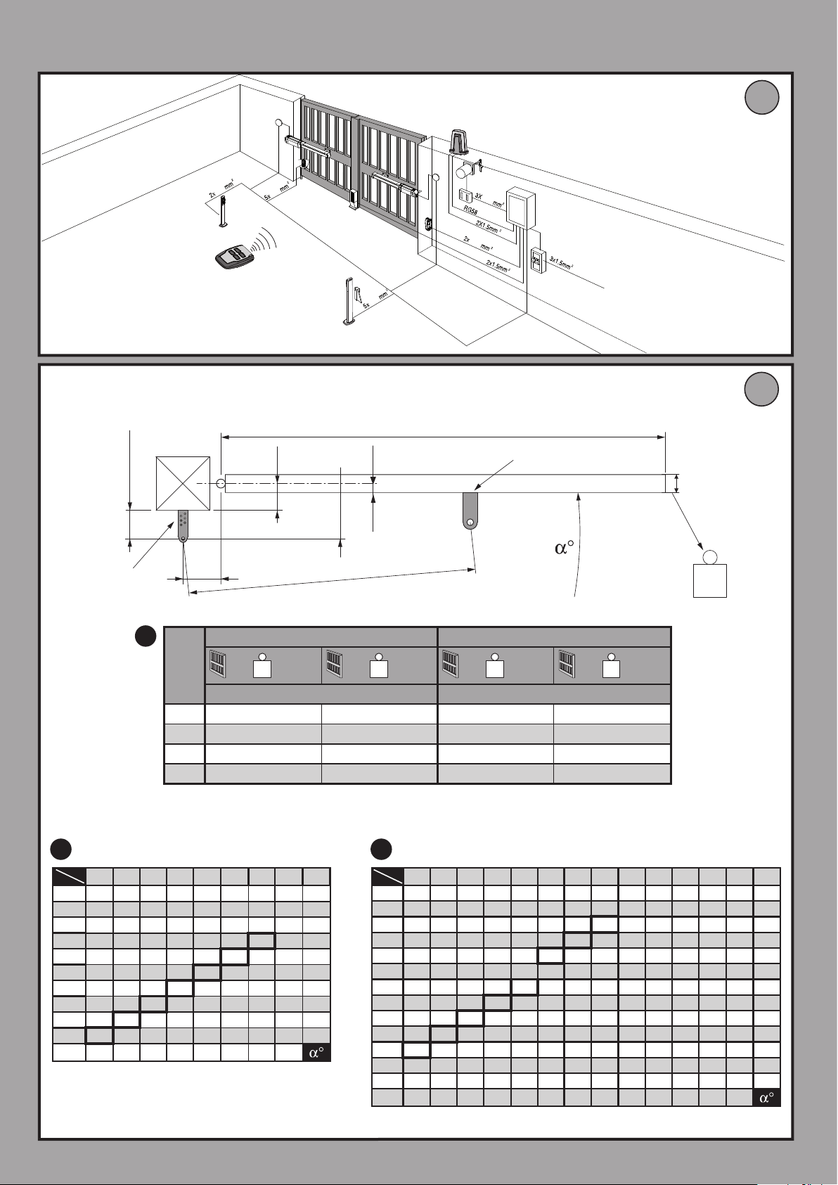
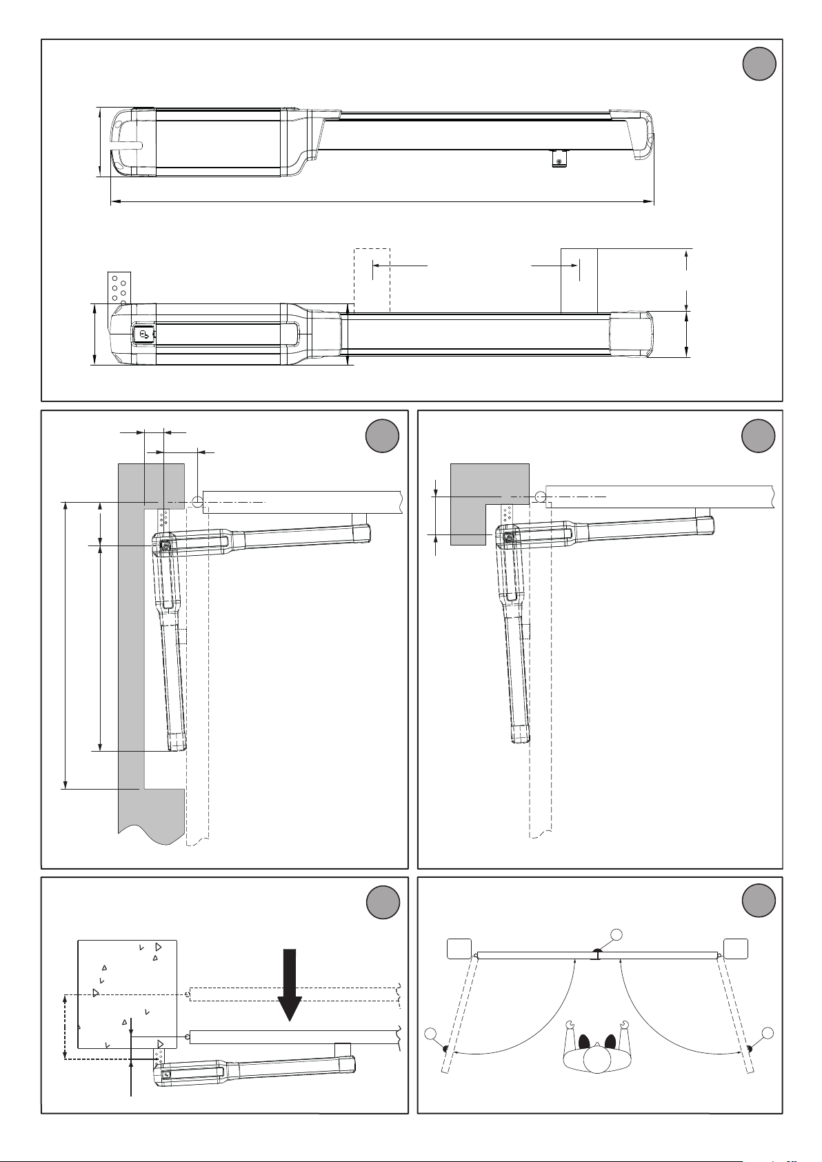
5) INSTALLATION DIAGRAM Fig. B
P rear bracket fastening to pillar
F front fork fastening leaf
a-b distances for determining bracket “P” fastening point
C value of fastening centre-to-centre distance
single-phase 220-230V~ ±10% 50/60 Hz (*)
1,8 m PHOBOS AC A25
3 m PHOBOS AC A50
2,5 m PHOBOS AC A25
5 m PHOBOS AC A50
4000 N (~400 kg) PHOBOS AC A25
5000 N (~500 kg) PHOBOS AC A50
50N (~5kg) PHOBOS AC A25
77N (~7,7kg) PHOBOS AC A50
WEIGHT [kg]
Phobos AC A50 Phobos AC A25
D gate length
X distance from gate axis to corner of pillar
S half door thickness
Z value always greater than 45 mm (b - X)
kg max. weight of leaf
α° leaf opening angle
6) PILLAR FASTENINGS INSTALLATION DISTANCES Fig. B Rif. 2 - 3
6.1) How to read the installation distance tables
Select “a” and “b” according to the angle in degrees α° that the gate has to
open. The optimum “a” and “b” values for 92° opening at constant speed are
highlighted.
If there is too large a dierence between “a” and “b”, the leaf will not travel
smoothly and the pushing or pulling force will uctuate during its stroke.
To respect the opening speed and ensure the controller operates correctly,
it is best to keep the dierence between “a” and “b” as low as possible.
The table has been worked out for A50 mm (PHOBOS AC A50), 20 mm (PHOBOS AC A25) thick medium-size gate. Always check that there is no possible
collision between the gate and the operator.
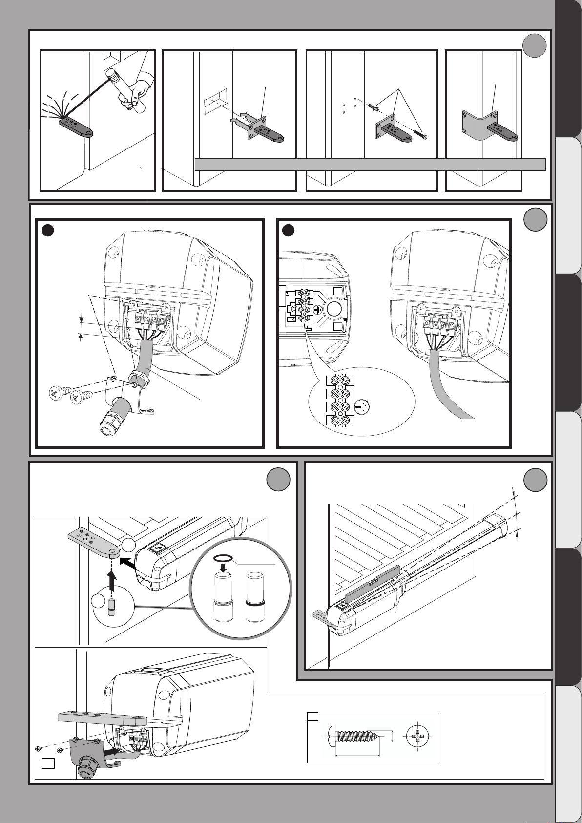
7) FASTENING OF FITTINGS TO PILLAR Fig. C
8) POWER CABLE Fig. D
The board power supply cable must be of the H 05 RN-F type or equivalent.
The equivalent cable must guarantee:
- permanent outside use
- maximum temperature on the cable surface of +50° C
- minimum temperature of -25° C
The wiring of the terminal board must be carried out as shown in Fig. D Ref. 3:
MOT OP = operation 1
MOT CL = operation 2
GND = ear thing
MOT COM = common
Position the cable sheath so that O ring “K” is inserted in its housing in the
base and, leaving the sheath protrude by about J=5 mm (as shown in Fig. D
Ref. 3), close the hatch and x it by means of the 3 screws.
If the motor vibrates but does not rotate, the problem may be:
- Incorrect wiring (see wiring diagram)
- If the leaf moves in the wrong direction, swap over the motor’s start con-
nections in the control unit.
The rst command following a mains power outage should be open STOP
LEAVES.
9) ATTACHING MOTOR TO FASTENING ON PILLAR Fig. E
10) MAXIMUM TILT Fig. F
11) CORRECT INSTALLATION Fig. G
Correct installation entails maintaining a rod stroke margin of approx. 5-10
mm to avoid possible trouble with operation. IMPORTANT: THE FRONT
BRACKET MUST BE FITTED WITH THE SLOTS FACING UP FIG.G RIF.1.
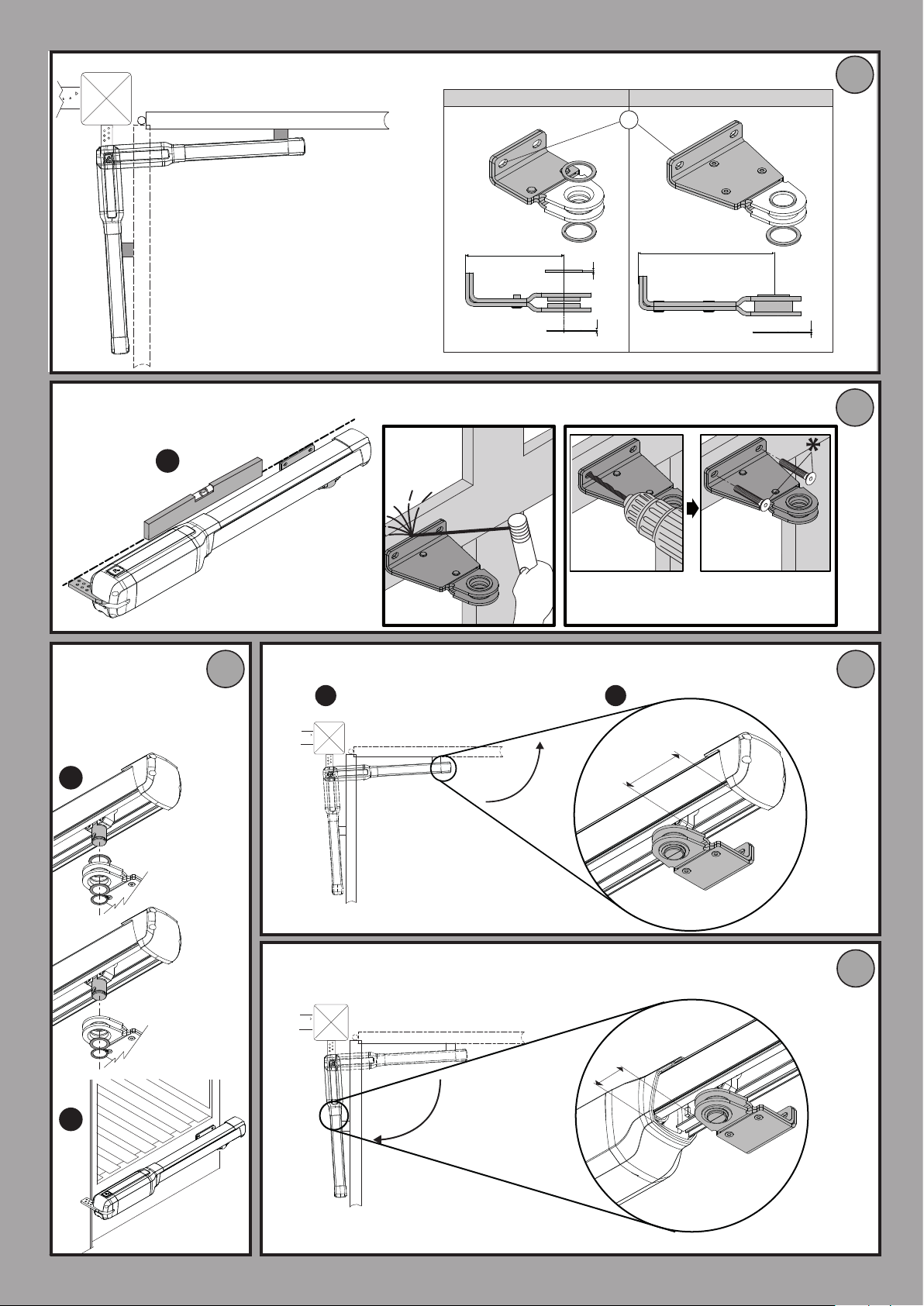
12) FASTENING OF FITTINGS TO LEAF Fig. H
IMPORTANT: the front bracket must be tted with the slots facing up (Fig. G
Ref. 1). Line up the front and rear brackets as shown in Fig. H Ref. 1.
13) OPERATOR ATTACHMENT ON DOOR Fig. I
14) ADJUSTMENT OF THE LIMITING DEVICES Fig. J
The correct adjustment of the limiting devices is obtained by setting the
working time on the control board correctly. Refer to the instructions of
the control board.
WARNING: If the time set on the control unit is insucient, the leaves might
not complete their run.
Slightly increase the working time on the control unit.
15) DIMENSIONS Fig. L
16) TIPS FOR SPECIAL INSTALLATIONS Fig. M, N, O.
With the leaf fully open, create a recess to accommodate the operator.
Fig. M gives the minimum dimensions of the recess for the various PHOBOS
AC A25 - PHOBOS AC A50 models.
If distance “b” is greater than the values given in the installation tables:
- create a recess in the pillar Fig. N
- move the leaf so that it is ush with the pillar Fig. O.
17) LEAF STOPS AT GROUND LEVEL
For the actuator to work properly, it is advisable to use stops “Fig. P Rif. 1” to
stop the leaves both when they are open and closed, as illustrated in Fig. P.
The leaf stops must prevent the actuator rod from reaching the end of its travel.
18) MANUAL OPENING (See USER GUIDE -FIG.Y-).
19) ELECTRIC LOCK
WARNING: In the case of leaves longer than 3m, it is indispensable
to install a solenoid latch.
For electric lock connection, the optional board is required (refer to the
appropriate instruction).
PHOBOS AC A25 - PHOBOS AC A50 - 9
ENGLISH
Page 8

MANUALE D’USO: MANOVRA DI EMERGENZA / USER GUIDE:EMERGENCY OPERATION-
MANUEL D’UTILISATION: DE LA MANŒUVRE D’URGENCE
MANUAL DE USO: MANIOBRA DE EMERGENCIA / GEBRUIKERSHANDLEIDING: NOODMANOEUVRE
/ BEDIENUNGSHANDBUCH: NOTFALLMANÖVER-
FIG. Y
Con Elettroserratura, With electric lock, Avec serrure électrique, Mit Elektroschloß, Con electrocerradura, Met elektrische sluiting.
D812106 00100_06
ON
OFF
ON
1
4
2
5
3
6
7
10
8 9
11
18 - PHOBOS AC A25 - PHOBOS AC A50
Page 9

FIG. Y
Senza Elettroserratura, Without electric lock, Sans serrure électrique, Ohne Elektroschloß, Sin electrocerradura, Zonder elektrische sluiting.
D812106 00100_06
ON
OFF
ON
1 2
4
5
3
6
7
10
8
9
PHOBOS AC A25 - PHOBOS AC A50 - 19
Page 10

AVVERTENZE PER L’UTILIZZATORE ( I )
ATTENZIONE: per la vostra sicurezza dopo
l’attivazione dello sblocco ribloccare l’anta nella
posizione totalmente aperta o totalmente chiusa,
vericare tale posizione dell’anta prima di qualsiasi attivazione dell’automatismo.
ATTENZIONE! Importanti istruzioni di sicurezza.
Leggere e seguire attentamente le Avvertenze e
le Istruzioni che accompagnano il prodotto poiché un uso improprio può causare danni a persone, animali o cose. Conservare le istruzioni per
consultazioni future e trasmetterle ad eventuali
subentranti nell’uso dell’impianto.
Questo prodotto dovrà essere destinato solo
all’uso per il quale è stato espressamente installato. Ogni altro uso è da considerarsi improprio
e quindi pericoloso. Il costruttore non può essere
considerato responsabile per eventuali danni
causati da usi impropri, erronei e irragionevoli.
SICUREZZA GENERALE
Nel ringraziarVi per la preferenza accordata a questo
prodotto, la Ditta è certa che da esso otterrete le
prestazioni necessarie al Vostro uso.
Questo prodotto risponde alle norme riconosciute
della tecnica e della disposizioni relative alla sicurezza
se correttamente installato da personale qualicato
ed esperto (installatore professionale).
L’automazione, se installata ed utilizzata correttamente, soddisfa gli standard di sicurezza nell’uso. Tuttavia
è opportuno osservare alcune regole di comportamento per evitare inconvenienti accidentali:
- Tenere bambini, persone e cose fuori dal raggio
d’azione dell’automazione, in particolare durante
il movimento.
- Non permettere a bambini di giocare o sostare nel
raggio di azione dell’automazione.
- L’apparecchio può essere utilizzato da bambini di
età non inferiore a 8 anni e da persone con ridotte
capacità siche, sensoriali o mentali, o prive di
esperienza o della necessaria conoscenza, purché
sotto sorveglianza oppure dopo che le stesse
abbiano ricevuto istruzioni relative all’uso sicuro
dell’apparecchio e alla comprensione dei pericoli
ad esso inerenti. I bambini non devono giocare con
l’apparecchio. La pulizia e la manutenzione destinata
ad essere eettuata dall’utilizzatore non deve essere
eettuata da bambini senza sorveglianza.
- I bambini devono essere sorvegliati per sincerarsi
che non giochino con l’apparecchio. Non permettere
ai bambini di giocare con i controlli ssi. Tenere i
telecomandi lontani dai bambini.
- Evitare di operare in prossimità delle cerniere o
organi meccanici in movimento.
- Non contrastare il movimento dell’anta e non tentare
di aprire manualmente la porta se non è stato sbloccato l’attuatore con l’apposita manopola di sblocco.
- Non entrare nel raggio di azione della porta o cancello motorizzati durante il loro movimento.
- Non lasciare radiocomandi o altri dispositivi di
comando alla portata dei bambini onde evitare
azionamenti involontari.
- L’attivazione dello sblocco manuale potrebbe causare movimenti incontrollati della porta se in presenza
di guasti meccanici o di condizioni di squilibrio.
- In caso di apritapparelle: sorvegliare la tapparella
in movimento e tenere lontano le persone nché
non è completamente chiusa. Porre cura quando si
aziona lo sblocco se presente, poiché una tapparella
aperta potrebbe cadere rapidamente in presenza di
usura o rotture.
20 - PHOBOS AC A25 - PHOBOS AC A50
D812832 00200_02
- La rottura o l’usura di organi meccanici della porta
(parte guidata), quali ad esempio cavi, molle, supporti, cardini, guide.. potrebbe generare pericoli. Far
controllare periodicamente l’impianto da personale
qualicato ed esperto (installatore professionale)
secondo quanto indicato dall’installatore o dal
costruttore della porta.
- Per ogni operazione di pulizia esterna, togliere
l’alimentazione di rete.
- Tenere pulite le ottiche delle fotocellule ed i dispositivi di segnalazione luminosa. Controllare che rami
ed arbusti non disturbino i dispositivi di sicurezza.
- Non utilizzare l’automatismo se necessita di interventi di riparazione. In caso di guasto o di malfunzionamento dell’automazione, togliere l’alimentazione
di rete sull’automazione, astenersi da qualsiasi tentativo di riparazione o intervento diretto e rivolgersi
solo a personale qualicato ed esperto (installatore
professionale) per la necessaria riparazione o manutenzione. Per consentire l’accesso, attivare lo sblocco
di emergenza (se presente).
- Per qualsiasi intervento diretto sull’automazione o
sull’impianto non previsto dal presente manuale,
avvalersi di personale qualicato ed esperto (installatore professionale).
- Con frequenza almeno annuale far vericare l’integrità
e il corretto funzionamento dell’automazione
da personale qualicato ed esperto (installatore
professionale), in particolare di tutti i dispositivi di
sicurezza.
- Gli interventi d’installazione, manutenzione e riparazione devono essere documentati e la relativa documentazione tenuta a disposizione dell’utilizzatore.
- Il mancato rispetto di quanto sopra può creare
situazioni di pericolo.
DEMOLIZIONE
L’eliminazione dei materiali va fatta rispettando
le norme vigenti. Non gettate il vostro apparecchio scartato, le pile o le batterie usate nei
riuti domestici. Avete la responsabilità di
restituire tutti i vostri riuti da apparecchiature elettriche o elettroniche lasciandoli in un
punto di raccolta dedicato al loro riciclo.
Tutto quello che non è espressamente previsto
nel manuale d’uso, non è permesso. ll buon funzionamento dell’operatore è garantito solo se
vengono rispettate le prescrizioni riportate in
questo manuale. La Ditta non risponde dei danni
causati dall’inosservanza delle indicazioni riportate in questo manuale.
Lasciando inalterate le caratteristiche essenziali
del prodotto, la Ditta si riserva di apportare in
qualunque momento le modiche che essa ritiene convenienti per migliorare tecnicamente,
costruttivamente e commercialmente il prodotto,
senza impegnarsi ad aggiornare la presente pubblicazione.
USER WARNINGS (GB)
WARNING: for your safety, after unlocking the
leaf, relock it in the fully open or closed position
and check that the leaf is in said position before
activating the device.
WARNING! Important safety instructions. Carefully read and comply with the Warnings and Instructions that come with the product as improper
use can cause injury to people and animals and
damage to property. Keep the instructions for future reference and hand them on to any new users.
This product is meant to be used only for the pur-
D812106 00100_06
Page 11

pose for which it was explicitly installed. Any other
use constitutes improper use and, consequently,
is hazardous. The manufacturer cannot be held
liable for any damage as a result of improper,
D812106 00100_06
incorrect or unreasonable use.
GENERAL SAFETY
Thank you for choosing this product. The Firm is
condent that its performance will meet your operating needs.
This product meets recognized technical standards
and complies with safety provisions when installed
correctly by qualied, expert personnel (professional
installer).
If installed and used correctly, the automated system
will meet operating safety standards. Nonetheless, it
is advisable to observe certain rules of behaviour so
that accidental problems can be avoided:
- Keep adults, children and property out of range of
the automated system, especially while it is moving.
- Do not allow children to play or stand within range
of the automated system.
- The unit can be used by children over 8 years old
and by people with reduced physical, sensory or
mental capabilities or with no experience or necessary knowledge on condition they are supervised
or trained about the safe use of the equipment and
understand the risks involved. Children must not
play with the unit. Cleaning and maintenance must
not be performed by unsupervised children.
- Children must be supervised to ensure they do not
play with the device. Do not allow children to play
with the xed controls. Keep remote controls out
of reach of children.
- Do not work near hinges or moving mechanical parts.
- Do not hinder the leaf’s movement and do not attempt to open the door manually unless the actuator
has been released with the relevant release knob.
- Keep out of range of the motorized door or gate
while they are moving.
- Keep remote controls or other control devices out
of reach of children in order to avoid the automated
system being operated inadvertently.
- The manual release’s activation could result in uncontrolled door movements if there are mechanical
faults or loss of balance.
- When using roller shutter openers: keep an eye on
the roller shutter while it is moving and keep people
away until it has closed completely. Exercise care
when activating the release, if such a device is tted,
as an open shutter could drop quickly in the event
of wear or breakage.
- The breakage or wear of any mechanical parts of
the door (operated part), such as cables, springs,
supports, hinges, guides…, may generate a hazard.
Have the system checked by qualied, expert personnel (professional installer) at regular intervals
according to the instructions issued by the installer
or manufacturer of the door.
- When cleaning the outside, always cut o mains power.
- Keep the photocells’ optics and illuminating indicator devices clean. Check that no branches or shrubs
interfere with the safety devices.
- Do not use the automated system if it is in need of
repair. In the event the automated system breaks
down or malfunctions, cut o mains power to the
system; do not attempt to repair or perform any other
work to rectify the fault yourself and instead call in
qualied, expert personnel (professional installer)
to perform the necessary repairs or maintenance. To
allow access, activate the emergency release (where
tted).
D812832 00200_02
- If any part of the automated system requires direct
work of any kind that is not contemplated herein,
employ the services of qualied, expert personnel
(professional installer).
- At least once a year, have the automated system, and
especially all safety devices, checked by qualied,
expert personnel (professional installer) to make
sure that it is undamaged and working properly.
- A record must be made of any installation, maintenance and repair work and the relevant documentation kept and made available to the user on request.
- Failure to comply with the above may result in hazardous situations.
SCRAPPING
Materials must be disposed of in accordance
with the regulations in force. Do not throw
away your discarded equipment or used batteries with household waste. You are responsible for taking all your waste electrical and
electronic equipment to a suitable recycling
centre.
Anything that is not explicitly provided for in the
user guide is not allowed. The operator’s proper
operation can only be guaranteed if the instructions given herein are complied with. The Firm shall
not be answerable for damage caused by failure
to comply with the instructions featured herein.
While we will not alter the product’s essential
features, the Firm reserves the right, at any time,
to make those changes deemed opportune to
improve the product from a technical, design or
commercial point of view, and will not be required
to update this publication accordingly.
PHOBOS AC A25 - PHOBOS AC A50 - 21
Page 12

ITALY
 Loading...