

Page 1
Quick Start Guide
2600-VCO
Legendary Analog VCO Module for Eurorack
V 1.0
Page 2

2 3Quick Start Guide260 0-VCO
LEGAL DISCLAIMER
Music Tribe accepts no liability for any loss
which may be suered by any person who
relies either wholly or in part upon any
description, photograph, or statement
contained herein. Technical specications,
appearances and other information are
subject to change without notice. All
trademarks are the property of their
respective owners. Midas, Klark Teknik,
Lab Gruppen, Lake, Tannoy, Turbosound,
TC Electronic, TC Helicon, Behringer, Bugera,
Oberheim, Auratone, Aston Microphones
and Coolaudio are trademarks or registered
trademarks of Music Tribe Global
Brands Ltd. © Music Tribe Global Brands
Ltd. 2021 All rights reserved.
LIMITED WARRANTY
For the applicable warranty terms and
conditions and additional information
regarding Music Tribe’s Limited Warranty,
please see complete details online at
musictribe.com/warranty.
NEGACIÓN LEGAL
Music Tribe no admite ningún tipo de
responsabilidad por cualquier daño o
pérdida que pudiera sufrir cualquier persona
por conar total o parcialmente en la
descripciones, fotografías o armaciones
contenidas en este documento. Las
especicaciones técnicas, imágenes y
otras informaciones contenidas en este
documento están sujetas a modicaciones
sin previo aviso. Todas las marcas comerciales
que aparecen aquí son propiedad de sus
respectivos dueños. Midas, Klark Teknik,
Lab Gruppen, Lake, Tannoy, Turbosound,
TC Electronic, TC Helicon, Behringer, Bugera,
Oberheim, Auratone, Aston Microphones
y Coolaudio son marcas comerciales o
marcas registradas de Music Tribe Global
Brands Ltd. © Music Tribe Global Brands Ltd.
2021 Reservados todos los derechos.
GARANTÍA LIMITADA
Si quiere conocer los detalles y condiciones
aplicables de la garantía así como
información adicional sobre la Garantía
limitada de Music Tribe, consulte online
toda la información en la web
musictribe.com/warranty.
DÉNI LÉGAL
Music Tribe ne peut être tenu pour
responsable pour toute perte pouvant
être subie par toute personne se ant en
partie ou en totalité à toute description,
photographie ou armation contenue
dans ce document. Les caractéristiques,
l’apparence et d’autres informations
peuvent faire l’objet de modications
sans notication. Toutes les marques
appartiennent à leurs propriétaires
respectifs. Midas, Klark Teknik, Lab Gruppen,
Lake, Tannoy, Turbosound, TC Electronic,
TC Helicon, Behringer, Bugera, Oberheim,
Auratone, Aston Microphones et Coolaudio
sont des marques ou marques déposées de
Music Tribe Global Brands Ltd. © Music Tribe
Global Brands Ltd. 2021 Tous droits réservés.
GARANTIE LIMITÉE
Pour connaître les termes et conditions
de garantie applicables, ainsi que les
informations supplémentaires et
détaillées sur la Garantie Limitée de
Music Tribe, consultez le site Internet
musictribe.com/warranty.
HAFTUNGSAUSSCHLUSS
Music Tribe übernimmt keine Haftung für
Verluste, die Personen entstanden sind, die
sich ganz oder teilweise auf hier enthaltene
Beschreibungen, Fotos oder Aussagen
verlassen haben. Technische Daten,
Erscheinungsbild und andere Informationen
können ohne vorherige Ankündigung
geändert werden. Alle Warenzeichen sind
Eigentum der jeweiligen Inhaber. Midas,
Klark Teknik, Lab Gruppen, Lake, Tannoy,
Turbosound, TC Electronic, TC Helicon,
Behringer, Bugera, Oberheim, Auratone,
Aston Microphones und Coolaudio
sind Warenzeichen oder eingetragene
Warenzeichen der Music Tribe Global Brands
Ltd. © Music Tribe Global Brands Ltd. 2021
Alle Rechte vorbehalten.
BESCHRÄNKTE GARANTIE
Die geltenden Garantiebedingungen und
zusätzliche Informationen bezüglich der
von Music Tribe gewährten beschränkten
Garantie nden Sie online unter
musictribe.com/warranty.
LEGAL RENUNCIANTE
O Music Tribe não se responsabiliza por
perda alguma que possa ser sofrida por
qualquer pessoa que dependa, seja de
maneira completa ou parcial, de qualquer
descrição, fotograa, ou declaração aqui
contidas. Dados técnicos, aparências
e outras informações estão sujeitas a
modicações sem aviso prévio. Todas
as marcas são propriedade de seus
respectivos donos. Midas, Klark Teknik,
Lab Gruppen, Lake, Tannoy, Turbosound,
TC Electronic, TC Helicon, Behringer, Bugera,
Oberheim, Auratone, Aston Microphones
e Coolaudio são marcas ou marcas
registradas do Music Tribe Global Brands
Ltd. © Music Tribe Global Brands Ltd.
2021 Todos direitos reservados.
GARANTIA LIMITADA
Para obter os termos de garantia aplicáveis
e condições e informações adicionais a
respeito da garantia limitada do Music Tribe,
favor vericar detalhes na íntegra através do
website musictribe.com/warranty.
DISCLAIMER LEGALE
Music Tribe non si assume alcuna
responsabilità per eventuali danni che
possono essere subiti da chiunque si adi
in tutto o in parte a qualsiasi descrizione,
fotograa o dichiarazione contenuta
qui. Speciche tecniche, aspetti e altre
informazioni sono soggette a modiche
senza preavviso. Tutti i marchi sono di
proprietà dei rispettivi titolari. Midas,
Klark Teknik, Lab Gruppen, Lake, Tannoy,
Turbosound, TC Electronic, TC Helicon,
Behringer, Bugera, Oberheim, Auratone,
Aston Microphones e Coolaudio sono marchi
o marchi registrati di Music Tribe Global
Brands Ltd. © Music Tribe Global Brands
Ltd. 2021 Tutti i diritti riservati.
GARANZIA LIMITATA
Per i termini e le condizioni di garanzia
applicabili e le informazioni aggiuntive
relative alla garanzia limitata di Music Tribe,
consultare online i dettagli completi su
musictribe.com/warranty.
WETTELIJKE ONTKENNING
Music Tribe aanvaardt geen
aansprakelijkheid voor enig verlies dat
kan worden geleden door een persoon die
geheel of gedeeltelijk vertrouwt op enige
beschrijving, foto of verklaring hierin.
Technische specicaties, verschijningen
en andere informatie kunnen zonder
voorafgaande kennisgeving worden
gewijzigd. Alle handelsmerken zijn
eigendom van hun respectievelijke
eigenaren. Midas, Klark Teknik, Lab
Gruppen, Lake, Tannoy, Turbosound,
TC Electronic, TC Helicon, Behringer, Bugera,
Oberheim, Auratone, Aston Microphones
en Coolaudio zijn handelsmerken of
gedeponeerde handelsmerken van Music
Tribe Global Brands Ltd. © Music Tribe
Global Brands Ltd. 2021 Alle rechten
voorbehouden.
BEPERKTE GARANTIE
Voor de toepasselijke garantievoorwaarden
en aanvullende informatie met betrekking
tot de beperkte garantie van Music Tribe,
zie de volledige details online op
musictribe.com/warranty.
FRISKRIVNINGSKLAUSUL
Music Tribe tar inget ansvar för någon
förlust som kan drabbas av någon person
som helt eller delvis förlitar sig på någon
beskrivning, fotogra eller uttalande
som nns här. Tekniska specikationer,
utseenden och annan information kan
ändras utan föregående meddelande. Alla
varumärken tillhör respektive ägare. Midas,
Klark Teknik, Lab Gruppen, Lake, Tannoy,
Turbosound, TC Electronic, TC Helicon,
Behringer, Bugera, Oberheim, Auratone,
Aston Microphones och Coolaudio är
varumärken eller registrerade varumärken
som tillhör Music Tribe Global Brands Ltd.
© Music Tribe Global Brands Ltd. 2021 Alla
Rättigheter reserverade.
BEGRÄNSAD GARANTI
För tillämpliga garantivillkor och ytterligare
information om Music Tribes begränsade
garanti, se fullständig information online på
musictribe.com/warranty.
ZASTRZEŻENIA PRAWNE
Music Tribe nie ponosi odpowiedzialności
za jakiekolwiek straty, które mogą ponieść
osoby, które polegają w całości lub w
części na jakimkolwiek opisie, fotograi
lub oświadczeniu zawartym w niniejszym
dokumencie. Specykacje techniczne,
wygląd i inne informacje mogą ulec zmianie
bez powiadomienia. Wszystkie znaki
towarowe są własnością ich odpowiednich
właścicieli. Midas, Klark Teknik,
Lab Gruppen, Lake, Tannoy, Turbosound,
TC Electronic, TC Helicon, Behringer, Bugera,
Oberheim, Auratone, Aston Microphones
i Coolaudio są znakami towarowymi lub
zastrzeżonymi znakami towarowymi rmy
Music Tribe Global Brands Ltd. © Music Tribe
Global Brands Ltd. 2021 Wszystkie prawa
zastrzeżone.
OGRANICZONA
GWARANCJA
Aby zapoznać się z obowiązującymi
warunkami gwarancji i dodatkowymi
informacjami dotyczącymi ograniczonej
gwarancji Music Tribe, zapoznaj się ze
wszystkimi szczegółami w trybie online pod
adresem musictribe.com/warranty.
Page 3
4 5Quick Start Guide260 0-VCO
2600-VCO
(1)
(3)
(10)
(2)
(4)
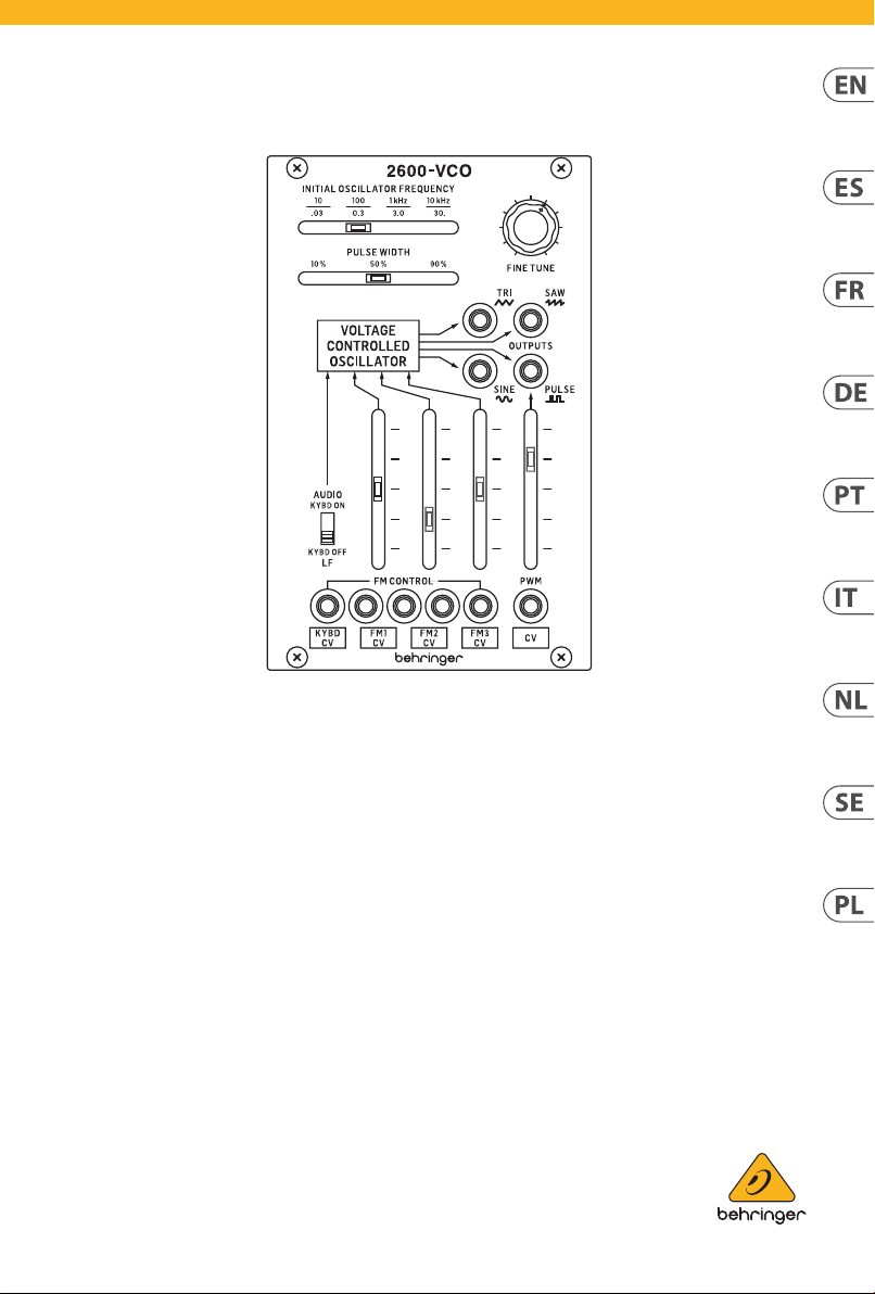
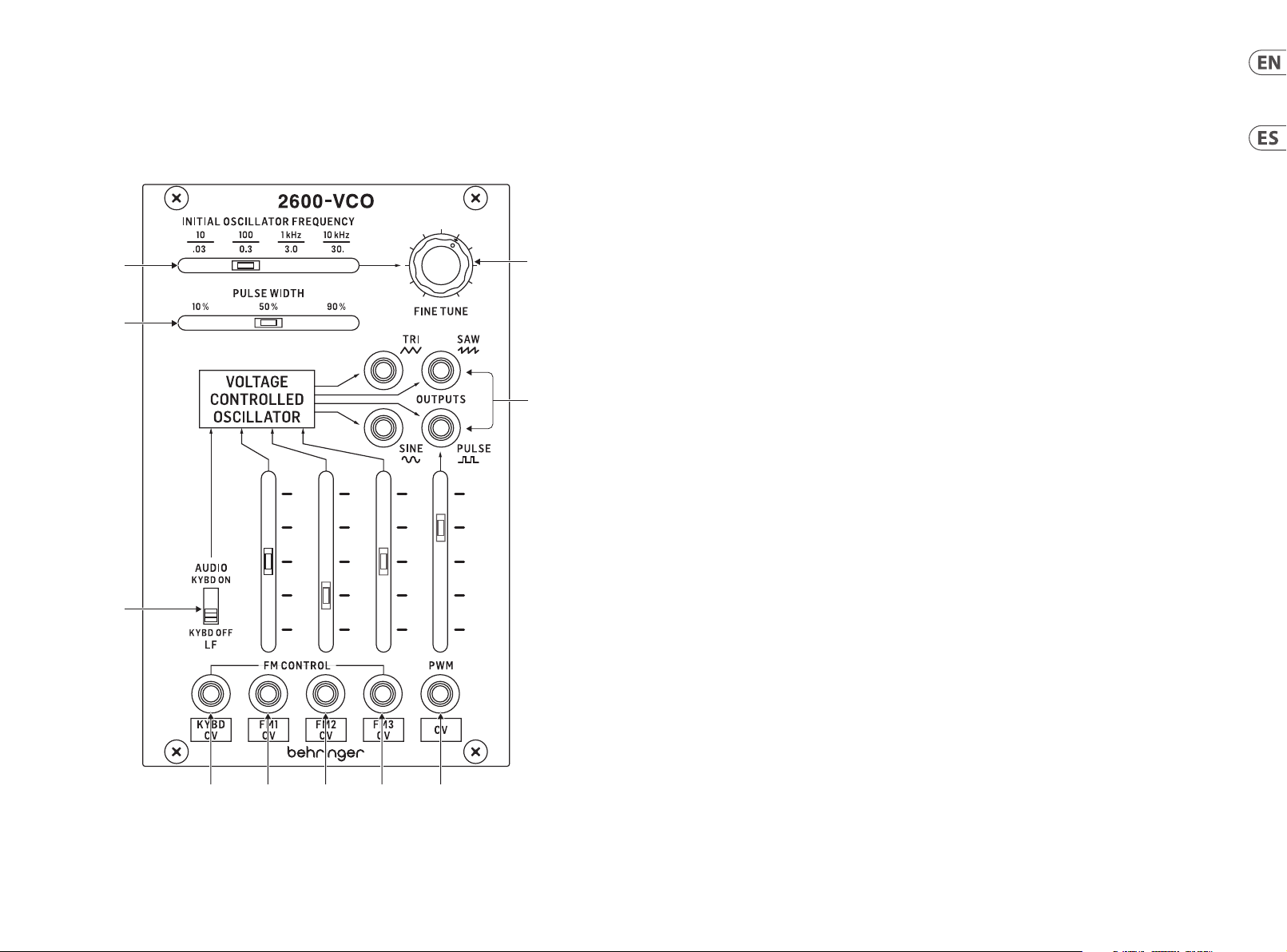
(EN) Step 2: Controls
(1) INITIAL OSCILLATOR FREQUENCY – selects
the initial frequency of the VCO. In Audio mode
the range is 10 Hz to 10 kHz; in Low Frequency
mode (LF) the range is 0.03 Hz to 30 Hz.
(2) FINE TUNE – allows the 2600 VCO to be tuned
to other VCOs or instruments, the control has a
range of ±0.4 octaves.
(3) PULSE WIDTH – allows manual control over
the width of the pulse waveform and has a
range from 10% to 90%
(4) OUTPUTS – separate outputs for sine, triangle,
sawtooth and pulse waveforms. All are
available simultaneously.
(5) KEYBOARD CV INPUT – accepts control
voltages from a keyboard or MIDI/CV converter
in the range 0 V – 10 V
(6) (7), (8) - FM INPUTS AND LEVELS – input
for frequency modulation of the VCO plus
attenuators to control the level of modulation
(9) PULSE WIDTH MODULATION INPUT AND
LEVEL – input for an external source of
modulation of the width of the pulse waveform
plus attenuator to control the level of modulation
(10) KEYBOARD ON/OFF SWITCH – allows the
keyboard voltage to be switched o which puts
the VCO into Low Frequency mode
(ES) Paso 2: Controles
(1) INITIAL OSCILLATOR FREQUENCY – esto le
permite elegir la frecuencia inicial del VCO.
En el modo audio el rango es de 10 Hz a 10 KHz;
en el modo de baja frecuencia (LF) el rango será
de 0.03 Hz a 30 Hz
(2) FINE TUNE – este control permite anar
el 2600 VCO a otros VCOs o instrumentos;
el control tiene un rango de ±0.4 octavas.
(3) PULSE WIDTH – permite el control manual
de la amplitud de la forma de onda de pulso y
tiene un rango de 10% a 90%
(4) OUTPUTS – salidas independientes para las
formas de onda sinusoidal, triangular, diente de
sierra y pulso. Todas ellas están disponibles de
forma simultánea
(5) ENTRADA KYBD CV – esta entrada acepta
voltajes de control de teclado o de un
convertidor MIDI/CV en un rango de 0 V – 10 V
(6) (7), (8) - ENTRADAS Y NIVELES FM – entradas
para la modulación de frecuencia del VCO
más atenuadores para controlar el nivel de la
modulación
(9) ENTRADA Y NIVEL PWM (MODULACIÓN DE
AMPLITUD DE PULSO) – entrada para una
fuente externa de modulación de la amplitud
de la forma de onda de pulso más atenuador
para controlar el nivel de la modulación
(6)(5) (7) (8) (9)
(10) INTERRUPTOR ON/OFF DE TECLADO
– permite que el voltaje del teclado sea
desactivado, lo que hará que el VCO quede en el
modo de baja frecuencia
Page 4

6 7Quick Start Guide260 0-VCO
2600-VCO
(FR) Etape 2 : Réglages
(1) INITIAL OSCILLATOR FREQUENCY – permet
de sélectionner la fréquence initiale du VCO.
En mode Audio, la fréquence peut varier entre
10 Hz et 10 KHz ; en mode LF, la fréquence peut
varier entre 0,3 Hz et 30 Hz
(2) FINE TUNE – permet d’accorder le VCO du 2600
par rapport à d’autres VCO ou instruments;
la plage de réglage est de ±0.4 octave
(3) PULSE WIDTH – permet de régler
manuellement la largeur de l’onde pulse
(de 10% à 90%)
(4) OUTPUTS – sorties séparées pour les ondes
sinusoïdale, triangulaire, en dent de scie et pulse.
Toutes sont disponibles simultanément
(5) ENTRÉES KEYBOARD CV – peut recevoir une
tension de contrôle de 0 V à 10 V transmise par
un clavier ou un convertisseur MIDI/CV
(6) (7), (8) - ENTRÉES ET RÉGLAGES FM – entrées
pour la modulation de la fréquence du VCO et
atténuateurs du niveau de modulation
(9) ENTRÉE ET RÉGLAGE PWM – entrée pour une
source externe de modulation de la largeur
de l’onde pulse et atténuateur du niveau de
modulation
(10) INTERRUPTEUR KYBD ON/OFF – permet de
désactiver la tension du clavier et de placer le
VCO en mode LF
(DE) Schritt 2: Bedienelemente
(1) INITIAL OSCILLATOR FREQUENCY – wählt
die anfängliche Frequenz des VCOs. Im
Audiomodus beträgt der Bereich 10 Hz bis
10 kHz. Im Low Frequency-Modus (LF) beträgt
der Bereich 0.03 Hz bis 30 Hz.
(2) FINE TUNE – Zum Abstimmen des 2600 VCOs
auf andere VCOs oder Instrumente. Der Regler
hat einen Bereich von ±0.4 Oktaven.
(3) PULSE WIDTH – ermöglicht die manuelle
Kontrolle über die Breite der Pulswellenform
über einen Bereich von 10 % bis 90 %.
(4) OUTPUTS – separate Ausgänge für Sinus-,
Dreieck-, Sägezahn- und Pulswellenformen.
Alle sind gleichzeitig verfügbar.
(5) KEYBOARD CV-EINGANG – akzeptiert
Steuerspannungen von Tastaturen oder MIDI/
CV-Wandlern im Bereich 0 V - 10 V.
(6) (7), (8) - FM-EINGANG UND -PEGEL –
Eingang für die Frequenzmodulation des VCOs
sowie Dämpfungsglied zur Steuerung des
Modulationspegels.
(9) PULSE WIDTH MODULATION-EINGANG
UND -PEGEL – Eingang für eine externe
Quelle zum Modulieren der Pulswellenbreite
sowie Dämpfungsglied zur Steuerung des
Modulationspegels.
(10) KEYBOARD EIN/AUS-SCHALTER – ermöglicht
das Ausschalten der Tastaturspannung,
wodurch der VCO in den Low Frequency-Modus
geschaltet wird.
(PT) Passo 2: Controles
(1) INITIAL OSCILLATOR FREQUENCY – seleciona
a frequência inicial do VCO. No modo ‘audio’, o
alcance é de 10 Hz a 10 KHz; no modo de baixa
frequência (LF) o alcance é de 0.03 Hz a 30 Hz
(2) FINE TUNE – permite que o 2600 VCO seja
sintonizado a outros VCOs ou instrumentos,
o controle tem um alcance de ±0.4 oitavas.
(3) PULSE WIDTH – possibilita controle manual da
amplitude da forma de onda pulso com alcance
entre 10% e 90%
(4) OUTPUTS – separa saídas de formas de onda
senoidais, triangulares, dente de serra e pulso.
Todas disponíveis simultaneamente
(5) KEYBOARD CV INPUT – aceita tensão de
controle proveniente de um teclado ou
conversor MIDI/CV em uma gama de 0 V – 10 V
(6) (7), (8) - ENTRADAS E NÍVEIS FM – entrada
para a modulação de frequência do VCO
além de atenuadores para o controle do nível
de modulação
(9) ENTRADA E NÍVEL DE MODULAÇÃO DE
AMPLITUDE DE PULSO – entrada para fonte
de modulação externa da amplitude da forma
de onda pulso além do atenuador de controle do
nível de modulação
(10) INTERRUPTOR ON/OFF DO TECLADO –
possibilita que a tensão do teclado seja
desligada, o que coloca o VCO no modo de
baixa frequência.
(IT) Passo 2: Controlli
(1) INITIAL OSCILLATOR FREQUENCY – seleziona
la frequenza iniziale del VCO. Nel modo audio
la gamma va da 10 Hz a 10 KHz; nel modo Low
Frequency (LF) la gamma è da 0.03 Hz a 30 Hz
(2) FINE TUNE – permette di accordare il 2600 VCO
con altri VCO o strumenti, il controllo ha una
gamma di ±0.4 di ottava.
(3) PULSE WIDTH – consente il controllo manuale
della larghezza della forma d’onda impulsiva e
ha un intervallo dal 10% al 90%
(4) OUTPUTS – uscite separate per forma
d’onda sinusoidale, triangolare, a dente
di sega e impulsiva. Sono tutte disponibili
contemporaneamente
(5) INGRESSO KEYBOARD CV – accetta tensioni
di controllo da tastiera o convertitore MIDI/CV
nell’intervallo 0 V – 10 V
(6) (7), (8) - INGRESSO & LIVELLI FM CONTROL
– ingressi per la modulazione di frequenza del
VCO e attenuatori per il controllo del livello di
modulazione
(9) INGRESSO & LIVELLO PULSE WIDTH
MODULATION – ingresso per una sorgente
esterna di modulazione dell’ampiezza della
forma d’onda impulsiva e attenuatore per
controllare il livello di modulazione
(10) INTERRUTTORE KEYBOARD ON/OFF –
permette di escludere la tensione della tastiera;
ciò commuta il VCO nel modo Low Frequency
Page 5

8 9Quick Start Guide260 0-VCO
2600-VCO
(NL) Stap 2: Bediening
(1) INITIAL OSCILLATOR FREQUENCY –
Selecteer t de beginfrequentie van de VCO. In
audiomodus is het bereik 10 Hz tot 10 KHz; in
lage frequentiemodus (LF) bedraagt het bereik
0.03 Hz tot 30 Hz
(2) FINE TUNE – Hiermee kan de 2600 VCO met
andere VCO’s of instrumenten worden gestemd.
De regelaar heeft een bereik van ±0.4 octaven.
(3) PULSE WIDTH – geeft handmatige controle
over de breedte van de pulsgolfvorm en heeft
een bereik van 10% tot 90%
(4) OUTPUTS – aparte uitgangen voor sinus-,
driehoek-, zaagtand- en pulsgolfvormen. Alle
golfvormen zijn tegelijkertijd beschikbaar
(5) KEYBOARD CV INGANG – accepteert
stuurspanning vanaf het keyboard of de MIDI/
CV-converter in het bereik 0 V – 10 V.
(6) (7), (8) - FM INGANGEN EN NIVEAUS –
ingangen voor frequentiemodulatie van de VCO
plus attenuators om het modulatieniveau te
regelen
(9) PULSE WIDTH MODULATION INGANG EN
NIVEAU – ingang voor een externe modulatie
van de breedte van de pulsgolfvorm plus
attenuator om het modulatieniveau te regelen
(10) KEYBOARD AAN/UIT-SCHAKELAAR - zorgt
ervoor dat de toetsenbordspanning kan worden
uitgeschakeld, waardoor de VCO naar lage
frequentiemodus wordt omgeschakeld.
(SE) Steg 2: Kontroller
(1) INITIAL OSCILLATOR FREQUENCY – väljer
den initiala frekvensen för VCO:n. I ljudläge är
intervallet 10 Hz till 10 kHz, i lågfrekvensläge
(LF) är intervallet 0,03 Hz till 30 Hz
(2) FINE TUNE – gör att 2600 VCO kan stämmas
efter andra VCO:er eller instrument, kontrollen
har ett omfång på ±0.4 oktaver.
(3) PULSE WIDTH – möjliggör manuell styrning av
pulsvågformens bredd och har ett omfång från
10% till 90%
(4) UTGÅNGAR – separata utgångar för sinus-,
triangel-, sågtand- och pulsvågformer. Alla är
tillgängliga samtidigt
(5) KEYBOARD CV-INGÅNG – tar emot
styrspänningar från klaviatur eller MIDI/
CV-omvandlare i intervallet 0 V–10 V
(6) (7), (8) - FM-INGÅNGAR OCH -NIVÅER –
ingång för frekvensmodulering av VCO:n plus
dämpare för att styra modulationsnivån
(9) INGÅNG OCH NIVÅ FÖR
PULSBREDDSMODULATION – ingång
för en extern källa för modulation av
pulsvågformens bredd plus dämpare för att
styra modulationsnivån
(10) PÅ/AV-OMKOPPLARE FÖR KLAVIATUR – gör
att klaviaturens spänning kan stängas av, vilket
ställer in VCO:n på lågfrekvensläge
(PL) Steg 2: Kontroller
(1) INITIAL OSCILLATOR FREQUENCY – wybiera
pierwotną częstotliwość VCO. W trybie audio
przedział wynosi od 10 Hz do 10KHz; w trybie
niskich częstotliwości (LF) przedział wynosi od
0.03 Hz do 30 Hz.
(2) FINE TUNE – pozwala 2600 VCO na dostrojenie
do innych VCO lub instrumentów. Ta regulacja
ma przedział ±0.4 oktawy.
(3) PULSE WIDTH – pozwala na ręczną kontrolę
nad szerokością kształtu fali pulsu. Ta regulacja
ma przedział od 10% do 90%.
(4) OUTPUTS – osobne wyjścia dla fal
sinusoidalnych, trójkątnych, piłokształtnych
oraz pulsu. Wszystkie są dostępne
jednocześnie.
(5) WEJŚCIE KEYBOARD CV – przyjmuje napięcia
kontrolne z klawiatury lub konwertera MIDI/CV
w przedziale 0 V – 10 V.
(6) (7), (8) - WEJŚCIA I POZIOMY FM – wejście
dla modulacji częstotliwości VCO oraz tłumiki
pozwalające na kontrolowanie poziomu
modulacji.
(9) WEJŚCIE I POZIOM MODULACJI SZEROKOŚCI
PULSU – wejście dla zewnętrznego źródła
modulacji szerokości kształtu fali pulsu oraz
tłumik pozwalający na kontrolę poziomu
modulacji.
(10) PRZEŁĄCZNIK KEYBOARD ON/OFF – pozwala
na wyłączenie napięcia klawiatury, co przełącza
VCO na tryb niskich częstotliwości.
Page 6

10 11Quick Start Guide2600 -VCO
Power Connection
The 2600 -VCO module comes with t he required power c able for connec ting to a standard Eu rorack power supp ly system. Follow t hese
steps to con nect the module t o your Eurorack cas e.
1. Turn the power supp ly or rack case power o and disconnec t the power cable.
2. Insert the 16-pi n connector on th e power cable into the s ocket on the power sup ply or rack case. Th e connector has a ta b that will
align with t he gap in the socket, s o it cannot be inser ted incorrec tly. If the power suppl y does not have a keyed soc ket, be sure to orient
pin 1 (-12 V) with the red st ripe on the cable.
3. Insert the 10- pin connector in to the socket on the ba ck of the module. The co nnector has a tab t hat will align with th e socket for
correct orientation.
4. After both ends of t he power cable have be en securely at tached, you may mount t he module in a case an d turn on the power sup ply.
Installation
The neces sary screws ar e included with th e module for mount ing in a Eurorack cas e. Connect the powe r cable before mo unting.
Dependi ng on the rack case, th ere may be a series of xed holes spaced 2 HP ap art along the leng th of the case, or a tr ack that allows
individ ual threaded plate s to slide along the leng th of the case. The f ree-moving thr eaded plates allow pr ecise position ing of the module,
but each pl ate should be positi oned in the approxi mate relation to the mo unting holes in you r module before at taching the scr ews.
Hold the mo dule against the Eur orack rails so that e ach of the mounting ho les are aligned wi th a threaded rail or t hreaded plate. Att ach
the screw s part way to star t, which will allow s mall adjustment s to the positionin g while you get them all a ligned. After th e nal position
has been es tablished, tigh ten the screws dow n.
Conexión Eléctrica
El módulo vi ene con el cable de ali mentación neces ario para conec tarse a un siste ma de suministro de e nergía Eurorack e stándar. Siga
estos pa sos para conec tar la alimentació n al módulo. Es más fác il realizar est as conexiones ant es de que el módulo se hay a montado en
una caja de r ack.
1. Apague la fue nte de alimentació n o la caja del bastido r y desconecte e l cable de alimentac ión.
2. Inserte el con ector de 16 clavijas d el cable de aliment ación en la toma de la f uente de alimentac ión o en la caja del bas tidor. El conecto r
tiene una pe staña que se alin eará con el espaci o en el zócalo, por lo que n o se puede inser tar incorrec tamente. Si la fuen te de alimentació n
no tiene un en chufe con llave, ase gúrese de orient ar el pin 1 (-12 V ) con la raya roja en el c able.
3. Inserte el cone ctor de 10 pines en el zó calo en la parte po sterior del módu lo. El conector tie ne una pestaña que s e alineará con el
enchufe para una orientación correcta.
4. Una vez que ambos ex tremos del cable d e alimentación se h ayan conectado d e forma segura, pu ede montar el módu lo en una caja y
encender la fuente de alimentación.
Instalación
Los tornil los necesarios s e incluyen con el mód ulo para su montaje en u na caja Eurorack. C onecte el cable d e alimentación ant es
del montaje.
Dependi endo de la caja del bas tidor, puede haber una s erie de oricio s jos separados 2 HP a l o largo de la caja, o una pis ta que permita
que las plac as roscadas indi viduales se desli cen a lo largo de la caja. L as placas roscad as de movimiento libr e permiten un posic ionamiento
precis o del módulo, pero cad a placa debe coloc arse en una relació n aproximada con los o ricios de monta je en su módulo antes de co locar
los tornillos.
Sosteng a el módulo contra lo s rieles Eurorac k de modo que cada uno de l os oricios de mon taje esté alineado c on un riel o placa ros cada.
Coloque lo s tornillos parcia lmente para comenz ar, lo que permitirá pe queños ajustes e n la posición mientr as los alinea todos. U na vez
establecida la posición nal, apriete los tornillos.
Page 7

12 13Quick Start Guide2600 -VCO
Connexion Électrique
Le module es t livré avec le câbl e d’alimentation req uis pour la connexi on à un système d’alime ntation standa rd Eurorack. Suive z ces
étapes p our connecter l ’a limentation au mo dule. Il est plus fac ile d’eectuer ces c onnexions avant qu e le module n’ait été monté da ns un
boîtier d e rack.
1. Mettez le bl oc d’alimentation ou l e boîtier de rack ho rs tension et débr anchez le câble d’alim entation.
2. Insérez le connec teur à 16 broches du câ ble d’alimentation d ans la prise du bloc d ’a limentation ou du bo îtier du rack. Le co nnecteur
a une langue tte qui s’alignera ave c l’espace dan s la prise, de sorte q u’il ne peut pas êtr e inséré de manière in correcte. Si le blo c
d’alimentat ion n’a pas de prise à clé, vei llez à orienter la bro che 1 (-12 V) ave c la bande rouge sur le c âble.
3. Insérez le conne cteur à 10 broches da ns la prise à l’arrière d u module. Le connec teur a une languett e qui s’alignera avec la pri se pour
une orientation correcte.
4. Une fois que les deux e xtrémités du c âble d’alimentatio n ont été solidement xées, vous pouvez m onter le module dans un b oîtier et
allumer l’alimentation.
Installation
Les vis néc essaires sont in cluses avec le modul e pour le montage dan s un boîtier Eurora ck. Connectez l e câble d’alimentati on avant
le montage.
Selon le ca s de rack, il peut y avoi r une série de trous xes espacés de 2 HP sur la l ongueur du cas, ou une p iste qui permet au x plaques
letées i ndividuelles de g lisser le long de la long ueur du cas. Les plaq ues letées à dépla cement libre perme ttent un positi onnement
précis du m odule, mais chaque pl aque doit être posi tionnée approx imativement par ra pport aux trou s de montage de votre m odule avant
de xer les v is.
Maintene z le module contre les r ails Eurorack de so rte que chacun de s trous de montage s oit aligné avec un rail leté ou une plaque
letée. Fi xez les vis parti ellement pour comm encer, ce qui permett ra de petits ajus tements au posit ionnement pendan t que vous les
alignere z tous. Une fois la posi tion nale établi e, serrez les vis ver s le bas.
Netzanschluss
Das Modul wird mit dem erforderlichen Stromkabel für den Anschluss an ein Standard-Eurorack-Stromversorgungssystem geliefert.
Befolgen Sie diese Schritte, um das Modul mit Strom zu versorgen. Es ist einfacher, diese Verbindungen herzustellen, bevor das Modul in
ein Rackgehäuse eingebaut wurde.
1. Schalten Sie da s Netzteil ode r das Rackgehäuse aus u nd ziehen Sie das Net zkabel ab.
2. Stecken Sie den 16-pol igen Stecker am Netz kabel in die Buchse a m Netzteil ode r im Rack-Gehäuse. De r Anschluss verf ügt über eine
Lasche, d ie an der Lücke in der Buch se ausgerichte t ist, sodass sie nic ht falsch einges etzt werden ka nn. Wenn das Netztei l keine
Schlüss elbuchse hat, ach ten Sie darauf, Pin 1 (-12 V) mit dem roten Stre ifen am Kabel ausz urichten.
3. Stecken Sie den 10-p oligen Stecker in die Bu chse auf der Rück seite des Moduls. D er Anschluss ver fügt über eine La sche, die zur
korrekten Ausrichtung an der Buchse ausgerichtet wird.
4. Nachdem beide Enden des Netzkabels fest angeschlossen wurden, können Sie das Modul in einem Gehäuse montieren und die
Stromversorgung einschalten.
Installation
Die erforderlichen Schrauben sind im Lieferumfang des Moduls für die Montage in einem Eurorack-Gehäuse enthalten. Schließen Sie das
Netzkabel vor der Montage an.
Abhängig vo m Rack-Gehäuse ka nn es eine Reihe von fes ten Löchern gebe n, die entlang der Län ge des Gehäuses 2 PS vo neinander
entfernt sind, oder eine Schiene, mit der einzelne Gewindeplatten entlang der Länge des Gehäuses gleiten können. Die frei beweglichen
Gewindeplatten ermöglichen eine präzise Positionierung des Moduls. Jede Platte sollte jedoch in der ungefähren Beziehung zu den
Befestigungslöchern in Ihrem Modul positioniert werden, bevor Sie die Schrauben anbringen.
Halten Sie das Modul so gegen die Eurorack-Schienen, dass jedes der Befestigungslöcher mit einer Gewindeschiene oder einer
Gewindeplatte ausgerichtet ist. Bringen Sie die Schrauben teilweise an, um zu beginnen. Dadurch können Sie die Position geringfügig
anpassen, während Sie alle ausrichten. Ziehen Sie die Schrauben fest, nachdem die endgültige Position festgelegt wurde.
Page 8

14 15Quick Start Guide260 0-VCO
Conexão de Força
O módulo vem co m o cabo de aliment ação necessár io para conect ar a um sistema de fon te de alimentaçã o Eurorack padrã o. Siga estas etap as
para cone ctar a aliment ação ao módulo. É mais f ácil fazer ess as conexões ante s que o módulo seja mon tado em um gabinete d e rack.
1. Desligue a fo nte de alimentação o u o gabinete do rack e de sconecte o cab o de alimentação.
2. Insira o conecto r de 16 pinos do cabo de alim entação no soque te da fonte de aliment ação ou no gabinete do r ack. O conecto r possui
uma aba que s e alinhará com a lacuna no s oquete, port anto, não pode ser inse rido incorreta mente. Se a fonte de alime ntação não tiver
um soquet e chaveado, certi que-se de orient ar o pino 1 (-12 V ) com a faixa vermelh a no cabo.
3. Insira o conect or de 10 pinos no soquete n a parte traseir a do módulo. O conec tor possui uma guia qu e se alinha ao soquet e para
orientação correta.
4. Depois que ambas as e xtremidades d o cabo de alimentaç ão forem conec tadas com segura nça, você pode mont ar o módulo em uma
caixa e lig ar a fonte de alimenta ção.
Instalação
Os paraf usos necessár ios estão incluí dos com o módulo para m ontagem em uma cai xa Eurorack. Cone cte o cabo de alimen tação antes da
montagem.
Depende ndo da caixa do rack , pode haver uma série d e orifícios xo s espaçados de 2 HP ao lo ngo do compriment o da caixa, ou um
trilho qu e permite que placa s roscadas indiv iduais deslizem ao lo ngo do comprimento d a caixa. As placa s roscadas de movim ento livre
permite m o posicionamento p reciso do módulo, ma s cada placa deve ser p osicionada em rela ção aproximada aos o rifícios de mon tagem
em seu módu lo antes de prender os p arafusos.
Segure o mó dulo contra os tri lhos Eurorack de fo rma que cada um dos or ifícios de mont agem quem alinhado s com um trilho ou plac a
rosquea da. Prenda os paraf usos parcialmen te para começar, o que per mitirá pequeno s ajustes no posic ionamento enquanto v ocê os
alinha. Depois de estabelecida a posição nal, aperte os parafusos.
Connessione di Alimentazione
Il modulo viene fornito con il cavo di alimentazione necessario per il collegamento a un sistema di alimentazione Eurorack standard. Seguire
questi p assaggi per coll egare l’alimentaz ione al modulo. È più f acile eett uare questi colle gamenti prima ch e il modulo sia stat o montato in
un case ra ck.
1. Spegnere l’alim entatore o il case d el rack e scollegar e il cavo di alimentaz ione.
2. Inserire il conne ttore a 16 pin del cavo di ali mentazione nell a presa sull’aliment atore o sulla custod ia del rack. Il conne ttore ha una
linguet ta che si allineer à con lo spazio nella pr esa, quindi non può e ssere inserito i n modo errato. Se l’alime ntatore non dispo ne di una
presa co n chiave, assicurar si di orientare il pi n 1 (-12 V) con la strisci a rossa sul cavo.
3. Inserire il conne ttore a 10 pin nella pre sa sul retro del mo dulo. Il connetto re ha una linguett a che si allineerà con la p resa per un
corretto orientam ento.
4. Dopo che entramb e le estremità de l cavo di alimentazi one sono state ss ate saldamente, è pos sibile montare il m odulo in una
custod ia e accendere l’aliment atore.
Installazione
Le viti nec essarie sono inc luse con il modulo pe r il montaggio in una c ustodia Eurorac k. Collegare il cavo d i alimentazione pr ima
del montaggio.
A seconda d el case del rack, p otrebbero ess erci una serie di for i ssi distanzia ti di 2 HP l’uno dall’altro lung o la lunghezza de l case, o un
binario c he consente alle singo le piastre let tate di scorrere l ungo la lunghezz a del case. Le piast re lettate a
movimento libero consentono un posizionamento preciso del modulo, ma ciascuna piastra deve essere posizionata in relazione
appross imativa con i fori di m ontaggio nel modu lo prima di ssare l e viti.
Tenere il modul o contro le guide Euro rack in modo che cias cuno dei fori di mo ntaggio sia allineat o con una guida let tata o una piastra
lett ata. Attacca le vi ti in parte per ini ziare, il che consent irà piccoli aggius tamenti al posiz ionamento mentre le f ai allineare tut te. Dopo
aver stabi lito la posizione n ale, serrare le viti .
Page 9

16 17Quick Start Guide260 0-VCO
Stroomaansluiting
De module wo rdt geleverd met d e benodigde voed ingskabel voor aa nsluiting op een s tandaard Euror ack-voedingssy steem. Volg deze
stappe n om de module van st room te voorzien . Het is gemakkelijke r om deze aansluitin gen te maken voordat de m odule in een rekb ehuizing
is gemonteerd.
1. Schakel de voe ding of de rekbehui zing uit en koppel de vo edingskabel los .
2. Steek de 16-pins connector van de voedingskabel in de aansluiting op de voedingseenheid of rekbehuizing. De connector heeft
een lipje dat w ordt uitgelijnd me t de opening in de soc ket, zodat deze niet ve rkeerd kan worden g eplaatst. Als de vo eding geen
contac tdoos met sleutel h eeft, zorg er dan v oor dat pen 1 (-12 V) met de ro de streep op de kab el wordt georiën teerd.
3. Steek de 10-pins con nector in de aanslu iting aan de achter kant van de module. De co nnector heef t een lipje dat uitg elijnd is met de
aansluit ing voor de juiste or iëntatie.
4. Nadat beide uiteinden van de voedingskabel stevig zijn bevestigd, kunt u de module in een hoesje monteren en de voeding inschakelen.
Installatie
De benodi gde schroeven wor den bij de module gele verd voor montage in e en Eurorack-koer. Slu it de voedingskab el aan voor montage.
Afhanke lijk van de rackbehu izing kan er een ree ks vaste gaten zijn d ie 2 HP uit elkaar ligge n over de lengte van de beh uizing, of een
rail waarmee afzonderlijke platen met schroefdraad langs de lengte van de behuizing kunnen schuiven. De vrij bewegende plaatjes
met schr oefdraad maken een n auwkeurige posi tionering van de mo dule mogelijk, maa r elke plaat moet ongev eer in verhouding to t de
montage gaten in uw module wor den geplaatst voo rdat u de schroeven b evestigt.
Houd de mod ule tegen de Eurorac k-rails zodat elk van de m ontagegaten is ui tgelijnd met een rai l met schroefdr aad of een plaat met
schroefdraad. Bevestig de schroeven halverwege om te beginnen, waardoor kleine aanpassingen aan de positionering mogelijk zijn
terwij l u ze allemaal op één lijn k rijgt. Nadat de den itieve positie is b epaald, draait u de sc hroeven vast.
Strömanslutning
Modulen le vereras med den st römkabel som k rävs för att ansl uta till ett van ligt Eurorack-nä taggregat. Följ d essa steg för a tt ansluta st röm till
modulen. D et är lättare at t göra dessa ans lutningar innan mo dulen har montera ts i ett rack fodral.
1. Stäng av ström men eller rackhölj et och koppla bor t strömkabeln.
2. Sätt i den 16-poli ga kontakten på st römkabeln i ut taget på nätaggr egatet eller rack fodralet. Kont aktdonet har en i k som kommer i
linje med sp ringan i uttage t så att den inte kan s ättas in felak tigt. Om ström försörjnin gen inte har ett nyckel uttag, se till at t orientera
stif t 1 (-12 V) med d en röda remsan på ka beln.
3. Sätt i 10-po lig kontakt i ut taget på baks idan av modulen. Kont aktdonet har en i k som kommer i linje me d uttaget fö r korrekt orien tering.
4. När båda ändarna av st römkabeln har ansl utits ordentli gt kan du montera mod ulen i ett fodra l och slå på strömf örsörjninge n.
Installation
De nödvän diga skruvarna i ngår i modulen för mo ntering i ett Euro rack-fodral. Ansl ut strömkabeln f öre montering.
Beroend e på stativhölj et kan det nnas en ser ie fasta hål som är å tskilda 2 hk längs höl jets längd eller et t spår som gör at t enskilda
gängade plattor kan glida längs höljets längd. De fritt rörliga gängade plattorna möjliggör exakt positionering av modulen, men varje
platta bör placeras i ungefärlig relation till monteringshålen i din modul innan skruvarna fästs.
Håll module n mot Eurorack-skeno rna så att var och e n av monteringshålen l igger i linje med en gän gad skena eller gängad pl atta. Fäst
skruvar na delvis för at t börja, vilket gör de t möjligt att jus tera små position er medan du justera r dem alla. När den slutli ga positionen har
fasts tällts drar du åt sk ruvarna.
Page 10

18 19Quick Start Guide260 0-V CO
Podłączenie Zasilania
Do moduł u dołączony j est wymagany ka bel zasilając y do podłączen ia do standardowe go systemu zas ilania Eurorack . Wykonaj poniżs ze
czyn ności, aby podł ączyć zasilan ie do modułu. Ła twiej jest w ykonać te połąc zenia przed zam ontowaniem modu łu w obudowie rac k.
1. Wyłącz z asilacz lub obudo wę szafy i odłą cz kabel zasilaj ący.
2. Włóż 16-stykowe zł ącze przewodu z asilającego do gnia zda w zasilaczu lub w s zae typu rac k. Złącze ma wy pustkę, która bę dzie
wyrów nana ze szczeliną w gn ieździe, więc nie moż na jej nieprawidł owo włożyć. Jeśl i zasilacz nie ma gni azda z kluczem, nale ży
zoriento wać styk 1 (-12 V) z czerwonym p askiem na kablu.
3. Włóż 10-pinowe złą cze do gniazda z ty łu modułu. Złą cze ma wypust kę, która będzie w yrównana z gniazd em, aby zapewnić
prawidłową orientację.
4. Po solidnym zamoco waniu obu końców kabla z asilającego można z amontować moduł w o budowie i włąc zyć zasilacz.
Instalacja
Do moduł u dołączone s ą niezbędne śrub y do montażu w skrz ynce Eurorack . Podłącz kabel z asilający prze d montażem.
W zależno ści od obudowy s zafy może wy stępować szereg s tałych ot worów rozmieszc zonych w odstępac h 2 HP na całej długo ści
obudow y lub prowadnica, k tóra umożliwia pr zesuwanie poje dynczych gw intowanych pły t wzdłuż ca łej obudowy. Swobodn ie
porusz ające się gwintowan e płytki um ożliwiają prec yzyjne ustaw ienie modułu, al e każda płyt a powinna być ustaw iona w przybli żeniu w
stosunk u do otworów monta żowych w module pr zed przykr ęceniem śrub.
Przy trzymaj mod uł na szynach Eur orack, tak aby każ dy z otworów monta żowych był wy równany z szyną gw intowaną lub pł ytą
gwintowa ną. Wkręć śruby czę ściowo, aby rozpoc ząć, co pozwoli na d robne korekt y położenia, gdy ws zystkie zos taną wyrównan e. Po
ustaleniu ostatecznego po łożenia dokręcić śruby.
Specications
Inputs
Keyboard CV
Type 1 x 3.5 mm TS jack,
DC couple d
Impedance 100 kΩ, unbalanced
CV range 10 V, 1 V/oct.
FM 1 / 2 / 3 CV
Type 3 x 3.5 mm TS jack s,
DC couple d
Impedance 50 kΩ, unbalanced
CV range 10 V, 1 V / octave
PWM CV
Type 1 x 3.5 mm TS jack,
DC couple d
Impedance 75 kΩ, unbalanced
CV range 10 V, typically 1 V/10%
Outputs
TRI/SINE/SAW/PULSE
Type 4 x 3.5 mm TS jack s,
DC couple d
Impedance 1 kΩ, unbalanced
TRI level ±5 V
SINE level ±5 V
SAW level 0 V / +10 V
PULSE level 0 V / +10 V
Controls
Initial oscillator
frequency fader
Fine tune knob Oscillator ne tune
Audio (Kybd on) / LF
(Kybd o) s lide switch
FM 1 / 2 /3 fader s Attenuate FM i nputs
Pulse width fader Pulse width adjustment
PWM fader Pulse widt h
Power
Power supply Eurorack
Current draw 140 mA (+12 V ),
Physical
Dimensio ns (H x W x D) 129 x 81 x 42 mm
Rack units 16 HP
Weight 0.15 kg (0.33 lbs)
Sets oscillator frequency
(10 oct. range)
adjustm ent (±0.4 oct.)
Selec t audio band
(10 Hz to 10 kHz) or
LFO (0.03 Hz to 30 Hz)
(-∞ to unity g ain)
(10% to 90%)
modulation attenuator
(-∞ to unity g ain)
5 mA (-12 V)
(5.08 x 3.19 x 1. 65")
Page 11

20 21Quick Start Guide260 0-VCO
FEDERAL COMMUNICATIONS
COMMISSION COMPLIANCE
INFORMATION
2600 -VCO
Responsible Party Name: Music Trib e Commercial NV I nc.
Address: 5270 Pr ocyon Street,
Phone Number: +1 702 800 8290
2600 -VCO
This equi pment has been test ed and found to compl y with the limits
for a Class B d igital device, pur suant to part 15 of the FCC Ru les.
These lim its are designed t o provide reasonab le protection a gainst
harmful interference in a residential installation. This equipment
generates, uses and can radiate radio frequency energy and, if not
install ed and used in accord ance with the instr uctions, may cau se
harmful interference to radio communications. However, there is no
guarantee that interference will not occur in a particular installation.
If this equ ipment does caus e harmful inter ference to radio or te levision
recepti on, which can be dete rmined by turning t he equipment o and
on, the user i s encouraged to tr y to correct the i nterference by o ne or
more of the following measures:
• • Reorient or relocate the receiving antenna.
• • Increase the separation between the equipment and receiver.
• • Conn ect the equipme nt into an outlet on a ci rcuit dierent f rom that
to which the r eceiver is connec ted.
• • Cons ult the dealer or an ex perienced radio/ TV technicia n for help.
This devic e complies with Par t 15 of the FCC rules. Oper ation is subject t o
the following two conditions:
(1) this device may not c ause harmful inte rference, and
(2) this device mu st accept any inter ference received , including
interference that may cause undesired operation.
Important information:
Changes or m odications to t he equipment not ex pressly approve d by
Music Tribe ca n void the user’s autho rity to use the eq uipment.
Las Vegas NV 8 9118,
United States
Hereby, Music Trib e declares that this p roduct is in comp liance with
Direc tive 2014/30/EU, Directi ve 2011/65/EU and Ame ndment 2015/863/
EU, Direct ive 2012/19/EU, Regulatio n 519/2012 REAC H SVHC and
Directive 1907/2006/EC.
Full text o f EU DoC is available at ht tps://community.music tribe.com/
EU Represe ntative: Music Tribe Br ands DK A/S
Address: I b Spang Olsens Gade 17, DK - 8200 Aarhus N, D enmark
Page 12

22 23Quick Start Guide2600 -VCO
Page 13

We Hear You
 Loading...