

Page 1
Quick Start Guide
2600
Semi-Modular Analog Synthesizer with 3 VCOs and
Multi-Mode VCF in 8U Rack-Mount Format
V 1.0
Page 2
2 2600 Quick Start Guide 3
8. No instale este equipo cerca de fuentes de calor
los recursos naturales. Para más información acerca del
deben ser siempre eliminadas en un punto limpio y nunca
9. Do not defeat the safety purpose of the polarized
20. Please keep the environmental aspects of battery
This apparatus may be used in tropical and moderate
Important Safety
Instructions
Terminals marked with this symbol carry
electrical current of sucient magnitude
to constitute risk of electric shock.
Use only high-quality professional speaker cables with
¼" TS or twist-locking plugs pre-installed. Allother
installation or modication should be performed only
by qualiedpersonnel.
This symbol, wherever it appears,
alertsyou to the presence of uninsulated
dangerous voltage inside the
enclosure-voltage that may be sucient to constitute a
risk ofshock.
This symbol, wherever it appears,
alertsyou to important operating and
maintenance instructions in the
accompanying literature. Please read the manual.
Caution
To reduce the risk of electric shock, donot
remove the top cover (or the rear section).
No user serviceable parts inside. Refer servicing to
qualied personnel.
Caution
To reduce the risk of re or electric shock,
do not expose this appliance to rain and
moisture. The apparatus shall not be exposed to dripping
or splashing liquids and no objects lled with liquids,
suchas vases, shall be placed on the apparatus.
Caution
These service instructions are for use
by qualied service personnel only.
Toreduce the risk of electric shock do not perform any
servicing other than that contained in the operation
instructions. Repairs have to be performed by qualied
servicepersonnel.
1. Read these instructions.
2. Keep these instructions.
3. Heed all warnings.
4. Follow all instructions.
5. Do not use this apparatus near water.
6. Clean only with dry cloth.
7. Do not block any ventilation openings. Install in
accordance with the manufacturer’s instructions.
8. Do not install near any heat sources such as
radiators, heat registers, stoves, or other apparatus
(including ampliers) that produce heat.
or grounding-type plug. A polarized plug has two blades
with one wider than the other. A grounding-type plug
has two blades and a third grounding prong. The wide
blade or the third prong are provided for your safety. Ifthe
provided plug does not t into your outlet, consult an
electrician for replacement of the obsolete outlet.
10. Protect the power cord from being walked on or
pinched particularly at plugs, convenience receptacles,
and the point where they exit from the apparatus.
11. Use only attachments/accessories specied by
themanufacturer.
12. Use only with the
cart, stand, tripod, bracket,
or table specied by the
manufacturer, orsold with
the apparatus. When a cart
is used, use caution when
moving the cart/apparatus
combination to avoid
injury from tip-over.
13. Unplug this apparatus during lightning storms or
when unused for long periods of time.
14. Refer all servicing to qualied service personnel.
Servicing is required when the apparatus has been
damaged in any way, such as power supply cord or plug
is damaged, liquid has been spilled or objects have fallen
into the apparatus, the apparatus has been exposed
to rain or moisture, does not operate normally, or has
beendropped.
15. The apparatus shall be connected to a MAINS socket
outlet with a protective earthing connection.
16. Where the MAINS plug or an appliance coupler is
used as the disconnect device, the disconnect device shall
remain readily operable.
17. Correct disposal of this
product: This symbol indicates
that this product must not be
disposed of with household
waste, according to the WEEE
Directive (2012/19/EU) and
your national law. This product
should be taken to a collection center licensed for the
recycling of waste electrical and electronic equipment
(EEE). The mishandling of this type of waste could have
a possible negative impact on the environment and
human health due to potentially hazardous substances
that are generally associated with EEE. At the same time,
your cooperation in the correct disposal of this product
will contribute to the ecient use of natural resources.
For more information about where you can take your
waste equipment for recycling, please contact your local
city oce, or your household waste collection service.
18. Do not install in a conned space, such as a book
case or similar unit.
19. Do not place naked ame sources, such as lighted
candles, on the apparatus.
disposal in mind. Batteries must be disposed-of at a
battery collection point.
21.
climates up to 45°C.
LEGAL DISCLAIMER
Music Tribe accepts no liability for any loss which
may be suered by any person who relies either
wholly or in part upon any description, photograph,
or statement contained herein. Technical specications,
appearances and other information are subject to
change without notice. All trademarks are the property
of their respective owners. Midas, Klark Teknik,
Lab Gruppen, Lake, Tannoy, Turbosound, TC Electronic,
TC Helicon, Behringer, Bugera, Auratone and Coolaudio
are trademarks or registered trademarks of Music
Tribe Global Brands Ltd. © Music Tribe Global Brands
Ltd. 2020 All rights reserved.
LIMITED WARRANTY
For the applicable warranty terms and conditions
and additional information regarding Music Tribe’s
Limited Warranty, please see complete details online at
musictribe.com/warranty.
Instrucciones de
seguridad
Las terminales marcadas con este símbolo
transportan corriente eléctrica de
magnitud suciente como para constituir
un riesgo de descarga eléctrica. Utilice solo cables de
altavoz profesionales y de alta calidad con conectores
TS de 6,3 mm o de bayoneta prejados. Cualquier otra
instalación o modicación debe ser realizada únicamente
por un técnico cualicado.
Este símbolo, siempre que aparece,
leadvierte de la presencia de voltaje
peligroso sin aislar dentro de la caja;
estevoltaje puede ser suciente para constituir un riesgo
dedescarga.
Este símbolo, siempre que aparece,
leadvierte sobre instrucciones operativas
y de mantenimiento que aparecen en la
documentación adjunta. Por favor, lea el manual.
Atención
Para reducir el riesgo de descarga
eléctrica, no quite la tapa (o la parte
posterior). No hay piezas en el interior del equipo que
puedan ser reparadas por el usuario. Si es necesario,
póngase en contacto con personal cualicado.
Atención
Para reducir el riesgo de incendio o
descarga eléctrica, no exponga este
aparato a la lluvia, humedad o alguna otra fuente que
pueda salpicar o derramar algún líquido sobre el aparato.
Nocoloque ningún tipo de recipiente para líquidos sobre
el aparato.
Atención
Las instrucciones de servicio deben
llevarlas a cabo exclusivamente personal
cualicado. Para evitar el riesgo de una descarga eléctrica,
no realice reparaciones que no se encuentren descritas
en el manual de operaciones. Lasreparaciones deben ser
realizadas exclusivamente por personalcualicado.
1. Lea las instrucciones.
2. Conserve estas instrucciones.
3. Preste atención a todas las advertencias.
4. Siga todas las instrucciones.
5. No use este aparato cerca del agua.
6. Limpie este aparato con un paño seco.
7. No bloquee las aberturas de ventilación. Instale el
equipo de acuerdo con las instrucciones del fabricante.
tales como radiadores, acumuladores de calor, estufas u
otros aparatos (incluyendo amplicadores) que puedan
producir calor.
9. No elimine o deshabilite nunca la conexión a tierra
del aparato o del cable de alimentación de corriente.
Unenchufe polarizado tiene dos polos, uno de los cuales
tiene un contacto más ancho que el otro. Una clavija con
puesta a tierra dispone de tres contactos: dos polos y la
puesta a tierra. El contacto ancho y el tercer contacto,
respectivamente, son los que garantizan una mayor
seguridad. Si el enchufe suministrado con el equipo no
concuerda con la toma de corriente, consulte con un
electricista para cambiar la toma de corriente obsoleta.
10. Coloque el cable de suministro de energía de manera
que no pueda ser pisado y que esté protegido de objetos
alados. Asegúrese de que el cable de suministro de
energía esté protegido, especialmente en la zona de la
clavija y en el punto donde sale del aparato.
11. Use únicamente los dispositivos o accesorios
especicados por el fabricante.
12. Use únicamente la
carretilla, plataforma,
trípode, soporte o mesa
especicados por el
fabricante o suministrados
junto con el equipo.
Altransportar el equipo,
tenga cuidado para evitar
daños y caídas al tropezar con algún obstáculo.
13. Desenchufe el equipo durante tormentas o si no va a
utilizarlo durante un periodo largo.
14. Confíe las reparaciones únicamente a servicios
técnicos cualicados. La unidad requiere mantenimiento
siempre que haya sufrido algún daño, si el cable de
suministro de energía o el enchufe presentaran daños,
sehubiera derramado un líquido o hubieran caído objetos
dentro del equipo, si el aparato hubiera estado expuesto
a la humedad o la lluvia, si ha dejado de funcionar de
manera normal o si ha sufrido algún golpe o caída.
15. Al conectar la unidad a la toma de corriente eléctrica
asegúrese de que la conexión disponga de una unión
atierra.
16. Si el enchufe o conector de red sirve como único
medio de desconexión, éste debe ser accesiblefácilmente.
17. Cómo debe deshacerse de
este aparato: Este símbolo indica
que este aparato no debe ser
tratado como basura orgánica,
según lo indicado en la Directiva
WEEE (2012/19/EU) y a las
normativas aplicables en su país.
En lugar de ello deberá llevarlo al punto limpio más
cercano para el reciclaje de sus elementos eléctricos/
electrónicos (EEE). Al hacer esto estará ayudando a
prevenir las posibles consecuencias negativas para el
medio ambiente y la salud que podrían ser provocadas
por una gestión inadecuada de este tipo de aparatos.
Además, el reciclaje de materiales ayudará a conservar
reciclaje de este aparato, póngase en contacto con el
Ayuntamiento de su ciudad o con el punto limpio local.
18. No instale esta unidad en un espacio muy reducido,
tal como encastrada en una librería o similar.
19. No coloque objetos con llama, como una vela
encendida, sobre este aparato.
20. Tenga presentes todas las advertencias relativas
al reciclaje y correcta eliminación de las pilas. Las pilas
con el resto de la basura orgánica.
21. Puede usar este aparato en lugares con climas
tropicales y moderados que soporten temperaturas de
hasta 45°C.
NEGACIÓN LEGAL
Music Tribe no admite ningún tipo de responsabilidad
por cualquier daño o pérdida que pudiera sufrir
cualquier persona por conar total o parcialmente en
la descripciones, fotografías o armaciones contenidas
en este documento. Las especicaciones técnicas,
imágenes y otras informaciones contenidas en este
documento están sujetas a modicaciones sin previo
aviso. Todas las marcas comerciales que aparecen
aquí son propiedad de sus respectivos dueños. Midas,
Klark Teknik, Lab Gruppen, Lake, Tannoy, Turbosound,
TC Electronic, TC Helicon, Behringer, Bugera, Auratone y
Coolaudio son marcas comerciales o marcas registradas
de Music Tribe Global Brands Ltd. © Music Tribe Global
Brands Ltd. 2020 Reservados todos los derechos.
GARANTÍA LIMITADA
Si quiere conocer los detalles y condiciones aplicables
de la garantía así como información adicional sobre la
Garantía limitada de Music Tribe, consulte online toda la
información en la web musictribe.com/warranty.
Page 3
4 2600 Quick Start Guide 5
Erdungskontakt dient Ihrer Sicherheit. Falls das
19. Stellen Sie keine Gegenstände mit oenen
Fotos oder Aussagen verlassen haben. Technische Daten,
oder eingetragene Warenzeichen der Music Tribe Global
8. Ne placez pas l’appareil à proximité d’une source
dangereuses généralement associées à ces équipements.
Consignes de sécurité
Les points repérés par ce symbole portent
une tension électrique susante pour
constituer un risque d’électrocution.
Utilisez uniquement des câbles d’enceintes professionnels
de haute qualité avec ches Jack mono 6,35 mm ou ches
à verrouillages déjà installées. Touteautre installation ou
modication doit être eectuée uniquement par un
personnel qualié.
Ce symbole avertit de la présence d’une
tension dangereuse et non isolée à
l’intérieur de l’appareil - elle peut
provoquer des chocs électriques.
Attention
Ce symbol signale les consignes
d’utilisation et d’entre ! Tien importantes
dans la documentation fournie. Lisez les consignes de
sécurité du manuel d’utilisation de l’appareil.
Attention
Pour éviter tout risque de choc électrique,
ne pas ouvrir le capot de l’appareil ni
démonter le panneau arrière. L’intérieur de l’appareil
ne possède aucun élément réparable par l’utilisateur.
Laissertoute réparation à un professionnel qualié.
Attention
Pour réduire les risques de feu et de choc
électrique, n’exposez pas cet appareil à la
pluie, à la moisissure, aux gouttes ou aux éclaboussures.
Ne posez pas de récipient contenant un liquide sur
l’appareil (un vase par exemple).
Attention
Ces consignes de sécurité et d’entretien
sont destinées à un personnel qualié.
Pouréviter tout risque de choc électrique, n’eectuez
aucune réparation sur l’appareil qui ne soit décrite par le
manuel d’utilisation. Les éventuelles réparations doivent
être eectuées uniquement par un technicien spécialisé.
1. Lisez ces consignes.
2. Conservez ces consignes.
3. Respectez tous les avertissements.
4. Respectez toutes les consignes d’utilisation.
5. N’utilisez jamais l’appareil à proximité d’un liquide.
6. Nettoyez l’appareil avec un chion sec.
7. Veillez à ne pas empêcher la bonne ventilation
de l’appareil via ses ouïes de ventilation. Respectezles
consignes du fabricant concernant l’installation
del’appareil.
de chaleur telle qu’un chauage, une cuisinière ou tout
appareil dégageant de la chaleur (y compris un ampli
depuissance).
9. Ne supprimez jamais la sécurité des prises bipolaires
ou des prises terre. Les prises bipolaires possèdent deux
contacts de largeur diérente. Leplus large est le contact
de sécurité. Les prises terre possèdent deux contacts plus
une mise à la terre servant de sécurité. Si la prise du bloc
d’alimentation ou du cordon d’ali-mentation fourni ne
correspond pas à celles de votre installation électrique,
faites appel à un électricien pour eectuer le changement
de prise.
10. Installez le cordon d’alimentation de telle façon
que personne ne puisse marcher dessus et qu’il soit
protégé d’arêtes coupantes. Assurez-vous que le cordon
d’alimentation est sufsamment protégé, notamment au
niveau de sa prise électrique et de l’endroit où il est relié à
l’appareil; cela est également valable pour une éventuelle
rallonge électrique.
11. Utilisez exclusivement des accessoires et des
appareils supplémentaires recommandés par lefabricant.
12. Utilisez
exclusivement des
chariots, des diables,
desprésentoirs, despieds
et des surfaces de
travail recommandés
par le fabricant ou
livrés avec le produit.
Déplacezprécautionneusement tout chariot ou diable
chargé pour éviter d’éventuelles blessures en cas dechute.
13. Débranchez l’appareil de la tension secteur en cas
d’orage ou si l’appareil reste inutilisé pendant une longue
période de temps.
14. Les travaux d’entretien de l’appareil doivent
être eectués uniquement par du personnel qualié.
Aucunentretien n’est nécessaire sauf si l’appareil est
endommagé de quelque façon que ce soit (dommagessur
le cordon d’alimentation ou la prise par exemple), siun
liquide ou un objet a pénétré à l’intérieur du châssis, si
l’appareil a été exposé à la pluie ou à l’humidité, s’il ne
fonctionne pas correctement ou à la suite d’une chute.
15. L’appareil doit être connecté à une prise secteur
dotée d’une protection par mise à la terre.
16. La prise électrique ou la prise IEC de tout appareil
dénué de bouton marche/arrêt doit rester accessible
enpermanence.
17. Mise au rebut appropriée de
ce produit: Ce symbole indique
qu’en accord avec la directive DEEE
(2012/19/EU) et les lois en vigueur
dans votre pays, ce produit ne
doit pas être jeté avec les déchets
ménagers. Ce produit doit être
déposé dans un point de collecte agréé pour le recyclage
des déchets d’équipements électriques et électroniques
(EEE). Une mauvaise manipulation de ce type de déchets
pourrait avoir un impact négatif sur l’environnement
et la santé à cause des substances potentiellement
En même temps, votre coopération dans la mise au
rebut de ce produit contribuera à l’utilisation ecace
des ressources naturelles. Pour plus d’informations
sur l’endroit où vous pouvez déposer vos déchets
d’équipements pour le recyclage, veuillez contacter votre
mairie ou votre centre local de collecte des déchets.
18. N’installez pas l’appareil dans un espace conné tel
qu’une bibliothèque ou meuble similaire.
19. Ne placez jamais d’objets enammés, tels que des
bougies allumées, sur l’appareil.
20. Gardez à l’esprit l’impact environnemental lorsque
vous mettez des piles au rebus. Les piles usées doivent
être déposées dans un point de collecte adapté.
21. Cet appareil peut être utilisé sous un climat tropical
ou modéré avec des températures de 45°C maximum.
DÉNI LÉGAL
Music Tribe ne peut être tenu pour responsable pour
toute perte pouvant être subie par toute personne
se ant en partie ou en totalité à toute description,
photographie ou armation contenue dans ce
document. Les caractéristiques, l’apparence et d’autres
informations peuvent faire l’objet de modications
sans notication. Toutes les marques appartiennent
à leurs propriétaires respectifs. Midas, Klark Teknik,
Lab Gruppen, Lake, Tannoy, Turbosound, TC Electronic,
TC Helicon, Behringer, Bugera, Auratone et Coolaudio
sont des marques ou marques déposées de Music Tribe
Global Brands Ltd. © Music Tribe Global Brands Ltd.
2020 Tous droits réservés.
GARANTIE LIMITÉE
Pour connaître les termes et conditions de garantie
applicables, ainsi que les informations supplémentaires
et détaillées sur la Garantie Limitée de Music Tribe,
consultez le site Internet musictribe.com/warranty.
Wichtige
Sicherheitshinweise
Vorsicht
Die mit dem Symbol markierten
Anschlüsse führen so viel Spannung,
dassdie Gefahr eines Stromschlags besteht.
Verwenden Sie nur hochwertige, professionelle
Lautsprecherkabel mit vorinstallierten 6,35 mm
MONO-Klinkensteckern oder Lautsprecherstecker
mit Drehverriegelung. Alle anderen Installationen
oder Modikationen sollten nur von qualiziertem
Fachpersonal ausgeführt werden.
Achtung
Um eine Gefährdung durch Stromschlag
auszuschließen, darf die Geräteabdeckung
bzw. Geräterückwand nicht abgenommen werden.
ImInnern des Geräts benden sich keine vom Benutzer
reparierbaren Teile. Reparaturarbeiten dürfen nur von
qualiziertem Personal ausgeführt werden.
Achtung
Um eine Gefährdung durch Feuer bzw.
Stromschlag auszuschließen, darf dieses
Gerät weder Regen oder Feuchtigkeit ausgesetzt werden
noch sollten Spritzwasser oder tropfende Flüssigkeiten
in das Gerät gelangen können. Stellen Sie keine mit
Flüssigkeit gefüllten Gegenstände, wie z. B. Vasen,
aufdasGerät.
Achtung
Die Service-Hinweise sind nur durch
qualiziertes Personal zu befolgen.
Umeine Gefährdung durch Stromschlag zu vermeiden,
führen Sie bitte keinerlei Reparaturen an dem Gerät
durch, die nicht in der Bedienungsanleitung beschrieben
sind. Reparaturen sind nur von qualiziertem
Fachpersonaldurchzuführen.
1. Lesen Sie diese Hinweise.
2. Bewahren Sie diese Hinweise auf.
3. Beachten Sie alle Warnhinweise.
4. Befolgen Sie alle Bedienungshinweise.
5. Betreiben Sie das Gerät nicht in der Nähe vonWasser.
6. Reinigen Sie das Gerät mit einem trockenen Tuch.
7. Blockieren Sie nicht die Belüftungsschlitze. Beachten
Sie beim Einbau des Gerätes die Herstellerhinweise.
8. Stellen Sie das Gerät nicht in der Nähe von
Wärmequellen auf. Solche Wärmequellen sind z. B.
Heizkörper, Herde oder andere Wärme erzeugende Geräte
(auch Verstärker).
9. Entfernen Sie in keinem Fall die
Sicherheitsvorrichtung von Zweipol- oder geerdeten
Steckern. Ein Zweipolstecker hat zwei unterschiedlich
breite Steckkontakte. Ein geerdeter Stecker hat zwei
Steckkontakte und einen dritten Erdungskontakt.
Derbreitere Steckkontakt oder der zusätzliche
mitgelieferte Steckerformat nicht zu Ihrer Steckdose
passt, wenden Sie sich bitte an einen Elektriker, damit die
Steckdose entsprechend ausgetauscht wird.
10. Verlegen Sie das Netzkabel so, dass es vor
Tritten und scharfen Kanten geschützt ist und nicht
beschädigt werden kann. Achten Sie bitte insbesondere
im Bereich der Stecker, Verlängerungskabel und an
der Stelle, an der das Netzkabel das Gerät verlässt,
aufausreichendenSchutz.
11. Das Gerät muss jederzeit mit intaktem Schutzleiter
an das Stromnetz angeschlossen sein.
12. Sollte der Hauptnetzstecker oder eine
Gerätesteckdose die Funktionseinheit zum Abschalten
sein, muss diese immer zugänglich sein.
13. Verwenden Sie nur Zusatzgeräte/Zubehörteile,
dielaut Hersteller geeignet sind.
14. Verwenden
Sie nur Wagen,
Standvorrichtungen,
Stative, Halter oder Tische,
die vom Hersteller benannt
oder im Lieferumfang
des Geräts enthalten
sind. Falls Sie einen
Wagen benutzen, seien Sie vorsichtig beim Bewegen
der Wagen- Gerätkombination, umVerletzungen durch
Stolpern zuvermeiden.
15. Ziehen Sie den Netzstecker bei Gewitter oder wenn
Sie das Gerät längere Zeit nicht benutzen.
16. Lassen Sie alle Wartungsarbeiten nur von
qualiziertem Service-Personal ausführen. EineWartung
ist notwendig, wenn das Gerät in irgendeiner Weise
beschädigt wurde (z. B. Beschädigung des Netzkabels oder
Steckers), Gegenstände oder Flüssigkeit in das Geräteinnere
gelangt sind, das Gerät Regen oder Feuchtigkeit ausgesetzt
wurde, das Gerät nicht ordnungsgemäß funktioniert oder
auf den Boden gefallen ist.
17. Korrekte Entsorgung
dieses Produkts: Dieses
Symbol weist darauf hin, das
Produkt entsprechend der
WEEE Direktive (2012/19/EU)
und der jeweiligen nationalen
Gesetze nicht zusammen mit
Ihren Haushaltsabfällen zu entsorgen. DiesesProdukt
sollte bei einer autorisierten Sammelstelle für
Recycling elektrischer und elektronischer Geräte (EEE)
abgegeben werden. Wegen bedenklicher Substanzen,
diegenerell mit elektrischen und elektronischen Geräten
in Verbindung stehen, könnte eine unsachgemäße
Behandlung dieser Abfallart eine negative Auswirkung
auf Umwelt und Gesundheit haben. Gleichzeitig
gewährleistet Ihr Beitrag zur richtigen Entsorgung dieses
Produkts die eektive Nutzung natürlicher Ressourcen.
Fürweitere Informationen zur Entsorgung Ihrer Geräte
bei einer Recycling-Stelle nehmen Sie bitte Kontakt zum
zuständigen städtischen Büro, Entsorgungsamt oder zu
Ihrem Haushaltsabfallentsorgerauf.
18. Installieren Sie das Gerät nicht in einer beengten
Umgebung, zum Beispiel Bücherregal oder ähnliches.
Flammen, etwa brennende Kerzen, auf das Gerät.
20. Beachten Sie bei der Entsorgung von Batterien
den Umweltschutz-Aspekt. Batterien müssen bei einer
Batterie-Sammelstelle entsorgt werden.
21. Dieses Gerät ist in tropischen und gemäßigten
Klimazonen bis 45° C einsetzbar.
HAFTUNGSAUSSCHLUSS
Music Tribe übernimmt keine Haftung für Verluste,
die Personen entstanden sind, die sich ganz oder
teilweise auf hier enthaltene Beschreibungen,
Erscheinungsbild und andere Informationen können
ohne vorherige Ankündigung geändert werden. Alle
Warenzeichen sind Eigentum der jeweiligen Inhaber.
Midas, Klark Teknik, Lab Gruppen, Lake, Tannoy,
Turbosound, TC Electronic, TC Helicon, Behringer,
Bugera, Auratone und Coolaudio sind Warenzeichen
Brands Ltd. © Music Tribe Global Brands Ltd. 2020 Alle
Rechte vorbehalten.
BESCHRÄNKTE GARANTIE
Die geltenden Garantiebedingungen und zusätzliche
Informationen bezüglich der von Music Tribe gewährten
beschränkten Garantie nden Sie online unter
musictribe.com/warranty.
Page 4
6 2600 Quick Start Guide 7
9. Non escludere la sicurezza fornita dalla spina
20. Per lo smaltimento delle batterie, tenere in
de duas palhetas e um terceiro dente de ligação à terra.
19. Não coloque fontes de chama, tais como velas
que possa ser sofrida por qualquer pessoa que dependa,
Turbosound, TC Electronic, TC Helicon, Behringer, Bugera,
Instruções de Segurança
Importantes
Aviso!
Terminais marcados com o símbolo
carregam corrente elétrica de magnitude
suciente para constituir um risco de choque elétrico.
Use apenas cabos de alto-falantes de alta qualidade
com plugues TS de ¼" ou plugues com trava de torção
pré-instalados. Todas as outras instalações e modicações
devem ser efetuadas por pessoasqualicadas.
Este símbolo, onde quer que o encontre,
alerta-o para a leitura das instruções de
manuseamento que acompanham o
equipamento. Por favor leia o manual de instruções.
Atenção
De forma a diminuir o risco de choque
eléctrico, não remover a cobertura
(ouasecção de trás). Não existem peças substituíveis por
parte do utilizador no seu interior. Para esse efeito recorrer
a um técnico qualicado.
Atenção
Para reduzir o risco de incêndios ou
choques eléctricos o aparelho não deve ser
exposto à chuva nem à humidade. Além disso, não deve
ser sujeito a salpicos, nem devem ser colocados em cima
do aparelho objectos contendo líquidos, tais como jarras.
Atenção
Estas instruções de operação devem ser
utilizadas, em exclusivo, por técnicos de
assistência qualicados. Para evitar choques eléctricos
não proceda a reparações ou intervenções, que não as
indicadas nas instruções de operação, salvo se possuir as
quali-cações necessárias. Para evitar choques eléctricos
não proceda a reparações ou intervenções, que não as
indicadas nas instruções de operação. Só o deverá fazer se
possuir as qualicações necessárias.
1. Leia estas instruções.
2. Guarde estas instruções.
3. Preste atenção a todos os avisos.
4. Siga todas as instruções.
5. Não utilize este dispositivo perto de água.
6. Limpe apenas com um pano seco.
7. Não obstrua as entradas de ventilação. Instale de
acordo com as instruções do fabricante.
8. Não instale perto de quaisquer fontes de calor tais
como radiadores, bocas de ar quente, fogões de sala
ou outros aparelhos (incluindo amplicadores) que
produzam calor.
9. Não anule o objectivo de segurança das chas
polarizadas ou do tipo de ligação à terra. Uma cha
polarizada dispõe de duas palhetas sendo uma mais larga
do que a outra. Uma cha do tipo ligação à terra dispõe
A palheta larga ou o terceiro dente são fornecidos para
sua segurança. Se a cha fornecida não encaixar na sua
tomada, consulte um electricista para a substituição da
tomada obsoleta.
10. Proteja o cabo de alimentação de pisadelas ou
apertos, especialmente nas chas, extensões, e no local
de saída da unidade. Certique-se de que o cabo eléctrico
está protegido. Verique particularmente nas chas, nos
receptáculos e no ponto em que o cabo sai doaparelho.
11. O aparelho tem de estar sempre conectado à rede
eléctrica com o condutor de protecção intacto.
12. Se utilizar uma cha de rede principal ou uma
tomada de aparelhos para desligar a unidade de
funcionamento, esta deve estar sempre acessível.
13. Utilize apenas ligações/acessórios especicados
pelofabricante.
14. Utilize apenas com
o carrinho, estrutura,
tripé, suporte, ou mesa
especicados pelo
fabricante ou vendidos
com o dispositivo.
Quandoutilizar um
carrinho, tenha cuidado ao
mover o conjunto carrinho/dispositivo para evitar danos
provocados pela terpidação.
15. Desligue este dispositivo durante as trovoadas
ou quando não for utilizado durante longos períodos
detempo.
16. Qualquer tipo de reparação deve ser sempre
efectuado por pessoal qualicado. É necessária uma
reparação sempre que a unidade tiver sido de alguma
forma danicada, como por exemplo: no caso do cabo
de alimentação ou cha se encontrarem danicados;
naeventualidade de líquido ter sido derramado ou
objectos terem caído para dentro do dispositivo; no caso
da unidade ter estado exposta à chuva ou à humidade;
seesta não funcionar normalmente, ou se tiver caído.
17. Correcta eliminação deste
produto: este símbolo indica que
o produto não deve ser eliminado
juntamente com os resíduos
domésticos, segundo a Directiva
REEE (2012/19/EU) e a legislação
nacional. Este produto deverá
ser levado para um centro de recolha licenciado para a
reciclagem de resíduos de equipamentos eléctricos e
electrónicos (EEE). O tratamento incorrecto deste tipo
de resíduos pode ter um eventual impacto negativo
no ambiente e na saúde humana devido a substâncias
potencialmente perigosas que estão geralmente
associadas aos EEE. Ao mesmo tempo, a sua colaboração
para a eliminação correcta deste produto irá contribuir
para a utilização eciente dos recursos naturais. Paramais
informação acerca dos locais onde poderá deixar o seu
equipamento usado para reciclagem, é favor contactar
os serviços municipais locais, a entidade de gestão de
resíduos ou os serviços de recolha de resíduosdomésticos.
18. Não instale em lugares connados, tais como
estantes ou unidades similares.
acesas, sobre o aparelho.
20. Favor, obedecer os aspectos ambientais de descarte
de bateria. Baterias devem ser descartadas em um ponto
de coletas de baterias.
21. Esse aparelho pode ser usado em climas tropicais e
moderados até 45°C.
LEGAL RENUNCIANTE
O Music Tribe não se responsabiliza por perda alguma
seja de maneira completa ou parcial, de qualquer
descrição, fotograa, ou declaração aqui contidas.
Dados técnicos, aparências e outras informações estão
sujeitas a modicações sem aviso prévio. Todas as
marcas são propriedade de seus respectivos donos.
Midas, Klark Teknik, Lab Gruppen, Lake, Tannoy,
Auratone e Coolaudio são marcas ou marcas registradas
do Music Tribe Global Brands Ltd. © Music Tribe Global
Brands Ltd. 2020 Todos direitos reservados.
GARANTIA LIMITADA
Para obter os termos de garantia aplicáveis e condições e
informações adicionais a respeito da garantia limitada do
Music Tribe, favor vericar detalhes na íntegra através do
website musictribe.com/warranty.
Instruções de Segurança
Informazioni importanti
Importantes
Attenzione
I terminali contrassegnati da questo
simbolo conducono una corrente elettrica
di magnitudine suciente a costituire un rischio di scossa
elettrica. Utilizzare solo cavi per altoparlanti professionali
di alta qualità con jack sbilanciati da 6,35mm. o connettori
con blocco a rotazione. Tutte le altre installazioni o
modiche devono essere eseguite esclusivamente da
personale qualicato.
Attenzione
Questo simbolo, ovunque appaia, avverte
della presenza di una tensione pericolosa
non isolata all'interno dello chassis, tensione che può
essere suciente per costituire un rischio di scossa
elettrica.
Attenzione
Questo simbolo, ovunque appaia, segnala
importanti istruzioni operative e di
manutenzione nella documentazione allegata. Si invita a
leggere il manuale.
Attenzione
Per ridurre il rischio di scosse elettriche,
non rimuovere il coperchio superiore
(o la sezione posteriore). All'interno non ci sono parti
riparabili dall'utente. Per la manutenzione rivolgersi a
personale qualicato.
Attenzione
Per ridurre il rischio di incendi o scosse
elettriche, non esporre questo apparecchio
a pioggia e umidità. L'apparecchio non deve essere
esposto a gocciolio o schizzi di liquidi e nessun oggetto
contenente liquidi, come vasi, deve essere collocato
sull'apparecchio.
Attenzione
Queste istruzioni di servizio sono destinate
esclusivamente a personale qualicato.
Per ridurre il rischio di scosse elettriche non eseguire
interventi di manutenzione diversi da quelli contenuti
nel manuale di istruzioni. Le riparazioni devono essere
eseguite da personale di assistenza qualicato.
1. Leggere queste istruzioni.
2. Conservare queste istruzioni.
3. Prestare attenzione a tutti gli avvisi.
4. Applicare tutte le istruzioni.
5. Non utilizzare questo dispositivo vicino l'acqua.
6. Pulire esclusivamente con un panno asciutto.
7. Non bloccare le aperture di ventilazione. Installare in
conformità con le istruzioni del produttore.
8. Non installare vicino a fonti di calore come
radiatori, termoregolatori, stufe o altri apparecchi
(inclusi amplicatori) che producono calore.
polarizzata o con messa a terra. Una spina polarizzata ha
due lame, una più larga dell'altra. Una spina con messa a
terra ha due lame e un terzo polo di messa a terra. La lama
larga o il terzo polo sono forniti per la vostra sicurezza.
Se la spina fornita non si adatta alla presa, consultare un
elettricista per la sostituzione della presa obsoleta.
10. Proteggere il cavo di alimentazione dal calpestio
o essere schiacciato in particolare alle spine, prese di
corrente e il punto in cui esce dall'apparecchio.
11. Utilizzare esclusivamente dispositivi/accessori
specicati dal produttore.
12. Utilizzare solo
carrelli, supporti, treppiedi,
stae o tavoli indicati dal
produttore o venduti con
l'apparecchio. Utilizzando
un carrello, prestare
attenzione quando si
sposta la combinazione
carrello/apparecchio per evitare lesioni dovute al
ribaltamento.
13. Scollegare questo apparecchio durante i temporali o
se non è utilizzato per lunghi periodi di tempo.
14. Per tutte le riparazioni rivolgersi a personale
qualicato. La manutenzione è necessaria quando
l'apparecchio è danneggiato in qualsiasi modo, come
danneggiamento del cavo di alimentazione o della spina,
versamento di liquido o oggetti caduti nell'apparecchio,
se l'apparecchio è stato esposto a pioggia o umidità, se
non funziona normalmente o è caduto.
15. L'apparecchio deve essere collegato a una presa di
corrente elettrica con messa a terra di protezione.
16. Se la spina o una presa del dispositivo è utilizzata
come dispositivo di disconnessione, deve essere
facilmente utilizzabile.
17. Smaltimento corretto di
questo prodotto: questo simbolo
indica che questo dispositivo non
deve essere smaltito insieme
ai riuti domestici, secondo
la Direttiva RAEE (2012/19 /
UE) e la vostra legislazione
nazionale. Questo prodotto deve essere portato in un
centro di raccolta autorizzato per il riciclaggio di riuti
di apparecchiature elettriche ed elettroniche (RAEE).
La cattiva gestione di questo tipo di riuti potrebbe avere
un possibile impatto negativo sull'ambiente e sulla salute
umana a causa di sostanze potenzialmente pericolose
che sono generalmente associate alle apparecchiature
elettriche ed elettroniche. Nello stesso tempo la vostra
collaborazione al corretto smaltimento di questo prodotto
contribuirà all'utilizzo eciente delle risorse naturali. Per
ulteriori informazioni su dove è possibile trasportare le
apparecchiature per il riciclaggio vi invitiamo a contattare
l'ucio comunale locale o il servizio di raccolta dei
riuti domestici.
18. Non installare in uno spazio ristretto, come in una
libreria o in una struttura simile.
19. Non collocare sul dispositivo fonti di amme libere,
come candele accese.
considerazione gli aspetti ambientali. Le batterie devono
essere smaltite in un punto di raccolta delle batterie
esauste.
21. Questo apparecchio può essere usato in climi
tropicali e temperati no a 45°C.
DISCLAIMER LEGALE
Music Tribe non si assume alcuna responsabilità per
eventuali danni che possono essere subiti da chiunque
si adi in tutto o in parte a qualsiasi descrizione,
LEGAL RENUNCIANTE
fotograa o dichiarazione contenuta qui. Speciche
tecniche, aspetti e altre informazioni sono soggette
a modiche senza preavviso. Tutti i marchi sono di
proprietà dei rispettivi titolari. Midas, Klark Teknik,
Lab Gruppen, Lake, Tannoy, Turbosound, TC Electronic,
TC Helicon, Behringer, Bugera, Auratone e Coolaudio
sono marchi o marchi registrati di Music Tribe
Global Brands Ltd. © Music Tribe Global Brands Ltd.
2020 Tutti i diritti riservati .
GARANZIA LIMITATA
Per i termini e le condizioni di garanzia applicabili e le
informazioni aggiuntive relative alla garanzia limitata
di Music Tribe, consultare online i dettagli completi su
GARANTIA LIMITADA
musictribe.com/warranty.
Page 5

8 2600 Quick Start Guide 9
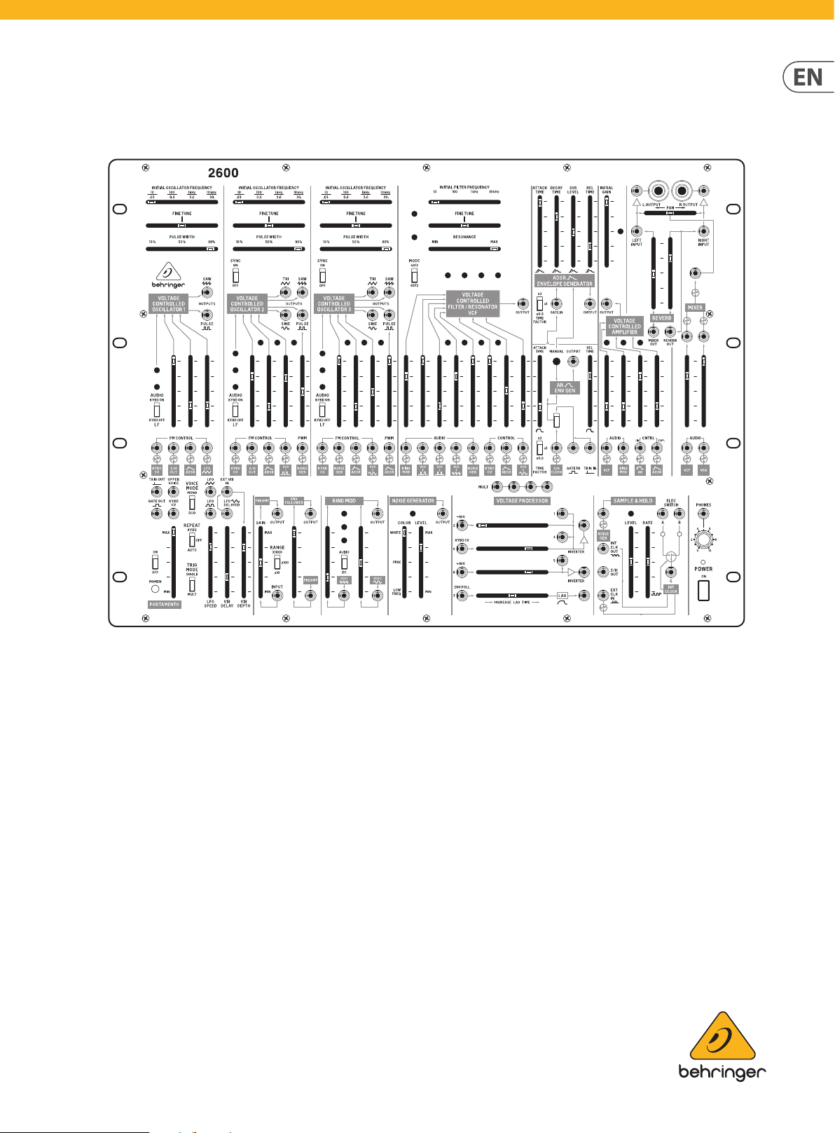
2600 Controls
Step 1: Controls
(EN)
Pre-Wired Connections
The panel silk-screening displays the various connections between modules that
have been pre-wired at the factory.
For example, in the VOLTAGE CONTROLLED FILTER/RESONATOR VCF section,
pre-wired connections from Voltage Controlled Oscillators 1, 2 and 3 into the VCF
block are indicated by the labeled boxes at the bottom of the section:
These labeled, pre-wired inputs correspond to sliders on the panel directly above
the label, which enables adjustment of the incoming signal strength.
The input jacks directly above each labeled box disconnects the pre-wired
connection whenever a 3.5 mm connector is placed into the jack,
as indicated by this graphic:
Voltage Controlled Oscillators (VCOs)
The Voltage Controlled Oscillators (VCOs) electronically generate repeating wave
signals, in a variety of waveforms that can then be shaped, combined and ltered
(1) INITIAL OSCILLATOR FREQUENCY – This slider chooses a VCO’s coarse
operating frequency in four ranges for audio (10 Hz, 100 Hz, 1 kHz or 10
kHz) or four sub-audio frequency ranges (.03 Hz, .3 Hz, 3.0 Hz or 30 Hz)
when the VCO operates as a Low Frequency Oscillator (LFO). To choose
between audio and LFO modes, use the AUDIO/LF sliding switch in the
lower left of each VCO.
(2) FINE TUNE – Use this slider to tune the frequency chosen by the INITIAL
OSCILLATOR FREQUENCY slider up or down as needed to nd the precise
frequency you need.
(3) PULSE WIDTH – Use this slider to set a default width for the waveform.
(4) SYNC ON/OFF – Use these sliding switches to lock VCO2 and/or VCO3 with
VCO1 so that the synced oscillators act as a single large oscillator that
follows the frequency of VCO1 to produce complex sounds.
(5) OUTPUTS – These output jacks allow you to send out either audio or
LFO signals from the VCOs via cables with 3.5 mm connectors. The type
of waveform is indicated by the silk-screening associated with the jacks
(sawtooth, pulse, sine, triangle, and so on, depending on the specic VCO
in use). The PULSE outputs can also be used to mix in signals from the
lower LFO section (VCO1), the NOISE GENERATOR section (VCO2), or the
ADSR ENVELOPE GENERATOR (VCO3) to produce a composite output signal.
(6) AUDIO/LF (KYBD ON/OFF) – This sliding switch chooses between audio
and low (LFO) frequencies for adjustment with the INITIAL OSCILLATOR
FREQUENCY, FINE TUNE and PULSE WIDTH sliders. When using the VCO as
a Low Frequency Oscillator, keyboard control is automatically disabled. In
the AUDIO position, keyboard control is enabled.
(7) FM CONTROL – Use these inputs to route in external control voltage
signals via cables with 3.5 mm connectors. Placing a connector into one of
these jacks disconnects the corresponding pre-wired connec tion indicated
directly below the jack.
(1)
(2)
(3)
(4)
(5)
(6)
(8) PWM – Use this input when you want to route in external control voltages
to control the pulse width in place of the PULSE WIDTH slider.
(7)
(8)
Page 6

10 2600 Quick Start Guide 11
(9)
(10)
(11)
(12)
(14)
(26)
(25)
(29)
(16)
(18)
(33)
(19)
(22)
(34)
(37)
(36)
(35)
2600 Controls
Voltage Controlled Filter (VCF)/Resonator Section
The VOLTAGE CONTROLLED FILTER (VCF)/RESONATOR uses a low-pass lter with
a variable cuto frequency (FC) and resonance (Q). The VCF can be controlled by
panel controls or by voltage control signals.
(13)
(15) CONTROL – Use these inputs for external control voltage signals via
cables with 3.5 mm connectors. Each of these inputs breaks the pre-wired
connection when a connector is inserted into the jack.
AR/ADSR Envelope Generator Section
These two envelope generators produce controllable, transient waveforms for
use mainly with the Voltage Controlled Filter (VCF) and the Voltage Controlled
Amplier (VCA).
The AR (Attack-Release) transient generator creates an adjustable transient
envelope every time the generator is activated by a gate or trigger voltage. The
voltage transient is shaped by the ATTACK TIME and RELEASE TIME sliders, and
the AR transient envelope is available at all pre-wired connections with this label:
(27)
(28)
(18) MANUAL – Press this button to manually produce a gate signal to trigger
both the AR and ADSR circuits.
(19) TIME FACTOR (x2/x1/x0.5) – Use this sliding switch to choose between
three basic time durations for the overall length of the envelope.
(20) ROUTING SWITCH – Use this sliding switch to choose between the S/H
CLOCK pre-wired connec tion, the GATE IN input or the TRIG IN input. The
signal chosen at this switch is also routed through to the ADSR generator.
(21) OUTPUT – Use this jack to send out an additional AR voltage envelope for
use where a pre-wired AR connection is not available.
(22) S&H CLOCK – This input allows you to substitute another external signal
for the Sample & Hold circuit’s output via a cable with a 3.5 mm connector.
(23) TRIG IN – This input jack allows you to route in a trigger voltage via a
cable with a 3.5 mm connector.
(24) GATE IN – This input jack allows you to route in a gate voltage into the AR
and ADSR circuits via a cable with a 3.5 mm connector.
The ADSR (Attack-Decay-Sustain-Release) transient generator works similarly to
the AR generator, but this circuit creates a more detailed voltage transient every
time the generator is triggered by a gate or trigger voltage. The voltage transient
is shaped by the ATTACK TIME, DECAY TIME, SUS LEVEL and REL TIME sliders, and
the ADSR voltage transient is available at all pre-wired connections with this
label:
Voltage Controlled Amplier Section
The Voltage Controlled Amplier (VCA) oers further tone-shaping possibilities
in parallel with the Voltage Controlled Filter (VCF) before both are blended in the
Mixer section. At maximum gain, the VCA passes signals through at unity gain. At
minimum gain, the VCA circuit will not pass a signal.
(46)
(41)
(45)
(44)
(40)
(39)
(43)
(42)
(15)
(9) INITIAL FILTER FREQUENCY – This slider sets the low-pass lter to four
coarse frequency points at 10 Hz, 100 Hz, 1 kHz and 10 kHz, which can then
be adjusted via the FINE TUNE slider.
(10) FINE TUNE – Use this slider to make further adjustments up or down from
the lter cuto point set by the INITIAL FILTER FREQUENCY slider.
(11) RESONANCE – Use this slider adjusts the lter’s Q setting. At the MAX
setting, the frequency curve below the lter cuto becomes a sharp and
the lter will ring in response to sharp pulses that pass through the lter.
(12) MODE (4012/4072) – This sliding switch chooses between two classic
lter circuits, the 4012 lter (the original lter design with a 16 Hz
maximum cuto frequency) and the 4072 lter (which had a lower
maximum cuto frequency at 11 Hz).
(13) OUTPUTS – This jack allows you to route out the VCF output for use in
other areas of the synthesizer via a cable with a 3.5 mm connector.
(14) AUDIO – These inputs allow you to route in audio signals via cables with
3.5 mm connectors. Each of these inputs breaks the pre-wired connection
when a connector is inserted into the jack.
(30)
(31)
(32)
(17)
(21)
(20)
(23)
(24)
(16) ATTACK TIME – This slider controls the shape of the note attack up to an
initial xed peak when a key is depressed or a gate/trigger control voltage
enters the circuit.
(17) RELEASE TIME – Use this slider to control the envelope shape following
the key release or release of the gate/trigger voltage.
(25) ATTACK TIME – This slider controls the shape of the note attack up to an
initial xed peak when a key is depressed a gate/trigger control voltage
enters the circuit.
(26) DECAY TIME – Use this slider to control how quickly the envelope drops
from the initial xed peak.
(27) SUS LEVEL – This slider controls the level at which the envelope holds
after the initial decay following the xed peak.
(28) REL TIME – Use this slider to control the envelope shape following the key
release or release of the gate/trigger control voltage.
(29) TIME FACTOR (x2/x1/x0.5) – Use this sliding switch to choose between
three basic time durations for the overall length of the envelope.
(30) OUTPUT – Use this jack to send out an additional ADSR voltage envelope
for use where a pre-wired ADSR connection is not available.
(31) GATE IN – Use this jack to route in a gate signal via a cable with a 3.5 mm
connec tor.
(32) MANUAL – Press this button to manually produce a gate signal to trigger
both the AR and ADSR circuits.
(33) ROUTING SWITCH – Use this sliding switch to choose bet ween the S/H
CLOCK pre-wired connec tion, the GATE IN input or the TRIG IN input. The
signal chosen at this switch is also routed through to the ADSR generator.
(38)
(34) INITIAL GAIN – This slider sets the overall gain for the VCA circuit.
(35) AUDIO – Use these inputs to route audio signals into the VCA and adjust
the signal gain using the slider immediately above the inputs. Inserting
the 3.5 mm connectors into the jacks will disable the pre-wired VCF and
RING MOD connections.
(36) CNTRL (LIN/EXPL) – These inputs can accept control voltage signals
via cables with 3.5 mm connec tors. The left input has a linear response,
while the right input features an exponential response. Inserting 3.5
mm connectors into these jacks will disable the pre-wired AR and ADSR
connections.
(37) OUTPUT – Use this output to route the nal VCA signal out for use where a
pre-wired VCA signal is not available.
Page 7

12 2600 Quick Start Guide 13
(47)
(48)
(56)
(55)
(54)
(57)
(58)
(61)
(67)
(65)
(64)
(66)
2600 Controls
Mixer/Reverb Section
The Mixer section accepts two inputs that are balanced via the t wo sliders and
then summed into a single signal. After being summed, the combined signal can
then be panned before going to the stereo outputs. The Mixer section is prewired with inputs from the VCF and VCA.
NOTE: 2600 uses a digital reverb, while BLUE MARVIN features a real,
on-board spring reverb.
(38) AUDIO – Use these two inputs to route audio signals into the Mixer via
cables with 3.5 mm connectors. Inserting 3.5 mm connectors into these
jacks will disable the pre-wired VCF and VCA connections.
(39) POST-ATTENUATOR OUTPUTS – These two outputs allow you to send
signals out immediately following the attenuator sliders, which means the
sliders can be used to attenuate audio or control voltage signals for use
elsewhere.
(40) POST-MIXER OUTPUT – This input breaks the signal connection from the
Mixer to the PAN slider when a 3.5 mm connector is inser ted. Use this input
to route in an outside signal for use by the PAN slider. The Mixer output still
goes to the Reverb circuit via a pre-wired connection.
(41) PAN – Use this slider to place the summed Mixer signal where desired in
the left-right stereo eld before nal output.
(42) MIXER OUT – This output is an additional Mixer output that taps the pre-
wired Mixer connection which feeds into the Reverb circuit.
(43) REVERB OUT – This output taps the right Reverb signal for use elsewhere.
Keyboard/Portamento Section
The Keyboard section determines how the built-in Low Frequency Oscillator (LFO)
unit works with an external keyboard.
The keyboard control voltage is available as a pre-wired connection wherever
you see this label:
(49)
(51)
(50)
(52)
(53)
(54) ON/OFF – This switch turns the Portamento function on or o.
(55) MOMEN – Pressing this button temporarily activates the Portamento
function for as long as the button is held down.
(56) MAX/MIN – This slider controls the strength of the Portamento eect.
The MAX setting provides the most gradual and smooth eect.
Low Frequency Oscillator (LFO) Section
The unit includes a purpose-built Low Frequency Oscillator (LFO) primarily meant
to function with a keyboard. The LFO has a pre-wired connection to VCO1, as
indicated by this label:
(59)
(60)
Envelope Follower Section
The Envelope Follower generates an output voltage based on an input signal,
depending on the average amplitude of the input signal. The generated control
voltage’s characteristics can be adjusted to create various eects when the
output is routed to the VCF, VCA or the VCOs.
The input signal can be adjusted via the Preamp, which feeds into the Envelope
Follower via a pre-wired connection.
The Envelope Follower’s output does not have a pre-wired connec tion to other
sections of the synthesizer.
(70)
(69)
(68)
(44) LEFT INPUT – Use this input to add an additional signal to the Reverb
circuit’s left output. The additional signal will be summed with the left
Reverb output and panned hard left in the stereo eld.
(45) RIGHT INPUT – Use this input to add an additional signal to the Reverb
circuit’s right output. The additional signal will be summed with the right
Reverb output and panned hard right in the stereo eld.
(46) L OUTPUT/R OUTPUT – The nal stereo left-right outputs each have
matching parallel pairs of ¼” and 3.5 mm connections. The ¼” outputs
can be used to send the nal mix to external ampliers, speakers or other
processing equipment. The parallel 3.5 mm jacks can be used to send the
left and right outputs to other synth circuits for further processing.
(47) TRIG OUT – Use this output to send out a trigger control voltage for use
elsewhere via a cable with a 3.5 mm connector.
(48) GATE OUT – This output can be used to send out a gate control voltage via
a cable with a 3.5 mm connector.
(49) UPPER VOICE – This output sends out a control voltage based on the
highest note being played on the keyboard while in DUO voice mode.
(50) KYBD CV – This output sends out the complete keyboard control voltage
signal for use elsewhere.
(51) VOICE MODE(MONO/DUO) – Use this sliding switch to determine
whether the keyboard plays one voice at a time (MONO) or two voices
simultaneously (DUO).
(52) REPEAT (KYBD/OFF/AUTO) – Use this sliding switch to control how
the keyboard sends trigger signals. When the switch is set to the KYBD
position, the keyboard will send out repeating trigger pulses as long a key
is held down. In the AUTO setting, the keyboard will send out a stream of
trigger pulses based on the synthesizer’s LFO setting. When the switch
is in the center OFF position, the keyboard will generate only one trigger
pulse per key press (i.e., the keyboard will revert to “normal” keyboard
functionality).
(53) TRIG MODE (SINGLE/MULT) – When this switch is set to SINGLE, the
keyboard will only generate a trigger pulse when a key is played while no
other keys are being played. In MULT mode, the keyboard will generate
a trigger pulse every time any key is pressed down, even if previously
pressed keys are held down.
(63)
(62)
(57) LFO (SAW) – This output allows you to route a sawtooth LFO signal out for
use elsewhere via a cable with 3.5 mm connectors.
(58) LFO (SQUARE) – This output allows you to route a square wave LFO signal
out for use elsewhere.
(59) EXT VIB IN – This input allows you to route in an external LFO signal for
blending with the delayed LFO sine wave.
(60) LFO (SINE) DELAYED – This output can be used to send out a copy of the
LFO’s pre-wired sine wave output for use elsewhere. This output signal is
delayed at a rate controlled by the VIB DELAY slider.
(61) LFO SPEED – Controls the base speed of the LFO oscillation.
(62) VIB DELAY – This slider controls the amount of delay applied to the LFO
sine wave.
(63) VIB DEPTH – This slider controls the intensity of the vibrato eect created
by the delayed sine wave LFO signal.
(64) PREAMP INPUT – Use this input to route an external signal into the
Preamp via a cable with a 3.5 mm connector.
(65) RANGE (X1000/ X100/ X10) – Use this sliding switch to determine the
base amount of amplication applied to the input signal and then adjusted
via the GAIN slider.
(66) GAIN – This slider determines how strongly the input signal is amplied.
(67) PREAMP OUTPUT – This output sends out a copy of the Preamp signal for
use elsewhere in the synth.
(68) PREAMP INPUT – This input allows you to bypass the Preamp and route
an external signal directly into the Envelope Follower. Alternately, the
input signal can be blended with the signal coming into the Envelope
Follower via the pre-wired connection.
(69) SENSITIVITY – This slider controls the sensitivity of the Envelope Follower
circuit.
(70) OUTPUT (ENVELOPE FOLLOWER) – Use this output to route the nal
Envelope Follower signal out for use elsewhere in the synthesizer via a
cable with a 3.5 mm connector.
The Portamento function allows one pitch to change gradually to a second pitch
a predetermined rate.
Page 8

14 2600 Quick Start Guide 15
(73)
(71)
(75)
(79)
(80)
(81)
(82) (83)
(84)
(85)
(86)
(87)
2600 Controls
Ring Modulator Section
The Ring Modulator is a voltage multiplier that combines two input signals to
produce a variety of exotic timbres. By default, the two pre-wired signals come
into the circuit from VCO1 (sawtooth) and VCO2 (sine).
The Ring Modulator output is available as a pre-wired connection wherever you
see this label:
(74)
Noise Generator Section
The Noise Generator produces a noise signal that can be adjusted between white,
pink and low frequency types of noise, each of which has distinct characteristics
and can then be processed in other sections of the synth to design sounds.
The Noise Generator output is available as a pre-wired connection wherever you
see this label:
(77)
(76)
Voltage Processor Section
The Voltage Processor oers three dierent processors for both audio and control
voltage signals. Two of the processors are for mixing and inverting signals, while
the third processor applies a variable lag to the signal.
The Voltage Processor’s output is not available elsewhere in the synth as a prewired signal, and so requires cables.
(79)
(76)
(82) ENV FOLL – This input can accept both control voltages and audio signals
but is optimized to process the Envelope Follower output signal.
(83) LAG – This jack sends out the nal signal from the Lag Processor.
Sample & Hold/Electronic Switch Section
Sample & Hold
The Sample & Hold circuit takes an input signal and converts that signal into
a stepped output by taking samples of the input signal at set intervals. For
example, a smooth sine wave input will appear at the output as a squared-o,
approximate version of the original smooth waveform. This stepped waveform
can then be sent other areas of the synthesizer to create exotic sounds and
textures.
This Sample & Hold circuit has an internal clock generator and a pre-wired
connection from the Noise Generator circuit.
The Sample & Hold circuit’s output is available as a pre-wired connection
wherever you see this label:
(72)
(71) VCO 1 – This input jack allows you to route in an external signal for
blending with the pre-wired VCO1 sawtooth signal. The overall gain for
this combined signal is adjusted by the adjacent slider.
(72) VCO 2 – This input jack allows you to route in an external signal for
blending with the pre-wired VCO2 sine wave signal. The overall gain for
this combined signal is adjusted by the adjacent slider.
(73) AUDIO/DC – Use this switch to optimize the VCO1 signal path for audio
(AUDIO) or control voltage (DC) signals.
(74) RING MOD OUTPUT – This jack can be used to send out the nal, summed
Ring Modulator for use elsewhere where a pre-wired connection is not
available.
(75) COLOR – Use this slider to move between white noise (WHITE), pink noise
(PINK) and low frequency noise (LOW FREQ).
(76) LEVEL – This slider controls the overall attenuation of the noise signal
prior to output.
(77) NOISE GENERATOR OUTPUT – Use this output to send the nal noise
signal out for use in the synth where a pre-wired connection is not
available.
(78) MULT – These linked parallel connections can be used as a patch bay to
duplicate and combine signals. The MULT connections can function as both
inputs and outputs.
Inverter 1
Inverter 1 accepts four dierent inputs, which are summed and then inverted.
For example, a +10 V input to INPUT 1 will leave Inverter 1 with a value of -10 V,
while an audio signal will be output with the phase reversed 180°.
(79) -10 V – This input attenuates the input signal by 10 V.
(80) KYBD CV – This input is optimized for control voltage signal from a
keyboard.
Inverter 2
Inverter 2 can accept two signals, which are then summed and inverted for
output.
(81) +10 V – This inputs boosts the input signal by +10 V.
Lag Processor
The Lag Processor responds to sudden changes in input voltage and slows down
those changes by an amount controlled by the slider. For audio signals, the Lag
Processor will cut o treble frequencies by increasing amounts, similar to a lowpass lter.
(90)
(89)
(88)
(84) NOISE GENERATOR – This input jack interrupts the Noise Generator input
signal when a 3.5 mm connector is inserted into the jack. Use this jack to
substitute another signal for the Noise Generator signal.
(85) INT CLOCK OUT – Use this jack to export the internally generated clock
signal for use in other parts of the synthesizer.
(86) S/H OUT – Use this jack to send out the Sample & Hold circuit’s nal signal
for use elsewhere in the synthesizer where a pre-wired connec tion is not
available.
Page 9

16 2600 Quick Start Guide 17
2600 Controls
(87) EXT CLK IN – This jack can be used to import an external clock signal
to run the Sample & Hold circuit. Placing a 3.5 mm connector into this
jack will disable the internal clock generator. Any square or pulse wave
generated in other areas of the synthesizer, as well gate or trigger signals
from the keyboard can be routed into this jack and used as a clock signal.
(88) LEVEL – This slider attenuates the input signal before it goes into the
Sample & Hold circuit.
(89) R ATE – This slider controls the speed of the internal clock generator
and therefore controls how often the Sample & Hold circuit takes a
measurement of the input signal. When the internal clock signal is
interrupted by use of the EXT CLK IN input, the RATE slider will not
function.
Electronic Switch
The Electronic Switch connections are bidirectional. This circuit can alternate a
single input from C between the A and B outputs, or the circuit can route two
signals into the A and B jacks and then alternate the C output between the A and
B input signals. The rate of back-and-forth switching in both of these scenarios
is controlled by the Sample & Hold circuit’s internal clock (or an external clock
source routed in through the EXT CLK IN jack.
(90) ELEC SWITCH A/B/C – These jacks route signals in and out over cables
with 3.5 mm connectors.
Phones/Power
(91) PHONES – Use this jack to connect headphones that use 1/8” plugs and
control the output level with the knob immediately below the jack. The
headphone jack is connected to the Mixer output.
(92) POWER – Press this switch to turn the synthesizer on or o. Make sure all
the connections are made before turning on the unit.
Back Panel
(93) (94) (95) (96) (97) (98) (99) (100)
(96) MIDI CHANNEL SWITCHES – These 4 switches allow you to set the MIDI
Channel number from 1 to 16 (see the table printed in this document or
refer to the silk-screened switch matrix printed on the back panel).
1 2 3 4
5 6 7 8
9 10 11 12
13 14 15 16
(97) MIDI IN – This port receives MIDI data from an external source over
a 5-pin DIN connector. This external source will commonly be a MIDI
keyboard, an external hardware sequencer, a computer equipped with a
MIDI interface, and so on.
(98) MIDI THRU – This port uses a 5-pin DIN jack is used to pass through MIDI
data received at the MIDI IN jack. This MIDI data will commonly be sent
to another synthesizer or to a drum machine assigned to a dierent MIDI
Channel.
(99) USB PORT – This jack allows connection to a computer over a USB type B
connection. This synthesizer will show up as a class-compliant USB MIDI
device, capable of supporting MIDI in and out.
(100) DC INPUT – Connect the supplied 12V DC power adapter here. The power
adapter can be plugged into an AC outlet capable of supplying from 100V
to 240V at 50 Hz/60 Hz. Use only the power adapter supplied.
Specications
Inputs
VCO 1 / 2 / 3
Frequency modulation (FM) control 11 x 3.5 mm TS jacks, CV range: -10 V to +10 V
Pulse width modulation (PWM) 2 x 3.5 mm TS jack, CV range: -5 V to +5 V, 1 V/10%
VCF
Audio 5 x 3.5 mm TS jacks, 50 k unbalanced
Control 3 x 3.5 mm TS jacks, C V range: -10 V to +10 V
ADSR / AR envelope generator
S&H clock 1 x 3.5 mm TS jack, threshold: > 6 V
Gate in 1 x 3.5 mm TS jack, threshold: +4 V
Trig in 1 x 3.5 mm TS jack, threshold: +5 V
VCA
Audio 2 x 3.5 mm TS jacks, 50 k unbalanced
Control (linear) 1 x 3.5 mm TS jack, CV range: -10 V to +10 V
Control (exponential) 1 x 3.5 mm TS jack, CV range: -10 V to +10 V
Mixer / Reverb
Audio 2 x 3.5 mm TS jacks, 50 k unbalanced
Left / right inputs 2 x 3.5 mm TS jacks, 50 k unbalanced
LFO
Ext vib in 1 x 3.5 mm TS jack, 50 k unbalanced
Envelope Follower
Input 1 x 3.5 mm TS jack, 100 k unbalanced
Preamp input 1 x 3.5 mm TS jack, 100 k unbalanced
Ring Modulator
VCO 1 input 1 x 3.5 mm TS jack, 100 k unbalanced
VCO 2 input 1 x 3.5 mm TS jack, 100 k unbalanced
Voltage Processor
-10 V input 1 x 3.5 mm TS jack, max. input level: +10 V
Inputs 1 / 3 / 5 3 x 3.5 mm TS jacks, ma x. input level: +10 V
Keyboard CV input 1 x 3.5 mm TS jack, max. input level: +10 V
+10 V input 1 x 3.5 mm TS jack, max. input level: +10 V
Env follower input 1 x 3.5 mm TS jack, max. input level: +10 V
Sample & Hold
Noise gen input 1 x 3.5 mm TS jack, 50 k unbalanced
Ext clock in 1 x 3.5 mm TS jack, threshold: > 3 V
Back Panel
Interval latch 1 x ¼" TRS
Portamento footswitch 1 x ¼" TRS
(93) LED – Use this rotary knob to control the brightness of the LEDs on the
front panel.
(94) INTERVAL LATCH – Use this ¼” jack with an external footswitch to
temporarily turn on the interval function. When the VOICE MODE switch
is in the DUO position, playing two notes and depressing the footswitch
maintains the two-note interval while you play further single notes.
(95) PORTAMENTO FOOTSWITCH – Use this ¼” jack with an external
footswitch to turn the Portamento function on or o.
Page 10

18 2600 Quick Start Guide 19
Specications
Outputs
VCO 1 / 2 / 3
Outputs (saw) 3 x 3.5 mm TS jacks, 1 k unbalanced
Outputs (pulse) 3 x 3.5 mm TS jacks, 800 unbalanced
Outputs (tri) 2 x 3.5 mm TS jacks, 1 k unbalanced (VCO 2 / 3 only)
Outputs (sine) 2 x 3.5 mm TS jacks, 1 k unbalance d (VCO 2 / 3 only)
VCF
Outputs 1 x 3.5 mm TS jack, 1 k unbalanced
ADSR / AR Envelope Generator
Output 2 x 3.5 mm TS jacks, CV range: 0 V to +10 V
VCA
Output 1 x 3.5 mm TS jack, 1 k unbalanced
Mixer / reverb
Post-attenuator outputs 2 x 3.5 mm TS jacks, 1 k unbalanced
Post-mixer output 1 x 3.5 mm TS jack, 1 k unbalanced
L / R outputs
LFO
LFO (triangle) 1 x 3.5 mm TS jack, 1 k unb alanced
LFO (square) 1 x 3.5 mm TS jack, 1.8 k unbalanced
LFO delayed (sine) 1 x 3.5 mm TS jack, 1 k unbalanced
Envelope follower
Output (preamp x1000 ) 1 x 3.5 mm TS jack, max. output gain: +6 0 dBu
Output (preamp x100 ) 1 x 3.5 mm TS jack, max. output gain: +40 dBu
Output (preamp x10 ) 1 x 3.5 mm TS jack, max. output gain: +20 dBu
Output (env follower) 1 x 3.5 mm TS jack, max. output level: +14 V
Ring modulator
Output 1 x 3.5 mm TS jack, output level: -10 V to +10 V
Noise generator
Output 1 x 3.5 mm TS jack, output level: -10 V to +10 V
Voltage processor
Inverter 1 out put 1 x 3.5 mm TS jack, outp ut level: -10 V to +10 V
Inverter 2 out put 1 x 3.5 mm TS jack, outp ut level: -10 V to +10 V
Lag output 1 x 3.5 mm TS jack, output level: -10 V to +10 V
Sample & hold
Internal clock out 1 x 3.5 mm TS jack, max. out put level: +10 V
S/H out 1 x 3.5 mm TS jack, max. output level: +14 V
Portamento / keyboard
Tri g out 1 x 3.5 mm TS jack, output level: +14 V
Upper voice 1 x 3.5 mm TS jack, max. output level: +10 V
Gate out 1 x 3.5 mm TS jack, output level: +10 V
Keyboard CV output 1 x 3.5 mm TS jack, max. output level: +7 V
Phones
Typ e 1 x ⁄" TRS jack, s tereo
Max. outpu t level 5 dBu
Output impedance 8
Dual Inputs / Outputs
Voltage Processor
Mult inputs / outputs 4 x 3.5 mm TS jacks, all direct connection.
Sample & Hold
Elec switch A / B / C 3 x 3.5 mm TS jack s, A / C on or B / C on
MIDI in / thru 2 x 5-pin DIN, 16 channels
USB (MIDI) Typ e B
2 x ¼" TS, 500 unbalanced
2 x 3.5 mm TS jacks, 50 0 unbalanced
Controls
VCO 1 / 2 / 3
Initial oscillator frequency: 10 (0.03) Hz / 100 (0.3) Hz / 1 (3.0 Hz) kHz /
10 (30 Hz) kHz, select able
Fine tune
Pulse width: 10% to 90 %
Audio / LF (Kybd on / o )
Sliders
Switches
VCF / Resonator
Sliders
Switches Mode: 4 012 / 4072, selectable
AR / ADSR envelope generator
Sliders
Switches Time f actor: x0.5 / x1 / x2, selec table
VCA
Sliders
Mixer / reverb
Sliders
LFO
Sliders
Envelope follower
Sliders
Switches Gain range: x10 (20 dB) / x100 (40 dB) / x1000 (60 dB) , selectable
Ring modulator
Sliders
Noise generator
Sliders Color: low freq / pink / white, adjustable Level
Sync on / o (VCO 2 / 3 only)
S / H slider (VCO 1 / 2 only)
ADSR
LFO (VCO 1 only)
VCO 1 (pulse, VCO 2 only)
VCO 2 (sine, VCO 3 only)
Noise generator (VCO 2 / 3 only)
Audio / LF (kyb d on / o)
Sync on / o (VCO 1 / 2 only)
Initial lter frequency
Fine tune
Resonance
Ring modulator
VCO 1 (pulse)
VCO 2 (pulse)
VCO 3 (saw)
Noise generator
Keyboard CV
ADSR
VCO 2 (sine)
"At tack time
Decay time
Sus level
Release time
Time fac tor
Manual"
Initial gain
VCF
Ring modulator
AR
ADSR
VCF
VCA
Reverb L / R
Pan
LFO speed
Vib delay
Vib depth
Input gain
Preamp gain
VCO 1 (saw)
VCO 2 (sine)
Page 11

20 2600 Quick Start Guide 21
Specications
Controls
Voltage processor
-10 V gain
Sliders
Sample & hold
Sliders
Portamento
Sliders Portamento: min to max
Switches
Keyboard
Switches
Phones level 1 x rotary knob: 0 to 10
Power 1 x rocker s witch
Back panel
LED 1 x rotary k nob: min to max
MIDI channel switches 4 x DIP switches
Synthesizer Architecture
Number of voices Multiphonic
Typ e Analog
VCO 3 (0.03 Hz to 40 kHz in 4 overlapping ranges)
LFO 1 (0.25 Hz to 25 Hz)
VCF 1 x 4-pole low pass (24 dB/oct. slop e)
VCA 1
Envelopes AR, ADSR
Eects Digital spring reverb
USB
Typ e Class compliant USB 2.0, type B
Supported operating systems
Power
External power adapter 12 V DC, 2000 mA
Power consumption Max. 15 W
Physical
Standard operating temperature range 5° C to 40° C (41° F to 104° F)
Dimensions 482 x 356 x 108 mm (19 x 14 x 4.3")
Rack units 95 HP
Weight 5.1 kg (11.22 lbs)
Keyboard CV gain
+10 V gain
Increase lag time
Level
Rate
On / o
Momen
Voice mode: mono / duo, selectable
Repeat: keybo ard /o / auto, selectable
Trig mode: single / multi, select able
Windows 7 or higher
Mac OS X 10.6.8 or higher
Page 12

22 2600 Quick Start Guide 23
FEDERAL COMMUNICATIONS
COMMISSION COMPLIANCE
INFORMATION
2600
Responsible Party Name: Music Tribe Commercial NV Inc.
Address: 901 Grier Drive
Las Vegas, NV 89118
USA
Phone Number: +1 747 237 5033
2600
This equipment has been tested and found to comply with the limits for a Class B
digital device, pur suant to part 15 of the FCC Rules. These limits are designed
to provide reasonable protection against harmful interference in a residential
installation. This equipment generates, uses and can radiate radio frequency
energy and, if not installed and used in accordance with the instruc tions, may cause
harmful interference to radio communications. However, there is no guarantee that
interference will not occur in a particular installation. If this equipment does cause
harmful interference to radio or television reception, which can be determined
by turning the equipment o and on, the user is encouraged to try to correct the
interference by one or more of the following measures:
• • Reorient or relocate the receiving antenna.
• • Increase the separation between the equipment and receiver.
• • Connect the equipment into an outlet on a circuit dierent from that to which the
receiver is connected.
• • Consult the dealer or an experienced radio/TV technician for help.
This device complies with Part 15 of the FCC rules. Operation is subject to the
following two conditions:
(1) this device may not cause harmful interference, and
(2) this device must accept any inter ference received, including inter ference that may
cause undesired operation.
Important information:
Changes or modications to the equipment not expressly approved by Music Tribe
can void the user’s authority to use the equipment.
Page 13

We Hear You
 Loading...