

Page 1
C9900-U3x0
Uninterruptible Power Supply (UPS)
for industrial PC with 24 V
supply voltage
DC
Version: 1.5
Date: 2011-09-29
Page 2

Page 3

Table of Contents
Table of Contents
1.
Foreword 1
Description of safety symbols 2
2.
The C2000BAT UPS control board 3
3.
Power pack for Beckhoff IPC with UPS 4
C9900-U310, C9900-U320 4
C9900-U300 6
Connecting the Battery 8
Maximum length of the feeder cable 9
Operating conditions 9
4.
Installing the UPS 10
Configuration under TwinCAT 10
Configuration of the UPS with CP9090-S100 13
5.
Technical data 14
Layout of the CP-Link board CP9030 14
Layout of the UPS interface card C1230S 15
The charging system 15
6.
Appendix 17
Beckhoff Support & Service 17
C9900-U3x0
Page 4

Foreword
Foreword
Notes on the Documentation
This description is only intended for the use of trained specialists in control
and automation engineering who are familiar with the applicable national
standards. It is essential that the following notes and explanations are
followed when installing and commissioning these components.
The responsible staff must ensure that the application or use of the
products described satisfy all the requirements for safety, including all the
relevant laws, regulations, guidelines and standards.
Liability Conditions
The documentation has been prepared with care. The products described
are, however, constantly under development. For that reason the
documentation is not in every case checked for consistency with
performance data, standards or other characteristics. In the event that it
contains technical or editorial errors, we retain the right to make alterations
at any time and without warning. No claims for the modification of products
that have already been supplied may be made on the basis of the data,
diagrams and descriptions in this documentation.
Trademarks
Beckhoff®, TwinCAT®, EtherCAT®, Safety over EtherCAT®, TwinSAFE®
and XFC
Automation GmbH.
Other designations used in this publication may be trademarks whose use
by third parties for their own purposes could violate the rights of the
owners.
Patent Pending
The EtherCAT Technology is covered, including but not limited to the
following patent applications and patents:
EP1590927, EP1789857, DE102004044764, DE102007017835
with corresponding applications or registrations in various other countries.
The TwinCAT Technology is covered, including but not limited to the
following patent applications and patents:
EP0851348, US6167425 with corresponding applications or registrations in
various other countries.
Copyright
© Beckhoff Automation GmbH.
The reproduction, distribution and utilization of this document as well as the
communication of its contents to others without express authorization are
prohibited. Offenders will be held liable for the payment of damages. All
rights reserved in the event of the grant of a patent, utility model or design.
State at Delivery
All the components are supplied in particular hardware and software
configurations appropriate for the application. Modifications to hardware or
software configurations other than those described in the documentation
are not permitted, and nullify the liability of Beckhoff Automation GmbH.
Delivery conditions
In addition, the general delivery conditions of the company Beckhoff
Automation GmbH apply.
®
are registered trademarks of and licensed by Beckhoff
C9900-U3x0 1
Page 5
Foreword
Description of safety symbols
The following safety symbols are used in this operating manual. They are
intended to alert the reader to the associated safety instructions.
Acute risk of injury!!
DANGER
WARNING
CAUTION
Attention
Note
If you do not adhere the safety advise adjoining this symbol, there is
immediate danger to life and health of individuals!
Risk of injury!
If you do not adhere the safety advise adjoining this symbol, there is
danger to life and health of individuals!
Hazard to individuals!
If you do not adhere the safety advise adjoining this symbol, there is
obvious hazard to individuals!
Hazard to devices and environment
If you do not adhere the notice adjoining this symbol, there is obvious
hazard to materials and environment.
Note or pointer
This symbol indicates information that contributes to better understanding.
2 C9900-U3x0
Page 6
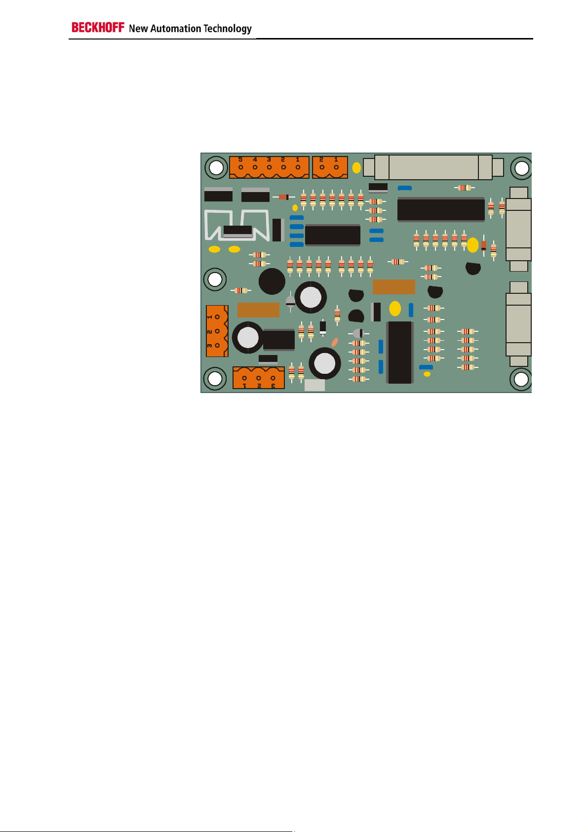
The C2000BAT UPS control board
The C2000BAT UPS control board
Uninterruptible power
supply
Not all connections are
used in the application with
the C1230S
An industry PC with a 24 V power supply can optionally be fitted with an
uninterruptible power supply, which maintains correct operation of the
device for about 15 minutes by means of a NiCad battery, after failure of
the main power supply. The control is performed by the C2000BAT UPS
control board.
Battery/Pwr. sup.
Fuse
Mains power
supply board
1A
LCdisplay
CP9030/C1230S
1
not
11
not
used
used
Switch for
LCD illumination
Battery reverse connection
protection
Fuse inside the battery
Switch for the LCD
background illumination
(only older devices, e.g.
C20xx, C32xx)
The NiCad battery (18 V / 0.65 Ah / 1,8 Ah / 2,5 Ah) supplies the device for
The UPS control board is fitted with a simple form of protection against
reverse battery connection. If the battery is accidentally connected with the
wrong polarity, high current flows for a short period, and this blows the fuse
(3,15 A) on the C2000BAT board. The location of the fuse on the board
can be seen in figure 1. There is also a fuse (8 A) inside the battery, to
provide short circuit.
The UPS control board allows the LCD back light to be switched on and off
by means of a switch on the side of the housing, or by software through the
PIO chips on the C1230S. Switching the LCD back light off can save
current under battery operation. If the software has switched the back light
off when under battery power, it can be switched on again using the switch.
up to 15 minutes, depending on how fully charged the battery is and on the
hardware installed in the IPC, giving the software time to save all its data.
This time may be only app. 4 minutes with devices of higher energy
consumption.
BECKHOFF C2000BAT
C9900-U3x0 3
Page 7

Power pack for Beckhoff IPC with UPS
Power pack for Beckhoff IPC with UPS
There are three types for the uninterruptible power system (UPS):
• C9900-U300: Power pack 18 V / 0,6 Ah
• C9900-U310: Power pack 18 V / 1,8 Ah
• C9900-U320: Power pack 18 V / 2,5 Ah
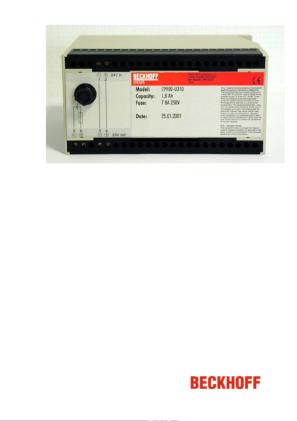
C9900-U310, C9900-U320
Front view U310, U320
Side view U310, U320
4 C9900-U3x0
Page 8

Power pack for Beckhoff IPC with UPS
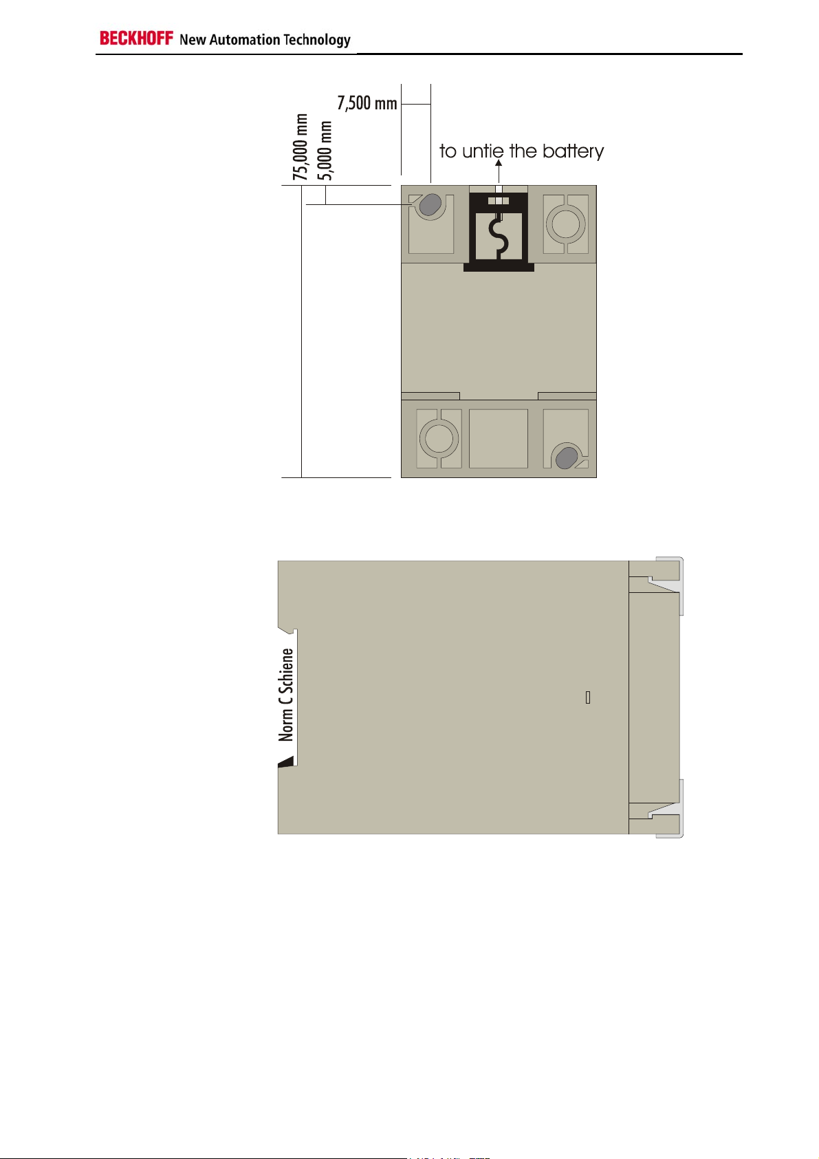
Rear view U310, U320
Side view U310, U320
(top-hat rail mounting)
C9900-U3x0 5
Page 9

Power pack for Beckhoff IPC with UPS
C9900-U300
Front view U300
Side view U300
6 C9900-U3x0
Page 10
Power pack for Beckhoff IPC with UPS
Rear view U300
Side view U300
(top-hat rail mounting)
C9900-U3x0 7
Page 11

Power pack for Beckhoff IPC with UPS
Connecting the Battery
Normally, the battery is mounted in an control cabinet, near to the industrial
PC. The fixing on DIN rail enables a simple and quick mounting and
demounting.
The connection of the 24 VDC to the battery should be made via a cable
with 2 x 1.5mm². The transmission of the 24VDC and the UPS-voltage is
made via a cable with 4 x 1.5mm² (see .figure). At the end of the cable, the
version of the connecting plug is connected, according to the PC series.
8 C9900-U3x0
Page 12

Power pack for Beckhoff IPC with UPS
Maximum length of the feeder cable
Maximum cable length The maximum length of the UPS feeder cable must not be longer than
• 4 meters at a conductor cross section of 1.5 mm²!
• 8 meters at a conductor cross section of 2.5 mm²!
Operating conditions
Ambient temperature:
C9900-U300 0 to 40 °C
C9900-U310 0 to 40 °C
C9900-U320 0 to 55 °C
Atmospheric humidity:
C9900-U3x0 Maximum 95 %, non-condensing
Supply voltage:
C9900-U3x0 from C2000BAT (charge controller)
CP9030 5 V direct voltage ± 5%
12 V direct voltage ±5 %
C1230S: 5 V direct voltage ± 5%
12 V direct voltage ±5 %
C9900-U3x0 9
Page 13

Installing the UPS
Installing the UPS
Two different circuit boards can be used to drive the UPS: the CP-Link card
CP9030, or the interface card C1230S. See appendix technical data for
detailed information.
The UPS can be configured under Windows NT/2000/XP with TwinCAT CP
or under Windows 95/98/NT with the ActiveX component CP9090-S100.
Configuration under TwinCAT
Configure the CP link card CP9030
Start the TwinCAT System Manager and click with the right mouse button
onto I/O devices. Choose append device.
Choose the I/O device Beckhoff Panel-Link (CP9030)
10 C9900-U3x0
Page 14

Installing the UPS
Make sure, that the address of the driving CP link card is correct. Click
onto the tab UPS to complete the configuration of this device.
In order to activate the UPS under TwinCAT, the check box Use UPS must
be selected. The wait time dictates the period of time before the PC will
shut down after failure of the external supply voltage.
System Manager:
tab UPS CP9030
After the settings are made, make sure,
• to create the relations,
• check the configuration and
• safe the settings into the registry
These points can be found in the action menu.
C9900-U3x0 11
Page 15

Installing the UPS
Configure the interface card C1230S
Start the TwinCAT System Manager and click with the right mouse button
onto I/O devices. Choose append device.
Choose the I/O device Beckhoff IPC (C1230-S)
In order to activate the UPS under TwinCAT, the check box Use UPS must
be selected. The wait time dictates the period of time before the PC will
shut down after failure of the external supply voltage.
12 C9900-U3x0
Page 16

Installing the UPS
System Manager:
Tab UPS C1230S
After the settings are made, make sure,
• to create the relations,
• check the configuration and
• safe the settings into the registry
These points can be found in the action menu.
Configuration of the UPS with CP9090-S100
Information about setting the UPS by using the ActiveX component
CP9090-S100 may be taken from the documentation CP9090-S100.PDF. It
is to be found in the internet on our home page http://www.beckhoff.com
under Download/TwinCAT/CP9090.
C9900-U3x0 13
Page 17

Technical data
O
P234O
P12345678
T30
4
W50
0SW40
0
T50
T30
5ST30
2ST30
T20
2
2IC
2
C
5
nkACP
n
k
o
nB5
Technical data
The CP-Link board CP9030 and the interface card C1230S, allow a 24 V
UPS (uninterruptible power supply) to be controlled. The connection of the
UPS control board C2000BAT to the
• CP9030 is made by the ribbon cable ST501 (connector name)
• C1230S is made by the ribbon cable ST703 (connector name)
Layout of the CP-Link board CP9030
ST3 06
1
S
S
NDI
S
NDI
J300
ST20
S
JU201
JU202
JU203
01
LED02LED03LED04LED
LED
01
CP9030_3
05
LED 06
LED 07
CP-Li
ST2 03
I
00
ST4 04
Ver si
01.11.1 998
S
1
12
910
Bayview
Vers ion 1. 1
-Li
B
JU401
JU402
1
ST3 03
ST501 pin assignment (24 V, UPS control)
PIN Signal PIN Signal
1
2
3
4
5
GND
PCL0
PCL1
PCH0
PCH1
10
6
7
8
9
PA0
PA1
PA2
PA3
PA4
Link label CP9030 → UPS
CP9030 PIN C2000BAT PIN CP9030 PIN C2000BAT PIN
GND
UPS-PLC1
UPS-PCH1
UPS-PA1
UPS-PA3
1
GND
3
Not used
5
Not used
7
Ext.supply OK
9
Not used
26
23
21
19
11
UPS-PCL0
UPS-PCH0
UPS-PA0
UPS-PA2
UPS-PA4
2
UPS-activ-passive
4
Not used
6
Load. controller
8
Power pack volt.
10
Not used
24
22
20
12
10
14 C9900-U3x0
Page 18

Technical data
Memory allocation in the DPRAM
The mentioned address means the offset from the base address of the CP
link card (e.g. CP link card on &HCC00:0000, loading controller on
&HCC00:03ED). Take care about the configuration of the PC, to avoid
overlapping with other PC cards.
0x03EC UPS control
Loading controller 0x03ED UPS status
Waiting Loaded No power pack Loading
active
Power
pack volt.
Ext.
supply OK
Layout of the UPS interface card C1230S
Syst e m- B us
1 ST703
USV
1 ST701
Fr on t t ab l e au
1 ST702
ST1 00 0
The charging system
An integrated charger ensures that the battery is always kept fully charged.
The charging current is 1/3 of the full capacity, i.e. about 200-800 mA. The
charging procedure therefore takes up to 4 hours, depending on the charge
already in and the aging of the battery. Overcharging, and consequent
damage to the battery, is prevented through the use of an integrated
charging controller.
Pin assignment ST 703 UPS
PIN Signal PIN Signal PIN Signal
1
2
3
4
5
6
7
8
9
+
C9900-U3x0 15
Page 19

Technical data
Link label C1230S → UPS
Port B (&H231) of the input/output chip carries a signal that provides
The signal from the charge
controller provides
information about the state
of charge.
The battery charger on the multi-function board can take up the following
Fast charging When the operating voltage has been switched on, the charger goes into
Battery not connected The charger recognises whether or not the battery is connected. If there is
Fast charging completed If the charging has been ended by the charging controller, bit 7 of port B at
C1230S PIN C2000BAT PIN C1230S PIN C2000BAT PIN
GND
UPS-PLC1
UPS-PCH1
UPS-PA1
UPS-PA3
26
GND
10
Not used
22
Not used
2
Ext.supply OK
4
Not used
26
23
21
19
11
UPS-PCL0
UPS-PCH0
UPS-PA0
UPS-PA2
UPS-PA4
9
UPS-activ-passive
21
Not used
1
Load. controller
3
Power pack volt.
5
Not used
24
22
20
12
10
information about the state of charge. The mentioned I/O port has got a
fixed address and can not be reconfigured. The interface card C1230S
needs tree I/O port memory ranges: &H220-&H221, &H230-&H231,
&H240-&H241. Take care about the configuration of the PC, to avoid
overlapping with other PC cards.
Port B
Address 231H
Bit 7 Bit 6 Bit 5 Bit 4 Bit 3 Bit 2 Bit 1 Bit 0
Input
No
battery
* HGB: LCD background illumination
not used not used HGB*
1=ON
0=OFF
USV
0=passive
1=active
not used not used not
used
states:
the fast charging state if a battery is connected. The battery is charged with
a constant current of about 200-800mA, depending on the battery type.
Bit 7 of port B at address 231H is 0.
no battery connection, bit 7 of port B at address 231H is set.
address 231H alternates between 0 and 1 with a period of 250 ms.
Waiting
In this state the charging controller waits for the presence of a valid battery
voltage. Only then does the quick charging continue. Bit 7 of port B at
address 231H alternates between 0 and 1 with a period of 1.5 seconds and
a mark-space ratio of 1 to 11.
16 C9900-U3x0
Page 20

Appendix
Appendix
Beckhoff Support & Service
Beckhoff and their partners around the world offer comprehensive support
and service, guaranteeing fast and competent assistance with all questions
related to Beckhoff products and system solutions.
Beckhoff branches and partner companies
Please contact your Beckhoff branch office or partner company for local
support and service on Beckhoff products!
The contact addresses for your country can be found in the list of Beckhoff
Quote the project number
branches and partner companies:
You will also find further documentation for Beckhoff components there.
Beckhoff Headquarters
Beckhoff Automation GmbH
Eiserstraße 5
33415 Verl
Germany
Phone:
Fax: +49(0)5246/963-198
e-mail: info@beckhoff.com
+49(0)5246/963-0
Beckhoff Support
Beckhoff offers you comprehensive technical assistance, helping you not
only with the application of individual Beckhoff products, but also with wideranging services:
• worldwide support
• design, programming and commissioning of complex automation
systems
• training program for Beckhoff system components
Hotline:
Fax: +49(0)5246/963-9157
e-mail: support@beckhoff.com
+49(0)5246/963-157
Beckhoff Service
The Beckhoff service center supports you in all matters of after-sales
service:
• on-site service
• repair service
• spare parts service
• hotline service
Hotline:
Fax: +49(0)5246/963-479
e-mail: service@beckhoff.com
If servicing is required, please quote the project number of your product.
+49(0)5246/963-460
www.beckhoff.com
C9900-U3x0 17
 Loading...