

Page 1
Installation and Operating instructions for
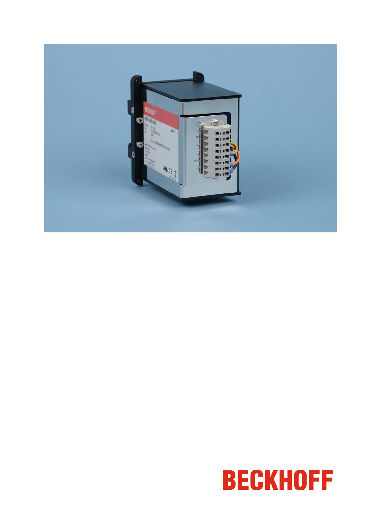
C9900-U332-0010 battery pack
Version: 1.2
Date: 2015-02-17
Page 2

Page 3

Table of contents
Table of contents
1 Foreword 3
1.1 Notes on the Documentation 3
1.1.1 Liability Conditions 3
1.1.2 Trademarks 3
1.1.3 Patent Pending 3
1.1.4 Copyright 3
1.1.5 State at Delivery 3
1.1.6 Delivery conditions 3
1.2 Description of safety symbols 4
1.3 Basic safety measures 5
1.4 Operator’s obligation to exercise diligence 5
1.4.1 National regulations 5
2 Product Description 6
3 Installation 7
3.1 Transport and Unpacking 7
3.1.1 Transport 7
3.1.2 Unpacking 7
3.2 Mounting 8
3.2.1 Vertical Installation 8
3.2.2 Horizontal Installation 9
3.2.3 Modification of the mounting plate 9
3.3 Connecting the Battery Pack 11
3.3.1 Pin assignment of the Connector 11
4 Operating Instructions 12
4.1 Appropriate Use 12
4.2 Operation 12
4.3 Servicing and maintenance 12
4.3.1 Cleaning 12
4.3.2 Maintenance 12
4.4 Emergency procedures 12
4.5 Shutting down 12
4.5.1 Disposal 12
5 Assembly dimensions 13
6 Wiring diagram 14
7 Technical Data 15
C9900-U332-0010 1
Page 4

Table of contents
8 Appendix 16
8.1 Beckhoff Support and Service 16
8.1.1 Beckhoff branches and partner companies 16
8.1.2 Beckhoff company headquarters 16
8.2 Approvals for USA and Canada 17
8.3 FCC Approvals for the United States of America 17
8.4 FCC Approval for Canada 17
2 C9900-U332-0010
Page 5

Foreword
1 Foreword
1.1 Notes on the Documentation
This description is only intended for the use of trained specialists in control and automation engineering
who are familiar with the applicable national standards. It is essential that the following notes and
explanations are followed when installing and commissioning these components.
The responsible staff must ensure that the application or use of the products described satisfy all the
requirements for safety, including all the relevant laws, regulations, guidelines and standards.
1.1.1 Liability Conditions
The documentation has been prepared with care. The products described are, however, constantly under
development. For that reason the documentation is not in every case checked for consistency with
performance data, standards or other characteristics. In the event that it contains technical or editorial
errors, we retain the right to make alterations at any time and without warning. No claims for the
modification of products that have already been supplied may be made on the basis of the data, diagrams
and descriptions in this documentation.
1.1.2 Trademarks
Beckhoff®, TwinCAT®, EtherCAT®, Safety over EtherCAT®, TwinSAFE® and XFC® are registered
trademarks of and licensed by Beckhoff Automation GmbH.
Other designations used in this publication may be trademarks whose use by third parties for their own
purposes could violate the rights of the owners.
1.1.3 Patent Pending
The EtherCAT Technology is covered, including but not limited to the following patent applications and
patents: EP1590927, EP1789857, DE102004044764, DE102007017835 with corresponding applications
or registrations in various other countries.
The TwinCAT Technology is covered, including but not limited to the following patent applications and
patents: EP0851348, US6167425 with corresponding applications or registrations in various other
countries.
1.1.4 Copyright
©
Beckhoff Automation GmbH & Co. KG.
The reproduction, distribution and utilization of this document as well as the communication of its contents
to others without express authorization are prohibited. Offenders will be held liable for the payment of
damages. All rights reserved in the event of the grant of a patent, utility model or design.
1.1.5 State at Delivery
All the components are supplied in particular hardware and software configurations appropriate for the
application. Modifications to hardware or software configurations other than those described in the
documentation are not permitted, and nullify the liability of Beckhoff Automation GmbH & Co. KG.
1.1.6 Delivery conditions
In addition, the general delivery conditions of the company Beckhoff Automation GmbH & Co. KG apply.
C9900-U332-0010 3
Page 6
Foreword
1.2 Description of safety symbols
The following safety symbols are used in this operating manual. They are intended to alert the reader to
the associated safety instructions.
Acute risk of injury!
If you do not adhere the safety advise adjoining this symbol, there is immediate
DANGER
WARNING
CAUTION
danger to life and health of individuals!
Risk of injury!
If you do not adhere the safety advise adjoining this symbol, there is danger to life and
health of individuals!
Hazard to individuals!
If you do not adhere the safety advise adjoining this symbol, there is obvious hazard to
individuals!
Hazard to devices and environment
Attention
Note
If you do not adhere the notice adjoining this symbol, there is obvious hazard to
materials and environment.
Note or pointer
This symbol indicates information that contributes to better understanding.
4 C9900-U332-0010
Page 7
Foreword
1.3 Basic safety measures
Appropriate Use
The battery pack C9900-U332-0010 is designed for use with the following devices with
Note
DANGER
Attention
Intel® Atom™ processor: CP62xx-xxxx-0020 und C6915.
Switch off the power supply of the Industrial PC during installation
During installation and removal of the battery pack, the power supply of the Industrial
PC must be switched off.
Only appropriately trained staff may install the battery pack
The operator must ensure that only appropriately trained electricians deal with
installation and wiring of the battery pack.
Ventilation of the battery pack location
When storing, installing and operating the battery pack, the regulations of VDE 0510
Attention
Part 2 / EN 50272-2 or the applicable national regulations must be complied with.
It must be ensured that the battery pack location is suitably ventilated.
1.4 Operator’s obligation to exercise diligence
The operator must ensure that
• the product is only used as intended (see chapter Product Description)
• the product is in a sound condition and in working order during operation
• the product is operated, maintained and repaired only by suitably qualified and authorized
personnel
• the personnel is instructed regularly about relevant occupational safety and environmental
protection aspects, and is familiar with the operating manual and in particular the safety notes
contained herein
• the operation manual is in good condition and complete, and always available for reference at the
location of the product.
Do not open the housing of the battery pack!
For technical support contact Beckhoff Service.
Note
1.4.1 National regulations
Depending on the type of machine and plant in which the Industrial PC is used, national regulations
governing the controllers of such machines will apply, and must be observed by the operator. These
regulations cover, amongst other things, the intervals between inspections of the controller. The operator
must initiate such inspections in good time.
C9900-U332-0010 5
Page 8

Product Description
2 Product Description
Front view of C9900-U332-0010
Industrial PCs can be equipped with a 24 V power supply unit and an integrated UPS. The UPS supplies
the PC with power if the mains power fails. This allows data to be saved on the hard disk or Flash, after
which the PC can be shut down properly.
A battery pack, which serves as the energy storage device, is mounted on a DIN rail outside the PC. With
its rated capacity of 1.3 Ah, the very compact C9900-U332-0010 24 V battery pack is designed for PCs
with Intel® Atom™ processor.
The battery pack offers the following benefits:
• battery pack for PCs with 24 V power supply with integrated UPS
• metal housing for mounting on norm rail TS35 x 15
• optional vertical or horizontal mounting
• two 12 V batteries in series connection
• VRLA AGM Technology = valve regulated lead acid batteries with glass fiber mat inside the
separator (VRLA = valve regulated lead acid, AGM = absorbed glass mat technology).
6 C9900-U332-0010
Page 9
Installation
3 Installation
3.1 Transport and Unpacking
The specified storage conditions must be observed (see chapter Technical Data).
3.1.1 Transport
Despite the robust design of the unit, the components are sensitive to strong vibrations and impacts.
During transport, your device should therefore be protected from excessive mechanical stress. Therefore,
please use the original packaging.
Danger of damage to the unit
If the device is transported in cold weather or is exposed to extreme variations in
Attention
Prior to operation, the unit must be allowed to slowly adjust to room temperature. Should condensation
occur, a delay time of approximately 12 hours must be allowed before the unit is switched on.
temperature, make sure that moisture (condensation) does not form on or inside the
device.
3.1.2 Unpacking
Proceed as follows to unpack the unit:
1. Remove packaging.
2. Do not discard the original packaging. Keep it for future relocation.
3. Check the delivery for completeness by comparing it with your order.
4. Please keep the associated paperwork. It contains important information for handling the unit.
5. Check the contents for visible shipping damage.
If you notice any shipping damage or inconsistencies between the contents and your order, you should
notify Beckhoff Service.
C9900-U332-0010 7
Page 10

Installation
3.2 Mounting
On delivery the battery pack C9900-U332-0010 is provided for vertical installation. By modification of the
mounting plate the battery pack can also be used for horizontal installation on the top hat rail.
Circulation of air
Note
Attention
3.2.1 Vertical Installation
Battery pack
C9900-U332-0010,
vertical installation
on delivery
When the unit is installed in an enclosure, adequate space for ventilation must be
provided.
Avoid extreme environmental conditions
Extreme environmental conditions should be avoided as far as possible. Protect the
battery pack from dust, moisture and heat.
2
1
3
The electrical connections (1) are located at the front of the unit.
The rear of the battery pack is installed on a top hat rail (2) of type TS 35 x 15 in the control cabinet. The
battery pack is fixed on the rail from the front side with the four allen screws (3), using an allen wrench
size 3.0.
8 C9900-U332-0010
Page 11

Installation
3.2.2 Horizontal Installation
After modification of the mounting plate (see also chapter Modification of the mounting plate) the battery pack can be installed in horizontale position on the top hat rail.
Battery pack
C9900-U332-0010,
horizontal installation
2
1
3
The electrical connections (1) are located at the front of the unit.
The rear of the battery pack is installed on a top hat rail (2) of type TS 35 x 15 in the control cabinet. The
battery pack is fixed on the rail from the front side with the four allen screws (3), using an allen wrench
size 3.0.
3.2.3 Modification of the mounting plate
After modification of the mounting plate the battery pack can be installed in horizontal position on the top
hat rail. Procceed as follows:
Rear view,
vertical orientation
on delivery
2
2
1
1. Remove the sheet for the ground connection (1), using an allen wrench size 3.0.
2. Remove the two mounting notches (2), using an allen wrench size 2.5.
3. Rotate the battery pack about 90 degrees as shown on the following picture.
C9900-U332-0010 9
Page 12

Installation
Rear view,
horizontal orientation
2
2
1
5. Mount the sheet for the ground connection (1) at the position shown on the picture, using an allen
wrench size 3.0.
6. Mount the two mounting notches (2), using an allen wrench size 2.5.
The battery pack can now be installed on the top hat rail.
10 C9900-U332-0010
Page 13

Installation
3.3 Connecting the Battery Pack
Connecting cables
Please read the documentation for the external devices prior to connecting them!
Attention
3.3.1 Pin assignment of the Connector
The 8-pin terminal strip (X101) shown in the photograph is mounted on the battery pack housing for
connecting the pack with the power supply unit of the Industrial PC.
During thunderstorms, plug connector must neither be inserted nor removed!
Disconnect the devices from the power supply!
When disconnecting a plug connector, always handle it at the plug. Do not pull the
cable!
Connection terminal strip at
the battery pack
Loop through the cables
Note
Only the functions BAT+, BAT- and protective ground are directly wired with the battery
pack. The other terminals can be used for looping through the cable set.
Conductive cross-section
Pin Function
1
2
3
4
5
6
7
8
-
+
UPS+ (Output)
-
+
PC_ON
Power-Status
BAT
24 V DC
Power Supply
The connector is specified for 16 A and can lift conductive cross-sections until 1.5 mm
2
.
Note
C9900-U332-0010 11
Page 14

Operating Instructions
4 Operating Instructions
4.1 Appropriate Use
The battery pack C9900-U332-0010 is designed for use with the following devices with Intel® Atom™
processor: CP62xx-xxxx-0020 und C6915.
4.2 Operation
For operation, please read the appropriate power supply manual.
4.3 Servicing and maintenance
4.3.1 Cleaning
Disconnect power supply
Switch off the device and all connected devices, and disconnect the device from the
DANGER
The device can be cleaned with a soft, damp cleaning cloth. Do not use any aggressive cleaning
materials, thinners, scouring material or hard objects that could cause scratches.
power supply.
4.3.2 Maintenance
The battery pack is maintenance-free.
4.4 Emergency procedures
In case of fire, the battery pack should be extinguished with dry chemical, foam, halon or CO2 .
Special Fire Fighting Procedures
Turn off power! Use positive pressure, self-contained breathing apparatus in fighting
DANGER
fire! Water applied to electrolyte generates heat and causes it to splatter! Wear acid
resistant clothing! Ventilate area well!
4.5 Shutting down
4.5.1 Disposal
Observe national electronics scrap regulations
Observe the national electronics scrap regulations when disposing of the device.
Note
In order to dispose of the device, it must be removed and fully dismantled:
• Housing components (polycarbonate, polyamide (PA6.6)) are suitable for plastic recycling.
• Metal parts can be sent for metal recycling.
• Electronic parts such as disk drives and circuit boards must be disposed of in accordance with
national electronics scrap regulations.
12 C9900-U332-0010
Page 15

Assembly dimensions
5 Assembly dimensions
Notice mounting orientation
The assembly of the unit must take place with the orientation diagrammed here.
Warning
Battery pack C9900-U332-0010 (maximum device dimensions in mm)
Vertical installation on top hat rail
Horizontal installation on top hat rail
Hole pattern for mounting without top hat rail
C9900-U332-0010 13
Page 16
Wiring diagram
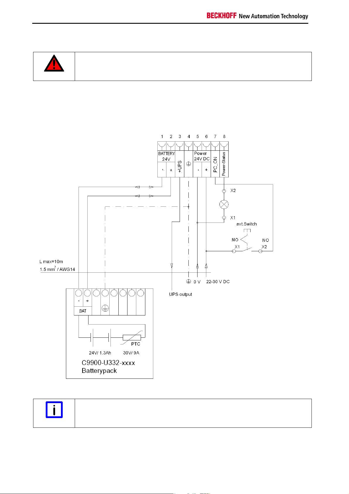
6 Wiring diagram
Risk of explosion!
Do not use the battery pack in areas of explosive hazard!
Danger
Wiring diagram external switch and power supply
Wiring according to the wiring diagram (the circuit of PC_ON and Power-Status is symbolical):
Connection of the Battery Pack and UPS Output
Connection of the battery pack and UPS Output only in combination with integrated UPS
Note
(order option).
14 C9900-U332-0010
Page 17
Technical Data
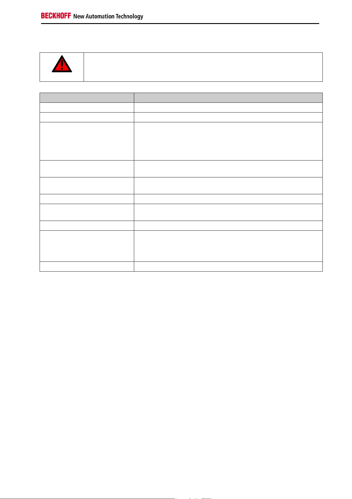
7 Technical Data
Risk of explosion!
Do not use the battery pack in areas of explosive hazard!
Danger
Product name C9900-U332-0010
Dimensions (B x H x T) see chapter Assembly dimensions
Weight 2.4 kg
Electrical data Nominal voltage: 24 V
Capacity: 1,3 Ah (discharge over 20 hours)
Internal resistance: 180 mOhm
Protection: 9 A/ 30 V via PTC element
Final charge voltage: between 27.2 V and 27.4 V
Shock resistance
(Sinusoidal vibration)
Shock resistance
(Shock)
EMC compatibility Resistance to interference conforms to EN 61000-6-2
Permissible ambient temperature 0°C to +50°C (operation)
Permissible relative humidity to 95%, no condensation
Transport and storage The same values for atmospheric humidity and shock resistance are
Certifications CE, UL
EN 60068-2-6: 10 to 58 Hz: 0,035 mm
58 to 500 Hz: 0,5 G (~ 5 m/ s
2
)
EN 60068-2-27: 5 G (~ 50 m/ s2), duration: 30 ms
0°C to +50°C (transport/ storage)
to be observed during transport and storage as in operation. Suitable
packaging of the battery pack can improve the resistance to impact
during transport.
C9900-U332-0010 15
Page 18

Appendix
8 Appendix
8.1 Beckhoff Support and Service
Beckhoff and their partners around the world offer comprehensive support and service, making available
fast and competent assistance with all questions related to Beckhoff products and system solutions.
8.1.1 Beckhoff branches and partner companies
Please contact your Beckhoff branch office or partner company for local support and service on Beckhoff
products!
The contact addresses for your country can be found in the list of Beckhoff branches and partner
companies: www.beckhoff.com
8.1.2 Beckhoff company headquarters
Beckhoff Automation GmbH & Co. KG
Huelshorstweg 20
33415 Verl
Germany
. You will also find further documentation for Beckhoff components there.
Phone: + 49 (0) 5246/963-0
Fax: + 49 (0) 5246/963-198
E-mail: info@beckhoff.de
Web: http://www.beckhoff.de/
Beckhoff Support
Support offers you comprehensive technical assistance, helping you not only with the application of
individual Beckhoff products, but also with other, wide-ranging services:
• world-wide support
• design, programming and commissioning of complex automation systems
• and extensive training program for Beckhoff system components
Hotline: + 49 (0) 5246/963-157
Fax: + 49 (0) 5246/963-9157
E-mail: support@beckhoff.com
Beckhoff Service
The Beckhoff Service Center supports you in all matters of after-sales service:
• on-site service
• repair service
• spare parts service
• hotline service
Hotline: + 49 (0) 5246/963-460
Fax: + 49 (0) 5246/963-479
E-mail: service@beckhoff.com
If servicing is required, please quote the project number of your product.
16 C9900-U332-0010
Page 19

Appendix
8.2 Approvals for USA and Canada
8.3 FCC Approvals for the United States of America
FCC: Federal Communications Commission Radio Frequency Interference Statement
This equipment has been tested and found to comply with the limits for a Class A digital device, pursuant
to Part 15 of the FCC Rules. These limits are designed to provide reasonable protection against harmful
interference when the equipment is operated in a commercial environment. This equipment generates,
uses, and can radiate radio frequency energy and, if not installed and used in accordance with the
instruction manual, may cause harmful interference to radio communications. Operation of this equipment
in a residential area is likely to cause harmful interference in which case the user will be required to
correct the interference at his own expense.
Technical modifications
Technological changes to the device may cause the loss of the FCC approval.
Note
8.4 FCC Approval for Canada
FCC: Canadian Notice
This equipment does not exceed the Class A limits for radiated emissions as described in the Radio
Interference Regulations of the Canadian Department of Communications.
C9900-U332-0010 17
 Loading...