

Page 1
Installation and Operating instructions for
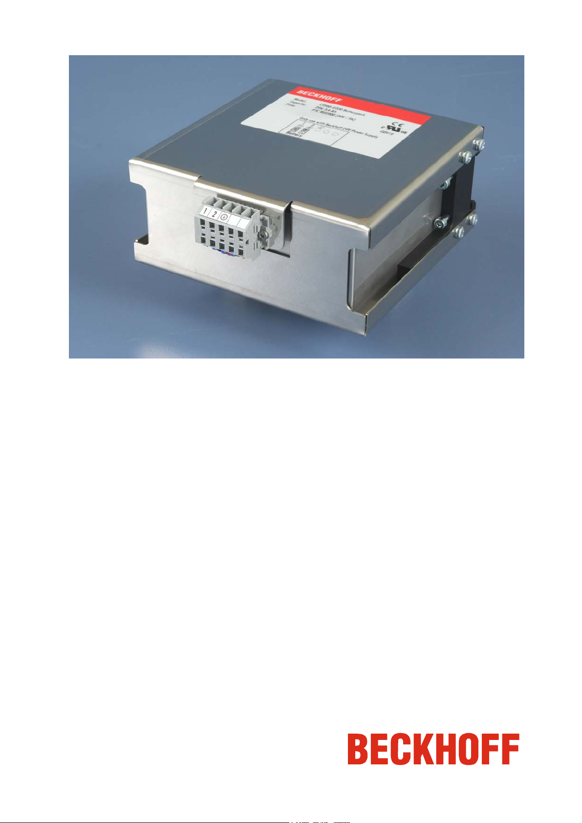
C9900-U330-0010 battery pack
Version: 1.8
Date: 2015-02-17
Page 2

Page 3

Table of contents
Table of contents
1.
General Notes 2
Notes on the documentation 2
Liability Conditions 2
Description of safety symbols 2
Basic safety measures 3
Operator's obligation to exercise diligence 3
2.
Installation Instructions 4
Appropriate Use 4
Configuration and installation 4
Connecting the battery pack 5
Connection with the Industrial PC 5
Power supply of the Industrial PC 5
Fitting the Power Supply Cable 5
Connector installation 6
Cable cross-sections 6
3.
Operating Instructions 7
Appropriate Use 7
Operation 7
Servicing 7
Shutting down 7
Disposal 7
4.
Troubleshooting 8
Service and Support 8
Beckhoff's branch offices and representatives 8
Beckhoff headquarters 8
Beckhoff Support 8
Beckhoff Service 8
5.
Assembly dimensions 9
6.
Wiring diagram 9
7.
Appendix 10
Technical data 10
Approvals 10
FCC: Federal Communications Commission 10
Radio Frequency Interference Statement 10
FCC: Canadian Notice 10
C9900-U330-0010 1
Page 4
General Notes
General Notes
Notes on the documentation
This description is only intended for the use of trained specialists in control
and automation engineering who are familiar with the applicable national
standards. It is essential that the following notes and explanations are
followed when installing and commissioning these components.
Liability Conditions
The responsible staff must ensure that the application or use of the
products described satisfy all the requirements for safety, including all the
relevant laws, regulations, guidelines and standards.
The documentation has been prepared with care. The products described
are, however, constantly under development. For this reason, the
documentation may not always be have been fully checked for consistency
with the performance data, standards or other characteristics described.
None of the statements in this manual represent a guarantee for as set out
in § 443 of the German Civil Code or a statement about the assumed use
according to the contract as set out in § 434 para. 1 clause 1 no. 1 of the
German Civil Code. In the event that it contains technical or editorial errors,
we retain the right to make alterations at any time and without warning. No
claims for the modification of products that have already been supplied
may be made on the basis of the data, diagrams and descriptions in this
documentation.
© This documentation is protected by copyright. Any reproduction or third
party use of this publication, whether in whole or in part, without the written
permission of Beckhoff Automation GmbH & Co. KG, is forbidden.
Description of safety symbols
The following safety symbols are used in this operating manual. They are
intended to alert the reader to the associated safety instructions.
This symbol is intended to highlight risks for the life or health of personnel.
This symbol is intended to highlight risks for equipment, materials or the
environment.
This symbol indicates information that contributes to better understanding.
i
Danger
Warning
Note
2 C9900-U330-0010
Page 5

General Notes
Basic safety measures
The battery pack must only be used in conjunction with the C9900-
i
Note
P209, C9900-P214, C9900-P216 or C9900-P218 power supply unit!
Switch off the power supply of the Industrial PC during installation!
Danger
During installation and removal of the battery pack, the power supply of the
Industrial PC must be switched off.
Ventilation of the battery pack location
Achtung
When storing, installing and operating the battery pack, the regulations of
VDE 0510 Part 2 / EN 50272-2 or the applicable national regulations must
be complied with.
It must be ensured that the battery pack location is suitably ventilated.
Operator's obligation to exercise diligence
Only appropriately trained staff may install the battery pack!
Warning
The operator must ensure that only appropriately trained electricians deal
with installation and wiring of the battery pack.
C9900-U330-0010 3
Page 6

Installation Instructions
Installation Instructions
Appropriate Use
The C9900-U330-0010 battery pack is designed for installation in machine
and plant technology control cabinets in conjunction with the C9900-P209,
C9900-P214, C9900-P216 or C9900-P218 power supply unit.
Configuration and installation
C9900-U330-0010 battery
pack
The electrical connections (1) are located at the front of the unit. The rear
of the battery pack is installed on a top hat rail (2) in the control cabinet.
Top hat rail installation
2
1
2
1
2
For installation in the control cabinet, the rear of the battery pack is hung
into a TS 35 x 15 type top hat rail (1). The battery pack is secured on the
rail and the ground connection with the control cabinet is established by
tightening the four hexagon socket screws (2) on both sides of the housing.
4 C9900-U330-0010
Page 7

Installation Instructions
Connecting the battery pack
Connection with the Industrial PC
The 5-pin 2-wire terminal strip with mounting flanges shown in the
photograph is mounted on the battery pack housing for connecting the
pack with the power supply unit of the Industrial PC.
Connection terminal strip at
the battery pack
5
4
3
2
1
Power supply of the Industrial PC
The 5-pin CAGE CLAMP plug connector and mounting flange illustrated is
located on the PC housing in order to connect the power supply.
Pin assignment for the
24 VDC power supply unit
2
5
3
4
1
Pin Function
Pin Function
1
2
3
4
5
1
2
3
5
6
-
+
not used
not used
+
-
+
-
24 V Battery Pack
24 V DC
Power supply
24 V Battery pack
Wiring according to the
wiring diagram
Materials for assembly of
the connector
Fitting the Power Supply Cable
Install the cable for the power supply of the Industrial PC or the connection
between the Industrial PC and battery pack according to the Wiring
diagram using the connector assembly material provided.
A
B
Female plug connector
C
Strain relief housing
D
C9900-U330-0010 5
Page 8

Installation Instructions
Connector installation
Fitting the connector to the
cable
Applying the strain relief
The plug is fitted to the cable as follows:
1. Remove the insulation from the cable ends (8 - 9 mm).
2. Push the cable into the holders, applying slight pressure according
to the pin assignment label and the wiring diagram.
3. Push the lower part (part A) of the strain relief housing onto the top
of the female plug connector until it snaps into place.
4. Relieve the strain on the supply cable by fixing it in place with the
cable clamp (part C) and fixing screws (part D) (see photograph
below).
Fix the upper part (part B) of the strain relief housing by snapping it onto
the lower part.
Cable cross-sections
Use cables with a cross-section of at least 1.5 mm
supply lines to the Industrial PC. For greater distances between the battery
pack and the PC, cables with a cross section of 2.5 mm
be used, in order to avoid excessive voltage drop in the cable.
2
(AWG 16) for the
2
(AWG 14) should
6 C9900-U330-0010
Page 9

Operating Instructions
Operating Instructions
Appropriate Use
The C9900-U330-0010 battery pack is designed for installation in machine
and plant technology control cabinets in conjunction with the C9900-P209,
C9900-P214, C9900-P216 or C9900-P218 power supply unit.
Operation
For operation, please read the appropriate power supply manual.
Servicing
The battery pack is maintenance-free.
Shutting down
Dismantling the case
Observe national
electronics scrap
regulations
Disposal
For disposal, the housing must be completely dismantled and the
rechargeable lead gel battery removed. The housing can be sent for metal
recycling.
The lead gel battery must be disposed of according to the national
electronic scrap regulations.
C9900-U330-0010 7
Page 10

Troubleshooting
Troubleshooting
In the event of a fault contact your Beckhoff Service.
Service and Support
Beckhoff and their partners around the world offer comprehensive service
and support, making available fast and competent assistance with all
questions related to Beckhoff products and system solutions.
Beckhoff's branch offices and representatives
Please contact your Beckhoff branch office or representative for local
support and service on Beckhoff products!
The addresses of Beckhoff's branch offices and representatives round the
world can be found on her internet pages:
http://www.beckhoff.com
You will also find further documentation
Beckhoff headquarters
Beckhoff Automation GmbH & Co. KG
Huelshorstweg 20
D-33415 Verl
Germany
Phone:
Fax: +49(0)5246/963-198
e-mail: info@beckhoff.com
+49(0)5246/963-0
Beckhoff Support
Support offers you comprehensive technical assistance, helping you no
only with the application of individual Beckhoff products, but also with
other, wide-ranging services:
• world-wide support
• design, programming and commissioning of complex automation
systems
• and extensive training program for Beckhoff system components
Hotline:
Fax: +49(0)5246/963-9157
e-mail: support@beckhoff.com
+49(0)5246/963-157
Beckhoff Service
The Beckhoff Service Center supports you in all matters of after-sales
service:
• on-site service
• repair service
• spare parts service
• hotline service
Hotline:
Fax: +49(0)5246/963-479
e-mail: service@beckhoff.com
Quote the project number If servicing is required, please quote the project number of your Industrial
PC.
+49(0)5246/963-460
for Beckhoff components there.
8 C9900-U330-0010
Page 11

Assembly dimensions
Assembly dimensions
Maximum device dimensions in mm.
C9900-U330-0010 battery
pack
Wiring diagram
C9900-U330-0010 9
Page 12

Appendix
Appendix
Technical data
Electrical data Nominal voltage: 24 V
Capacity: 3.4 Ah (discharge over 20 hours)
Internal resistance: 120 mOhm
Protection: 9 A/ 30 V via PTC element
Final charge voltage: between 27.2 V and 27.4 V
Dimensions Dimensions (W x H x D): 160.65 x 69.60 x 171.00 mm
Weight: 3.3 kg
Do not use the battery pack
in areas of explosive
hazard
Environmental conditions Ambient temperature: 0 to 50°C
Shock resistance
The battery pack must not be used where there is a risk of explosion.
The following conditions must be observed during operation:
Atmospheric humidity: Maximum 95%, non-condensing
Sinusoidal vibration
(EN 60068-2-6):
58 to 500 Hz: 0.5 G (~ 5 m/ s2)
Impact
(EN 60068-2-27):
10 to 58 Hz: 0.035 mm
5 G (~ 50 m/ s²), duration: 30 ms
Compatibility Resistance to interference: according to EN 61000-6-2
Transport and storage The same values for atmospheric humidity and shock resistance are to be
observed during transport and storage as in operation. The shock
resistance during transport can be improved by appropriate packaging of
the battery pack. The ambient temperature during storage and transport
must be between -20°C and +65°C.
Approvals
FCC: Federal Communications Commission
Radio Frequency Interference Statement
FCC Approval for USA This equipment has been tested and found to comply with the limits for a
Class A digital device, pursuant to Part 15 of the FCC Rules. These limits
are designed to provide reasonable protection against harmful interference
when the equipment is operated in a commercial environment. This
equipment generates, uses, and can radiate radio frequency energy and, if
not installed and used in accordance with the instruction manual, may
cause harmful interference to radio communications. Operation of this
equipment in a residential area is likely to cause harmful interference in
which case the user will be required to correct the interference at his own
expense.
FCC: Canadian Notice
FCC Approval for Canada This equipment does not exceed the Class A limits for radiated emissions
as described in the Radio Interference Regulations of the Canadian
Department of Communications.
10 C9900-U330-0010
 Loading...