

Page 1
External Brake Resistor AX2090-BW5x-xxxx BECKHOFF Drive Technology
Technical Documentation
Eiserstr. 5
Version: 1.0 33415 Verl
Date: 11.9.2009 Germany
Language: EN
Article no.: TDenAX-2090-BW5x-0400 Phone: +49(0)5246/963-0
Fax: +49(0)5246/963-198
e-mail: Info@beckhoff.com
Internet: www.beckhoff.com
Beckhoff Automation GmbH
Please read carefully before commissioning!
Foreword
Liability conditions
The responsible staff must ensure that the application or use of the products described satisfy all the requirements for safety, including all the
relevant laws, regulations and guidelines.
The documentation has been prepared with care. The products described are, however, constantly under development. For this reason, the
documentation may not always be have been fully checked for consistency with the performance data, standards or other characteristics described.
None of the statements in this manual represent a guarantee for as set out in § 443 of the German Civil Code or a statement about the assumed
use according to the contract as set out in § 434 para. 1 clause 1 no. 1 of the German Civil Code. In the event that it contains technical or editorial
errors, we retain the right to make alterations at any time and without warning. No claims for the modification of products that have already been
supplied may be made on the basis of the data, diagrams and descriptions in this documentation.
Copyright
© These instructions are protected by copyright. Any reproduction or third party use of this publication, whether in whole or in part, without the
written permission of Beckhoff Automation GmbH, is forbidden.
Appropriate use
The brake resistors from the AX2090-BW5x-xxxx series are exclusively designed for direct application with an AX5000 series servo drive or the
AX5021 brake module. They are designed for installation as components in electrical installations and machines together with the servo drive or the
brake module, and this is their only purpose.
Scope of supply
The scope of supply includes the following components:
Brake resistor from the required performance class, technical documentation and packaging
If one of the components is damaged please notify the logistics company and Beckhoff Automation GmbH immediately.
Security
Safety rules
The responsible staff must ensure that the application or use of the products described satisfy all the requirements for safety, including all the
relevant laws, regulations and guidelines.
Caution – Danger of death!
Even when the AX5000 is disconnected from the mains voltage, dangerous voltage continues to be present at the "X02" terminals
DANGER
WARNING
Exclusion of liability
All the components are supplied in particular hardware and software configurations appropriate for the application. Modifications to hardware or
software configurations other than those described in the documentation are not permitted, and nullify the liability of Beckhoff Automation GmbH.
Personnel qualification
This description is only intended for trained specialists in control, automation and drive engineering who are familiar with the applicable national
standards. Knowledge of machine safety legislation is compulsory.
Product description
Warning
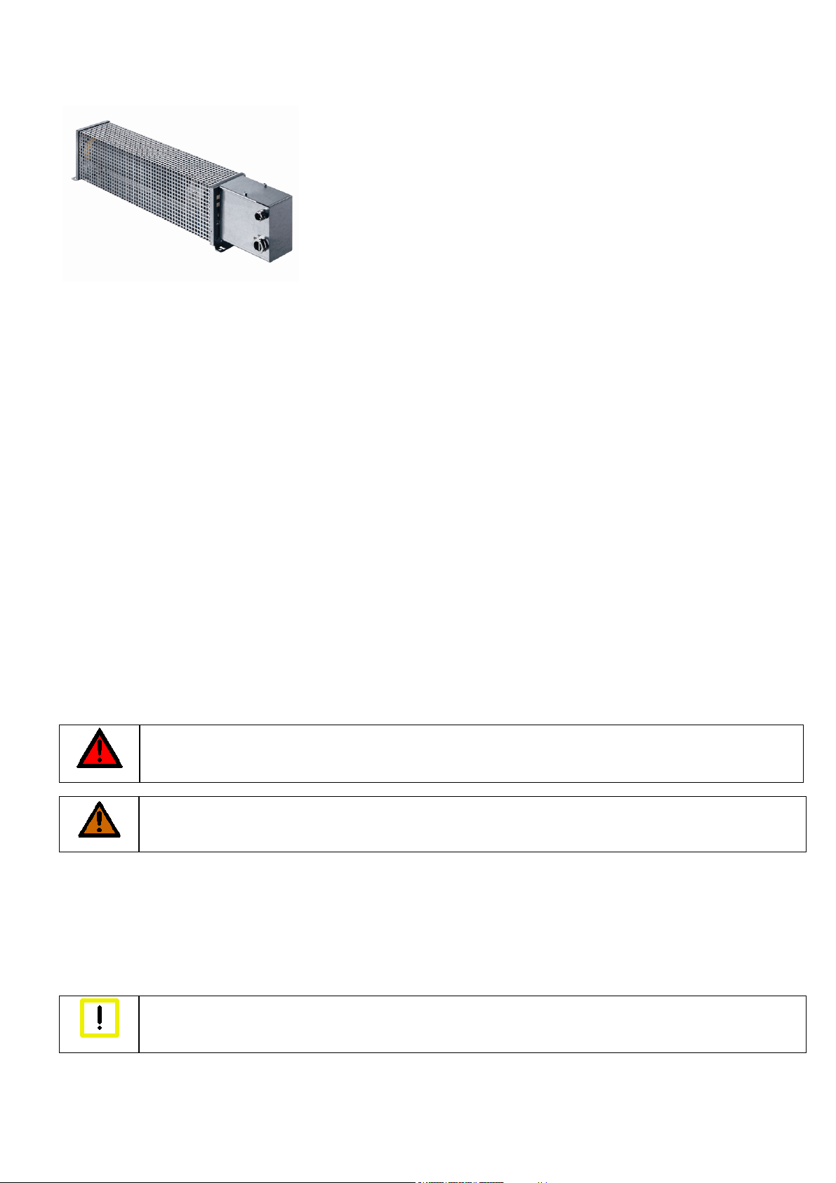
The external brake resistors of the AX2090-BW5x-xxxx series are able to convert the dynamic energy generated during braking of a servomotor into
heat. The series covers a wide continuous power and peak power range. The built-in temperature switch enables the system to respond
immediately to any overload of the brake resistor through analysis in the AX5000 or the PLC. All brake resistors of the AX2090-BW5x-xxxx series
are UL and CSA approved.
of the DC link for at least 5 minutes. Never touch the terminals within this period.
Caution - Risk of injury through hot surfaces!
The temperature of the brake resistor housing surface may reach over 200 °C. Please ensure that the housing has cooled down
below 40 °C before touching it.
Caution - Destruction of the equipment
The brake resistor may only be connected to individual AX5000 devices or AX5021 brake modules. It must never be used in a drive
system without the AX5021 brake module, since this may lead to its destruction through overload.
Page 2
Page 2/4
Caution - Destruction of the brake resistor and consequential damage
The built-in temperature switch must be monitored, so that the machine can be stopped in a controlled manner and switched off in
the event of an overloading of the brake resistor.
Warning
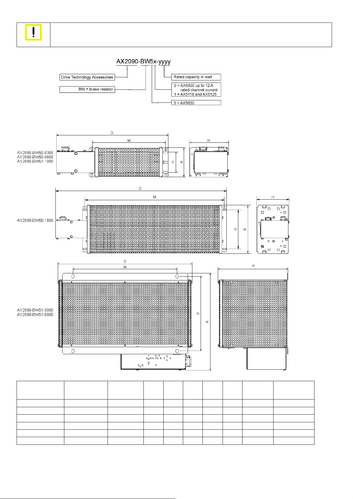
Type key
Mechanical installation
Dimensions and technical data
Dimensions and technical data
Type Nominal capacity
[W]
*
Resistance [Ω]
O [mm] R [mm] H [mm] M [mm] U [mm] Weight [kg] AX5000
at 40° C
AX2090-BW50-0300 300 47 349 92 120 230 64 2 AX5x01-AX5112
AX2090-BW50-0600 600 47 549 92 120 430 64 3 AX5x01-AX5112
AX2090-BW50-1600 1600 47 649 185 120 530 150 5,8 AX5x01-AX5112
AX2090-BW51-1000 1000 23 749 92 120 630 64 4 AX5118, AX5125
AX2090-BW51-3000 3000 23,4 490 355 255 380 270 8 AX5118, AX5125
AX2090-BW51-6000 6000 23,2 490 455 255 380 370 12 AX5118, AX5125
*) 4% output reduction per 10 K temperature difference
Page 3
Page 3/4
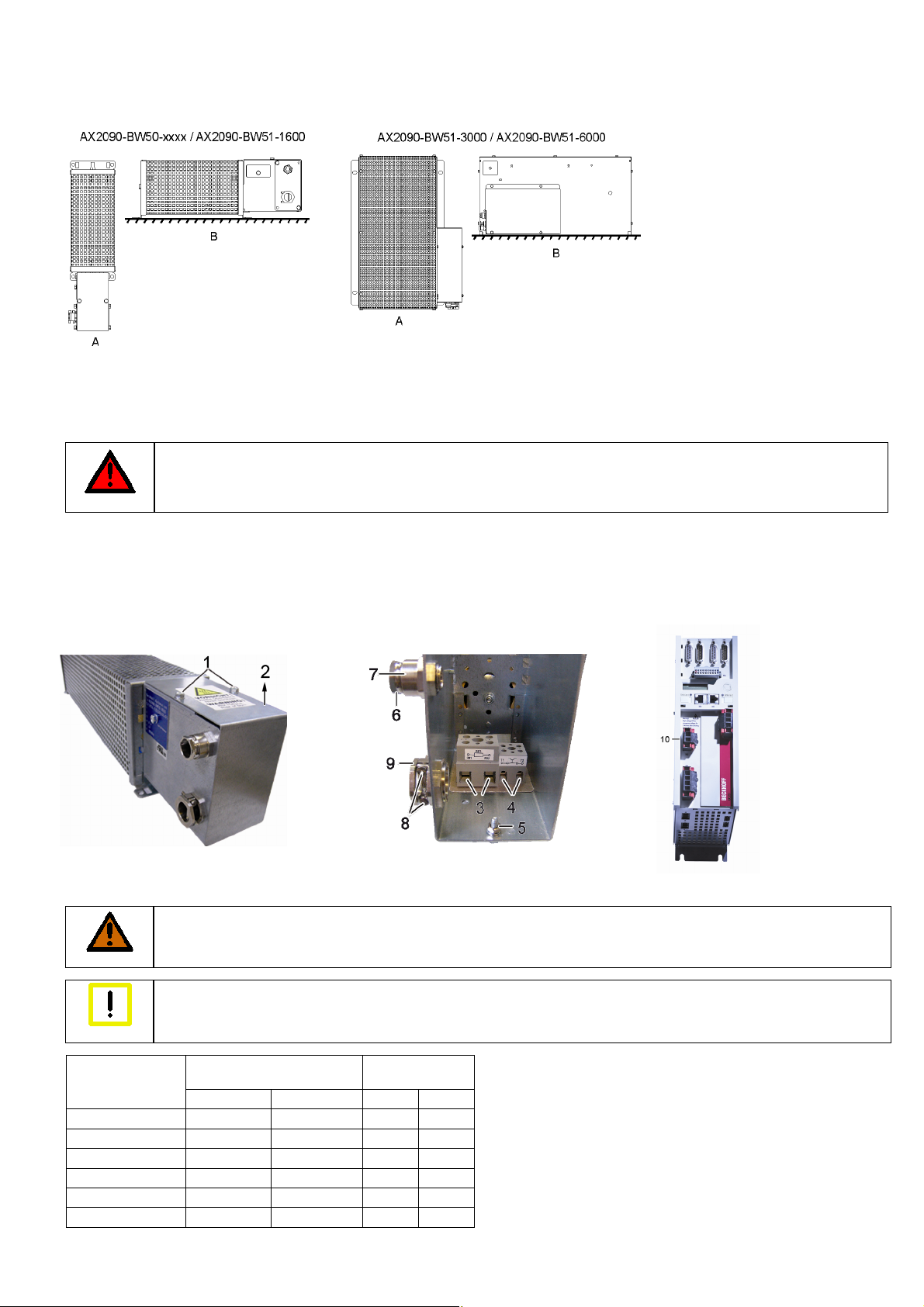
Mounting positions and distances
(A) = vertical installation is only permitted according to the diagram (terminal box facing downwards).
(B) = horizontal installation
For all mounting positions the following minimum distances must be adhered to:
200 mm to adjacent components, walls etc. and 300 mm to components, ceilings etc. above. If the device is installed vertically (A), the minimum
distance to components, floors etc. below is 200 mm in order to allow unobstructed flow of air to the brake resistor.
Electrical installation
Caution – Danger of death!
Disconnect the AX5000 from the mains before installing the brake resistor!
Even when the AX5000 is disconnected from the mains voltage, dangerous voltage continues to be present at the "X02" terminals
DANGER
Remove the two screws (1) and remove the cover (2) in direction of the arrow. Connect an adequately dimensioned cable (see section Cables) to
the terminals (3) of the resistor and the earthing stud (5) and take it out of the terminal box through the strain-relief assembly (9). Ensure adequate
strain relief with the two screws (8). Connect the other side of the cable to the DC link contact connector X2 (10) of the AX5000. The connector is
supplied with the AX5000. Connect the earthing cable to the earthing conductor of the control cabinet.
Connect an adequately dimensioned cable to the potential-free N/C contact (4) of the temperature switch and take it out of the terminal box through
the strain-relief assembly (7) (see section Temperature switch). Ensure adequate strain relief with the nut (6).
Install the cover (2) in reverse order.
Cables
We recommend
WARNING
Warning
Type
AX2090-BW50-0300 1,5 16 0,75 18
AX2090-BW50-0600 1,5 16 0,75 18
AX2090-BW50-1600 1,5 16 0,75 18
AX2090-BW51-1000 2,5 12 0,75 18
AX2090-BW51-3000 2,5 12 0,75 18
AX2090-BW51-6000 2,5 12 0,75 18
We recommend wire end sleeves.
of the DC link for at least 5 minutes. Never touch the terminals within this period.
Beckhoff motor cables for connecting the brake resistors.
Caution - Fire hazard!
The brake resistors become very hot. Only use cables with adequate heat resistance.
EMC safety
Use only shielded cables.
Brake resistor Temperature
switch
2
[mm
] [AWG] [mm2] [AWG]
Page 4

Page 4/4
y cy
Temperature switch
Destruction of the brake resistor
The temperature switch is only used for temperature
monitoring. The brake resistor is not switched off.
Warning
The temperature switch has a potential-free N/C contact, which enables
immediate response to any overload of the brake resistor through analysis in
the AX5000 or the PLC. Connect the cable directly to a free input of plug "X06".
Then parameterise it such that the AX5000 stops the motor(s) with an
emergency ramp or the PLC reads and processes this input.
Short-term capacity
Type
AX2090-BW50-0300 180 2
AX2090-BW50-0600 180 2
AX2090-BW50-1600 180 2
AX2090-BW51-1000 180 2
AX2090-BW51-3000 85 2
AX2090-BW51-6000 85 2
Switching
temperature
[°C] [A]
Brake resistors are usually not operated continuously, but only exposed to short-time duty. In the following section the permitted short-term capacity
is calculated based on the continuous power, overload factor and duty cycle.
Duty cycle
The dut
y cycle is a relative value that depends on the switch-on time (t
)and the cycle time. Cycle times up to 120 sec. are used directly in the
on
calculation. Should the cycle time exceed 120 sec., the maximum relevant cycle time of 120 sec. is used in the calculation.
Example 1 Example 2
= 60 s ton = 40 s
t
on
Cycle time = 280 s Cycle time = 100 s
Dut
cle = 50 % Duty cycle = 40 %
Overload factor
Calculation formula:
Short-term capacity = continuous power x overload factor
Switching current
24 VDC or 230 VAC
Overtemperature and continuous power at 100% duty cycle
If your application requires a higher continuous power than the specified nominal capacity, you can accept this state if a higher brake resistor
temperature is permitted. The following diagram shows the overtemperature v. the continuous power.
Normal operating range, max. 130%:
This operating range is recommended for
maximum service life and error-free
operation.
Permitted operating range, max. 160%:
This operating range is still permitted,
although it results in shorter service life with
higher failure probability.
Inadmissible operating range, more than 160%:
In this operating range there is a risk of
destruction of the brake resistor through
overheating. Due to the high temperatures
the adjacent components are also at risk.
Destruction of the brake resistor and adjacent components
Always ensure adequate ventilation of the brake resistor, since the temperatures of the housing surface may exceed 200 °C.
Warning
 Loading...