

Page 1

Communication profile
PROFIBUS DP for
AX2000 / AX2500
Reference Guide, Setup
Keep all product manuals as a product component
during the life span of the servo amplifier.
Pass all product manuals to future
users / owners of the servo amplifier.
Edition 12/05
Page 2

Previous editions
Edition Comments
12/ 05 First version
SINEC is a registered trademark of Siemens AG
Technical changes to improve the performance of the equipment may be made without prior notice!
Printed in the Federal republic of Germany
All rights reserved. No part of this work may be reproduced in any form (by printing, photocopying, microfilm or any other
method) or stored, processed, copied or distributed by electronic means, without the written permission of BECKHOFF.
Page 3

BECKHOFF 12/05 Contents
page
1 General
1.1 About this manual ....................................................................... 5
1.2 Use as directed ......................................................................... 5
1.3 Symbols used in this manual ............................................................... 6
1.4 Abbreviations used in this manual ........................................................... 6
2 Installation / Setup
2.1 Installation ............................................................................. 7
2.1.1 Safety notes....................................................................... 7
2.1.2 Inserting the expansion card (AX2000) .................................................. 8
2.1.2.1 Front view ..................................................................... 8
2.1.2.2 Setup of Station Address and Baud Rate ............................................. 8
2.1.2.3 Connection technology ........................................................... 8
2.1.2.4 Connection diagram ............................................................. 9
2.1.3 Profibus master module setup ........................................................ 10
2.1.3.1 Configuration of the master controller ( e.g. Siemens S7)................................ 10
2.1.4 Standard function block for date exchange with the AX2000/2500 ............................ 11
2.2 Amplifier setup ......................................................................... 11
2.2.1 Guide to setup .................................................................... 11
2.2.2 Important amplifier configuration parameter.............................................. 12
2.2.3 Setup Software ................................................................... 13
2.2.3.1 Screen page PROFIBUS......................................................... 13
2.2.3.2 Screen page PROFIBUS instrument control .......................................... 14
3 Profile of AX2000/2500
3.1 Parameter channel...................................................................... 16
3.1.1 Parameter ID (PKE) ................................................................ 16
3.1.1.1 Interpretation of the response IDs .................................................. 16
3.1.1.2 Response ID 7: Profile specific error numbers ........................................ 17
3.1.2 Index IND........................................................................ 17
3.1.3 Parameter value PWE .............................................................. 18
3.2 The process data channel (PZD) ........................................................... 18
4 Using the parameter channel (PKW)
4.1 Read/write an amplifier parameter .......................................................... 19
4.2 Summary of the parameter numbers ........................................................ 19
4.2.1 List of the parameters .............................................................. 20
4.2.2 Standard PROFIDRIVE parameters ................................................... 22
4.2.2.1 PNU 940/911: PPO type write/read................................................. 22
4.2.2.2 PNU 918: PROFIBUS node address................................................ 22
4.2.2.3 PNU 963: baud rate............................................................. 22
4.2.2.4 PNU 965: PROFIDRIVE profile number ............................................. 22
4.2.2.5 PNU 970: default parameters ..................................................... 22
4.2.2.6 PNU 971: non volatile saving of parameters .......................................... 22
4.2.2.7 PNU 930: Selection Switch for Operating Mode ....................................... 23
4.2.3 Manufacturer specific parameters ..................................................... 24
4.2.3.1 PNU 1000: instrument ID ........................................................ 24
4.2.3.2 PNU 1001: manufacturer specific error register ....................................... 24
4.2.3.3 PNU 1002: manufacturer specific status register ...................................... 25
4.2.4 Position control parameters .......................................................... 26
4.2.4.1 PNU 1894: velocity multiplier...................................................... 26
4.2.4.2 PNU 1807: axis type ............................................................ 26
PROFIBUS for AX2000/2500 3
Page 4

Contents 12/05 BECKHOFF
page
4.2.5 Position data for the position control mode .............................................. 26
4.2.5.1 PNU 1790: position ............................................................. 26
4.2.5.2 PNU 1791: velocity ............................................................. 26
4.2.5.3 PNU 1785: motion task type ...................................................... 27
4.2.5.4 PNU 1783: acceleration time...................................................... 27
4.2.5.5 PNU 1784: acceleration jolt limiting................................................. 27
4.2.5.6 PNU 1786: deceleration time ..................................................... 28
4.2.5.7 PNU 1787: deceleration jolt limiting................................................. 28
4.2.5.8 PNU 1788: next motion task ...................................................... 28
4.2.5.9 PNU 1789: start delay ........................................................... 28
4.2.5.10 PNU 1310: copy motion task...................................................... 28
4.2.5.11 PNU 1311: position, 32 bit floating decimal point format................................. 28
4.2.5.12 PNU 1312: velocity, 32 bit floating decimal point format .................................28
4.2.6 Setup mode: position ............................................................... 29
4.2.6.1 PNU 1773: homing type ......................................................... 29
4.2.6.2 PNU 1644: homing direction ...................................................... 29
4.2.7 Actual values ..................................................................... 29
4.2.7.1 PNU 1401: speed .............................................................. 29
4.2.7.2 PNU 1402: incremental position, actual value......................................... 29
4.2.7.3 PNU 1800: actual position value in SI (User) units ..................................... 29
4.2.7.4 PNU 1414: actual position, 32 bit floating decimal point format............................29
4.2.7.5 PNU 1415: actual velocity, 32 bit floating decimal point format............................ 30
4.2.8 Digital I/O configuration ............................................................. 30
4.2.8.1 PNUs 1698/1701/1704/1707: digital input configuration ................................. 30
4.2.8.2 PNUs 1775/1778: digital output configuration ......................................... 30
4.2.9 Analog configuration ............................................................... 30
4.2.9.1 PNU 1607: analog input configuration............................................... 30
4.2.9.2 PNU 1613/1614: analog output configuration ......................................... 30
4.2.10 Manufacturer specific object channel (from PNU 1600)..................................... 31
5 Process data channel
5.1 Instrument control ...................................................................... 34
5.1.1 Control word (STW) ................................................................ 36
5.1.2 Status word (ZSW)................................................................. 37
5.2 Operating modes ....................................................................... 37
5.2.1 Positioning (operating mode 2) ....................................................... 38
5.2.2 Digital speed (operating mode 1) ...................................................... 39
5.2.3 Analog speed (operating mode -1)..................................................... 39
5.2.4 Digital torque (operating mode -2) ..................................................... 40
5.2.5 Analog torque (operating mode -3) .................................................... 40
5.2.6 Electronic gearing (operating mode -4) ................................................. 40
5.2.7 Trajectory (operating mode -5) ....................................................... 40
5.2.8 ASCII channel (operating mode -16) ................................................... 41
5.2.9 Operating mode after switch-on (operating mode -126)..................................... 41
6 Appendix
6.1 Example telegrams ..................................................................... 43
6.1.1 Zero telegram (for initialization) ....................................................... 43
6.1.2 Setting the Opmode ................................................................ 43
6.1.3 Enable the AX2000/2500 ............................................................ 44
6.1.4 Start jog mode (on positioning opmode) ................................................ 44
6.1.5 Set reference point................................................................. 44
6.1.6 Start homing run .................................................................. 45
6.1.7 Start a motion task ................................................................. 47
6.1.8 Start a direct motion task ............................................................ 47
6.1.9 Polling a warning or error message .................................................... 47
6.1.10 Writing a parameter (via parameter channel PKW) ........................................ 48
6.1.11 Reading actual values .............................................................. 48
6.1.12 Write a parameter via the ASCII channel................................................ 49
6.2 Index ................................................................................ 50
4 PROFIBUS for AX2000/2500
Page 5

BECKHOFF 12/05 General
1 General
1.1 About this manual
This manual describes the wiring, setup, range of functions and software protocol for the
AX2000/2500.
AX2000
The expansion card -PROFIBUS- offers PROFIBUS compatible connectivity to these servo ampli
fiers.
AX2500
PROFIBUS functionality is built-in on delivery.
This manual is part of the complete documentation of the AX2000/2500 family of digital servo ampli
fiers. The installation and setup of the servo amplifier, as well as all the standard functions, are des
cribed in the corresponding manuals.
Other parts of the documentation of the AX2000/2500 family of digital servo amplifiers:
Title
Manual Setup Software BECKHOFF
Manual Assembly, Installation, Setup BECKHOFF
ASCII Object Reference BECKHOFF
Further documentation:
l
l
This manual is intended for the use of qualified personnel with the following knowledge:
Wiring: trained electro-technical personnel
Programming: experienced PLC programmers with PROFIBUS DP expertise
We offer training and familiarization courses on request.
:
-
-PROFIBUS:
Publisher
“Installation Guideline for PROFIBUS DP/FMS” published by PNO
"Profile for Variable Speed Drives" published by PNO
-
-
1.2 Use as directed
Please observe the chapter "Use as directed” in the setup manual for the servo amplifier.
The PROFIBUS interface serves only for the connection of the servo amplifier to a master with
PROFIBUS connectivity.
The servo amplifiers are components that are built into electrical apparatus or machinery, and can
only be setup and operated as integral components of such apparatus or machinery.
We can only guarantee the conformity of the servo amplifier with the following standards for
industrial areas when the components that we specify are used, and the installation regula
tions are followed:
EC EMC Directive 89/336/EEC
EC Low-Voltage Directive 73/23/EEC
-
PROFIBUS for AX2000/2500 5
Page 6

General 12/05 BECKHOFF
1.3 Symbols used in this manual
danger to personnel from
electricity and its effects
ð p.
see ... (cross-ref.) l special emphasis
1.4 Abbreviations used in this manual
The abbreviations used in this manual are explained in the table below.
Abbrev. Meaning
AGND Analog ground
BTB/RTO Ready to operate
CLK Clock signal
COM Serial interface for a PC-AT
DGND Digital ground
DIN German Institute for industrial Standards
Disk Magnetic storage (diskette, hard disk)
EEPROM Electrically erasable programmable memory
EN European standard
IEC International Electrotechnical Commission
INC Incremental Interface
LED Light-emitting diode
MB Megabyte
NI Zero pulse
NSTOP Limit-switch input for CCW rotation (left)
PZD Process data
PSTOP Limit-switch input for CW rotation (right)
RAM Volatile memory
RES Resolver
ROD A quad B encoder
PLC Programmable logic controller
SSI Synchronous serial interface
VAC AC voltage
VDC DC voltage
general warning
general instructions
mechanical hazard
6 PROFIBUS for AX2000/2500
Page 7

BECKHOFF 12/05 Installation / Setup
2 Installation / Setup
2.1 Installation
2.1.1 Safety notes
Install and wire up the equipment only while it is not electrically connected. Make sure that
the control cabinet is safely isolated (lock-out, warning signs etc.).
The individual supply voltages will not be switched on until setup is carried out.
Residual charges in the capacitors can still have dangerous levels several minutes after
switching off the supply voltage. Measure the voltage in the intermediate (DC-link) circuit
and wait until it has fallen below 40V.
Power and control connections can still be live, even though the motor is not rotating.
Install the servo amplifier as described in the installation manual. The wiring for the analog
setpoint input and the positioning interface, as shown in the wiring diagram in the
installation manual, is not required.
Never break any of the electrical connections to the servo amplifier while it is live. This
could result in destruction of the electronics.
Electronic equipment is basically not failure-proof. The user is responsible for ensuring that,
in the event of a failure of the servo amplifier, the drive is set to a state that is safe for both
machinery and personnel, for instance with the aid of a mechanical brake.
Drives with servo amplifiers and PROFIBUS expansion cards are remote-controlled
machines. They can start to move at any time without previous warning. Take appropriate
measures to ensure that the operating and service personnel is aware of this danger.
Implement appropriate protective measures to ensure that any unintended start-up of the
machines cannot result in dangerous situations for personnel or machinery. Software
limit-switches are not a substitute for the hardware limit-switches in the machine.
Because of the internal representation of the position-control parameters, the position
controller can only be operated if the final limit speed of the drive does not exceed:
rotatory
at sinusoidal² commutation: 7500 rpm
at trapezoidal commutation: 12000 rpm.
linear
at sinusoidal² commutation: 4 m/s
at trapezoidal commutation: 6.25 m/s
All the data on resolution, step size, positioning accuracy etc. refer to calculatory values.
Non-linearities in the mechanism (backlash, flexing, etc.) are not taken into account.
If the final limit speed of the motor has to be altered, then all the parameters that were
previously entered for position control and motion blocks must be adapted.
PROFIBUS for AX2000/2500 7
Page 8
Installation / Setup 12/05 BECKHOFF
2.1.2 Inserting the expansion card (AX2000)
To fit the PROFIBUS expansion card into an AX2000, proceed as follows:
l
Remove the cover of the option slot (see installation manual of the servo amplifier.)
l
Take care that no small items (such as screws) fall into the open option slot.
l
Push the expansion card carefully into the guide rails that are provided, without twi
sting it.
l
Press the expansion card firmly into the slot, until the front cover touches the fixing
lugs. This ensures that the connectors make good contact.
l
Use the screws on the expansion card to secure it in the drive.
-
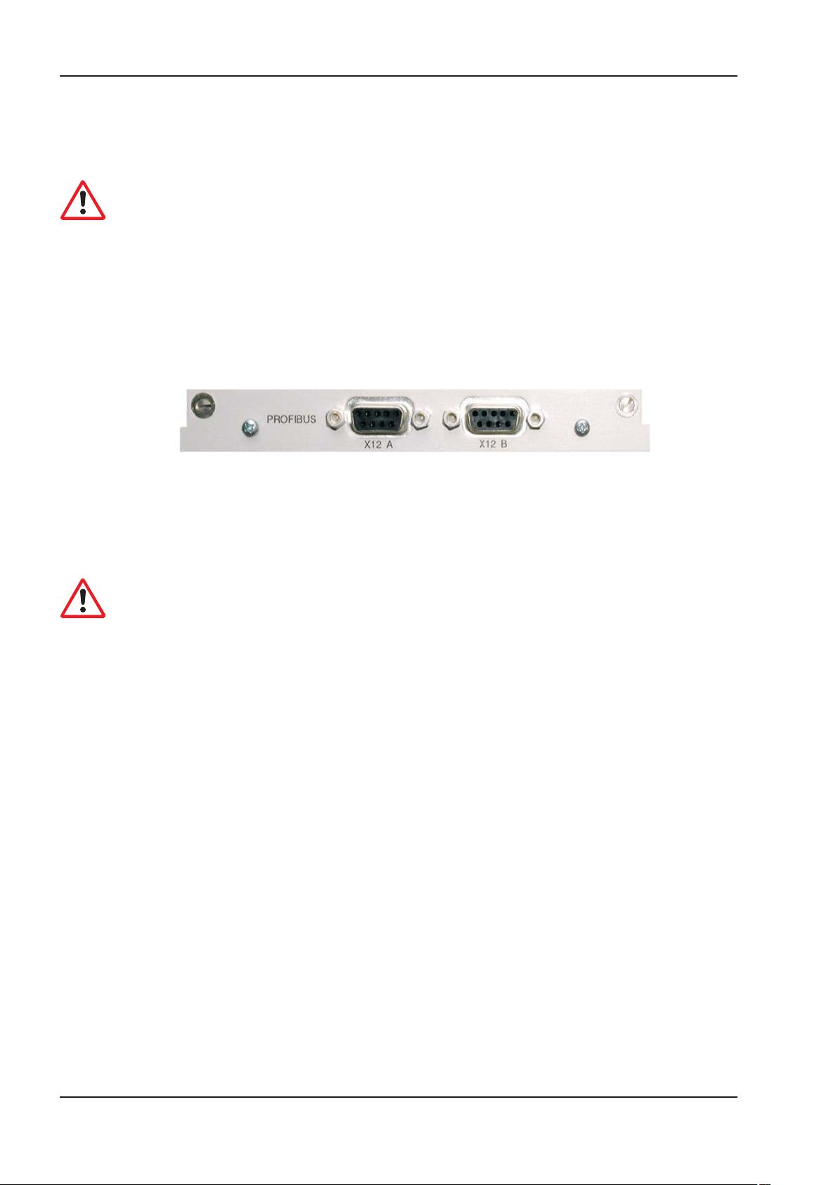
2.1.2.1 Front view
2.1.2.2 Setup of Station Address and Baud Rate
During setup it makes sense to use the keypad on the front panel to preset the station addresses
for the individual amplifiers (see chapter "Setup" in the installation manual).
After changing the station address you must turn the 24V auxiliary supply for the servo
amplifier off and on again for the new address to take affect.
Possible ways for setup:
l
keypad on the front panel of the servo amplifier (see installation manual)
l
setup software: screen page “CAN / Fieldbus”
l
serial interface with a sequence of ASCII commands:
ADDR nn Þ SAVE Þ COLDSTART (with nn = address)
The Baudrate is defined by the hardware configuration in the master controller. Baudrates up to 12
MBaud are possible. During bus initialization, the master controller sends the amplifier the desired
baud rate.
2.1.2.3 Connection technology
Cable selection, cable routing, shielding, bus connector, bus termination and transmission times are
all described in the “Installation guidelines for PROFIBUS-DP/” from PNO, the PROFIBUS User
Organization.
8 PROFIBUS for AX2000/2500
Page 9
BECKHOFF 12/05 Installation / Setup
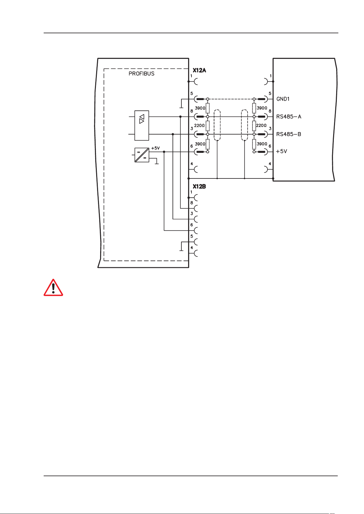
2.1.2.4 Connection diagram
AX2000/2500
With AX2000 terminals AGND and DGND (connector X3) must be joined together !
PROFIBUS for AX2000/2500 9
Page 10
Installation / Setup 12/05 BECKHOFF
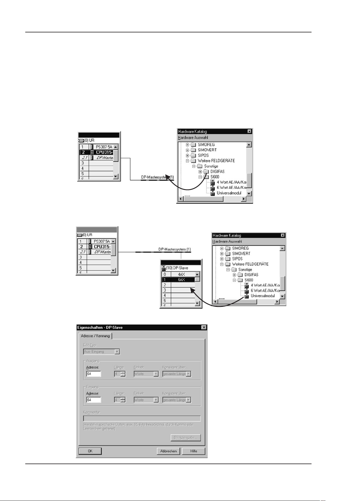
2.1.3 Profibus master module setup
2.1.3.1 Configuration of the master controller ( e.g. Siemens S7)
The graphics interface makes it very easy to configure the Siemens S7 for the PROFIBUS network.
After you have set up the control layout, configure the interface module that is used as follows: Use
our library file KOLL045D.GSD to configure the Profibus master for the servo amplifier. The follo
wing shows a Siemens PLC. Other machine controllers can also be configured for the BECKHOFF
Profibus expansion card. Open the Hardware catalog and drag the symbol for the corresponding
field unit onto the representation of the bus system. A window opens auto- matically for the general
parameterization of the field unit. Enter the address of the participant here.
-
Next, use the same method as above to drag the module from the Hardware catalog into the box for
the field unit, whereby the 4-word module must lie in Cell 0 and the 6-word module in Cell 1.
Another window opens, in which you can set the parameters for the module.
10 PROFIBUS for AX2000/2500
Page 11
BECKHOFF 12/05 Installation / Setup
2.1.4 Standard function block for date exchange with the AX2000/2500
BECKHOFF supplies a S7-function block (FB10) for use Siemens PLC that make it possible to
handle the AX2000/2500 control functions very simply.
This function block and its description can be found as a text file on the CDROM and in the
download section of our website.
2.2 Amplifier setup
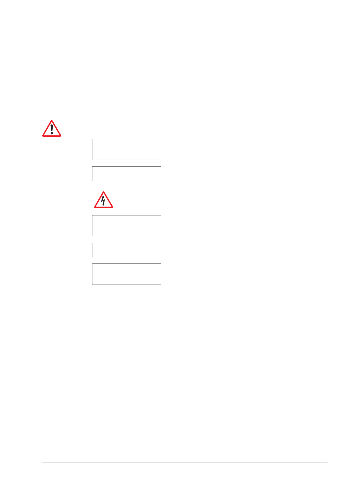
2.2.1 Guide to setup
Only properly qualified personnel with professional expertise in control and drive
technology are permitted to setup the servo amplifier.
Check assembly
+ installation
Connect PC,
start setup software
Setup the
basic functions
Save
parameters
Test the
bus connection
Check that all the safety instructions, which are included in both the
installation manual for the servo amplifier and in this manual, have
been observed and implemented.
Use the setup software for setting the parameters for the servo am
plifier.
Caution!
Make sure that any unintended movement of the drive cannot
create a danger to personnel or machinery.
Now setup the basic functions of the servo amplifier including tuning
the servo loops. This part of setup is described in the setup software
manual and in the online help system of the setup software.
When the optimization is finished, save the controller parameters in
the servo amplifier.
Remove the Enable signal (Terminal X3) and switch off the mains
power supply for the servo amplifier.
The 24V DC auxiliary voltage remains switched on.
Test the installation of the PROFIBUS connection and the interface
to the PROFIBUS master.
Check the PROFIBUS-DP parameter settings and the station confi
guration.
Check the parameter settings for the PROFIBUS interface module.
Check the PLC user program and the parameter settings for the
function block.
-
-
PROFIBUS for AX2000/2500 11
Page 12

Installation / Setup 12/05 BECKHOFF
2.2.2 Important amplifier configuration parameter
The following parameters configure the amplifier for the Profibus interface. They can be set using
the setup software for the amplifier.
EXTWD (PNU 1658)
With this parameter, the observation time (watch dog) for the fieldbus-slot communication can be
set. The observation is only active, if a value higher than 0 is assigned to EXTWD (EXTWD=0,
observation switched off) and the output stage is enabled. If the set time runs out, without the
watchdog-timer being newly triggered by the arrival of a telegram, then the warning n04 (response
monitoring) is generated and the drive is stopped. The amplifier remains ready for operation and the
output stage enabled. Before a new driving command (setpoint) is accepted, this warning must be
deleted (function CLRFAULT or INxMODE=14).
ADDR (PNU 918)
With this command, the node address of the amplifier is set. When the address has been changed,
all parameters should be saved to the EEPROM and the amplifier switched off and on again.
Since the modular structure of the AX2500 as a multi-axis system requires its own addressing,
there is the additional parameter ADDRFB (PNU 2012) for this series, with which a field bus
address different from the internal device address (ADDR) can be defined. As long as ADDRFB =
0, ADDR is the bus address. If ADDRFB > 0, then ADDRFB is the bus address. ADDR is set auto
matically by the AX2500 master module in descending order.
-
AENA (PNU 1606)
With this parameter, the state of the software-enable after switch-on can be defined. The soft
ware-enable allows an external control to enable/disable the output stage. For amplifiers with analog setpoints (OPMODE=1,3) the software-enable is set automatically after switch-on and the devices are ready for operation immediately (if hardware-enable is present). For all others,
software-enable will be set to the value of AENA. The variable AENA also has functionality when
resetting the amplifier after an error (by digital input 1 or the CLRFAULT command). If an error can
be reset by the software, the software-enable is set to the value of AENA after the error is cleared.
In this way the behavior of the amplifier after a software-reset is similar to after the drive is switched
on.
INPT, INPT0 (PNU 1904)
With INPT a delay for the in-position message can be set. With the start of a motion task the
in-position message is deleted and the monitoring of the position is activated after expiration of the
adjusted time. This function is particularly important for positioning procedures within the in-position
window. In this case the in-position message is delayed for a defined time.
-
12 PROFIBUS for AX2000/2500
Page 13
BECKHOFF 12/05 Installation / Setup
2.2.3 Setup Software
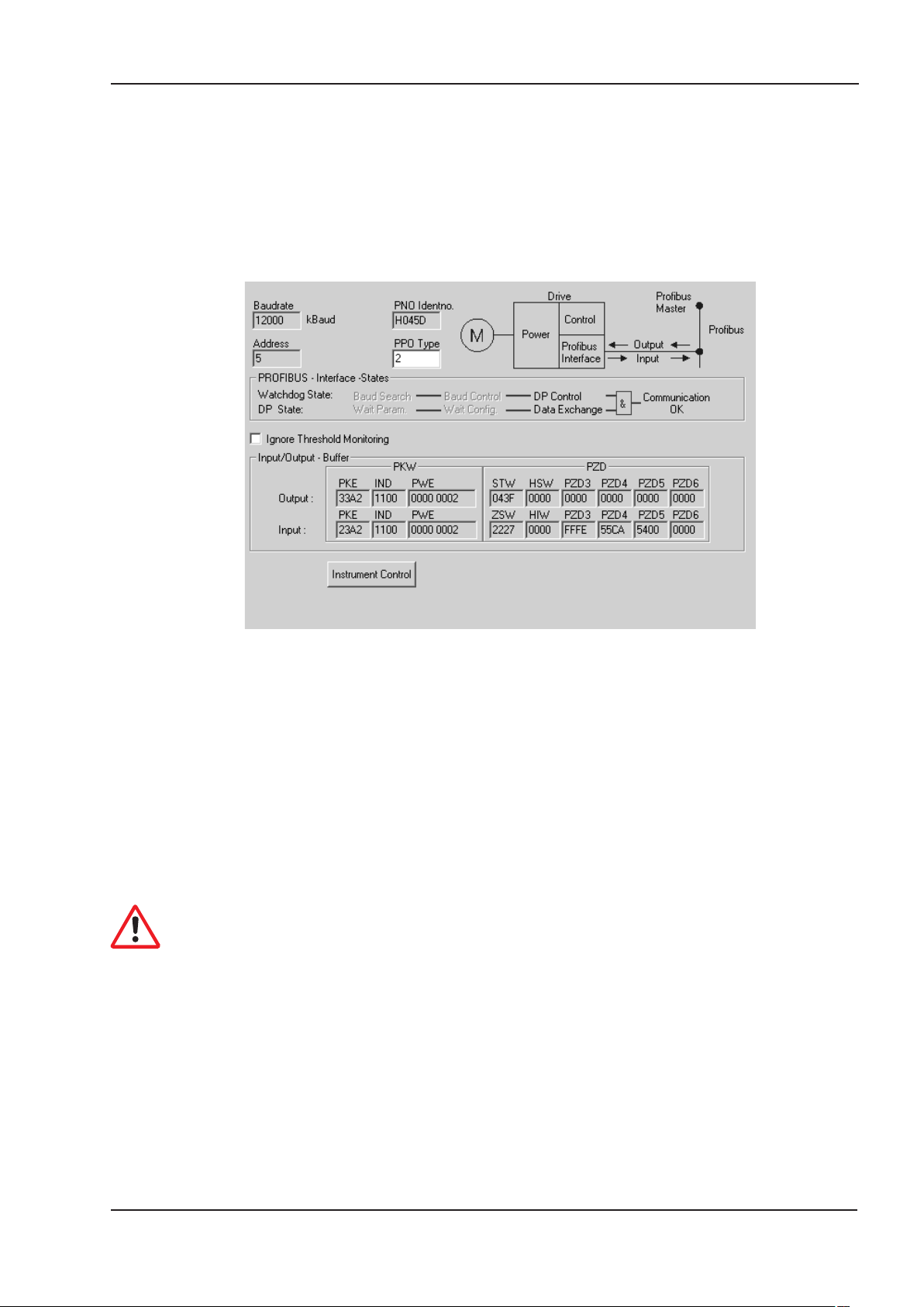
2.2.3.1 Screen page PROFIBUS
This screen will only appear, if the PROFIBUS hardware is built into the servo amplifier. The screen
page displays the PROFIBUS-specific parameters, the bus status, and the data words in the trans
mit and receive directions, as seen by the bus-master. This page is helpful when searching for
errors and commissioning the bus communication.
-
Baudrate: The baud rate set by the PROFIBUS master.
PNO Identno.: The PNO identification is the number for AX2000/2500 from the list
of ID-numbers set by the PROFIBUS user organization.
Address: Station address of the amplifier (setting see p.8).
PPO type: AX2000/2500 only supports PPO-type 2 of the PROFIDRIVE profile.
PROFIBUS Interface states:
Shows the present status of the bus communication. Data can only be
transferred across the PROFIBUS when the “Communication OK”
message is black (not shown in gray).
Input: The last PROFIBUS object received by the master.
Output: The last PROFIBUS object sent by the master.
The data for input/output are only transferred, if the threshold monitoring for the
AX2000/2500 has been activated in the master’s hardware configuration.
PROFIBUS for AX2000/2500 13
Page 14
Installation / Setup 12/05 BECKHOFF
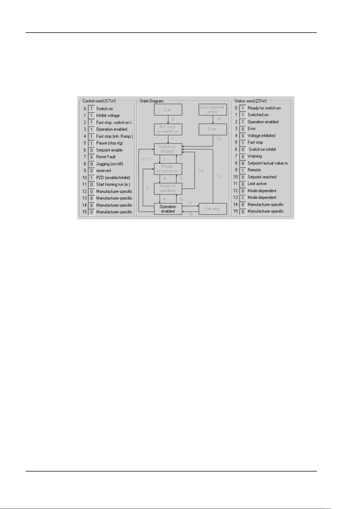
2.2.3.2 Screen page PROFIBUS instrument control
On this screen page the individual bits of the control word (STW) and the status word (ZSW) are
shown. The device status resulting from the status word is visualized in the status machine. The
current status is shown as black, all others are grey. Additionally the previous status is shown by
emphasizing the number of the appropriate arrow.
14 PROFIBUS for AX2000/2500
Page 15
BECKHOFF 12/05 Profile of AX2000/2500
3 Profile of AX2000/2500
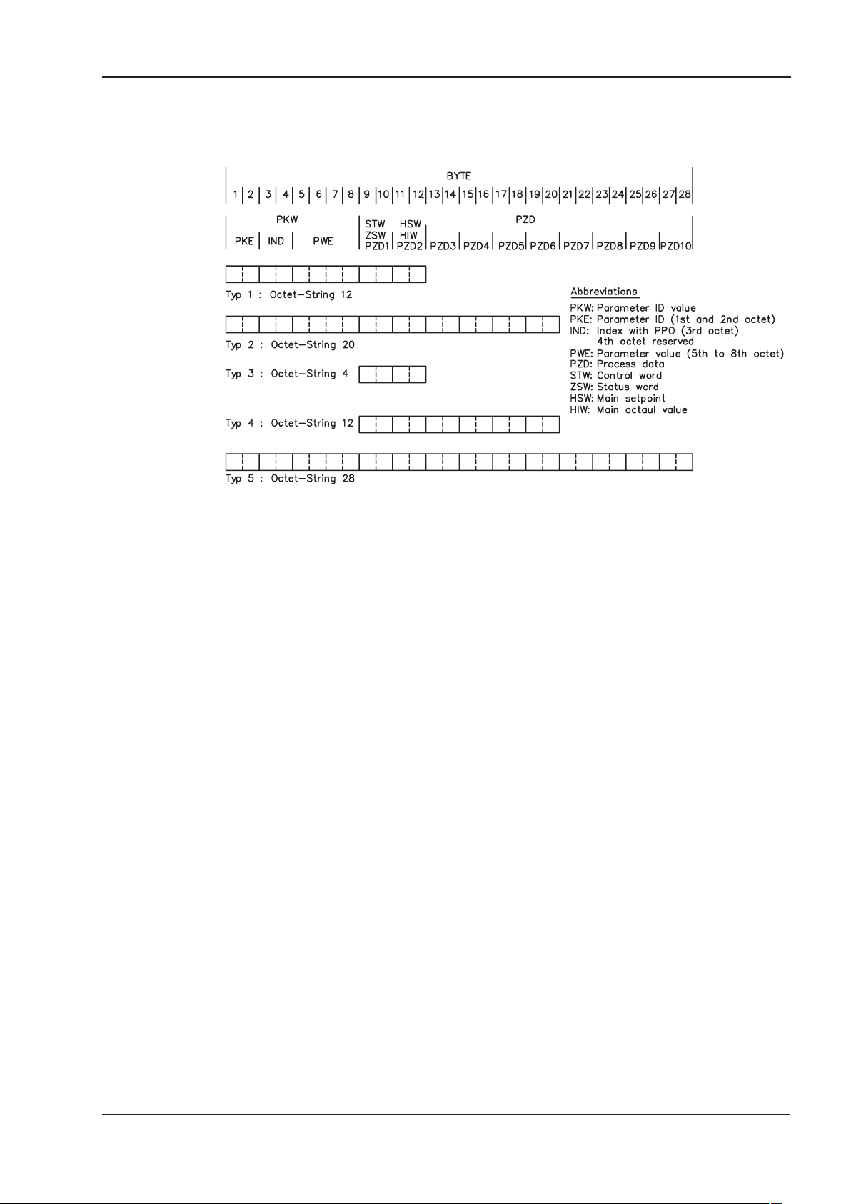
The PROFIBUS-profile PROFIDRIVE includes the following parameter process-data objects (PPO):
AX2000/2500 only uses the PPO-type 2 (with 4 words PKW-section and 6 words PZD-section). The
PKW-section is used mainly for the transmission of parameters for the servo amplifier, the
PZD-section is used principally for handling motion functions.
The telegram can be divided into two sections or data channels:
1. PKW-section (4 words, Bytes 1 to 8)
2. PZD-section (6 words, Bytes 8 to 20)
The PKW data channel can also be termed the service or parameter channel. The service channel
only uses confirmed communication services, and is used by AX2000/2500 as a parameter channel.
This channel has no real-time capability.
The PZD data channel can also be termed the process data channel. The process data channel
uses unconfirmed communication services. The response of the servo amplifier to an unconfirmed
service can only be seen in the reaction of the amplifier (status word, actual values).
This channel has real-time capability.
PROFIBUS for AX2000/2500 15
Page 16
Profile of AX2000/2500 12/05 BECKHOFF
3.1 Parameter channel
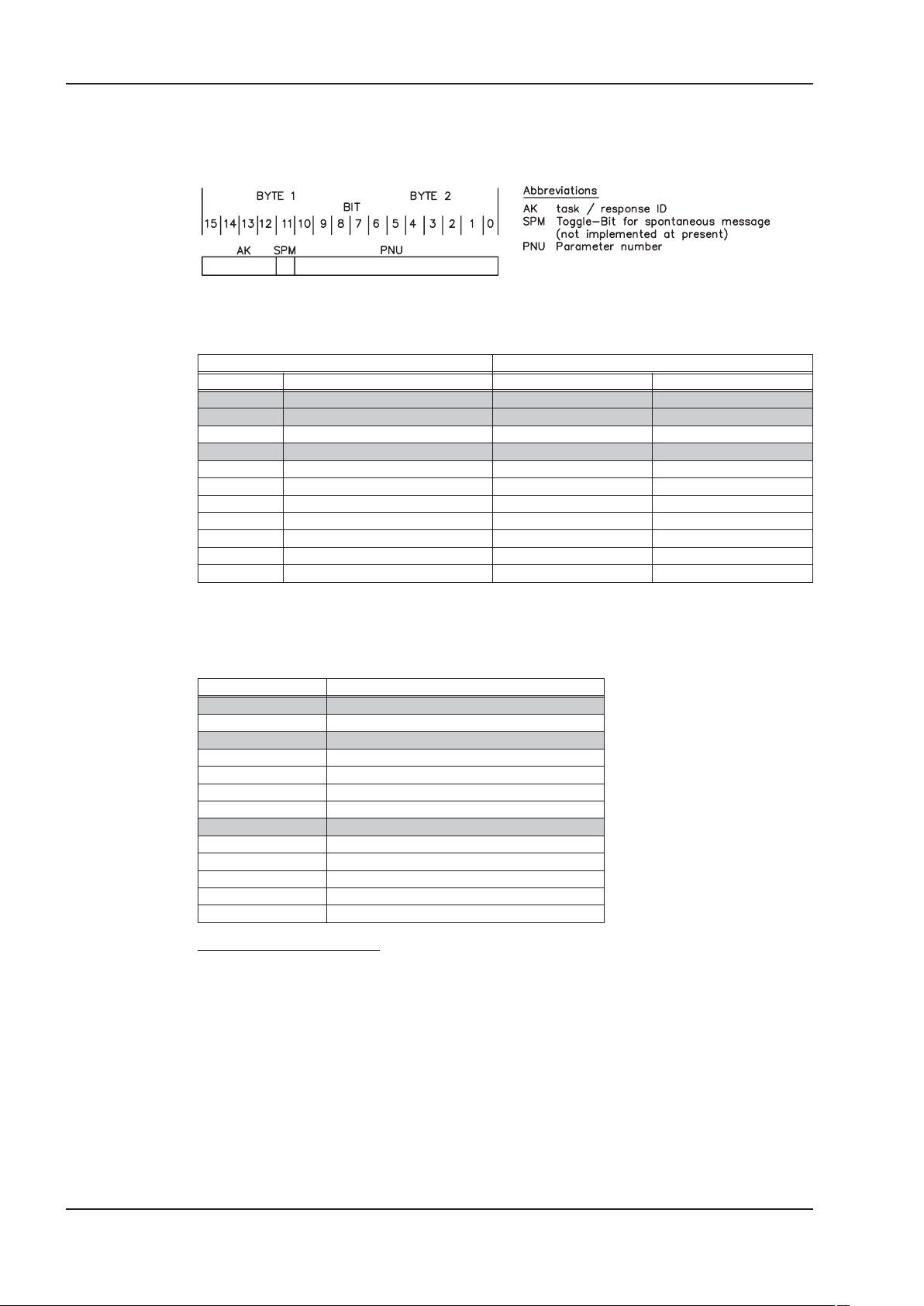
3.1.1 Parameter ID (PKE)
Marked lines in the table are valid for AX2000/2500
Master —> Slave Slave —> Master
Task ID
0 no task 0 0
1 request parameter value 1,2 7
2 alter parameter value [W] 1 7/8
3 alter parameter value [DW] 2 7/8
4 request description element 3 7
5 alter description element 3 7/8
6 request parameter value [A] 4,5 7
7 alter parameter value [A/W] 4 7/8
8 alter parameter value 5 7/8
9 request number of array elements 6 7
10 - 15 reserved
Function
Response ID positive Response ID negative
3.1.1.1 Interpretation of the response IDs
Marked lines in the table are valid for AX2000/2500
Response ID Interpretation
0 no task
1 transmit parameter value
2 transmit parameter value
3 transmit description element
4 transmit parameter value
5 transmit parameter value
6 transmit number of array elements
7 task not possible (with error no.)
8 no operating authority for PKW interface
9 spontaneous message [W]
10 spontaneous message [DW]
11 spontaneous message [A/W]
12 spontaneous message [A/DW]
Abbreviatoins in the tables:
A: Array
W: Word
DW: Double-word
16 PROFIBUS for AX2000/2500
Page 17

BECKHOFF 12/05 Profile of AX2000/2500
3.1.1.2 Response ID 7: Profile specific error numbers
Error no. Description
0
1
2
3
4
5
6
7
8
9
10
11
12
13
14
15
16
17
18
19-100
101
102
103
104
105
106
107
108
109
110
111
112
113
114
115
>115
illegal PNU
parameter value cannot be changed
Lower or upper limit violated
Erroneous sub-index
no array
Incorrect data type
setting not allowed (can only be reset)
Descriptive element cannot be changed
PPO-write, requested in IR, not available
descriptive data not available
access group incorrect
No parameter change rights
Password incorrect
Text cannot be read in cyclic data transmission
Name cannot be read in cyclic data transmission
text array not available
PPO-write missing
task cannot be executed due to operating status
other error
reserved
faulty task ID
software error (command table)
only possible in disabled state
only possible in enabled state
BCC-error in the EEPROM data
only possible after task is stopped
wrong value [16,20]
wrong parameter (OCOPY x [- y] z)
wrong motion block no. (0,1..180,192..255)
wrong parameter (PTEACH x [y])
EEPROM write error
wrong value
BCC-error in motion block
Object is read only or write only
Incompatible object (SDO channel only)
reserve
3.1.2 Index IND
An Index (IND) unequal to 0 is used for reading and writing amplifier parameters
with PNUs > 1600. See page 31 for further description.
PROFIBUS for AX2000/2500 17
Page 18

Profile of AX2000/2500 12/05 BECKHOFF
3.1.3 Parameter value PWE
The data for the PNU-variable is contained in the PWE, and is placed flush right (PKE):
4-byte data (double-word) PWE 5-8 (PWE 8 LSB)
Commands are transferred right justified with task ID 3. If a command cannot be executed, the
response identification AK = 7 signals the error, and an error number is given out. The error num
bers are described on page 17.
-
3.2 The process data channel (PZD)
Cyclical data are exchanged across the PROFIBUS through the process data section of the 20-byte
telegram. Each PROFIBUS cycle triggers an interrupt in the AX2000/2500 and new process data is
exchanged and processed. The interpretation of the PZD by the amplifier depends on the operating
mode that is set. The operating mode is set through a PROFIBUS parameter (PNU 930,
ð p. 23).
In all operating modes, data word 1 of the process data (PZD1) in the direction from control system
to AX2000/2500 is used for instrument control, and in the direction from AX2000/2500 to control
system it has the function of a status indicator for the amplifier.
The interpretation of the process data PZD2 – PZD6 changes depending on the operating mode, as
can be seen in Chapter 5.2.
Caution:
When the AX2000/2500 is switched on, the PROFIDRIVE operating mode that is always set to
–126 (safe state). Before changing the operating mode, bit 10 of the control word STW must
always be set to 0. The new operating mode only becomes active when bit 10 of the control
word is set to 1 (see p. 23).
18 PROFIBUS for AX2000/2500
Page 19

BECKHOFF 12/05 Using the parameter channel (PKW)
4 Using the parameter channel (PKW)
The digital servo amplifiers of the AX2000/2500 series have to be adapted to the circumstances of
your machine. The parameters for the controllers are set using either the setup software or via the
PROFIBUS.
4.1 Read/write an amplifier parameter
Read (AK = 1) or write (AK = 3) amplifier parameters
To read or write an amplifier parameter through PROFIBUS, the corresponding PNU must be used.
The parameters that are written to the AX2000/2500 can be transferred to the non-volatile memory
by using the command “non-volatile parameter save” (PNU 971).
Telegram layout:
Request Response
PKE/AK 1 (read) / 3 (write) 2 (OK) / 7 (error)
PKE/PNU see 4.2.1 as transmitted
PWE
for AK = 3 see p.20ff for data type
for AK = 1 data type irrelevant
for AK = 3 returns the PWE of the request
for AK = 1 see p.20f for data type
4.2 Summary of the parameter numbers
All the parameter numbers (PNUs) for AX2000/2500 are listed in numerical order in the table on
page 20ff, with a short description. The parameter numbers in the range 900 – 999 are profile-spe
cific for the PROFIBUS drive profile PROFIDRIVE. Parameter numbers > 999 are manufacturerspecific.
For better understanding, you can look up the ASCII commands which are in the column “ASCII
command” in the online help the setup software. A description of all ASCII commands can be found
in the ASCII reference lists (referring to the servo amplifier type) located on the product CDROM
and on our website.
Parameter numbers >1600 use the object channel (see p.31ff).
Note!
Some amplifier parameters (e.g. GV) have 2 PNU numbers in the AX2000/2500. Both of them
can be used to read and write the parameter (e.g. PNU 1200 and PNU 1672).
-
PROFIBUS for AX2000/2500 19
Page 20

Using the parameter channel (PKW) 12/05 BECKHOFF
4.2.1 List of the parameters
PNU Data type Access Description
Profile parameter
904 UINT32 ro Number of the supported PPO-write, always 2 - 904
911 UINT32 ro Number of the supported PPO-read, always 2 - 911
918 UINT32 ro Participant address on PROFIBUS ADDR 918
930 UINT32 r/w Selector for operating mode - 930
963 UINT32 ro PROFIBUS baud rate - 963
965 Octet-String2 ro Number of the PROFIDRIVE profile (0302H) - 965
970 UINT32 wo Load default parameter set RSTVAR 970
971 UINT32 wo non-volatile parameter save SAVE 971
Manufacturer-specific parameters
General parameters
1000 Visible String4 ro Instrument ID - 1000
1001 UINT32 ro Manufacturer-specific error register ERRCODE 1001
1002 UINT32 ro Manufacturer-specific status register - 1002
Speed controller parameters
1672 UINT32 r/w Kp – gain factor for speed controller GV 1200
1677 UINT32 r/w Tn – integral-action time for speed controller GVTN 1201
1676 UINT32 r/w PID – T2 – time constant for speed controller GVT2 1202
1601 UINT32 r/w Setpoint ramp+, speed controller ACC 1203
1634 UINT32 r/w Setpoint ramp-, speed controller DEC 1204
1637 UINT32 r/w Emergency stop ramp, speed controller DECSTOP 1205
1890 UINT32 r/w Maximum speed VLIM 1206
1895 UINT32 r/w Overspeed VOSPD 1207
1642 UINT32 r/w Count direction DIR 1208
Position controller parameters
1894 UINT32 r/w Velocity multiplier for jogging/homing VMUL 1250
1807 UINT32 r/w Axis type POSCNFG 1251
1798 INTEGER32 r/w InPosition window PEINPOS 1252
1799 INTEGER32 r/w Following error window PEMAX 1253
1860 INTEGER32 r/w Position register 1 SWE1 1254
1862 INTEGER32 r/w Position register 2 SWE2 1255
1864 INTEGER32 r/w Position register 3 SWE3 1256
1866 INTEGER32 r/w Position register 4 SWE4 1257
1803 UINT32 r/w Denominator resolution PGEARO 1258
1802 UINT32 r/w Numerator resolution PGEARI 1259
1814 UINT32 r/w Minimum acceleration/braking time PTMIN 1260
1669 UINT32 r/w Feed-forward factor for position controller GPFFV 1261
1666 UINT32 r/w KV - factor for position controller GP 1262
1671 UINT32 r/w KP - factor for position controller GPV 1263
1670 UINT32 r/w Tn - integral-action time for position controller GPTN 1264
1816 UINT32 r/w Maximum velocity for positioning mode PVMAX 1265
1856 UINT32 r/w Configuration variable for software switch SWCNFG 1266
Position data for the position control mode
1790 INTEGER32 r/w Position O_P 1300
1791 INTEGER16 r/w Velocity O_V 1301
1785 UINT32 r/w Motion task type O_C 1302
1783 INTEGER16 r/w Starting time (acceleration) O_ACC1 1304
1786 INTEGER16 r/w Braking time (deceleration) O_DEC1 1305
1784 INTEGER16 r/w Jolt limiting (acceleration) O_ACC2 1306
1787 INTEGER16 r/w Jolt limiting (deceleration) O_DEC2 1307
1788 UINT32 r/w Number of next motion task O_FN 1308
1789 UINT32 r/w Start delay for next motion task O_FT 1309
1310 2 * UINT16 wo Copy a motion task OCOPY 1310
1311 special r/w Position, 32 bit floating decimal point format 1311
1312 special r/w Velocity, 32 bit floating decimal point format 1312
1857 UINT32 r/w Configuration variable 2 for software switch SWCNFG2 1267
ASCII com
-
mand
PNU (old)
20 PROFIBUS for AX2000/2500
Page 21

BECKHOFF 12/05 Using the parameter channel (PKW)
PNU Data type Access Description
Position set-up mode
1773 UINT32 r/w Homing type NREF 1350
1644 UINT32 r/w Homing direction DREF 1351
1602 UINT32 r/w Acceleration ramp (jogging/homing) ACCR 1352
1636 UINT32 r/w Braking ramp DECR 1353
1831 UINT32 r/w Reference offset ROFFS 1354
1896 UINT32 ro Homing run velocity VREF 1355
1889 UINT32 ro Jogging velocity VJOG 1356
Actual values
1400 INTEGER32 ro Actual position 20 bits/turn PRD 1400
1401 INTEGER32 ro Speed 1401
1402 INTEGER32 ro Incremental position, actual value 1402
1800 INTEGER32 ro SI-position, actual value PFB 1403
1815 INTEGER32 ro SI-velocity, actual value PV 1404
1797 INTEGER32 ro SI following error PE 1405
1688 INTEGER32 ro RMS current I 1406
1880 INTEGER32 ro SI-speed, actual value V 1407
1873 INTEGER32 ro Heatsink temperature TEMPH 1408
1872 INTEGER32 ro Internal temperature TEMPE 1409
1882 INTEGER32 ro DC-bus (DC-link) voltage VBUS 1410
1792 INTEGER32 ro Regen power PBAL 1411
1689 INTEGER32 ro I2t - loading I2T 1412
1876 INTEGER32 ro Running time TRUN 1413
1414 special ro Position, 32 bit floating decimal point format 1414
1415 special ro Velocity, 32 bit floating decimal point format 1415
Digital I/O configuration
1698 UINT32 r/w Function of digital input 1 IN1MODE 1450
1701 UINT32 r/w Function of digital input 2 IN2MODE 1451
1704 UINT32 r/w Function of digital input 3 IN3MODE 1452
1707 UINT32 r/w Function of digital input 4 IN4MODE 1453
1699 INTEGER32 r/w Auxiliary variable for digital input 1 IN1TRIG 1454
1702 INTEGER32 r/w Auxiliary variable for digital input 2 IN2TRIG 1455
1705 INTEGER32 r/w Auxiliary variable for digital input 3 IN3TRIG 1456
1708 INTEGER32 r/w Auxiliary variable for digital input 4 IN4TRIG 1457
1775 INTEGER32 r/w Function of digital input 1 O1MODE 1458
1778 INTEGER32 r/w Function of digital input 2 O2MODE 1459
1776 UINT32 r/w Auxiliary variable for digital output 1 O1TRIG 1460
1779 UINT32 r/w Auxiliary variable for digital output 2 O2TRIG 1461
1852 UINT32 r/w
Analog configuration
1607 UINT32 r/w Configuration of the analog input functions ANCNFG 1500
1613 UINT32 r/w Configuration monitor function analog output 1 ANOUT1 1501
1611 UINT32 r/w Offset voltage for analog input 1 ANOFF1 1502
1617 UINT32 r/w Filter time constant for analog input 1 AVZ1 1503
1897 UINT32 r/w Scaling factor for velocity, analog input 1 VSCALE1 1504
1713 UINT32 r/w Scaling factor for current, analog input 1 ISCALE1 1505
1614 UINT32 r/w Configuration monitor function analog output 2 ANOUT2 1506
1612 UINT32 r/w Offset voltage for analog input 2 ANOFF2 1507
1898 UINT32 r/w Scaling factor for velocity, analog input 2 VSCALE2 1508
1714 UINT32 r/w Scaling factor for current, analog input 2 ISCALE2 1509
Motor parameters
1735 UINT32 r/w Brake configuration MBRAKE 1550
1753 UINT32 r/w Motor number from motor database MNUMBER 1551
Manufacturer specific object channel
³1600 Þ p. 31 and description of the ASCII-commands on the CDROM or in the online help. ³1600
State of 4 digital inputs, Enable,
2 digital outputs
ASCII com
STATIO 1462
mand
-
PNU (old)
Abbreviations in the “Access” column
Abbrev. Description
wo “write only” access
ro “read only” access
r/w read and write access
PROFIBUS for AX2000/2500 21
Page 22

Using the parameter channel (PKW) 12/05 BECKHOFF
4.2.2 Standard PROFIDRIVE parameters
4.2.2.1 PNU 940/911: PPO type write/read
These parameters describe the numbers of the supported PPO-types write und read.
Since only PPO-type 2 is supported (see Chapter 3), this parameter is always set to 2.
4.2.2.2 PNU 918: PROFIBUS node address
With this parameter the PROFIBUS - node address of the amplifier can be read.
AX2000/2500
The range of addresses can be extended from 1..63 to 1..127 with the ASCII-command MDRV.
Setting up the station address, see page 8.
4.2.2.3 PNU 963: baud rate
This parameter defines the index of the baud rate that is used for PROFIBUS communication, and
can only be read. The baud rate is given out by the PROFIBUS-master.
The table below shows the indices with the according baud rates (in kBaud):
Index 0 123456789
Baud rate
12000 6000 3000 1500 500 187.5 93.75 45.45 19.2 9.6
4.2.2.4 PNU 965: PROFIDRIVE profile number
This parameter can be used to read out the number of the PROFIDRIVE profile. Profile Number 3,
Version 2 is used.
4.2.2.5 PNU 970: default parameters
With this parameter you can reject all the parameters that are set and load the manufacturer’s
default values.
4.2.2.6 PNU 971: non volatile saving of parameters
With this parameter you can save all the parameter settings to the EEPROM. To do this, the para
meter must have the value PWE = 1 when the transfer takes place.
-
22 PROFIBUS for AX2000/2500
Page 23

BECKHOFF 12/05 Using the parameter channel (PKW)
4.2.2.7 PNU 930: Selection Switch for Operating Mode
The “Selector for operating modes” is defined by the drive profile, and mirrors the operating modes
of the drive profile to the operating modes of the AX2000/2500. The following table shows a sum
mary of the operating modes:
If process data are exchanged across the PROFIBUS, then the operating modes of the drive
profile must only be selected with PNU 930.
-
Operating
mode of
drive profile
2 8 Positioning mode according to PROFIDRIVE profile
1 0 Digital speed control according to PROFIDRIVE profile
0 - reserved
-1 1 Speed control, analog setpoint
-2 2 Torque control, digital setpoint
-3 3 Torque control, analog setpoint
-4 4 Position control, electronic gearing
-5 5 Position control, external trajectory
-6 to -15 - reserved
-16 - ASCII channel for expanded parameterization
-17 to -125 - reserved
-126 - Initial settings when amplifier is switched on
Operating mode AX2000/2500
(ASCII command “OPMODE”)
Description
The individual operating modes are described in chapter 5.2. A change of operating mode can only
be undertaken in connection with the control word.
The operating mode must be changed according to the following sequence:
1. Inhibit setpoints and process data
Bit 10 in the control word is set to 0, so that no new setpoints will be accepted by the
servo amplifier and no new control functions can be initiated. A new operating mode
can, however, be selected while a motion function is being performed.
The control word is only inhibited to the extent that the servo amplifier can always be
switched into a safe state.
2. Select the new operating mode with PNU 930
The new operating mode is selected with parameter 930 through the parameter channel,
but not yet accepted.
3. Set/receive the setpoints and actual values
Enter the corresponding setpoints in the setpoint area of the process data.
Here you must take note that the normalization and data formats depend on the operating
mode that is selected. The interpretation of the actual values is also altered
(see Þ p. 15 and p. 37ff). The user program must respond accordingly.
4. Enable the setpoints
Bit 10 of STW is set to 1. The setpoints are immediately accepted and processed.
The new actual values are output with the appropriate normalization and data format.
After switch-on or after a coldstart the servo amplifier is always in the safe operating mode.
In the safe operating mode (-126), no motion functions can be initiated via the PROFIBUS.
However, it is possible to perform motion functions with the the setup Software.
If the operating mode is changed, then motion functions can only be operated via the
PROFIBUS. If the operating mode is changed via another communication channel, then the
amplifier is emergency braked and the error F21 (Handling error, expansion card) is
signaled.
PROFIBUS for AX2000/2500 23
Page 24

Using the parameter channel (PKW) 12/05 BECKHOFF
4.2.3 Manufacturer specific parameters
4.2.3.1 PNU 1000: instrument ID
The instrument ID consists of four ASCII characters, with the contents “Sxyz”.
- x stands for the servoamplifier family
- yz stands for the current level of the output stage
4.2.3.2 PNU 1001: manufacturer specific error register
The assignment of the error register can be seen in the following table. The explanation of the indi
vidual errors can be found in the assembly & installation instructions for the servo amplifier.
Bit Description
0 Error F01: Heatsink temperature
1 Error F02: Overvoltage
2 Error F03: Following error
3 Error F04*: Feedback
4 Error F05: Undervoltage
5 Error F06*: Motor temperature
6 Error F07*: Auxiliary voltage
7 Error F08: Overspeed
8 Error F09*: EEPROM
9 Error F10*: Flash-EEPROM
10 Error F11*: Mechanical holding brake
11 Error F12*: Motor phase
12 Error F13: Internal temperature
13 Error F14*: Output stage
14 Error F15: I²t max.
15 Error F16: Mains supply-BTB
16 Error F17*: A/D-converter
17 Error F18*: Regen circuit
18 Error F19: Mains supply phase
19 Error F20*: Expansion card error
20 Error F21*: Handling error, plug-in card
21 Error F22: Earth short
22 Error F23: CAN-Bus off
23 Error F24: Warning
24 Error F25: Commuation error
25 Error F26: Limit switch
26 Error F27: AS functionality
27-30 Error F28 - F31*: reserved
31 Error F32*: System error
When the cause of the error has been cleared, the error state can be canceled by setting Bit 7 in
the control word (STW).
The error response of the AX2000/2500 to the reset will differ, depending on the error that has
occurred:
For errors that are marked by an asterisk (*), setting the reset bit initiates a cold-start of the ampli
fier, whereby the PROFIBUS communication to this amplifier will also be interrupted for several
seconds. Depending on the circumstances, this break in communication may have to be separately
handled by the PLC.
For the other errors, the reset leads to a warm start, during which the communication will not be
interrupted.
-
A description of the individual errors and recommendations for removing them can be found in the
amplifier's installation manual.
24 PROFIBUS for AX2000/2500
Page 25

BECKHOFF 12/05 Using the parameter channel (PKW)
4.2.3.3 PNU 1002: manufacturer specific status register
The bit assignment can be seen in the following table:
Bit Description
0 Warning 1: I²t threshold exceeded (set, as long as I
1 Warning 2: Regen power exceeded (set, as long as the set regen power is exceeded)
2 Warning 3: Following error
3 Warning 4: Threshold monitoring (field bus) active
4 Warning 5: Mains supply phase missing
5 Warning 6: Software limit-switch 1 has been activated
6 Warning 7: Software limit-switch 2 has been activated
7 Warning 8: Faulty motion task has been started
8 Warning 9: No reference point was set at the start of the motion task
9 Warning 10: PSTOP active
10 Warning 11: NSTOP active
11 Warning 12: Motor default values were loaded (HIPERFACE
12 Warning 13: Expansion card is not working properly
13 Warning 14: Sine encoder commutation not carried out
14 Warning 15: Speed - current table error INxMODE 35
15 Warning 16: Reserve
Motion task active (is set as long as a position control task is active - motion task, jogging, homing).
16
Reference point set (is set after a homing run, or when an absolute position (multi-turn) encoder is used.
17
This is canceled when the amplifier is switched on, or when a homing run is started.
Actual position = home position (is set as long as the reference switch is activated).
18
InPosition (is set as long as the difference between the target position for a motion task and the actual
position is smaller than PEINPOS. The InPosition signal is suppressed if a following task is started at
19
the target position.
Position latch set (positive edge) – this is set if a rising edge is detected on the INPUT2 (IN2MODE=26)
20
that is configured as a latch. This is canceled if the latched position is read out (LATCH16/LATCH32)
—
21
Position 1 reached (is set if the configured condition for this signal (SWCNFG, SWE1, SWE1N) is met.
Depending on the configuration, this bit is set on exceeding SWE1, or going below SWE1, on reaching
22
the InPosition window SWE1...SWE1N or on leaving the InPosition window SWE1...SWE1N.
Position 2 reached (see above)
23
Position 3 reached (see above)
24
Position 4 reached (see above)
25
Initialization completed (is set if the internal initialization of the amplifier is completed).
26
—
27
Speed = 0 (is set as long as the motor speed is below the standstill threshold VEL0).
28
Safety relay has been triggered (is set as long as the safety relay is open AS)
29
Output stage enabled (is set when software and hardware enables are set).
30
Error present (is canceled when the amplifier is switched on, or if the function “Cancel error” is called.
31
In the process data, Bits 16 to 31 of the manufacturer-specific status register are given out.
Warnings 3 and 4 can be reset through Bit 13 in the control word.
is above the threshold)
rms
®
or EnDat®feedback)
PROFIBUS for AX2000/2500 25
Page 26

Using the parameter channel (PKW) 12/05 BECKHOFF
4.2.4 Position control parameters
4.2.4.1 PNU 1894: velocity multiplier
This parameter is used to enter a multiplier for the jogging/homing velocity. In Positioning opmode,
the velocity for jogging/homing is set through PZD2 jogging/homing is started using bit 8/ bit 11 in
the control word (STW).
The actual jog velocity is calculated according to the following formula:
V Bit V Bit velocity multipli
() ()32 16
Jog vel Jog PZD,. ,
=´er Bit()16
2
The default value for PNU 1894 is 1.
4.2.4.2 PNU 1807: axis type
This parameter is used to define the axis type.
Value AX2500 AX2000
0 Linear axis Linear axis
1 Rotary axis Rotary axis
2 Modulo axis Modulo axis
4.2.5 Position data for the position control mode
4.2.5.1 PNU 1790: position
Since the AX2000/2500 calculates all positioning operations internally only on an incremental basis,
there are limitations on the usable range of values for distances that are given in SI (user) units.
The range for the incremental position covers the values from -2
The resolution that is determined by the PGEARO (PNU1803 ind1) and PGEARI (PNU1802 ind1)
parameters and the variable PRBASE fix the sensibly usable range for positioning operations.
The variable PRBASE determines, through the equation
motor turn. The value of PRBASE can only be 16 or 20.
PGEARO contains the number of increments that must be traversed when the distance to be
moved is PGEARI. The default values for PGEARO correspond to one turn.
The number of turns that can be covered are given as follows:
-2048..+2047 for PRBASE=16 and -32768..+32767 for PRBASE=20
The sensibly usable position range is derived as follows:
PGEARI
31 31
--221
* ...( )*
PGEARO
31 31
...( )
--221
4.2.5.2 PNU 1791: velocity
The usable range for the velocity is not limited by the available data area. It is limited by the maxi
mum applicable speed nmax, which is given by the speed parameter VLIM as the final limit speed
for the motor.
The maximum velocity is thus given by:
n
=´ ´2
SI
,max max
n
PGEARI
PGEARO
PGEARI
PGEARO
PRBASE
31
to (231-1).
PRBASE
n
= 2
, the number of increments per
for PGEARI <= PGEARO or
for PGEARI > PGEARO
with n
in turns/second
max
-
or, in incremental units, as:
250
m
incr
. max. max
=´ ´ = ´2
vn
PRBASE PRBASE
sn
max
sec
1 4000
2
with n
in turns/second
max
26 PROFIBUS for AX2000/2500
Page 27

BECKHOFF 12/05 Using the parameter channel (PKW)
4.2.5.3 PNU 1785: motion task type
Bit Value Meaning
The position value that is given is evaluated as an absolute position.
0
0
1
2
3
4
5
6
7
8
9
10
11
12
13
14
15 -
The position value that is given is evaluated as a relative traversing distance.
1
The two following bits then determine the type of relative motion.
If Bit 1and Bit 2 are set to 0 and Bit 0 set to 1, then the relative motion task is performed
0
according to the “InPosition” bit.
The new target position is given by the old target position plus the traversing distance.
1
Bit 1 has priority over Bit 2.
If Bit 1and Bit 2 are set to 0 and Bit 0 set to 1, then the relative motion task is performed
0
according to the “InPosition” bit.
The new target position is given by the actual position plus the traversing distance.
1
no following task available
0
There is a following task, but it must be defined through parameter O_FN, PNU 1788
1
Change over to next motion task, with braking to 0 at the target position.
0
Change over to next motion task, without standstill at the target position.
1
The type of velocity transition is determined by Bit 8.
Change over to next motion task, without evaluating inputs.
0
A following motion task is started by a correspondingly configured input.
1
Start the next motion task by Input State = low or if bit 7 = 1after the delay set in
0
PNU 1789.
Start the next motion task by Input State = high or if bit 7 = 1after the delay set in
1
PNU 1789.
The next motion task is started immediately.
0
The next motion task is started after the delay time set by PNU 1789 or, if Bit6=1,previ
1
ously by a corresponding input signal.
Only for following motion tasks and Bit4=1:from the target position for the previous moti-
0
on task onwards, the velocity is altered to the value for the following motion task.
The change of velocity is made so that the velocity at the target position of the previous
1
motion task matches the value given for the following motion task.
reserved
-
Accelerations are calculated according to the run-up/acceleration and run-down/braking ti-
0
mes for the motion task.
the deceleration/aceleration ramps are interpreted in mm/s²
1
The target position and target velocity of a motion task are interpreted as increments.
0
The target position and target velocity are recalculated as increments before the start of
1
the motion task. The parameters PGEARI and PGEARO are used for this purpose.
The programmed velocity is used as the velocity for the motion task.
0
The velocity for the motion task is determined by the voltage present on analog input 1at
1
the start of the motion task.
reserved
-
4.2.5.4 PNU 1783: acceleration time
This parameter defines the total time or rate (depending on the type of units selected for acceler
ation) to reach the target velocity for the motion task.
-
4.2.5.5 PNU 1784: acceleration jolt limiting
This parameter defines the form of the acceleration ramp.
If a value ¹ 0 is entered here, then a sin²-ramp (S-curve) is used to reach the target velocity.
To employ sine²-ramps, the configuration variable SPSET has to be set to 2 (via the ASCII-channel
or the ASCII-terminal in the setup software) and to be saved.
PROFIBUS for AX2000/2500 27
Page 28

Using the parameter channel (PKW) 12/05 BECKHOFF
4.2.5.6 PNU 1786: deceleration time
This parameter defines the total time or rate (depending on the type of units selected for deceler
ation) to reduce the velocity to 0 at the target position.
4.2.5.7 PNU 1787: deceleration jolt limiting
This parameter defines the form of the braking/deceleration ramp.
If a value ¹ 0 is entered here, then a sin²-ramp (S-curve) is used for braking/deceleration.
4.2.5.8 PNU 1788: next motion task
The motion task number of the motion task to be started can be from 1 to 180 (motion tasks in
EEPROM) or 192 to 255 (motion tasks in RAM).
4.2.5.9 PNU 1789: start delay
This parameter is used to set a delay time before the start of a motion task.
4.2.5.10 PNU 1310: copy motion task
This parameter can be used to copy motion tasks. The source motion task must be entered in the
high-value portion of PWE (PZD5&6)andthetarget motion task must be entered in the low-value
portion of PWE (PZD 7 & 8).
4.2.5.11 PNU 1311: position, 32 bit floating decimal point format
-
With this object the target position for motion task 0 (direct motion task, see ASCII – command
O_P) can be set in 32 Bit Floating decimal point format (IEEE).
Right of decimal point positions will be truncated. This objekt is, aside from the data format, identical PNU 1790. The defaults are indicated in micrometers.
Use:
Controls that support only 16 Bit integer and 32 Bit floating decimal point.
4.2.5.12 PNU 1312: velocity, 32 bit floating decimal point format
With this object the velocity for motion task 0 (direct motion task, see ASCII – command O_V) can
be set in 32 Bit Floating decimal point format (IEEE).
Right of decimal point positions will be truncated. This objekt is, aside from the data format, identi
cal PNU 1791.
Use:
Controls that support only 16 Bit integer and 32 Bit floating decimal point.
-
28 PROFIBUS for AX2000/2500
Page 29

BECKHOFF 12/05 Using the parameter channel (PKW)
4.2.6 Setup mode: position
4.2.6.1 PNU 1773: homing type
This parameter can be used to determine which type of homing run should be applied. The
assignment can be seen in the following table:
PWE Type of homing run
Reference point at the present position
0
Initiator with resolver zero mark
1
Hardware limit-switch resolver zero mark
2
Initiator without resolver zero mark
3
Hardware limit-switch without resolver zero mark
4
Zero mark / feedback unit
5
Reference point at the actual position
6
Hardware limit-switch with resolver zero mark
7
Absolute SSI-position
8
Move to Mechanical Stop
9
4.2.6.2 PNU 1644: homing direction
This parameter can be used to determine the direction of motion for homing runs. If set equal 0,
then the direction of motion is negative; for a value 1 it is positive, and fora2itdepends on the dis
tance to the reference point in the direction in which the homing run started.
-
4.2.7 Actual values
4.2.7.1 PNU 1401: speed
The parameter value is the actual speed of the motor in increments / 250 µsec, which are the
amplifier’s internal units.
4.2.7.2 PNU 1402: incremental position, actual value
The parameter value is the actual position value in increments.
4.2.7.3 PNU 1800: actual position value in SI (User) units
The parameter value is the actual SI (user unit) position value.
4.2.7.4 PNU 1414: actual position, 32 bit floating decimal point format
With this object the actual position (see ASCII-command PFB) can be read in a 32 Bit Floating deci
mal point format (IEEE).
Right of decimal point positions will be truncated. This object is, aside from the data format, identi
cal to PNU1800.
Use:
PLC Controls that support only 16 Bit integer and 32 Bit floating decimal point.
-
-
PROFIBUS for AX2000/2500 29
Page 30

Using the parameter channel (PKW) 12/05 BECKHOFF
4.2.7.5 PNU 1415: actual velocity, 32 bit floating decimal point format
With this object the actual velocity (see ASCII-command PV) can be read in a 32 Bit Floating deci
mal point format (IEEE).
Right of decimal point positions will be truncated. This object is, aside from the data format, identi
cal to PNU1815.
Use:
PLC Controls that support only 16 Bit integer and 32 Bit floating decimal point.
4.2.8 Digital I/O configuration
All settings for the digital inputs and outputs only become effective after being saved in the
EEPROM and then switching off and on again, or making a cold start of the AX2000/2500. Details
on each configuration setting can be seen in the user manual for the setup software.
4.2.8.1 PNUs 1698/1701/1704/1707: digital input configuration
This parameter can be used to configure the digital inputs 1 to 4 individually.
The configurable functions depend on the used amplifier and are described in the ASCII Object
Reference.
4.2.8.2 PNUs 1775/1778: digital output configuration
These parameters can be used to configure the two digital outputs individually. The configurable
functions depend on the used amplifier and are described in the ASCII Object Reference.
-
-
4.2.9 Analog configuration
All settings for the analog inputs and outputs only become effective after being saved in the
EEPROM and then switching off and on again, or making a cold start of the AX2000/2500. The significance of the functions can be seen in the user manual for the setup Software.
4.2.9.1 PNU 1607: analog input configuration
This parameter can be used to configure the two analog inputs together. The configurable functions
depend on the used amplifier and are described in the ASCII Object Reference.
4.2.9.2 PNU 1613/1614: analog output configuration
This parameter can be used to configure the two analog outputs individually.
PWE Function
Off
0
n act
1
I act
2
n setp
3
I setp
4
S_fault
5
Slot
6
30 PROFIBUS for AX2000/2500
Page 31

BECKHOFF 12/05 Using the parameter channel (PKW)
4.2.10 Manufacturer specific object channel (from PNU 1600)
With PNUs>1600 you can programm each ASCII-parameter/command of the AX2000/2500. The
PNU can be calculated by the object number with a specific offset (ASCII command reference list:
DPR).
All PNUs described in this manual can be reached with index=1. In the ASCII reference list you find
for every parameter the PNU and the referring index. More functions of the object channel can be
used with the indices listed below.
The offset and the indices that must be used depend on the object number:
Objekt number Offset PNUs Index
0 ...447 1600 1600 ...2047 00h ...08h (1 ... 8dez)
448 ...847 1200 1648 ...2047 10h ...18h (16 ... 24dez)
848 ...1047 800 1648 ...2047 20h ...28h (32 ...40dez)
Index 0/10h/ 20h depending on the object no. (see above)
short description Number of entries
Unit —
Access —
Data type UNSIGNED8
Value range 0 ... 2
EEPROM —
8
-1
Index 1/11h/ 21h depending on the object no. (see above)
short description read/write a parameter
Unit see corresponding ASCII-command
Access see corresponding ASCII-command
Data type see corresponding ASCII-command
Value range see corresponding ASCII-command
Default value —
EEPROM see corresponding ASCII-command
Index 2/12h/ 22h depending on the object no. (see above)
short description read lower limit
Unit see corresponding ASCII-command
Access Read only
Data type see corresponding ASCII-command
Value range see corresponding ASCII-command
Default value —
EEPROM —
Index 3/13h/ 23h depending on the object no. (see above)
short description read upper limit
Unit see corresponding ASCII-command
Access Read only
Data type see corresponding ASCII-command
Value range see corresponding ASCII-command
Default value —
EEPROM —
Index 4/14h/ 24h depending on the object no. (see above)
short description read default value
Unit see corresponding ASCII-command
Access Read only
Data type see corresponding ASCII-command
Value range see corresponding ASCII-command
Default value —
EEPROM —
PROFIBUS for AX2000/2500 31
Page 32

Using the parameter channel (PKW) 12/05 BECKHOFF
Index 5/15h/ 25h depending on the object no. (see above)
short description read object format
Unit —
Access Read only
Data type see corresponding ASCII-command
Value range see corresponding ASCII-command
Default value —
EEPROM —
Desription:
The following object formats are possible:
0 Function (no parameters – write only)
1 Function (32-Bit parameter)
2 Function (32-Bit parameter with weighting 3)
3 8-Bit integer
4 8-Bit unsigned integer
5 16-Bit integer
6 16-Bit unsigned integer
7 32-Bit integer
8 32-Bit unsigned integer
9 32-Bit integer (weighting 3)
Index 6/16h/ 26h depending on the object no. (see above)
short description read object control data
Unit —
Access Read only
Data type UNSIGNED32
Value range 0 ... 2
Default value —
EEPROM —
Description:
32
–1
0x00010000 when altered, the variable has to be saved and the amplifier reset
0x00020000 variable will be saved in the serial EEPROM
0x00200000 variable is read-only, must not be written via PROFIBUS
Index 7/17h/ 27h and 8/18h/ 28h
short description reserved
Unit —
Access Read only
Data type UNSIGNED32
Value range 0 ... 2
Default value —
EEPROM —
32
-1
Objects with format 0 (index 5) must not be accessed reading (response identification = 1)
32 PROFIBUS for AX2000/2500
Page 33

BECKHOFF 12/05 Process data channel
5 Process data channel
The process data channel is used for real-time communication. This channel is divided into two tele
gram sections:
PZD1: Control word (STW) /Status word (ZSW) – instrument control
The control word and the status word are used to control the amplifier and
monitor the amplifier's status.
PZD2-6: Setpoint / actual values depending on the operating mode.
Setpoints and actual values such as position, velocity and current are exchanged
in this section.
The availability of a process data channel is determined in the PROFIDRIVE drive profile. The data
that can be transferred is defined according to the operating mode (see “Setting the operating mode
s” chapter 4.2.2.7). The process data that are used are determined in such a way that the real-time
capability of this channel is optimally used.
In this chapter the instrument control is described first, and then the functions and details of each
operating mode .
-
PROFIBUS for AX2000/2500 33
Page 34

Process data channel 12/05 BECKHOFF
5.1 Instrument control
The control of the amplifier through PROFIBUS is described with the aid of the status machine
shown below. The status machine is defined in the drive profile by a flow diagram valid for all opera
ting modes. The following diagram shows different amplifier states for the AX2000/2500.
-
Output stage not
switched on
Not ready to
Start
switch-on
Switch-on
inhibited
Ready for
switch-on
Ready for
operation
Error
Eror response
active
Error
Output stage switched on
Operation
enabled
Fast stop
The following table describes the amplifier states and the transitions.
States of the status machine
State Description
Not ready for switch-on
Switch-on inhibited
Ready for switch-on
Ready for operation
Operation enabled
Fast stop activated
Error response active/error
AX2000/2500 is not ready for switch-on. No operation readiness (BTB) is signa
led from the amplifier software.
AX2000/2500 is ready for switch-on. Parameters can be transferred, DC bus
link can be switched on, motion functions cannot be carried out yet.
DC bus link voltage must be switched on. Parameters can be transferred,
motion functions cannot be carried out yet.
DC bus link voltage must have been switched on. Parameters can be transfer
red, motion functions cannot be carried out yet. Output stage is switched on
(enabled).
No error present. Output stage is switched on, motion functions are enabled.
Drive has been stopped, using the emergency stop ramp. Output stage is swit
ched on (enabled), motion functions are enabled.
If an amplifier error occurs, the AX2000/2500 changes to the amplifier state
“Error response active”. In this state, the power stage is switched off
immediately. After this error response has taken place, it changes to the state
“Error”. This state can only be terminated by the bit-command “Error-reset”.
To do this, the cause of the error must have been removed (see ASCII
command ERRCODE).
-
-
-
34 PROFIBUS for AX2000/2500
Page 35

BECKHOFF 12/05 Process data channel
Transitions of the status machine
Transition Description
Event Reset / 24V supply is switched on
0
Action Initialization started
Event Initialization successfully completed, AX2000/2500 switch-on inhibit
1
Action none
Bit 1 (inhibit voltage) and Bit 2 (fast stop) are set in the control word
Event
2
3
4
5
6
7
8
9
10
11
12
13
14
15
16
17
The state transitions are affected by internal events (e.g. switching off the DC-link voltage) and by
the flags in the control word (Bits 0, 1, 2, 3, 7).
(command: shutdown). DC bus link voltage is present.
Action none
Event Bit 0 (switch-on) is also set (command: switch-on)
Action Output stage is switched on (enabled). Motor has torque.
Event Bit 3 (operation enabled) is also set (command: operation enable)
Action Motion functions are enabled, depending on the operating mode that is set.
Event Bit 3 is canceled (command: inhibit)
Motion functions are disabled.
Action
Motor is braked, using the relevant ramp (depends on operating mode).
Event Bit 0 is canceled (ready for switch-on).
Action Output stage is switched off (disabled). Motor has no torque.
Event Bit 1 or Bit 2 is canceled.
Action (Command: “Fast stop” or “Inhibit voltage”)
Event Bit 0 is canceled (operation enabled -> ready for switch-on)
Action Output stage is switched off (disabled) - motor has no torque.
Event Bit 1 is canceled (operation enabled -> switch-on inhibited)
Action Output stage is switched off (disabled) - motor has no torque.
Event Bit 1 or 2 are canceled (ready for operation -> switch-on inhibited)
Action Output stage is switched off (disabled) - motor has no torque.
Event Bit 4 is canceled (operation enabled -> fast stop)
Drive is stopped, using the emergency ramp. The output stage remains enabled. Setpoints are
Action
canceled (e.g motion block number, digital setpoint).
Event Bit 1 is canceled (fast stop -> switch-on inhibited)
Action Output stage is switched off (disabled) - motor has no torque.
Event Error response active
Action Output stage is switched off (disabled) - motor has no torque.
Event Error
Action none
Event Bit 7 is set (error -> switch-on inhibited)
Action Acknowledge error (depending on error – with/without reset)
Event Bit 4 is set (fast stop -> operation enabled)
Action Motion function is enabled again.
Event Bit 2 is canceled
Action Switch-on inhibited, output stage disabled
PROFIBUS for AX2000/2500 35
Page 36

Process data channel 12/05 BECKHOFF
5.1.1 Control word (STW)
With the aid of the control word, you can switch from one amplifier state to another. In the diagram
for the state machine you can see which instrument states can be reached by which transitions. The
momentary amplifier state can be taken from the status word.
Several states may be passed through during one telegram cycle, e.g.
Ready for switch on ® Ready for operation ® Operation enabled.
The bits in the control word can be (operating-) mode-dependent or mode-independent.
The following table describes the bit assignment in the control word.
Bit Name Commentary
Switch on —
0
Inhibit voltage —
1
Fast stop, switch-on inhibited
2
Operation enabled —
3
Fast stop (inhibit rfg)
4
Pause (stop rfg) Operating mode dependent, 1 -> 0 stops motion
5
Setpoint enable Operating mode dependent (see table below)
6
Reset Fault only effective with errors
7
Jogging (on/off) Operating mode dependent (see table below)
8
reserved —
9
PZD (enable/inhibit) —
10
Start homing run (edge) Operating mode dependent (see table below)
11
Manufacturer-specific reset the position
12
Manufacturer-specific acknowledge warnings
13
Manufacturer-specific
14
Manufacturer-specific Operating mode dependent, digital speed
15
Depending on the bit combination in the control word, a corresponding control command is defined.
The following table shows the bit combinations and also determines the priorities of the individual
bits, in case several bits are altered in one telegram cycle.
1 -> 0 drive decelerates using emergency ramp, axis is disabled
(See also ASCII-commands STOPMODE and DECDIS)
1 -> 0 drive decelerates using emergency ramp,
the amplifier remains enabled
only position opmode: Bit14 = 1: PZD section is interpreted as direct
motion block (velocity 32-bit, position 32-bit, motion block type 16-bit
Bit14 = 0: PZD section (HSW) is interpreted as motion block number
Command Bit 13 Bit 7 Bit 4 Bit 3 Bit 2 Bit 1 Bit 0 Transitions
Shutdown XXXX1 1 0 2,6,8
Switch-on XXXX1 1 1 3
Inhibit voltage XXXXX 0X7,9,10,12
Fast stop (amplifier is disabled) XXXX0 1X7,10,11->12
Fast stop (amplifier remains enabled) X X 01111 11
Inhibit operation X X X 0111 5
Enable operation X X 11111 4,16
Reset error X 1 XXXXX 15
Acknowledge warnings 1 XXXXXX -
Bits labeled with X are irrelevant.
Opmode-dependent bits in the control word:
Mode Bit 5 Bit 6 Bit 8 Bit 11
Motion block
The parameter that is set in the mo
Position
Digital speed
Digital current reserved Setpoint enable, start movement reserved reserved
Analog speed reserved reserved reserved reserved
Analog current reserved reserved reserved reserved
Trajectory reserved reserved reserved reserved
tion block is used.
Setup operation
The parameter that is set as a ramp
for homing and jogging is used
Drive brakes, using the preset
speed ramp.
:
Start a motion task with every
:
transition edge
(toggle bit).
Setpoint enable, start movement reserved reserved
Start
jogging
Start homing
Priority of the Bits 6, 8, 11 in position-control mode: 6 (high), 11, 8 (low).
36 PROFIBUS for AX2000/2500
Page 37

BECKHOFF 12/05 Process data channel
5.1.2 Status word (ZSW)
With the help of the status word, the amplifier state can be represented and a transmitted control
word can be verified.
If the amplifier does not react to changes of the control word (STW) as expected, the marginal con
ditions like (enable of the output stage – hardware + software, application of the DC bus link vol
-
-
tage) must be checked.
The bits in the status word can be mode-dependent or mode-independent.
The following table describes the bit assignment in the status word.
Bit Name Commentary
Ready for switch-on ---
0
Switched on ---
1
Operation enabled ---
2
Error see ASCII command ERRCODE
3
Voltage inhibited ---
4
Fast stop ---
5
Switch-on inhibit ---
6
Warning see ASCII command STATCODE
7
Setpoint / actual value monitoring only in position-control opmode: following error indicator
8
Remote not supported, fixed to 1
9
Setpoint reached only in position mode: In Position
10
Limit active not supported at present
11
Depends on mode used in ASCII-mode
12
Depends on mode used in ASCII-mode
13
Manufacturer-specific used in ASCII-mode
14
Manufacturer-specific reserved
15
States of the status machine:
State Bit 6 Bit 5 Bit 4 Bit 3 Bit 2 Bit 1 Bit 0
Not ready for
switch-on
Switch-on inhibit 1 X X 0000
Ready for switch-on 0 1 X 0001
Ready for operation 0 1 X 0011
Operation enabled 0 1 X 0111
Error 0 X X 1 X X X
Error response 0 X X 1000
Fast stop active 0 0 X 0111
0XX0000
5.2 Operating modes
The selection of a new operating mode is described in detail on p. 23. This procedure must be follo
wed for proper amplifier operation.
WARNING
Appropriate precautionary measures against damage caused by faulty presentation of data
formats or normalization of the setpoints must be taken by the user.
The possible operating modes are described below. PROFIBUS operating modes with a positive
number (1,2) are defined in the drive profile. Operating modes with a negative number (-1,-2...) are
labeled in the drive profile as being manufacturer-specific modes.
PROFIBUS for AX2000/2500 37
-
Page 38

Process data channel 12/05 BECKHOFF
5.2.1 Positioning (operating mode 2)
Direction PZD 1 PZD 2 PZD 3 PZD 4 PZD 5 PZD 6
Controller to Amplifier STW motion task no. or v
(16-bit)
Amplifier to Controller ZSW
*: for jogging/homing
n
act
Alternative assignment when STW Bit 14=1 (Direct Motion Task):
Direction PZD 1 PZD 2 PZD 3 PZD 4 PZD 5 PZD 6
Controller to Amplifier STW
Amplifier to Controller ZSW
direct motion task: V
(16-bit)
n
act
Motion task number
The motion task number of the motion task to be started can lie in the range 1 to 180
(motion tasks in EEPROM) or 192 to 255 (motion tasks in RAM).
*- - - -
cmd
actual position (32-bit)
(32-bit)
cmd
actual position (32-bit)
position setpoint (32-bit)
manufacturerspecific status
block type
manufacturerspecific status
-
motion
-
Speed Setpoint (v
cmd
)
This is just when jogging or homing is selected. PNU 1894 provide the scaling for this value.
See chapter 4.2.4.1 for more detail.
Actual speed (16-bit)
The representation of the 16-bit actual speed value is normalized to the parameter for
overspeed VOSPD
n
act
16
n
VOSPD
Actual position (32-bit)
The range for the incremental position covers values from -2
turn corresponds to 2
PRBASE
increments. Position is always reported in internal units.
act
15
2=´
31
to (231-1), whereby one
Reporting in User Units (SI) is not supported.
Manufacturer-specific status
In the process data, the upper 16 bits of the manufacturer-specific status register
(PNU 1002) are made available. The numbering starts again from 0.
Details of the status register bits can be found in the table in chapter 4.2.3.3.
Speed setpoint for a direct motion task
The usable range for the speed is not limited by the available data area. It is limited by
the maximum achievable speed nmax, which is given by the speed parameter VLIM as
the final limit speed for the motor. Maximum speed is derived from the following formula:
vn
=´ ´2
SI
,max max
vn
incr
. max. max
PGEARI
PGEARO
=´ ´m=´2
PRBASE PRBASE
PRBASE
or, as an incremental value, from:
250
sn
sec
1 4000
max
, in each case with n
2
in revs/sec
max
Position setpoint for a direct motion task
The AX2000/2500 calculates all position values internally on an incremental basis only, so there are
limitations on the usable range of values for distances that are given in SI (user) units.
The range for the incremental position covers the values from -2
31
to (231-1).
The resolution that is determined by the PGEARO (PNU1803) and PGEARI (PNU1802) parameters
and the variable PRBASE fix the usable range for position values.
The variable PRBASE determines, through the equation
PRBASE
n
= 2
, the number of increments per
motor turn. The value of PRBASE can only be 16 or 20.
PGEARO contains the number of increments that must be traversed when the distance to be
moved is PGEARI. The default values for PGEARO are 1048576 (PRBASE = 20) or 65536
(PRBASE = 16) and correspond to one turn. Number of turns that can be covered :
-2048..+2047 for PRBASE=16 and -32768..+32767 for PRBASE=20
The sensibly usable position range is derived as follows:
PGEARI
31 31
--221
* ...( )*
PGEARO
31 31
...( )
--221
PGEARI
PGEARO
for PGEARI <= PGEARO, or
for PGEARI > PGEARO
Motion block type
The various types of motion block are described in chapter 4.2.5.3.
38 PROFIBUS for AX2000/2500
Page 39

BECKHOFF 12/05 Process data channel
5.2.2 Digital speed (operating mode 1)
Direction PZD 1 PZD 2 PZD 3 PZD 4 PZD 5 PZD 6
Controller to Amplifier STW n
Amplifier to Controller ZSW
cmd
n
act
Alternative assignment of the process data sections with STW Bit 14=1:
Direction PZD 1 PZD 2 PZD 3 PZD 4 PZD 5 PZD 6
Controller to Amplifier STW n
Amplifier to Controller ZSW
cmd
n
act
Alternative assignment of the process data sections with STW Bit 15=1:
Direction PZD 1 PZD 2 PZD 3 PZD 4 PZD 5 PZD 6
Controller to Amplifier STW n
Amplifier to Controller ZSW
Actual speed n
act
(16-bit)
cmd
n
act
The representation of the 16-bit actual speed value is normalized to the parameter for the
n
overspeed VOSPD
n
act
16
act
VOSPD
-- -
-
(32-bit) - -
(32-bit)
-- -
-
15
2=´
incremental actual position
32-bit
incremental actual position
32-bit
position (20 bits/turn and 16
turns)
manuf.-specific
status
manuf.-specific
status
manuf.-specific
status
Actual position (32-bit)
The range for the incremental position covers values from -2
Here one turn corresponds to 2
PRBASE
increments. Reporting the information in User
31
to (231-1).
Units (SI) is not supported.
Manufacturer-specific status
In the process data (PZD5), the upper 16 bits of the manufacturer-specific status register
(PNU 1002) are made available. The numbering starts again from 0.
The significance of the status register bits can be seen in the table in Chapter 4.2.3.3.
Speed setpoint n
cmd
(16-bit)
The 16-bit speed setpoint is normalized to the parameter for the
overspeed VOSPD.
n
16
cmd
VOSPD
n
cmd
15
2=´
Position
The actual position value is an incremental value with a resolution of 24 bits.
Her one turn corresponds to 2
24 - PRBASE
So 2
Speed values n
turns can be represented.
(32-bit)
act
PRBASE
increments.
The digital speed values are converted according to the formula.
60 4000
32 2
´
´
PRBASE
with 2
PRBASE
ninrpmn
()
cmd/ act cmd /act, dig.
=´
= Increments per Motor turn, 60s/min,
4000 = Number of position controller cycles / sec.
5.2.3 Analog speed (operating mode -1)
In this operating mode the control word (STW) can only be used to enable and disable the amplifier.
Direction PZD 1 PZD 2 PZD 3 PZD 4 PZD 5 PZD 6
Controller to Amplifier STW - - - - -
Amplifier to Controller ZSW
n
act
-
incremental actual position
32-bit
manuf.-specific
status
PROFIBUS for AX2000/2500 39
Page 40

Process data channel 12/05 BECKHOFF
5.2.4 Digital torque (operating mode -2)
Direction PZD 1 PZD 2 PZD 3 PZD 4 PZD 5 PZD 6
Controller to Amplifier STW I
Amplifier to Controller ZSW
cmd
I
act
Actual position (32-bit)
The range for the incremental position covers values from -2
Here one turn corresponds to 2
PRBASE
----
incremental actual position
(32-bit, value range 24-bit)
manuf.-specific
31
to (231-1).
status
-
increments.
Manufacturer-specific status
In the process data, the upper 16 bits of the manufacturer-specific status register
(PNU 1002) are made available. The numbering starts again from 0.
The significance of the status register bits can be seen in the table in Chapter 4.2.3.3.
Digital current values (16-bit)
The digital current values are converted as follows:
digital current setpoint
IA
=´
[]
1640
I
setp
5.2.5 Analog torque (operating mode -3)
In this operating mode the control word (STW) can only be used to enable and disable the amplifier.
Direction PZD 1 PZD 2 PZD 3 PZD 4 PZD 5 PZD 6
Controller to Amplifier STW - - - - -
Amplifier to Controller ZSW
I
=IQ
act
incremental actual position
(32-bit, value range 24-bit)
manuf.-specific
status
-
5.2.6 Electronic gearing (operating mode -4)
Direction PZD 1 PZD 2 PZD 3 PZD 4 PZD 5 PZD 6
Controller to Amplifier STW - - - - Amplifier to Controller ZSW n
act
actual position (32-bit) manuf. status -
Actual speed (16-bit)
The representation of the 16-bit actual speed value is normalized to the parameter for the
overspeed VOSPD
16
n
VOSPD
n
act
act
15
2=´
Actual position (32-bit)
The range for the actual position covers values from -2
Here one turn corresponds to 2
PRBASE
increments.
Manufacturer-specific status
In the process data, the upper 16 bits of the manufacturer-specific status register
(PNU 1002) are made available. The numbering starts again from 0.
The significance of the status register bits can be seen in the table in Chapter 4.2.3.3.
5.2.7 Trajectory (operating mode -5)
Direction PZD 1 PZD 2 PZD 3 PZD 4 PZD 5 PZD 6
Controller to Amplifier STW - - - - Amplifier to Controller ZSW n
Actual speed (16-bit)
The representation of the 16-bit actual speed value is normalized to the parameter for the
overspeed VOSPD
n
act
16
incremental actual position (32-bit) manuf. status -
act
n
VOSPD
act
15
2=´
31
to (231-1).
Actual position (32-bit)
The range for the actual position covers values from -2
Here one turn corresponds to 2
PRBASE
increments.
31
to (231-1).
40 PROFIBUS for AX2000/2500
Page 41

BECKHOFF 12/05 Process data channel
5.2.8 ASCII channel (operating mode -16)
Direction PZD 1 PZD 2 PZD 3 PZD 4 PZD 5 PZD 6
Controller to Amplifier STW 10 bytes of ASCII-data
Amplifier to Controller ZSW 10 bytes of ASCII-data
The operating mode “ASCII-channel” is used for parameterizing the AX2000/2500.
With this channel, just as with any terminal program, ASCII data can be exchanged with the servo
amplifier via the RS232 interface. The control of the communication is performed by handshake bits
in the control and status words.
The assignment is as follows:
Bit 12:
Bit 13:
Bit 14:
When transmitting ASCII data, you must observe:
1. Every ASCII command must be terminated by the “CR LF” character sequence.
2. If the ASCII command (with CR LF) is shorter than the 10 characters that are available,
Control word
Any transition edge on this bit informs the AX2000/2500 that valid ASCII data
are available in its process data input section, i.e. that with effect from this moment
valid data must have been entered into the PZD transmission section PZD 2 - PZD 6
by the control system.
Status word
The AX2000/2500 confirms that it has accepted the ASCII data, by a transition
edge on this bit.
Status word
The AX2000/2500 uses a “1” in this bit to signal that the ASCII buffer now
contains valid data. A transition edge of Bit 14 in the control word
STW can be used to make the AX2000/2500 write the buffer contents to the
PZD reception section of the bus-master.
Control word
Any transition edge on this bit requests the AX2000/2500 to write the contents
of its filled ASCII buffer to the receive process data of the bus master
Status word
The AX2000/2500 uses a transition edge on this bit to signal that the ASCII
buffer data have been written to the process data.
then the rest of the telegram must be filled up with bytes with a content 0x00.
3. ASCII commands that are longer than 10 characters must be divided into more than
one telegram, whereby a maximum of 30 characters can be sent before the buffer
must be read out once.
When evaluating the responses to the transmitted ASCII command, you must observe:
1. The ASCII response is always terminated by an “End of Text” (EOT = 0x04) character.
2. Response telegrams can include less than 10 bytes of user data, without the response
being concluded. The telegram must then be filled up with bytes with the value 0x00.
3. After reading out the buffer, Bit 13 of the status word is reset to “0”, until the buffer
is filled again.
The designation of the end of the ASCII response is in all cases “End of Text”.
5.2.9 Operating mode after switch-on (operating mode -126)
In this state, it is possible to control the state machine, but motion functions cannot be initiated (see
page 23).
PROFIBUS for AX2000/2500 41
Page 42

Process data channel 12/05 BECKHOFF
This page is deliberately left blank.
42 PROFIBUS for AX2000/2500
Page 43

BECKHOFF 12/05 Appendix
6 Appendix
6.1 Example telegrams
6.1.1 Zero telegram (for initialization)
At the beginning of PROFIBUS communication via the parameter channel and after communication
errors, a zero telegram should be sent:
Byte 1 2345678
0000 0000 0000 0000 0000 0000 0000 0000 0000 0000 0000 0000 0000 0000 0000 0000
PKE IND PWE
The AX2000/2500 answers, by likewise setting the first 8 byte of the telegram (PKW) to zero.
6.1.2 Setting the Opmode
After switch-on or a reset (coldstart) the AX2000/2500 is in the PROFIBUS operating mode -126, in
which it cannot perform any motion functions. For example to carry out positioning operations
(motion tasks, jogging, homing), it must be set to the position-control mode.
The procedure to do this is as follows:
a) Set the control word Bit 10 (PZD1, Bit 10) to 0.
This invalidates the process data for the AX2000/2500.
Byte 9 10 11 12
xxxx x0xx xxxx xxxx xxxx xxxx xxxx xxxx
STW HSW
b) Transmit PNU 930 through the parameter channel to set the operating mode.
Byte 1 2345678
0011 0011 1010 0010 xxxx xxxx xxxx xxxx 0000 0000 0000 0000 0000 0000 0000 0010
PKE IND PWE
The bits in the PKE section of the PKW have the following significance:
Bit 0 to 10 = PNU 930, Bit 12 to 15 = AK 3 (see also Chapter 3.1.1)
The AX2000/2500 sends a response telegram with AK = 2 and mirrors (identical)
the values for the PNU (parameter number) and PWE (parameter value).
c) Switch on the new operating mode by setting the control word (STW) Bit 10 to 1.
This validates the process data.
If, for example, point a) is not observed, the AX2000/2500 transmits a negative answer: (response
ID=7)
Byte 1 2345678
0111 0011 1010 0010 0000 0000 0000 0000 0000 0000 0000 0000 0000 0000 0001 0001
PKE IND PWE
And the number that is transferred in the PWE section represents the error number, and can be loo
ked up in the table in Chapter 3.1.1.2. In this case, error no. 17, “Task impossible because of opera
ting state” will be signaled.
-
-
PROFIBUS for AX2000/2500 43
Page 44

Appendix 12/05 BECKHOFF
6.1.3 Enable the AX2000/2500
The hardware enable signal (24V) must be applied, as a precondition for enabling the AX2000/2500
via the PROFIBUS. The enable through PROFIBUS can be made by setting the bit combination for
the “Operation enabled” state in the control word (STW).
Byte 9 10 11 12
xxx0 x1xx 0011 1111 xxxx xxxx xxxx xxxx
STW HSW
The AX2000/2500 then reports back the corresponding state in its status word (ZSW), or indicates
a warning or error message.
Byte 9 10 11 12
xxxx xx1x 0010 0111 xxxx xxxx xxxx xxxx
ZSW HSW
6.1.4 Start jog mode (on positioning opmode)
Jog mode is started in a similar manner to homing. To start, Bit 8 STW must be set. The jog velocity
is given by the product of the 16-bit main setpoint in PZD2 and the multiplier defined by PNU 1894.
The sign of the main setpoint determines the direction of movement.
It is not necessary to have a reference point set for jogging.
6.1.5 Set reference point
Take care that the position of the reference point permits the following positioning
operations. The parameterized software limit-switches in the AX2000/2500 may not be
effective. The axis could then drive up to the hardware limit-switch or the mechanical stop.
There is a danger of damage being caused.
The control word (STW) Bit 12 = 1 defines the present position as being the reference point. The
positioning functions are enabled. The shifting of the zero point (NI-offset) is ineffective.
The replay “Reference point set” is made through Bit 17 in the manufacturer-specific status register
(PNU 1002) or Bit 1 (manufacturer status of the process data).
Conditions:
PNU930 ¹ -16
No motion function active manufacturer specific status, process data 5 bit 0
44 PROFIBUS for AX2000/2500
Page 45

BECKHOFF 12/05 Appendix
6.1.6 Start homing run
After switching on the 24V auxiliary voltage the system must first of all carry out a homing
run.
Take care that the position of the machine zero point (reference point) permits the following
positioning operations. The parameterized software limit-switches in the AX2000/2500 may
not be effective. The axis could then drive up to the hardware limit-switch or the mechanical
stop. There is a danger of damage being caused.
If the reference point (machine zero point) is approached too fast, with high moments of
inertia in the system, then it might be overrun, and the axis could then drive up to the
hardware limit-switch or the mechanical stop. There is a danger of damage being caused.
The homing run is started by the control word (STW) Bit 11 = 1. The start of the homing run is
detected by a positive transition edge for Bit 11.
If Bit 11 is set to 0 again, before the reference point has been reached, then the homing run is can
celed. Status word (ZSW) Bit 17 remains at 0 (reference point not set).
A set reference point is a precondition for all the positioning functions of the linear axis.
The reference point switch is wired up to a digital input on the AX2000/2500.
Depending on the type of homing run, you can freely shift the zero crossing point of the motor shaft
within one turn, by using the parameter “Zero-point offset” (NI-offset). Furthermore, you can fix the
position value to be the reference point by using the reference offset.
After the homing run, the amplifier signals “InPosition”, thereby enabling the position controller.
The velocity for the homing run is transmitted with the setpoint HSW (PZD 2), as a 16-bit value.
Multiplying this by the value of PNU 1894 determines the 32-bit speed. The sign is not evaluated.
-
Conditions :
State of the state machine = “Operation enabled”
No warning message (ZSW Bit7=0)
The following diagram uses the homing run Type 1 (negative direction of motion, positive rotation,
starting point in negative direction relative to the reference switch) as an example to illustrate the
signal sequence of the relevant bits in the manufacturer-specific state.
PROFIBUS for AX2000/2500 45
Page 46

Appendix 12/05 BECKHOFF
After the homing run has been completed, Bit 11 STW must be set to 0 again.
Alternatively, the reference point can also be set at the actual position.
This can be achieved by setting Bit 12 STW, or by setting the homing run type 0 with PNU 1773 and
subsequent start of the homing run by Bit 11 STW .
46 PROFIBUS for AX2000/2500
Page 47

BECKHOFF 12/05 Appendix
6.1.7 Start a motion task
Motion tasks are started by a transition edge (positive or negative) at Bit 6 STW.
Bit 14 STW is used to decide whether a stored motion task or a direct motion task should be carried
out.
Conditions:
Hardware enable is present.
Amplifier is in the “Operation enabled” state.
For linear axis: reference point is set.
Example: start the EEPROM motion task number 10:
Byte 9 10 11 12
0000 0100 0F*11 1111 0000 0000 0000 1010
STW HSW
* F stands for a transition edge, the state of Bit 6 STW also depends on the previous state.
By setting bit 5 in the manufacturer-specific status, the amplifier indicates that it has accepted the
motion task and is carrying it out.
6.1.8 Start a direct motion task
If the motion task data is to be directly sent from the controller, then a direct motion task must be
used. In this case, the target position, velocity and type of motion task are transferred using the pro
cess data channel (PZD), together with the call of the motion task. If required, further parameters
for this motion task (e.g. ramps) can be transferred previously by parameter tasks.
-
Target position 135000 mm
Velocity 20000
Motion task type - relative to actual position
Byte 1 23456
0100 0100 0F*11 1111 0000 0000 0000 0000 0100 1110 0010 0000
PZD1 PZD2 PZD3
STW velocity setpoint
Byte 7 8 9 10 11 12
0000 0000 0000 0010 0000 1111 0101 1000 0010 0001 0001 1101
PZD4 PZD5 PZD6
* F stands for a transition edge, the state of Bit 6 STW also depends on the previous state.
mm
s
- with following motion task
- without pause
- target velocity for the following task should already be reached at the
target position (only makes sense if there is no change of direction)
- use SI (user) units
position setpoint motion task type
6.1.9 Polling a warning or error message
If a warning or error message is present, then parameter 1001 or 1002 can be interrogated to find
out the number of the warning or error.
PROFIBUS for AX2000/2500 47
Page 48

Appendix 12/05 BECKHOFF
6.1.10 Writing a parameter (via parameter channel PKW)
Parameter v_max is used as an example to show how control parameters are transmitted from the
master to the AX2000/2500.
Parameter number: 1816 111 0001 1000
Parameter value: 350000 µm/s 0000 0000 0000 0101 0101 0111 0011 0000
Byte 1 2345678
0011 0111 0001 1000 0000 0100 0000 0000 0000 0000 0000 0101 0101 0111 0011 0000
PKE IND PWE
Note: after an error has occurred in parameter transmission (AK = 7), a “Zero telegram” should be
transmitted, i.e. the first 8 bytes of the transmit telegram from the PLC should be kept at 0, until the
AX2000/2500 has responded with a zero telegram.
6.1.11 Reading actual values
Cyclical actual value request
This PKW task switches on the reading of an actual value. The actual value will now be transmitted
with each cyclical telegram – until a new PKW task is presented.
Telegram layout:
Request Response
PKE/AK
PKE/PNU
IND
PWE
Parameter number of the actual values as transmitted
12
0 = read 0
no significance actual value
48 PROFIBUS for AX2000/2500
Page 49

BECKHOFF 12/05 Appendix
6.1.12 Write a parameter via the ASCII channel
The KP value for the current controller is to be set through the ASCII channel.
The command is then MLGQ_0.985. Here the understroke stands for a space. Since every tele
gram only has 10 positions available for the transmission of ASCII characters, the termination of the
line (“CR LF”) must be transmitted in a second telegram.
Conditions:
ASCII mode is switched on (PNU 930 = -16)
Bit 13 STW = 0 (if necessary, toggle Bit 14 STW until Bit 13 ZSW = 0)
Procedure:
1. Write data to PZD 2..6 and invert Bit 12 STW
Byte 1 23456
0001 0000 0000 0000 0100 1101 0100 1100 0100 0111 0101 0001
PZD1 PZD2 PZD3
STW “M” “L” “G” “Q”
Byte 7 8 9 10 11 12
0010 0000 0011 0000 0010 1110 0011 1001 0011 1000 0011 0101
PZD4 PZD5 PZD6
“_” “0” “.” “9” “8” “5”
2. Wait for the transition edge on Bit 12 ZSW
3. Continue writing data to PZD 2..6 and invert Bit 12 STW
-
Byte 1 2 3 4 5..12
0000 0000 0000 0000 0000 1101 0000 1010 0000 0000
PZD1 PZD2 PZD3..6
STW “CR” “LF”
4. Wait for the transition edge on Bit 12 ZSW
5. Wait until Bit 13 ZSW = 1
6. Invert Bit 14 STW
7. Wait until Bit 14 ZSW = 1
8. The servo amplifier sends a response telegram
Byte 1 23456
0110 0010 0000 0000 0100 1101 0100 1100 0100 0111 0101 0001
PZD1 PZD2 PZD3
ZSW “M” “L” “G” “Q”
Byte 7 8 9 10 11 12
0010 0000 0011 0000 0010 1110 0011 1001 0011 1000 0011 0101
PZD4 PZD5 PZD6
“_” “0” “.” “9” “8” “5”
9. Repeat steps 5 to 8 until a response telegram indicates “EOT”.
Byte 1 234567..12
0000 0010 0000 0000 0000 1101 0000 1010 0000 0100 0000 0000 0000 0000
PZD1 PZD2 PZD3 PZD4..6
ZSW “CR” “LF” “EOT”
Note: The sequence of response telegrams shown above is only one of many
possibilities (for the same response from the servo amplifier). Because of the
transmission rate and the internal synchronization mechanism, it can happen that
process data sections remain empty and so the response is broken into segments.
This could possibly alter the number of response telegrams.
PROFIBUS for AX2000/2500 49
Page 50

Appendix 12/05 BECKHOFF
6.2 Index
A abbreviations ..................6
acceleration time ................27
actual position value
incremental ................29
SI-units...................29
analog inputs ..................30
analog outputs .................30
axis type ....................26
B baud rate ....................22
C complete documentation ............5
Connection diagram PROFIBUS ........9
control word ..................36
D data format, parameter ............18
deceleration time ................28
default parameters ...............22
digital inputs ..................30
digital outputs .................30
E error numbers .................17
error register ..................24
example telegram ...............43
F Fitting the expansion card ............8
H homing .....................45
homing direction ................29
homing type ..................29
I incremental position ..............26
Index IND ...................17
installation ....................7
instrument control ...............34
instrument ID ..................24
instrument profile................15
interface modules ...............10
J jog mode ....................44
jolt limiting
acceleration ................27
deceleration ................28
M motion task
N next motion task ................28
O operating modes ................37
P parameter channel ...............16
R read actual values ...............48
S saving .....................22
U Use as directed .................5
V velocity .....................26
copy ....................28
start ....................47
type ....................27
parameter description .............22
parameter ID ..................16
parameter numbers ..............20
parameter value
parameterization of the amplifier ........18
PNU list ....................20
position data ..................26
process data channel .............18
PROFIDRIVE profile number .........22
read/write amplifier parameter .........19
response IDs ..................16
set reference point ...............44
Setup ......................11
Setup software .................13
speed......................29
standard function blocks ............11
start delay ...................28
status machine .................34
status register .................25
status word ...................37
velocity multiplier ................26
................18
50 PROFIBUS for AX2000/2500
Page 51

BECKHOFF 12/05 Appendix
This page has been deliberately left blank.
PROFIBUS for AX2000/2500 51
 Loading...