


Becker Transit 6 LMU, Ready 70 LMU, Ready 5 EU Plus, Ready 5 CE, Professional 70 LMU Instruction Manual
...OPERATING GUIDE

>>> |
CONTENTS
Contents |
2 |
Operating instructions |
24-month warranty |
6 |
Registration |
Warranty |
6 |
Repairs |
Safety instructions |
7 |
Emissions and disposal |
The Navigation device |
9 |
Overview of the scope of Delivery |
Operating manual contents |
9 |
Overview of the navigation device |
Use of the product |
9 |
General operation |
Navigation |
9 |
Maintenance and care |
Images* |
9 |
Battery quality declaration |
Telephone (selected models) |
10 |
Display quality declaration |
Unpacking the Navigation device |
10 |
Start-up |
Checking the contents |
10 |
Power supply |
Overview of functions |
11 |
Using the battery |
Scope of delivery |
13 |
Connection for the cigarette lighter |
Complaints |
13 |
Connection to the mains outlet |
Handling the packaging |
13 |
Connecting to power supply |
Description of the device |
13 |
TMC antenna (depending on the |
The basic unit |
14 |
model) |
Cable for power supply from cigarette |
|
GPS antenna |
lighter |
14 |
Unit antenna |
Battery |
14 |
Cable for vehicle integration |
USB connection cable |
14 |
(depending on model, optional) |
Unit bracket |
14 |
Cable for rear view camera |
Accessories |
14 |
(depending on the model, optional) |
Mains power supply unit |
14 |
Memory card |
Cable for vehicle integration (for |
|
Inserting the memory card |
certain models only) |
15 |
Ejecting the memory card |
Information about the |
|
Unit bracket |
documentation |
15 |
Fitting the unit bracket |
Quick Start Guide |
15 |
On the windscreen |
15 |
Adjusting the unit holder’s position |
26 |
|
15 |
Attaching the Navigation device |
26 |
|
15 |
Removing the Navigation device |
26 |
|
15 |
Devices with magnetic holders |
26 |
|
16 |
Switching the Navigation device on/ |
|
|
17 |
off (model dependent) |
26 |
|
19 |
Switching on |
27 |
|
19 |
Switching off (depending on model) |
27 |
|
Basic information about the touch |
|
||
20 |
|
||
screen |
28 |
||
20 |
|||
Operation |
28 |
||
20 |
|||
Calibration |
28 |
||
20 |
|||
Basic information about the menus |
29 |
||
21 |
|||
21 |
The main menu |
29 |
|
Entries made with the entry menu |
30 |
||
22 |
|||
Entering characters |
30 |
||
22 |
|||
Accepting proposals |
30 |
||
|
|||
22 |
Scrolling through the lists |
31 |
|
Special characters and accent marks |
31 |
||
22 |
|||
Other character sets |
32 |
||
22 |
|||
Entering numbers |
32 |
||
|
|||
23 |
Switching between upper and lower |
|
|
case: |
32 |
||
|
|||
23 |
Deleting characters |
33 |
|
Inserting spaces |
33 |
||
23 |
|||
The back button |
33 |
||
24 |
|||
Content Manager |
33 |
||
24 |
|||
Installing the Content Manager |
34 |
||
24 |
|||
Starting the Content Manager |
34 |
||
24 |
|||
|
|
||
25 |
|
|
2

CONTENTS >>>
Transferring pictures Faults
Navigation Mode
What is navigation? Selecting Navigation
Home address Smart Guess
Last destinations list
The destination list Icons used
Operating the last destinations list Start with existing destination Scrolling through stored destinations Displaying or editing a destination Personal destinations
Contacts
Selecting a destination from Personal destinations
Editing Personal destinations Selecting a destination from Contacts
The New destination menu
Layout of the New destination menu Enter address
Select Point of Interest
Travel Guide (model dependent) Select on map
Enter geo-coordinates Route planning
Entering the address Selecting a country
Selecting an address and starting
35route guidance
36Entering address by speech (selected
37models)
37Speech Dialogue System (selected
38models)
38Explanation of symbols
39Objective
39 |
Route |
39 |
More... |
40 |
Live POI Search (model dependent) |
40 |
Points of interest |
40 |
Point of interest in the vicinity |
40 |
Point of interest near to an address |
40 |
Point of interest near to destination |
41 |
POI on route |
41 |
Entering a point of interest directly |
|
Calling special destination phone |
41number (depending on the model)
42Additional point of interest
42information
43Travel Guide (model dependent)
44Selecting a destination from the map
44 |
Coordinate entry |
44 |
Route planning |
44 |
Simulation of the route |
44 |
Creating a new route |
44 |
Editing a route |
44 |
Optimising a route |
44 |
Navigation settings |
45 |
The Map view button |
|
Auto zoom |
|
Select POI categories |
45 |
Selecting Info box data fields |
65 |
|
|
3D city view |
66 |
|
50 |
The Route overview button |
66 |
|
|
The Guidance info button |
67 |
|
51 |
The Route options button |
68 |
|
51 |
Selecting the vehicle profile |
|
|
51 |
(depending on model) |
69 |
|
52 |
Truck and mobile home functions |
|
|
52 |
(depending on model) |
70 |
|
52 |
Setting truck profiles |
71 |
|
52 |
Selecting vehicle category and name |
72 |
|
53 |
Selecting the route type |
73 |
|
54 |
Time-dependent route guidance |
73 |
|
55 |
Avoiding particular types of road |
74 |
|
55 |
The TMC button |
74 |
|
55 |
The Traffic Button (model dependent) |
75 |
|
|
The Voice guidance button |
75 |
|
56 |
Setting the Voice |
76 |
|
|
Setting the Volume |
76 |
|
56 |
The Warnings button |
77 |
|
56 |
Setting Driver alerts |
78 |
|
57 |
Setting environmental zones |
|
|
58 |
(depending on model) |
78 |
|
58 |
Truck warnings (depending on |
|
|
60 |
model) |
78 |
|
60 |
Setting Speed info |
79 |
|
61 |
The Blocked roads button |
80 |
|
62 |
The Vehicle data button |
81 |
|
62 |
The Format button |
82 |
|
63 |
The Time button |
82 |
|
64 |
The Reset button |
83 |
|
65 |
|
|
|
|
|
|
|
3

>>> |
CONTENTS
Traffic announcements using TMC (depending on the model)
Live Traffic - Traffic Announcements via Data Connection (model dependent)
Displaying TMC messages on the map Using TMC
Reading a message Taking announcements into
consideration when calculating routes Automatic recalculation
Manual recalculation
The map display
Calling up the map display Structure of the map display
Map display without route guidance Map display with route guidance The Information box
Split screen with route guidance Route guidance with arrow display Lane Assistant Pro 3D (model dependent)
Map display with Junction view Tunnel view
Using the map display
Repeating the last announcement Changing the announcement volume Map zooming
Moving the map Map orientation
The Route overview
SituationScan
83The detour assistant The Park Assistant
The departure assistant
84Map display options
84Displaying the whole route
85Move route (model-dependent)
86Selecting alternative routes Change route options
86Canceling route guidance
86Entering/deleting a stopover
86Blocking route temporarily
87Setting day/night display
87 |
Displaying current position |
87 |
(Where am I?) |
87 |
Entering the destination |
88 |
Skipping a destination |
88 |
Supplementary functions for trucks and |
|
89 |
||
mobile homes (selected models only) |
||
90 |
||
Feedback after route calculation |
||
|
||
90 |
Zooming in on the map |
|
Warnings with planned route |
||
91 |
||
Warnings without planned route |
||
91 |
||
Show route |
||
92 |
||
Other additional functions (only selected |
||
92 |
||
models) |
||
92 |
||
Display height profile |
||
93 |
||
Telephone mode |
||
93 |
||
|
||
93 |
|
95 |
Calling up the telephone mode (only |
|
|
95 |
selected models) |
107 |
|
95 |
Telephone menu (only selected |
|
|
96 |
models) |
108 |
|
96 |
Dialing a number |
108 |
|
97 |
Phonebook |
109 |
|
97 |
Call list |
111 |
|
99 |
Icons used |
111 |
|
99 |
Scrolling through the call list |
111 |
|
99 |
Dialing an available number |
112 |
|
100 |
Displaying or editing entries |
112 |
|
100 |
Lists loaded from cell phone |
112 |
|
101 |
Connecting Bluetooth® telephones |
113 |
|
Calling up a device list |
113 |
||
|
|||
101 |
Automatic connection |
114 |
|
Searching for cell phones |
114 |
||
103 |
|||
Connect new devices |
115 |
||
103 |
|||
Connecting a mobile phone |
115 |
||
|
|||
104 |
Disconnecting a connected telephone |
115 |
|
Telephone calls |
116 |
||
104 |
|||
Establishing a call |
116 |
||
104 |
|||
Accepting a call |
116 |
||
104 |
|||
Ending a call |
117 |
||
105 |
|||
During a call |
117 |
||
105 |
|||
Telephone settings |
118 |
||
|
|||
106 |
Bluetooth® |
119 |
|
Automatic connection |
119 |
||
106 |
|||
Automatic call acceptance |
119 |
||
107 |
|||
Telephone volume |
119 |
||
|
|||
|
Updating the phonebook |
120 |
|
|
Bluetooth® name |
120 |
4

CONTENTS >>>
Tools |
121 |
Design by day |
|
Travel Guide (model dependent) |
121 |
Design by night |
|
Rear View camera |
121 |
Setting the colour |
|
Displaying Rear view camera |
|
Language |
|
(depending on the model) |
121 |
Keyboard layout |
|
Image viewer* |
121 |
Sounds |
|
The image viewer menu |
122 |
Rear view camera (depending on the |
|
model) |
|||
Selecting an image |
122 |
||
Screen animations |
|||
Enlarging the image |
123 |
||
Rotating the picture |
123 |
Driver profiles (depending on model) |
|
Displaying image information |
123 |
Renaming driver profile |
|
Slide show |
124 |
Deleting driver profile |
|
Settings |
124 |
Driver profile Pro (model |
|
Where am I? |
124 |
dependent) |
|
Traffic forecast (depending on model) |
124 |
Service information |
|
Country information |
125 |
Factory settings |
|
Calibration (model dependent) |
|||
Blocking a section of the road |
|
||
|
WiFi settings (model dependent) |
||
permanently |
126 |
||
Technical terminology |
|||
Trip computer (depending on |
|
||
model) |
127 |
index |
|
Settings |
129 |
Model overview and technical |
|
Selecting system settings |
129 |
specifications |
The system settings menu Operation
Selection options
Closing the settings menu The individual menu items
Battery Automatic on/off Day/night display Brightness
129 |
NOTICE |
129 |
EU Declaration of Conformity |
129 |
Disposal of the unit |
129 |
Disposal of the battery |
130 |
Duty to supply information according |
130 |
to battery legislation (BattV) |
130 |
Removing the battery |
131 |
|
131 |
|
132 |
|
|
132 |
|
|
133 |
|
|
133 |
|
|
134 |
|
|
134 |
|
|
134 |
|
|
134 |
|
|
135 |
|
|
135 |
|
|
136 |
|
|
136 |
|
|
137 |
The information and data contained in |
|
137 |
||
|
137these documents are subject to change
138without prior notice.
139No part of these documents may be du-
141plicated or transmitted for any purpose whatsoever without express written per-
mission of United Navigation GmbH. All technical information, drawings etc. are subject to copyright law.
© Copyright 2014, United Navigation GmbH All rights reserved.
The Bluetooth® word mark is a registered trademark owned by
148Bluetooth SIG, Inc. and any use of such marks by United Navigation GmbH is under license.
5

|
|
|
|
|
|
|
|
>>> |
24-month warranty |
The warranty is invalidated in the case of |
|
The company United Navigation GmbH, |
repairs or tampering on the part of the |
||
buyer or unauthorised third parties. |
|||
Marco-Polo-Str. 1, 73760 Ostfildern, |
Repairs may only be performed by per- |
||
Germany, provides a world-wide, |
sons and service centres expressly au- |
||
24-month warranty (battery: 6 months) |
thorised by the manufacturer or by the |
||
for BECKER units, beginning on the day |
|||
manufacturer himself. |
|||
of delivery to the final customer (buyer). |
This warranty does not affect or |
||
Within the framework of the warranty, |
|||
restrict the legal warranty rights of |
|||
functional defects will be eliminated |
|
||
WARRANTY |
|
||
|
free-of-charge, provided that these can |
the buyer. |
|
|
|
||
|
be shown to be the result of material or |
|
|
|
manufacturing faults and this shall be ef- |
|
|
|
fected either by elimination of the fault or |
|
|
|
by provision of a new unit, at the discre- |
|
|
|
tion of the manufacturer. Warranty |
|
|
|
claims must be registered by the buyer |
|
|
|
immediately after defects are discovered |
|
|
|
and must be accompanied by the initial |
|
|
|
buyer’s purchase contract. |
|
|
|
The warranty expires after 24 months |
|
|
|
(battery: 6 months); neither warranty |
|
|
|
claims nor fulfilment shall effect an ex- |
|
|
|
tension of the warranty period. |
|
|
|
Faults resulting from improper handling, |
|
|
|
incorrect installation of the unit, improper |
|
|
|
noise suppression of the vehicle, static |
|
|
|
charge or mechanical damage are exclud- |
|
|
|
ed from the warranty. |
|
|
|
|
|
6

SAFETY INSTRUCTIONS
Safety instructions
¤Safety instructions
•Use of the device is only permitted if the traffic conditions are suitable and you are absolutely sure that its use presents no risk, distraction or inconvenience to you, your passengers or other road users.
Traffic laws and regulations will apply in each and every case. Destinations may only be entered when the vehicle is stationary.
•The navigation system is merely an aid, data/information may in select cases be incorrect. The driver must decide in each situation by himor herself if he or she will follow the directions. No liability will be assumed for incorrect directions provided by the navigation system. Imprecise or incorrect directions may be provided due to changing traffic patterns or deviations in data. Therefore, you must always observe the actual road signs and traffic regulations. In particular, the navigation system must not be used as an orientation aid at times of poor visibility.
•The device must only be used for its intended purpose. The volume of the navigation system should be adjusted so that noises external to the vehicle are still well audible.
•Turn the unit off immediately if a defect occurs (e.g. emission of smoke or odors).
•For reasons of safety and security, the device must only be opened by a professional. In case of needed repair please consult your dealer.
•Navigation devices from Becker could contain magnets. Do not bring them near magnetic data carriers (notebooks) or cards (EC cards, credit cards etc.). These could get damaged or be rendered unusable if brought into contact. Magnets can impair the function of cardiac pacemakers! Persons with cardiac pacemakers should not carry the device to close to their bodies.
>>> |
7

>>>SAFETY INSTRUCTIONS
•It is forbidden to exceed the supply voltages (Volts) specified for the mains adapter, the motor vehicle charging adapter and the product. In case of non-observance, the product or the charger may be damaged, or the battery may explode.
•Do not open the product or the battery under any circumstances. No modifications of the product are permitted, any such modification leads to the loss of the operating permission.
•Only use original BECKER accessories. This way it is ensured that all relevant provisions will be met and that health risks and damages to the product are avoided. Dispose of the used product or the battery according to the legal regulations in effect.
•Improper use excludes all warranties! The safety instructions are also valid for any original BECKER accessories.
•Allowed temperature range: -20 °C – 60 °C storage / 0 °C – 45 °C operation
8

THE NAVIGATION DEVICE
Operating manual contents
This operating manual contains the description of your Becker navigation equipment.
This manual contains descriptions for different model versions in a single document. Therefore, some of the functions described here might not be available for your equipment under certain circumstances.
All pictures are similar.
Use of the product
This product is a high performance PND (Personal Navigation Device) for use in vehicles. Protect the product and the accessories from moisture and dirt.
Navigation
The use of the GPS = Global Positioning system eliminates the tedious process of looking in street maps.
The receiver antenna integrated into the product allows constant access to the navigation services outside buildings. Within buildings, it is currently not possible to access any navigation functions. When using in vehicles, it might not possible to receive sufficent GPS data depending on the installation position of the Navigation device.
Images*
The Navigation device has a Picture Viewer with a lot of image display functions.
>>> |
|
|
|
|
|
|
|
|
|
|
|
|
|
|
|
|
|
|
|
|
|
|
*depending on model, must be activated via the Content Manager |
9 |

>>>THE NAVIGATION DEVICE
Telephone (selected models)
Your Navigation device is equipped with Bluetooth® wireless technology. Via Bluetooth®, you may connect to a cell phone equipped with Bluetooth® wireless technology.
Your Navigation device can then be used as a very comfortable hands-free unit. You also have the option to read out the address book or phonebook of the cell phone and to read any received short messages.
Unpacking the Navigation device
Note:
Your Navigation device is delivered in a stable packaging. If the packaging or its contents show the signs of serious damages, you must not continue to unpack the product. In such case, please contact your dealer.
Checking the contents
Before you start using the Navigation device, the scope and condition of the contents must be thoroughly checked (see also page 16).
>Unpack the contents carefully and check them thoroughly.
10

Overview of functions
: standard
- : not available : optional
TMC
Becker Speech Dialogue System
Becker OneShot speech control
Speed camera warning
Driver warnings
Telephone
Trip computer
Environmental zones
Truck & Camper Navigation Pro
Display height profile
Move route
ADAC Camping Guide
Traffic forecast
Driver profiles
Driver profile Pro
Lane assistant Pro 3D
Reversing camera
Connection for vehicle integration
WiFi
Becker Link2Live
Live Traffic
Live POI Search
THE NAVIGATION DEVICE |
>>> |
Navigation system
active.5 CE LMU BE B00 |
active.5 LMU BE B00 |
transit.5 LMU BE B02 |
active.5 LMU plus BE B10 |
active.6 CE LMU BE B30 |
active.6 LMU plus BE B40 |
professional.5 LMU BE B20 |
professional.6 LMU BE B50 |
transit.6 LMU BE B50 |
ready.5 BE B60 |
|
|
|
|||||||||||
|
|||||||||||
|
|||||||||||
|
|||||||||||
|
|||||||||||
|
|
|
|||||||||
|
|
|
|||||||||
|
|
|
|
|
|
|
|
|
|
|
|
|
|||||||||||
- |
- |
- |
- |
- |
- |
|
|
|
|
|
|
- |
- |
- |
- |
- |
- |
|
|
|
- |
|
|
|
|||||||||||
|
|
|
|
|
|
|
|
|
- |
|
|
- |
- |
|
- |
- |
- |
- |
- |
|
|
|
|
|
|||||||||||
- |
- |
- |
|
- |
|
|
|
|
- |
|
|
- |
- |
- |
|
- |
|
|
|
|
- |
|
|
|
|||||||||||
|
|
|
|
|
|
|
|
|
- |
|
|
- |
- |
|
- |
- |
- |
- |
- |
|
|
|
|
|
|||||||||||
- |
- |
|
- |
- |
- |
|
|
|
- |
|
|
- |
- |
- |
- |
- |
- |
|
|
|
- |
|
|
|
|||||||||||
|
|
|
|
|
|
|
|
|
- |
|
|
|
|||||||||||
- |
- |
- |
- |
- |
- |
- |
- |
- |
- |
|
|
|
|||||||||||
- |
- |
- |
- |
- |
- |
- |
|
|
- |
|
|
|
|||||||||||
- |
- |
- |
- |
- |
- |
- |
- |
- |
- |
|
|
|
|||||||||||
|
|
|
|
|
|
|
|
|
- |
|
|
|
|||||||||||
- |
- |
- |
- |
- |
- |
- |
|
|
- |
|
|
|
|||||||||||
- |
- |
- |
- |
- |
- |
- |
|
|
- |
|
|
|
|||||||||||
- |
- |
- |
- |
- |
- |
|
|
|
- |
|
|
|
|||||||||||
- |
- |
- |
- |
- |
- |
|
|
|
- |
|
|
|
|||||||||||
- |
- |
- |
- |
- |
- |
|
|
|
- |
|
|
- |
- |
- |
- |
- |
- |
|
|
|
- |
|
|
|
|||||||||||
|
|
|
|
|
|
|
|
|
|
|
|
11

>>> THE NAVIGATION DEVICE
: standard
- : not available : optional
TMC
Becker Speech Dialogue System
Becker OneShot speech control
Speed camera warning
Driver warnings
Telephone
Trip computer
Environmental zones
Truck & Camper Navigation Pro
Display height profile
Move route
ADAC Camping Guide
Traffic forecast
Driver profiles
Driver profile Pro
Lane assistant Pro 3D
Reversing camera
Connection for vehicle integration
WiFi
Becker Link2Live
Live Traffic
Live POI Search
12
Navigation system
Ready 70 LMU BE J00 |
Transit 70 LMU BE J10 |
Transit 70 LMU Pro BE J11 |
Professional 70 LMU BE J12 |
|
|
|
|
|
|
|
|
|
|
|
|
|
|
|
|
- |
- |
- |
- |
|
|
|
|
|
|
- |
- |
|
|
|
|
|
|
|
|
- |
- |
|
|
|
|
|
|
|
|
|
|
|
|
|
|
|
|
|
|
- |
|
|
|
|
|
|
|
|
|
- |
- |
- |
- |
|
|
|
|
|
|
- |
|
|
|
|
|
|
|
|
|
|
|
|
|
|
|
|
|
|
|
- |
|
|
- |
|
|
|
|
|
|
- |
- |
|
|
|
|
|
|
|
|
- |
- |
|
|
|
|
|
|
|
|
- |
- |
|
|
|
|
|
|
|
|
- |
- |
- |
- |
|
|
|
|
|
|
- |
|
|
|
|
|
|
|
|
|
- |
- |
- |
- |
|
|
|
|
|
|
|
|
|
|
|
|
|
|
|
|
|
|
|
|
|
|
|
|
|
|
- |
|
|
|
|
|
|
|
|
|
- |
|
|
|
|
|
|
|
|
|
- |
|
|
|
|
|
|
|
|
|
- |
|
|
|
|
|
|
|
|
|
THE NAVIGATION DEVICE
Scope of delivery
2
2
1
4
3
1 Navigation device
2Device console with carrier plate (depending on model)
3 USB cable
4Motor vehicle adapter power supply 12/24 V for cigarette lighters with built-in TMC antenna (depending on model)
In the case of devices with magnetic holders, the carrier plate 2 and car adapter cable 4 form one unit.
Complaints
In case of complaints, please consult your dealer. The equipment may be sent directly to United Navigation in its original packaging.
Handling the packaging
Keep the original packaging in a dry place, at least for the warranty period.
Note:
The disposal must be performed in a professional manner, according to the country-specific regulations. The packaging must not be combusted. Depending on the country of delivery, it might be possible to return the packaging to the dealer.
Description of the device
The navigation device consists of the basic unit and the accessories included in the scope of delivery.
For descriptions of the individual parts, see:
•"Overview of the scope of Delivery" on page 16
Note:
The basic unit and accessories must not be opened or modified in any way.
>>> |
13

>>> |
14
THE NAVIGATION DEVICE
The basic unit
The basic unit consists of the complete electronic unit:
•Integrated antenna
•a TMC receiver for receiving traffic messages (depending on the model),
•Touchscreen
•an integrated loudspeaker
•a microphone (dependingon the model).
On the side of the unit, there are also various connections and ports.
You will find more details of the unit under:
•"Model overview and technical specifications" on page 144
Cable for power supply from cigarette lighter
This cable allows the unit to be connected up to the car's cigarette lighter.
The power supply must satisfy the following requirements:
•DC current 12/24 volts 1 amps
Battery
When depleted, the integrated rechargeable battery can be recharged by connecting the Navigation device to the power supply.
For this purpose, connect the unit via a car power adapter to a 12/24 V socket in a vehicle or via the optional mains power supply unit to the 230 V mains.
Note:
You can charge the Navigation device via the car charger cable included in the scope of delivery or via the optionally available mains power supply unit.
When the Navigation device is connected to a PC, it is supplied with power via the PC and does not consume battery power.
USB connection cable
With the USB connection cable provided, it is possible to connect the Navigation device to a standard PC with a USB interface. The integrated flash memory of the navigation device and a micro SD card that may eventually be inserted can then be addressed by the PC like a removable storage device.
Note:
Switch the navigation device completely off, see "Devices with magnetic holders" on page 26, before connecting the navigation device to the computer.
Unit bracket
The Navigation device can be mounted in the vehicle using the unit bracket.
Accessories
Mains power supply unit
This power supply allows connection of the Navigation device to a mains outlet.

|
|
THE NAVIGATION DEVICE |
|
The power supply must satisfy the Information about the |
Registration |
||
following requirements: |
documentation |
You can register your product using our |
|
• Alternating current 100-240 volts |
|||
|
software service. We will then inform |
||
50-60 Hertz |
|
||
Quick Start Guide |
you of any new updates and other news. |
||
|
|||
Cable for vehicle integration (for certain models only)
With a 4-pin 3.5mm jack cable you can integrate your Navigation device seamlessly into your vehicle. Details of the connection can be found under "Cable for vehicle integration (depending on model, optional)" on page 23.
The Quick Start Guide is designed to provide a brief introduction to operating your Navigation device. The most important basic functions of the Navigation device are explained in the Quick Start Guide.
Operating instructions
A comprehensive explanation of the Navigation device functionalities is contained in these operating instructions.
Registration is performed in the "Content Manager" - see page 33.
Repairs
The unit must not be opened if damaged. Please contact your dealer.
Emissions and disposal
You will find details on emissions and electromagnetic compatibility and disposal in "NOTICE" on page 146.
>>> |
15
>>>OVERVIEW OF THE SCOPE OF DELIVERY
3
3
4
1
2
Scope of delivery
1 Basic device – PND (Personal Navigation Device) 2 USB connection cable
3Unit holder with carrier plate (the design depending on the model)
4 Cable for power supply via the vehicle cigarette lighter (12/24 Volt) with integrated TMC-antenna (depending on the model)
In the case of devices with magnetic holders, the carrier plate 2 and car adapter cable 4 form one unit.
16
OVERVIEW OF THE NAVIGATION DEVICE |
>>> |
2
3 |
4
1
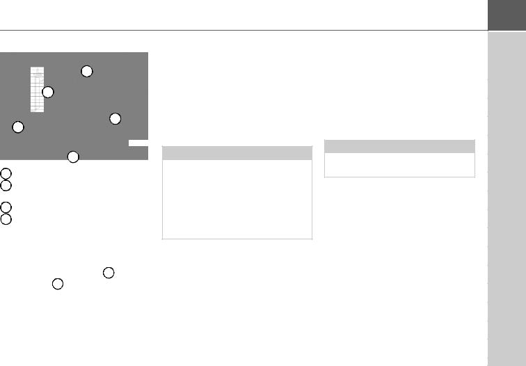
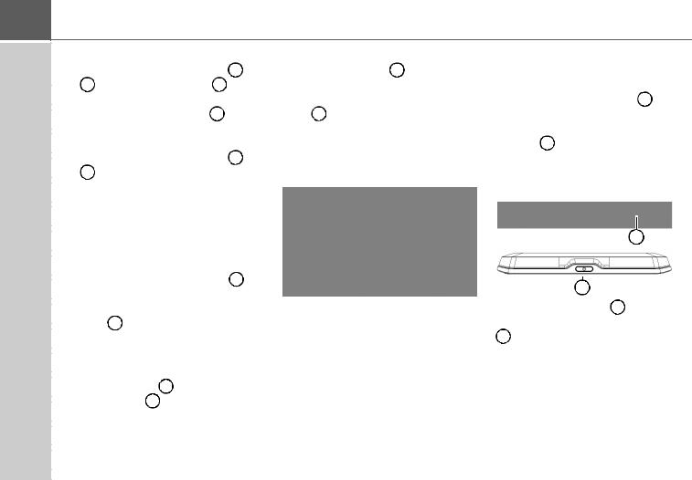
Front of unit with controls and displays
1 Back button 
Model dependent: either on the left bottom side of the screen or in the left top corner of the housing.
Press = Back function in most applications Press and hold = Open the main menu
2 Touch screen showing the main menu selected
3Touch screen key
Press = activates the corresponding key command
4Microphone (depending on the model, sometimes in the right top corner, too))
17

>>> OVERVIEW OF THE NAVIGATION DEVICE(model dependent)
Model dependent, the arrangement of the connections can differ on the bottom side of the device.
|
|
|
|
|
|
|
|
|
|
|
|
|
|
|
|
|
|
|
|
|
|
|
|
|
|
|
|
|
|
|
|
|
|
|
|
|
|
|
|
|
|
|
|
|
|
|
|
|
|
|
|
|
|
|
|
1 |
5 |
4 |
2 |
3 |
|||||
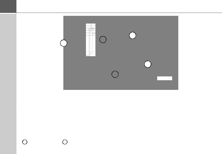
Top of the unit |
Underside of the unit |
||
1 |
ON/OFF switch |
2 |
Slot for Micro SD card |
|
|
3 |
Mini USB connection / connection for power supply |
|
|
4 |
Connection for reversing camera |
|
|
5 |
Connection for vehicle integration |
|
|
|
|
|
|
|
|
|
|
|
|
|
|
|
|
|
|
|
|
|
|
|
|
|
|
|
|
|
|
|
|
|
|
|
|
|
|
|
|
|
|
|
|
|
|
|
|
|
|
|
|
|
|
|
|
|
|
|
|
|
|
|
|
|
|
|
|
|
|
|
|
|
|
|
|
|
|
|
|
|
|
|
|
|
|
|
|
|
|
|
|
|
|
|
|
|
|
|
|
|
1 |
|
2 |
3 |
4 |
||||
|
|
||||||||
|
|
|
Underside of the unit |
|
|
||||
|
|
|
|
|
|||||
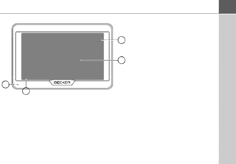
Top of the unit |
|
|
|||||||
|
|
|
2 |
Slot for Micro SD card |
|
|
|||
1 |
Standby switch (sleep mode) |
|
|
||||||
|
|
|
3 |
Mini USB connection / connection for power supply |
|||||
|
|
|
|||||||
|
|
|
4 |
On/Off switch (I/O) |
|
|
|||
|
|
|
|
|
|
|
|
|
|
|
|
|
|
|
|
|
|
|
|
|
|
|
|
|
|
|
|
|
|
|
|
|
|
|
|
|
|
|
|
18

|
|
|
|
|
|
|
|
|
|
|
GENERAL OPERATION |
Maintenance and care |
|
|
|
Your mobile navigation system was |
• Do not store your mobile navigation |
||||||
The unit is maintenance-free. |
|
|
|
designed and manufactured with great |
|
system in cold environments. During |
|||||
|
|
|
care and should be treated with equal |
|
operation, when the unit warms up to |
||||||
For proper |
care, |
a |
commercially |
|
|
||||||
|
care. You will enjoy your mobile naviga- |
|
operating temperature, moisture may |
||||||||
available |
cleansing fluid |
for |
electrical |
|
|
||||||
|
tion system for a long time to come if you |
|
form internally, causing damage to |
||||||||
devices |
may |
be |
applied |
using a |
soft |
|
|
||||
|
observe the recommendations listed in |
|
electronic components. |
||||||||
damp cloth. |
|
|
|
|
|
|
|
|
|||
|
|
|
|
|
|
|
the following: |
• |
Do not drop your mobile navigation |
||
|
|
|
|
|
|
|
|
|
|||
|
|
|
|
|
|
|
|
• Protect your mobile navigation unit |
|
system unit, protect it from shocks and |
|
¤ Danger! |
|
|
|
|
|
|
|
||||
Danger to life by electrocution. |
|
|
and the accessories from water and |
|
do not shake it. Improper handling can |
||||||
|
|
moisture. If your unit has been |
|
damage components within the unit. |
|||||||
Always |
switch |
off |
the |
unit |
and |
|
|
||||
|
exposed to moisture, switch it off |
• |
Never use corrosive or aggressive |
||||||||
disconnect the mains power supply |
|
||||||||||
|
immediately and disconnect the power |
|
chemicals, cleaning solutions or |
||||||||
unit before cleaning the unit, supplied |
|
|
|||||||||
|
supply. Allow to dry at room |
|
aggressive detergents for cleaning. |
||||||||
components, or accessories. |
|
|
|
||||||||
|
|
temperature. |
All the above information applies equally |
||||||||
|
|
|
|
|
|
|
|
|
|||
|
|
|
|
|
|
|
|
|
• Do not operate your mobile navigation |
to |
the mobile navigation system, the |
Note: |
|
|
|
|
|
|
|
|
|||
|
|
|
|
|
|
|
|
system in a dusty or dirty environment |
rechargeable battery, the mains charg- |
||
Do not use any aggressive or abrasive |
|
||||||||||
|
and do not store it in such an |
ing and car power adapters as well as all |
|||||||||
substances |
or |
cloths |
which |
may |
|
||||||
|
environment. |
accessories. Should one of these parts |
|||||||||
damage the surface. |
|
|
|
|
|
||||||
|
|
|
|
|
• Do not store your mobile navigation |
not work properly, please contact your |
|||||
A micro-fibre |
cloth |
is |
particularly |
|
|||||||
|
system in hot environments. High |
authorised dealer. |
|||||||||
suitable for the display. |
|
|
|
|
|||||||
|
|
|
|
temperatures can shorten the service |
|
|
|||||
The unit must not be exposed to water. |
|
|
|
||||||||
|
life of electronic components in your |
|
|
||||||||
|
|
|
|
|
|
|
|
|
|
|
|
|
|
|
|
|
|
|
|
|
|
|
|
|
|
|
|
|
|
|
|
|
unit, damage the rechargeable |
|
|
|
|
|
|
|
|
|
|
|
batteries and cause certain plastics to |
|
|
|
|
|
|
|
|
|
|
|
warp or melt. |
|
|
>>> |
19

>>> |
20
GENERAL OPERATION
Battery quality declaration
The capacity of the rechargeable battery in your mobile navigation system decreases with every charging/ discharging cycle. Improper storage at excessively high or low temperatures may also cause a gradual deterioration of capacity. Consequently, the operating time may be substantially reduced even in the case of a fully charged battery.
Display quality declaration
In some cases, for technical reasons, a few discoloured dots (pixels) may be visible on the display. Some pixels may also appear brighter or darker. However, such instances do not represent a product flaw.
Start-up
Once the Navigation device has been unpacked and checked for damage, the unit can be started up. The individual start-up steps are:
•connect to power supply.
•switching on the unit.
•ensuring antenna reception (if navigation is desired)
Power supply
Note:
You can charge the Navigation device via the car charger cable included in the scope of delivery or via the optionally available mains power supply unit.
When the Navigation device is connected to a PC, it is supplied with power via the PC and does not consume battery power.
GENERAL OPERATION
Using the battery
The internal power supply is via the integrated rechargeable battery. The rechargeable battery is maintenancefree and does not require any particular care.
You are alerted by a warning message when the battery should be recharged. After the alert, the device can still be used for approximately 10 minutes before switching off automatically.
Note:
Note that if the battery is completely discharged, it may take up to a minute before the device can be switched on again.
Note:
In the event of a defective battery, please contact your authorised dealer. Please do not attempt to remove the battery yourself.
Connection for the cigarette lighter
Note:
If the cigarette lighter has recently been used and is still hot, wait until the lighter socket has cooled down.
Connect the power supply via the vehicle battery and the cable provided for the cigarette lighter as follows:
>Grasp the connector of the connection cable and insert it gently without force into the connector socket of the navigation device up to the stop, or in the case of a device with an active cradle, on the underside of the supporting plate. (Model dependent, this step is not required on navigation devices with magnetic holders)
>Insert the adapter into the cigarette lighter.
Note:
When the engine is switched off, the power supply slowly discharges the vehicle battery via the cigarette lighter! Do not therefore operate the Navigation device for long periods with the engine switched off.
To receive TMC messages (depending on the model), the power supply must be connected to the supporting plate in the case of a device with an active cradle.
>>> |
21

>>> |
22
GENERAL OPERATION
Connection to the mains outlet
¤ Danger!
Make sure that your hands are not wet and that the power supply unit is dry. Only connect the power supply unit to a permissible mains power supply.
Connecting to power supply
Connection to the public mains grid is achieved using the optionally available mains power supply unit. Please proceed as follows to connect to the mains:
>Hold the connector and push it all the way into the connecting socket in the Navigation device without using excessive force.
>Insert the plug of the power supply unit into the socket.
Note:
Remove the power supply unit when not using the Navigation device for longer periods of time.
TMC antenna (depending on the model)
The supplied TMC antenna is integrated into the cable for power supply.
The TMC antenna runs in parallel with the the cigarette lighter cable in the delivered condition.
If the TMC reception is poor, you must remove the cable of the TMC antenna from the cable for the cigarette lighter.
(Model dependent, the cable cannot be disconnected on navigation devices with magnetic holders)
Note:
The TMC antenna must be installed in such a way that it does not distract you while driving.
GPS antenna
Unit antenna
The GPS antenna is integrated into the housing.
Note:
The integrated GPS antenna is not suitable for use in vehicles with antiglare windows (metalised thermoglass or metal foil, indicated by the window label - SIGLA SOL, SIGLA CHROM, SIGLA, KOOL-OF, SUNGATE, etc.) and vehicles with fine-meshed heating wires in the windows.
|
|
|
|
GENERAL OPERATION |
||||
Cable for vehicle integration |
|
Memory card |
||||||
Note: |
||||||||
(depending on model, optional) |
|
|
|
|
|
|
|
|
Once the cable is connected, the |
Your Navigation device has a slot for a |
|||||||
With a 4-pin 3.5mm jack cable you can |
loudspeaker of the basic device is |
micro SD memory card. |
||||||
switched off. |
As the map data is stored in an internal |
|||||||
integrate your Navigation device |
||||||||
|
memory on the Navigation device, the |
|||||||
|
||||||||
seamlessly into your vehicle. |
|
|||||||
|
slot for a micro SD memory card is used |
|||||||
• connect your Navigation device to the |
|
|||||||
Cable for rear view camera |
for updates and for viewing images. |
|||||||
phone mute function of your audio |
||||||||
The memory card can also be used for |
||||||||
system. If the cable is connected |
(depending on the model, |
|||||||
supplementing the map data. |
||||||||
correctly, your audio system will mute |
optional) |
|
|
|
|
|
|
|
the car radio during navigation |
|
|
|
|
|
|
||
announcements. |
You can connect your rear view camera |
|
|
|
|
|
|
|
• connect your Navigation device to your |
|
|
|
|
|
|
||
to your navigation device using a 4-pin |
|
|
|
|
|
|
||
audio system for output of the audio |
2.5mm AV cable. Insert the cable into the |
|
|
|
|
|
|
|
signal. |
socket provided on the back of the basic |
|
|
|
|
|
|
|
|
unit, also see page 18. |
|
|
|
|
|
|
|
|
|
|
|
|
|
|
|
|
GND |
|
Telephone Mute: |
|
Audio-R |
GND |
Audio-L |
Video |
|
Audio-R |
|
Audio-L |
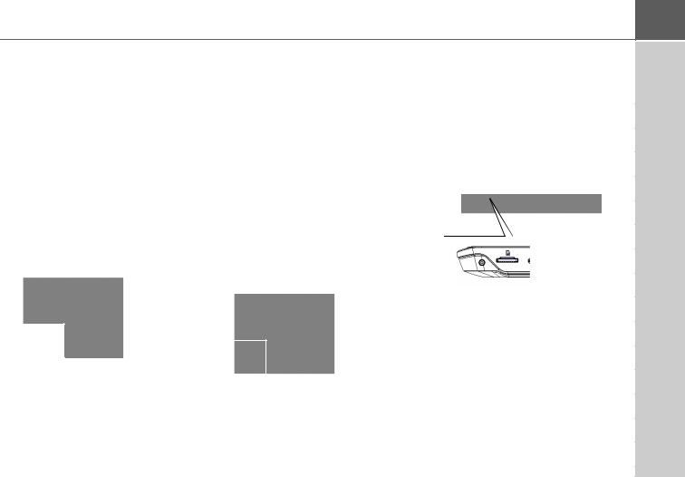
The card slot is located on the bottom side of the device. The card slot is equipped with a spring-actuated locking and ejector mechanism.
> Plug the cable into the designated 3.5 |
You can make the necessary settings in |
|
the chapter “Rear View camera” on |
||
socket on the underside of the device. |
||
page 121. |
||
|
>>> |
23

>>>GENERAL OPERATION
Inserting the memory card
>Remove the memory card from its packaging without touching or soiling the contact bar.
>Hold the memory card so that the contact strip is facing towards the rear of the unit.
>Guide the memory card into the card slot.
>Exert a little pressure and slide the memory card into the card slot until it snaps in.
Unit bracket
The Navigation device can be attached directly to the windscreen with the unit holder.
Note:
The Navigation device and unit bracket must not be exposed to long periods of direct sunlight. Temperatures inside the vehicle of +70 °C and higher may damage parts of the bracket.
Ejecting the memory card
The card slot ejects the card so that you can pull it out with two fingers.
>Use your finger to gently press the memory card against the spring force into the card slot and then release it.
The card is ejected.
>Remove the memory card and place it in the packaging while ensuring not to touch contact bar.
Fitting the unit bracket
Note:
Fasten the unit holder such that your field of vision is not impaired when the Navigation device is installed and ensure that the unit is outside the deployment area of the airbag.
Ensure that the electrical connection cable does not hamper you from accessing the vehicle's controls.
Clean the attachment surface on the windscreen to ensure that it is clean and free of grease. Do not use greasy or soapy cleaning agents.
24

GENERAL OPERATION
7 |
2 |
1 |
7 |
2 |
1 |
|||||
|
|
|
|
|
|
|
|
|
||
|
|
|
|
|
|
|
|
|
|
|
|
|
|
|
|
|
|
|
|
|
|
|
|
|
|
|
|
|
|
|
|
|
|
|
|
|
|
|
|
|
|
|
|
|
|
|
|
|
|
|
|
|
|
|
|
|
|
|
|
|
|
|
|
|
|
3 |
6 |
|
3 |
|
|
|
|
|
|
|
|
|
|
|
|
|
|
|
|
4
64
1 Suction surface
2 Base
3 Lever
4 Fastening screw
6 Carrier plate
7 Release button
Similar to figure, on devices with magnetic holders no unlocking button is present 7 .
On the windscreen
The unit holder can be attached directly to the windscreen using the suction mechanism.
>Press the carrier plate onto the four retaining lugs of the unit holder.
>Select a suitable spot to attach.
> Loosen the fastening screw 4 slightly.
>Press the base 2 with its suction surface 1 against the windscreen. Turn the unit holder such that the carrier plate is positioned roughly in the desired viewing direction.
>Press the lever 3 down.
The holder has attached itself firmly to the windscreen. It can now be adjusted with precision. In order to remove it, operate the 3 lever again.
>>> |
25
>>> |
26
GENERAL OPERATION
Adjusting the unit holder’s position
> Loosen the fastening screws |
4 and |
5 until the carrier plate 6 |
can be |
moved without using excessive force.
>Move the carrier plate 6 to the required position and hold it in this position.
> Tighten the fastening screws 4 and 5 sufficiently so that the Navigation device is held securely in place when the vehicle is in motion.
Attaching the Navigation device
>Position the Navigation device with the attachment point on the bottom of the housing, onto the carrier plate 6 .
>Without using excessive force, press the Navigation device onto the carrier plate 6 . The Navigation device locks into place.
Devices with magnetic holders
The unlocking button 7 is not present. First place the navigation device with the upper mounting point onto the carrier plate 6 and fold down the navigation device. The magnet holds the navigation device securely on the carrier plate. To remove the navigation device, first take it off from the carrier plate at the bottom.
Switching the Navigation device on/off (model dependent)
With the ON/OFF switch (I/O) 1 you can switch the Navigation device on or off completely.
With the 2 button on the upper side of the Navigation device you can switch the device to sleep mode or switch it from sleep mode again.
1
2
For devices without the 1 button on the underside (model dependent): With the 2 button you can switch the device off, on or to the sleep mode.
Removing the Navigation device
Press the button 7 on the top of the carrier plate 6 . This unlocks the Navigation device which can be removed from the carrier plate.

GENERAL OPERATION
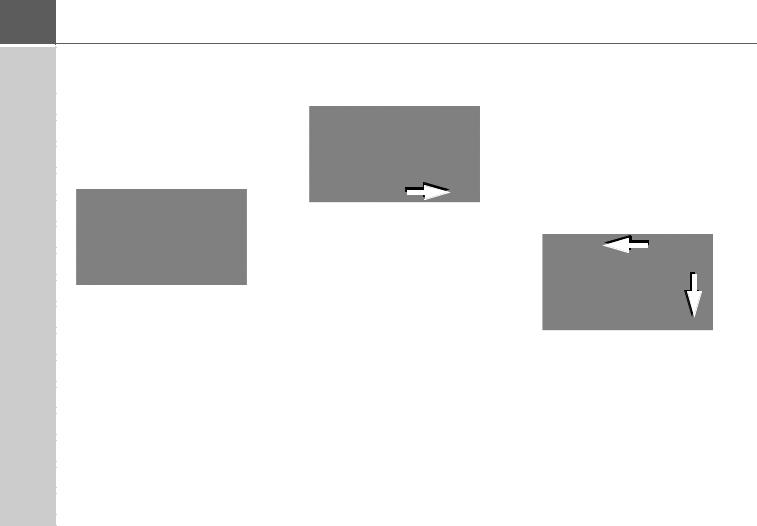
Switching on
>Press the button on the top of the Navigation device.
The unit is switched on. The manufacturer's logo appears on the touchscreen.
When the Navigation device is started for the first time, the language selection is displayed automatically.
Using the  buttons or the scroll wheel, it is possible to scroll through the list in the direction of the relevant arrow.
>Press the button for the required language.
>The selection is confirmed by pressing
OK.
> Then select the desired voice.
Note: for models with TTS
Voices with a (TTS) tag support the text- to-speech function (e.g. announcing roads and reading out text messages).
A short example announcement is given.
>Confirm your selection by pressing the OK button.
The following prompt appears shortly afterwards:
>If you agree to the request contained in this prompt, press the OK button.
Note:
Use of the Navigation device is only permitted in accordance with the national road traffic regulations applicable at the time.
Switching off (depending on model)
You can switch the unit off at any time.
>Press the button on the top of the Navigation device.
The Navigation device switches to sleep mode.
>Before finally switching off the navigation device, press the I/O switch on the underside of the device to 0.
>>> |
27

>>> |
GENERAL OPERATION
For devices without the I/O switch on the |
|
Basic information about the |
Operation |
|
|
|||||
underside: |
|
|
|
|
|
touch screen |
When you touch a button on the touch |
|||
> Press the switch on the top of the |
|
screen, the button in question is briefly |
||||||||
|
|
|||||||||
navigation |
device |
for |
longer |
than |
|
The Navigation device is fitted with a |
shown outlined in red to confirm the |
|||
3 seconds to finally switch it off. |
|
|
touch screen. |
selection. |
|
|
||||
|
|
|
|
|
|
|
If you touch a button that is not active at |
|||
Note: |
|
|
|
|
|
|
||||
|
|
|
|
|
Note: |
the moment, a short signal tone sounds. |
||||
We recommend that you place |
the |
|
||||||||
|
To ensure that the display's surface is |
|
|
|
|
|||||
Navigation device in sleep mode in the |
|
|
|
|
|
|||||
|
not damaged, you may only touch it with |
Calibration |
|
|
||||||
event of short interruptions to operation |
|
|
|
|||||||
(of up to a week). |
|
|
|
|
your fingers or a blunt, non-smearing |
If the |
touch |
screen starts |
responding |
|
|
|
|
|
object. |
||||||
This significantly reduces the switch-on |
|
imprecisely, |
calibration |
should be |
||||||
|
|
|||||||||
time and the Navigation device finds the |
|
|
undertaken. |
|
|
|||||
satellites required for navigation much |
|
|
The calibration function is started from |
|||||||
faster. |
|
|
|
|
|
|
the |
menu (see also page 137). |
||
If route guidance was active when sleep |
|
|
|
|
|
|
||||
mode is activated, it is automatically |
|
|
|
|
|
|
||||
resumed if the Navigation device is |
|
|
|
|
|
|
||||
switched back on again within approx. |
|
|
|
|
|
|
||||
4 hours. |
|
|
|
|
|
|
|
|
|
|
If the device cannot be switched off |
|
|
|
|
|
|
||||
anymore or no longer works reliably, it |
|
|
|
|
|
|
||||
is possible to switch off devices without |
|
|
|
|
|
|
||||
I/O switches completely by pressing the |
|
|
|
|
|
|
||||
button on |
the top |
for |
longer |
than |
|
|
|
|
|
|
7 seconds. |
|
|
|
|
|
|
|
|
|
|
|
|
|
|
|
|
|
|
|
|
|
28
|
|
|
|
GENERAL OPERATION |
|
Basic information about the |
You |
can tell whether a telephone is |
If route guidance is already active, the |
||
menus |
already connected by the symbol on the |
current destination address and a button |
|||
Phone button. |
|
for cancelling route guidance will be |
|||
|
|
||||
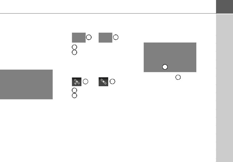
During operations, you are assisted by |
|
1 |
2 |
displayed between the two rows of |
|
various menus and entry windows. |
|
buttons. |
|||
The main menu |
1 |
Telephone connected |
|
||
2 |
Telephone not connected |
|
|||
The top menu level is the main menu. |
|
||||
|
|
|
|
||
The individual applications are started |
A satellite symbol at the right of the |
|
|||
from the main menu. |
1 |
||||
status line shows you whether there is |
|||||
|
|||||
|
currently GPS reception or not. |
|
|||
|
|
1 |
2 |
Press the button 1 to cancel route |
|
|
|
guidance to the displayed destination |
|||
|
1 |
GPS reception |
|
directly in the main menu. |
|
|
|
|
|||
|
2 |
No GPS reception |
|
|
|
You will find information about the individual applications in the corresponding main chapters.
In addition to the individual applications, the main menu also contains further information and operating options.
>>> |
29
>>> |
30
GENERAL OPERATION
Entries made with the entry menu
Some applications require entries to be made via the entry menu. The entry menu is operated in a similar way to a keypad.
The keyboard layout can be switched between ABC and QWERTZ, see page “Keyboard layout” on page 134
The character entered on the keypad is displayed in the top line of the entry menu. The central area is used to enter characters. Help functions are provided in the right line. Descriptions of how to operate the menu are provided below.
Entering characters
Characters are entered by pressing the keys in the central area.
Once the entry is complete, the process is concluded by pressing the  key and the entry passed on to the Navigation device for processing.
When a navigation destination is entered, the Navigation device compares the data with the stored data.
Only those letters that are still possible area vailable for selection.
Characters that cannot be selected are displayed greyed out.
Accepting proposals
During entry, the Navigation device makes proposals in the uppermost line. The proposals take into account your usage habits. For example, if you enter the city of Hamburg often, then after you enter the letter "H" the proposal "Hamburg" is automatically displayed.
If no preferences are known for the letter entered, then cities/locations suitable for the entry are displayed as proposals.
>To accept the proposal, you may press
either the input field or the  button.
 Loading...