

Bang & Olufsen BeoVision Avant 32 DVD MKIII Repair Manual
BeoVision Avant 32 DVD MKIII
Type 846x
Service Center repair guide
English, German, French, Italian, Spanish
ABO-CENTER v/HENRIKSENS ELEKTRONIK

CONTENTS
Survey of modules .............................................................................. 1.1
How to service .................................................................................... 1.2
Specication guidelines for service use ................................................. 1.4
Type survey and cautions ..................................................................... 2.1
Wiring diagram ............................................................................................. 3
Available parts ............................................................................................... 4
Adjustments etc. ............................................................................................ 5
Illustrations ......................................................................... 5.121 - 5.123
English German French Italian Spanish
Adjustments 5.1 5.25 5.59 5.73 5.97
Service mode 5.12 5.36 5.60 5.84 5.108
ServiceTool 5.22 5.46 5.70 5.94 5.118
PIN-code 5.23 5.47 5.71 5.95 5.119
Dismantling ................................................................................................... 6
Illustrations ............................................................................. 6.37 - 6.40
English German French Italian Spanish
Dismantling 6.1 6.8 6.15 6.22 6.29
Insulation test ................................................................................................ 7
There is no Brief operation guide in this Service Center repair guide.
Instead an english version of the user guide is enclosed the back-up suitcase.
ABO-CENTER v/HENRIKSENS ELEKTRONIK
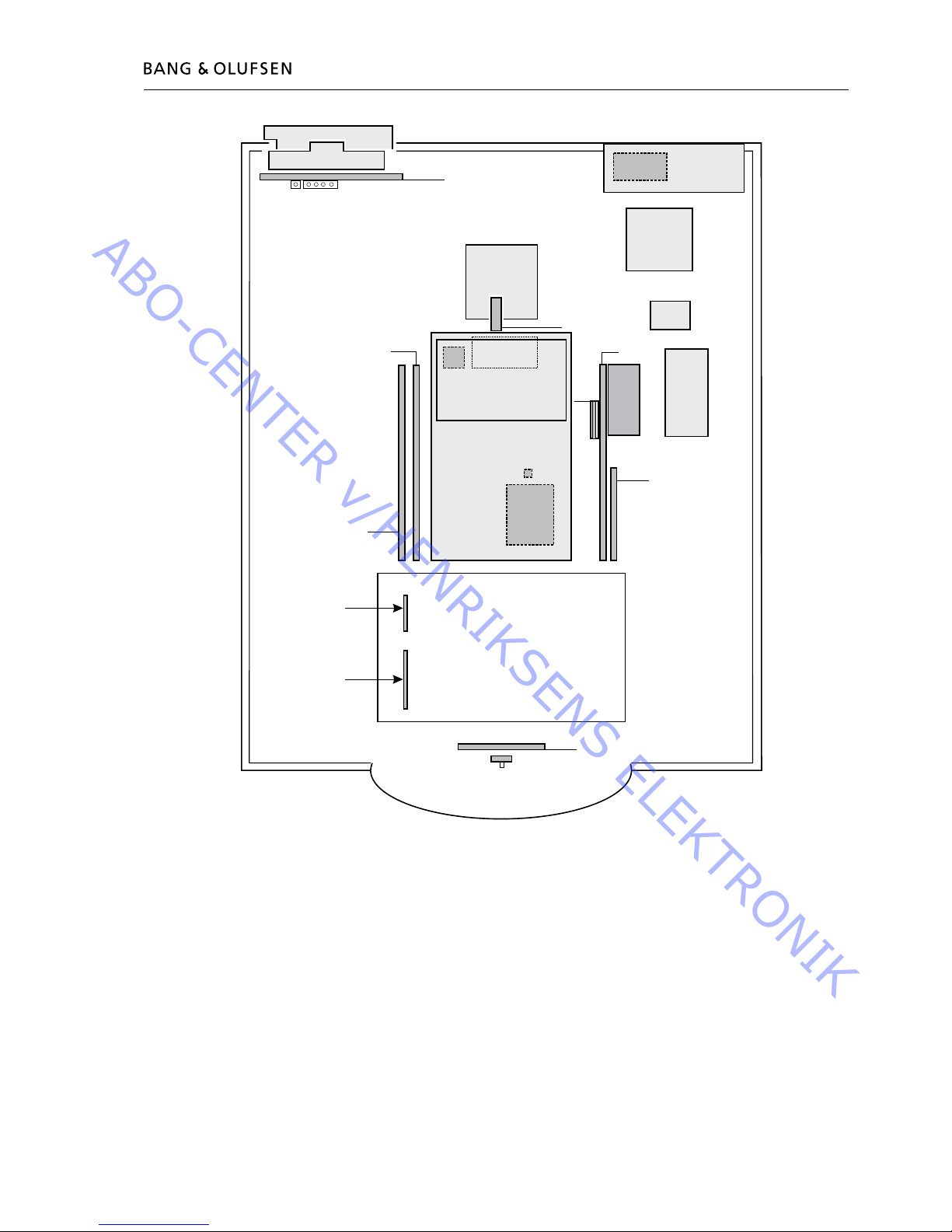
Survey of modules 1.1
996
997
9
63
58
57
59
3
74
10
2
7
1
6
6
1
32
14
85
4
8
0
81
75
60
5
995
*21
*22
PCB1, 2, 3, 4, 5, 6, 7, 14, 32, 61, 63, 85 Main chassis, 999Module
PCB9 EFC
PCB10 Sound output
PCB32 AC3 with DTS
PCB57, PCB58, PCB59 Display panel
PCB60 Mains distribution
PCB61, PCB85 STB Controller
PCB74 DVD Power Supply
PCB75 DVD SMPS
PCB80, PCB81 Motor stand
PCB996 DVD mechanism incl. PCB995
PCB997 DVD Main chassis
*PCB21, PCB22 DVB-S
* = Optional
ABO-CENTER v/HENRIKSENS ELEKTRONIK
1.2 How to service, English-German-French
How to service
BeoVision Avant 32 DVD is supposed to be serviced in the customers home!
In order to support the general service strategy, a Back-up suitcase is available which
contains the TV chassis and additional modules.
With this it is possible to easily carry out service in the customers home. Feature
modules are included.
If the TV chassis is replaced, leave the EEPROM in the set. The chip is located on a
separate very small module.
By doing so, the entire identity of the set is maintained.
After having replaced the faulty chassis, please read out error codes, write them
down and let them follow the chassis going for repair.
After that clear error codes.
The ServiceTool is used to change the Region setup.
Serviceanleitung
Das BeoVision Avant 32 DVD ist für den Service beim Kunden konzipiert!
Zur Unterstützung der allgemeinen Servicestrategie steht ein Servicekoffer zur
Verfügung, der das TV-Chassis und weitere Module enthält.
Hiermit kann der Service beim Kunden einfach durchgeführt werden. Module für
Spezialfunktionen sind im Koffer enthalten.
Bei Austausch des TV-Chassis muss das EEPROM im Gerät bleiben. Der Chip bendet
sich auf einem sehr kleinen separaten Modul.
Durch Beibehalten des EEPROM bleiben alle gespeicherten Gerätedaten erhalten.
Nach dem Austausch des defekten Chassis bitte die Fehlercodes auslesen, notieren
und dem zur Reparatur eingeschickten Chassis beilegen.
Anschließend die Fehlercodes löschen.
Das ServiceTool wird zur Änderung der Regionseinstellung benutzt.
Comment effectuer la maintenance
La maintenance du BeoVision Avant 32 DVD est supposée être effectuée chez le
client !
An d’assurer la stratégie de service général, une valise de sauvegarde contenant
le châssis du téléviseur et des modules supplémentaires est disponible.
Ce matériel permet d’effectuer facilement l’intervention sur site chez le client. Des
modules de fonction sont inclus.
En cas de remplacement du châssis du téléviseur, laisser l’EEPROM dans le téléviseur.
La puce se situe sur un tout petit module séparé.
Procéder ainsi permet de maintenir l’identité intégrale du téléviseur.
Après avoir remplacé le châssis défectueux, veuillez faire une lecture des codes
d’erreur, les noter et les transmettre avec le châssis envoyé pour réparation.
Ensuite, effacez les codes d’erreur.
Cette opération se fait à l’aide de l’outil de maintenance.
ABO-CENTER v/HENRIKSENS ELEKTRONIK

How to service, Italian-Spanish 1.3
Cómo realizar el servicio
El servicio del BeoVision Avant 32 DVD se debe realizar en el domicilio del cliente.
En apoyo de la estrategia general de servicio, hay una maleta auxiliar que contiene
el chasis del televisor y módulos adicionales.
De este modo, se puede realizar fácilmente el servicio en el domicilio del cliente.
Se incluyen módulos de funciones.
Si sustituye el chasis del televisor, deje la EEPROM en el aparato. El chip está ubicado
en un módulo separado muy pequeño.
Haciendo esto, se mantiene la identidad total del aparato.
Después de haber sustituido el chasis defectuoso, lea los códigos de error, anótelos
y adjúntelos con el chasis para su reparación.
A continuación, borre los códigos de error.
ServiceTool se utiliza para cambiar la conguración de la región.
Modalità dell’assistenza
BeoVision Avant 32 DVD è stato concepito per poter essere riparato presso il
domicilio del cliente!
A sostegno della strategia generale sulla quale si basa il servizio di assistenza, viene
messa a disposizione una valigetta di back-up, contenente lo chassis TV, nonché
moduli supplementari.
Questa strumentazione consente di effettuare agevolmente le riparazioni,
direttamente a casa del cliente. Sono compresi anche moduli per le funzioni speciali.
Qualora venga sostituito lo chassis TV, occorrerà lasciare la EEPROM nel set. Il chip
si trova su di un modulo molto piccolo, a parte.
Attenendosi a queste istruzioni, verrà preservata l’identità del set nel suo complesso.
Dopo aver sostituito lo chassis difettoso, leggere i codici di errore, annotarli ed
allegarli allo chassis inviato in riparazione.
Cancellare quindi i codici di errore.
Lo strumento ServiceTool viene utilizzato per modicare l’impostazione della regione.
ABO-CENTER v/HENRIKSENS ELEKTRONIK
1.4 Specication guidelines for service use
SPECIFICATION GUIDELINES FOR SERVICE USE BeoVision Avant 32 DVD MKIII
CTV
CTV system See type survey
Video Technology 100Hz with motion compensation
Dimensions W x H x D 84 x 109 x 61cm
Weight 86 kg
Cabinet nish Black, Silver, Light blue, Dark grey
Power consumption Typical 134 watt/stand-by < 2 watt
Terminal included Beo4
Stand turning function +/- 35 degrees, remote operated, two memory positions
Picture tube/Visual picture 16:9, 81 cm - 32”/76 cm - 30” (16:9)
Wide-Screen, Real Flat
Curtain Electronic
Contrast screen Anti-reex coating
VisionClear Auto picture adjustment
Auto cut-off
Digital CTI
Adaptive Luminance Peaking
Scan Velocity Modulatioin
Improved letterbox
Motion Clear
Teletext Teletext level 2, 1780 pages
Wide Screen Signalling (WSS)
Fastext (FLOF), 4 memory pages per program
17 teletext languages in 7 groups
Group 0 English, German, Swedish, Italian, French, Spanish/Portuguese,
Czech/Slovak
Group 1 Polish, German, Swedish, Italian, French, Serbocroat, Czech/Slovak,
Romanian
Group 2 English, German, Swedish, Italian, French, Spanish/Portuguese, Turkish
(Russian) Group 3 English, Russian, Estonian, Czech/Slovak, German, Lithuanian/Lettish,
Ukrainian
(Greece) Group 4 English, German, Swedish, Italian, French, Spanish/Portuguese,
Turkish, Greek
(Arabic) Group 5 English, Arabic, French
(Hebrew) Group 6 English, Hebrew, Arabic
Tuning Autotune, program move and automatic naming
Tuner range 45 - 860 MHz, VHF, S, Hyper, UHF
TV programmes 99
Picture in Picture (Dual Screen) Built in.
Stereo decoders A2 + Nicam
PIN-code protection With pin-code or Disabled
Set Top Box Controller (STB-C) Built in
Controlling boxes with Beo4 Supported boxes : Se list at Bang & Olufsen Retail System (via internet)
Controlling one or two boxes (2 x STB) 1 box controlled by use of the IR-blaster included.
2 boxes controlled by use of the IR-blaster included and IR Y-adaptor
(6174171) and one more IR-blaster (8330352).
DVD
Disc sizes 12 cm - 5”
Frequency range 20Hz - 20KHz
Playback the following: DVD-Video, Video CD, CD-DA, CD-R, CD-RW, CD-MP3
Multistandard PAL/NTSC
Signal-to-noise-ratio Typical 100 dB, A weighted, in Audio mode
DVD Region According to type
ABO-CENTER v/HENRIKSENS ELEKTRONIK
Specication guidelines for service use 1.5
Loudspeakers
Power amplier modules 4 units
Long term max. output power per module 39 watts
Frequency range 50 - 20,000 Hz
Max. sound pressure level 96 dB
Cabinet principle/ net volume Bass Reex / 3.5 litres
Woofer 115 mm - 4”
Tweeter 18 mm - 3/4”
Bass equalizer Adaptive
Magnetic shielded Yes
Dolby® Digital Decoder
Decoding capabilities Dolby® Digital 5.1 channel decoding
Dolby® Pro-Logic decoding of two channel Dolby® Digital
Dolby® Pro-Logic decoding of two channel PCM
Dolby® Pro-Logic decoding of two analogue channels (Lt/Rt)
Automatic format detection(Dolby® Digital, PCM)
Calibration 3 channel tone control & loudness (L/C/R)
Bass management, Delay management
Sound modes (Speaker 1 - 5) Speaker 1 : Stereo internal speakers (subwoofer muted)
Speaker 2 2.0/2.1 : Stereo external speakers / Stereo external
speakers + subwoofer
Speaker 3 3.0/3.1 : Dolby®-3 stereo / Dolby®-3 stereo + subwoofer
Speaker 4 4.0/4.1 : Stereo-4 / Stereo-4 + subwoofer
Speaker 5 5.0/5.1 : Dolby® Digital or Dolby® Pro-Logic Surround /
Dolby® Digital + subwoofer
Connections
Digital audio input 2 x Coax phono, Input-1 for AV-scart, Input-2 for DECODER-scart
External BeoLab loudspeakers 5 x Power Link (left, right, rear left, rear right, subwoofer. - internal
center)
Loudspeakers recommended, Front/Rear BeoLab 5, BeoLab 1, BeoLab 8000, BeoLab 6000, BeoLab 4000,
BeoLab 4500
Loudspeaker recommended, subwoofer BeoLab 2
System modulator Splitter/system modulator output to link room
(BeoLink Video Distribution)
Frequency range 479 - 831 MHz (in 1 MHz step), Dual side band
Audio Mono
According to type :
FM sound system G : 5.5MHz, FM sound system I : 6MHz
Connection 1 x 75 ohms aerial male
Satellite modul (DVB-S) : (optional)
Tuner range 950 - 2150 Mhz
Programmes 9999 TV/Radio
Down conv. supply 14/18 Volts control, Tone control (22 Khz) and DiSEqC 1.0
Conditional Access Common Interface - 2 slots PCMCIA
Middleware MHP (Multimedia Home Platform)
Input 1 x F-connectors (sat dish)
Subject to change without notice
ABO-CENTER v/HENRIKSENS ELEKTRONIK
1.6 Specication guidelines for service use
Connections
TV Input 1 x 75 ohms aerial female
System modulator 1 x 75 ohms aerial male (splitter/system modulator output).
According to type : System G or I RF output
V.TAPE - AV - Decoder 3 x 21-pin sockets
V.TAPE : CVBS in/out, RGB in (automatic 16:9 sense(pin-8), B&O AVL)
AV : CVBS in/out, RGB in, S-VHS in/out (automatic 16:9 sense
(pin-8), automatic S-VHS conguration, B&O AVL)
DECODER : CVBS in/out (automatic 16:9 sense (pin-8))
BeoLink 1 x Master Link
Dolby® Digital
- External BeoLab speakers 5 x Power Link (2 x front, 2 x rear, 1 x subwoofer)
- Digital audio input 2 x Coax phono, Input-1 for AV-scart, Input-2 for DECODER-scart
Camcorder / Auxiliary 3 x Phono sockets (video in/audio L-R in) *)
S-Video (S-VHS) 1 x Y/C playback 4-pin socket
Headphone socket 1 x Mini jack
V.TAPE DECODER 1 x 21-pin for V.TAPE decoder (video, L, R in/out)
Satellite modul (optional) 1 x F-connector input (1 x 75 ohms)
STB-Controller output 1 x Mini jack (stereo for 2 x IR-blaster with IR-Y-adaptor)
*) Possible to congure Set Top Box (STB) at Camcorder input and control via STB-Controller
Link compatibility
Master Link
Optional features / modules
Digital satellite module (DVB-S) 4032 (will be launched later)
ABO-CENTER v/HENRIKSENS ELEKTRONIK
Specication guidelines for service use 1.7
3
2
1
4
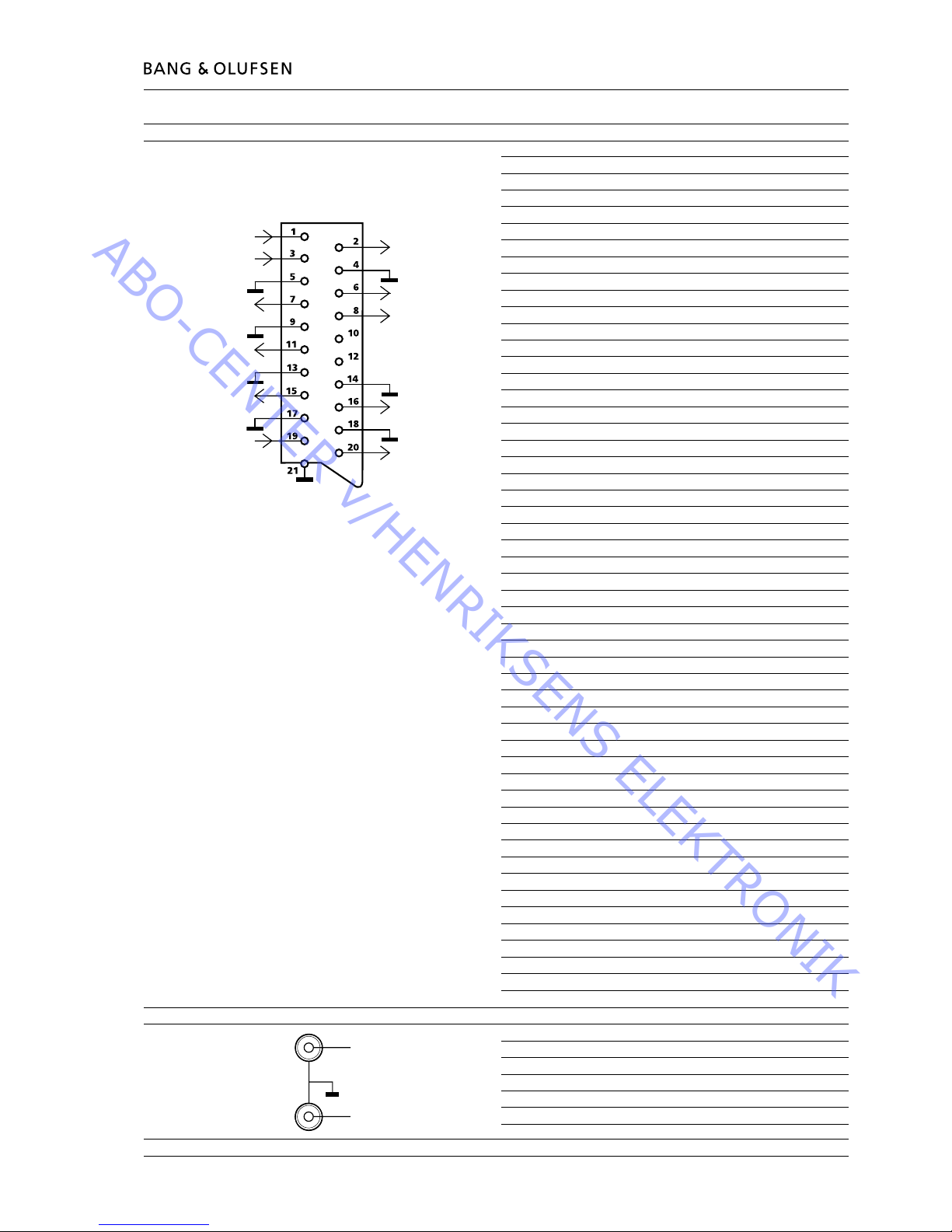
V.TAPE (AV1), AV (AV2) & DECODER (AV3) Pin 1 Audio R out 1V RMS 820 ohms
Pin 2 Audio R in 1V RMS 47 kohms
Pin 3 Audio L out 1V RMS 820 ohms
Pin 4 Audio GND
Pin 5 Blue GND
Pin 6 Audio L in 1V RMS 47 kohms
Pin 7* Blue in 0.7 Vpp 75 ohms (note 1)
Pin 8 Play voltage: Logic 0 = 0V to 2V
Logic 1 = 9.5V to 12V (4:3 info)
5V = 16:9 info
Data out (AV2 only)
Pin 9 Green GND
Pin 10 Not used
Pin 11* Green in 0.7 Vpp 75 ohms
Pin 12 Not used
Pin 13 Red GND
Pin 14 Blanking GND
Pin 15* Red in 0.7 Vpp 75 ohms (note 1)
Pin 16* Blanking in Logic 0 = 0V to 0.4V
Logic 1 = 1V to 3V
R in 75 ohms
Pin 17 Video out GND
Pin 18 Video in GND
Pin 19 Composite video out 1 Vpp 75 ohms (note 2)
Pin 20 Composite video in 1 Vpp 75 ohms (note 2)
Pin 21 Shield
* = Not used on AV1
Note 1: On AV2 pin 15 is also used for C in and pin 7 for C out
Note 2: On AV2 pin 20 is also used for Y in and pin 19 for Y out
SP DIF input (AC3) Pin 1 SP DIF GND
Pin 2 SP DIF IN
Pin 3 SP DIF IN
Pin 4 SP DIF GND
ABO-CENTER v/HENRIKSENS ELEKTRONIK

1.8 Specication guidelines for service use
MASTER LINK Pin 1 Data- -0.25V ±0.1V
Pin 2 Data+ +0.25V ±0.1V
Pin 3 ML sense
Pin 4-10 N.C.
Pin 11 -supply voltage -7V to -15V (in standby -3V to -15V)
Pin 12 +supply voltage +7V to +15V (in standby +3V to +15V)
Pin 13 Audio -L 1V Bal, Rin 2.2Mohms, Rout 75ohms
Pin 14 Audio +L 1V Bal, Rin 2.2Mohms, Rout 75Mohms
Pin 15 Audio -R 1V Bal, Rin 2.2Mohms, Rout 75ohms
Pin 16 Audio +R 1V Bal, Rin 2.2Mohms, Rout 75ohms
S-VHS Pin 1 Y GND
Pin 2 C GND
Pin 3 Luminance in (Y) 1 Vpp 75 ohms
Pin 4 Chrominance in (C) 1 Vpp 75 ohms
VIDEO Composite video in 1Vpp 75 ohms
L & R Audio L & R in 0.2V - 2 V RMS >10 kohms
PHONES Ø 3.5 mm 220 ohms
POWER LINK FRONT & REAR Pin 1 PL ON = >2.5V, OFF = <0.5V
Pin 2 Signal GND
Pin 3 Audio L out 0V - 2V RMS
Pin 4 PL speaker ON = >2.5V, OFF = <0.5V
Pin 5 Audio R out 0V - 2V RMS
Pin 6 Data: High >3.5V, Low <0.8V
Pin 7 Data GND
Pin 8 Not used
ABO-CENTER v/HENRIKSENS ELEKTRONIK
2.1 CautionsType survey 2.1 2.1
Cautions
The use of any controls, adjustments or procedures other than those specied
herein may result in hazardous radiation exposure.
The black and yellow label on the unit serves as a warning that the apparatus contains a laser system and is classied as a class 1 laser product. The apparatus must
be opened by qualied service person only.
This product incorporates copyright protection technology that is protected by
claims of certain US patents and other intellectual property rights owned by technology must be authorized by Macrovision Corporation, and is intended for home
and other limited viewing uses only unless otherwise authorized by Macrovision
Corporation. Reverse enginering or disassembly is prohibited.
Static electricity
Static electricity may destroy the product!
A static-protective eld service kit must always be used when replacecement of the
modules takes place.
Please note:
When mains voltage on the TV is required, remove the connection from the TV to
the ESD mat.
Lithium battery
WARNING
Short-circuit and overcharging of some types of lithium batteries may result in a
violent explosion.
STATIC ELECTRICITY
MAY DESTROY THE
PRODUCT
CLASS 1
LASER PRODUCT
COMPACT
DIGITAL VIDEO
COMPACT
DIGITAL AUDIO
Modication to other TV transmission
systems (TV only)
Type System Modulator System DVD Region B/G B/G/L/L’/I/D/K B/G/L/I/M/D/K
8460 B/G EU G 2 8000150 8000151
8461 B/G EU G 3 8000150 8000151
8462 I/M/D/K HK I 3 2 8000150 2
8463 I GB I 2 1 1 8000151
8464 B/G/D/K EEU G 2 8000150 2
8465 B/G AUS G 4 8000150 8000151
8466 B/G/D/K EEU G 5 1 8000151
8468 B/G/L/L’ F(GB) G 2 1 8000151
8469 I/M/D/K CN I 6 2 8000150 2
All types mentioned are equipped with PAL/SECAM/NTSC colour decoder.
8000150 Tuner & IF system B/G/L/L’/I/D/K. Can be setup to systems B/G, L/L’, D/K
and I in service mode.
8000151 Tuner & IF system B/G/I/M/D/K. Can be setup to systems B/G, M, D/K and
I in service mode.
1 Can be setup to systems B/G, L/L’, D/K and I in service mode.
2 Can be setup to systems B/G, M, D/K and I in service mode.
Note: Modication to other TV systems either by means of Tuner & IF exchange or set
up in service mode is only affecting the TV part and not the modulator.
So there might be limitations in functionality changing TV systems.
Type survey
ABO-CENTER v/HENRIKSENS ELEKTRONIK

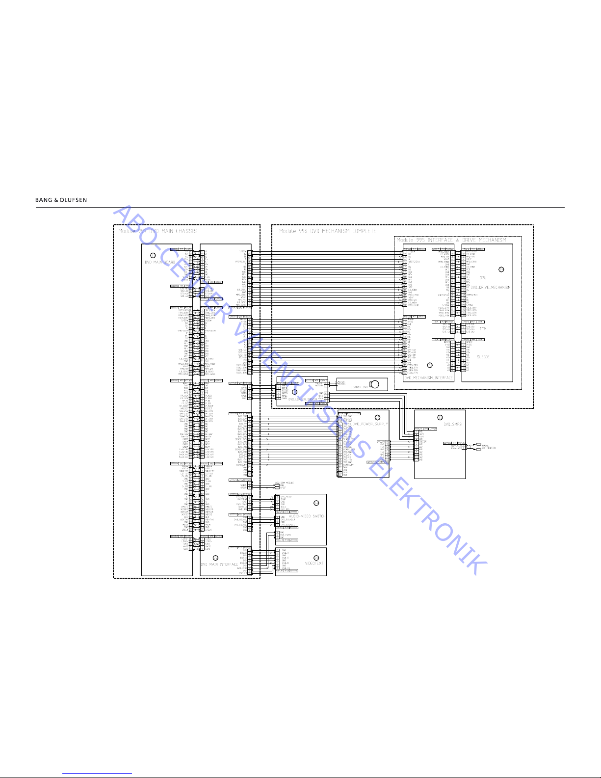
3.1 Wiring diagramWiring diagram 3.13.1
Wiring diagram
1010
1009
6200243
6200243 6200243
ABO-CENTER v/HENRIKSENS ELEKTRONIK
3.2 Wiring diagramWiring diagram 3.2 3.2
Wiring diagram
ABO-CENTER v/HENRIKSENS ELEKTRONIK
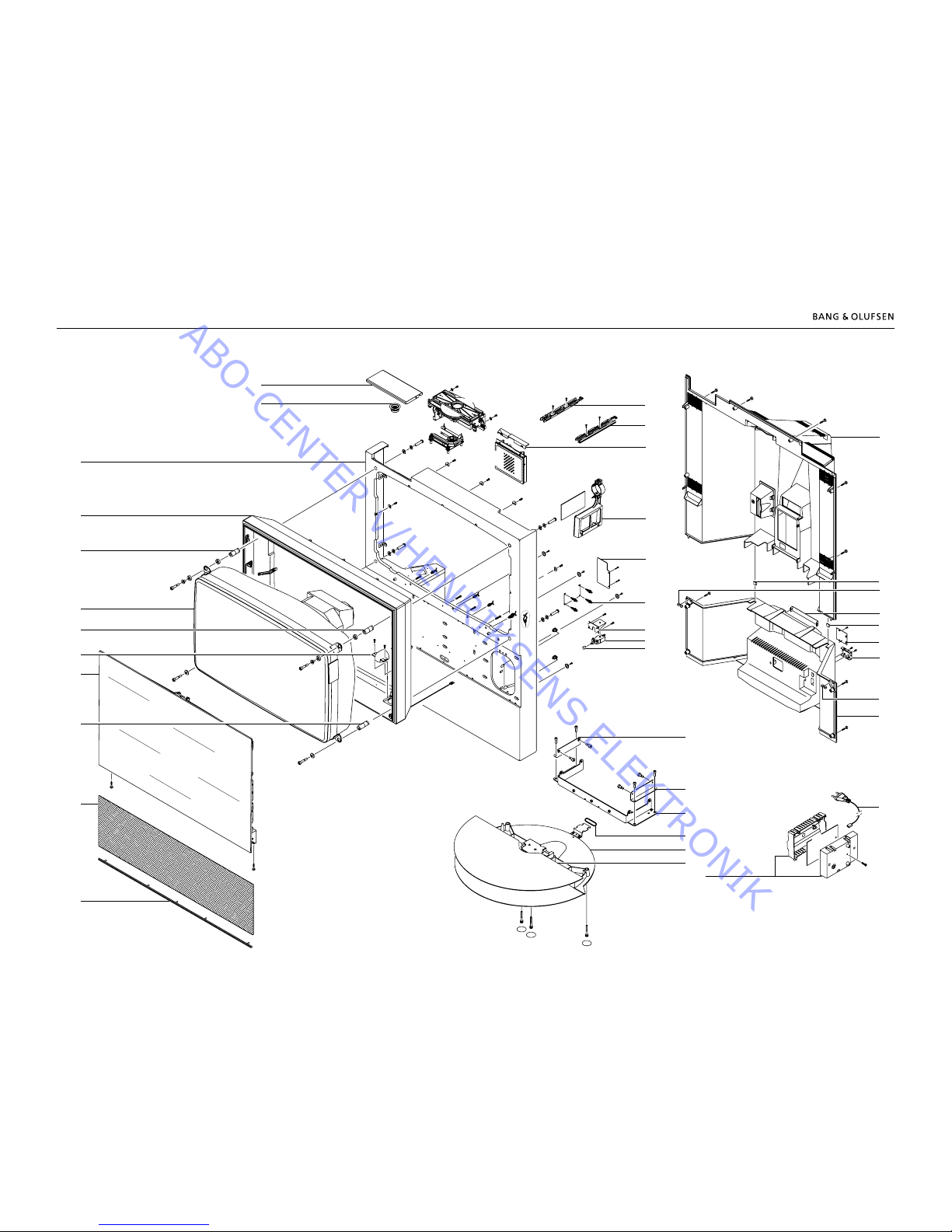
4.1 Available partsAvailable parts 4.14.1
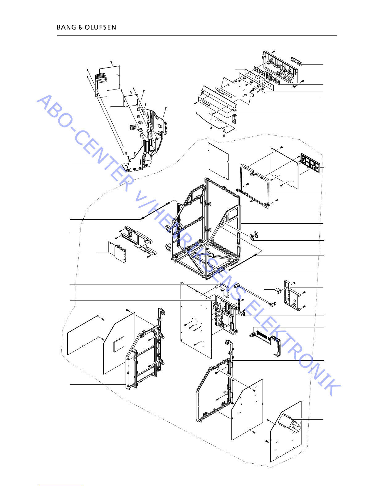
Available parts
Cabinet
9034
9026
9037
9037
9041
9040
9026
9039
9042
9032
9031
9033
9011
9089
9012
23
24
23
24
23
24
See also page 4.7
22
22
22
22
22
22
22
22
9023
W9
60
29
21
21
21
21
21
21
21
21
25
25
See also page 4.5
25
21
9019
9010
9013
21
9024
90S1
9025
18
7
6
5
9
5
9
17
17
20
13
15
13
15
13
15
9017
6
7
8
7
8
6
7
8
5
9
5
9
5
9
10
10
11
11
11
12
12
20
5
5
9015
9016
9018
9020
9020
9030
10
13
15
75
9028
29
Incl. pos. no. 9028
9027
29
29
9
9014
8
1
2
4
1
3
4
4
1
3
4
1
2
9021
9022
9046
9044
17
17
17
17
Incl. pos. no. 9022
and 995 Module
16
47
16
47
996
995
997
9047
ABO-CENTER v/HENRIKSENS ELEKTRONIK
Cabinet
4.2 Available partsAvailable parts 4.2 4.2
9010 3320488 Loudspeaker panel, silver
3320471 Loudspeaker panel, black
3320063 Loudspeaker panel, dark grey
3320066 Loudspeaker panel, light blue
9011 2732128 O-ring
9012 3458903 Base cover plate
9013 2569694 Prole, silver
2569693 Prole, black
2569010 Prole, dark grey
2569015 Prole, light blue
9014 3151620 Holder
9015* 3320629 Wall, silver - incl. pos. no. 9028
3320631 Wall, black - incl. pos. no. 9028
3320187 Wall, dark grey - incl. pos. no. 9028
3320188 Wall, light blue - incl. pos. no. 9028
9016 3320513 Frame
9017 3151682 Holder f/picture tube
9018 8200126 Picture tube
9019 3451698 Antireex coated contrast screen
9020 3151377 Holder f/picture tube
9021 3131471 Top cover
9022 3151646 Clamper
9023 3151623 Holder and lid f/PCB60
9024 3151490 Holder f/main switch
9025 2776517 Push button f/main switch
9026 2953007 Guide rail f/back cover
9027 3302622 Screen
9028 3151700 Spacer
9030 3162574
Cover f/main switch
9031 3152950 Holder
9032 3152950 Holder
9033 3454871 Frame
9034 3431324 Back cover, upper
9037 2953005 Guide rail f/back cover
9039 3152957 Cable holder
9040 3162721 Holder f/scart plug
9041 3152958 Cable holder
9042 3430803 Back cover, lower
9044 3152964 Guide rail, left
9046 3152963 Guide rail, right
9047 3162059 Cover f/sockets
9089 8053417 Motorized base plate, complete
90S1
7450100 Main switch
W9 6100325 Mains lead w/lter
6100404 Mains lead GB
6100248 Mains lead AUS
6100037 Mains lead CN
09Module 8005417 PCB9, Earth Field Compensation
60Module 8000309 PCB60, Mains Distribution
75Module 8000638 PCB75, DVD SMPS
995Module 8053039 DVD, Interface & Drive mechanism
996Module 8053037 DVD Mechanism incl. pos. nos. 9022 and 995Module
997Module 8053038 DVD main chassis
Survey of screws etc.
1 2076013 Screw
2 2622498 Washer
3 3937082 Bushing
4 2930121 Rubber bushing
5 2019021 Screw 4 x 12mm
6 2058024 Screw 8 x 35mm
7 2624074 Washer
8 2622555 Washer
9 2627023 Washer
10 2052005 Screw 4 x 25mm
11 3152827 Wire holder
12 3151497 Wire holder
13 2038103 Screw 3 x 12mm
15 2622530 Washer
16 2624067 Washer
17 2015156 Screw 3.5 x 12mm
18 2058054
Screw 8 x 30mm
20 3152952 Holder
21 2052002 Screw 50 x 27mm
22 2046039 Screw 6 x 18mm
23 2046037 Screw 6 x 40mm
24 3947565 Wafer
25 2013137 Screw 3 x 10mm
29 2015163 Screw 4 x 20mm
47 2042074 Screw 4 x 8mm
* Lacquer code nos.
for Wall pos. no. 9015
Colour: Silver
Colour code: Dupont AB BO941
Lacquer: Centari 600
Tone Colour 1 litre
AM 13 242.6
AM 7 281.6
AM 15 313.0
AM 90 315.6
AM 5 325.6
AB 150 966.0
Colour: Black
Colour code: Dupont AB HO697
Lacquer: Centari 600
Tone Colour 1 litre
AM 5 127.3
AM 73 144.9
AB 150 552.9
AB 160 928.2
Colour: Light blue
Colour code: Dupont XBBO 0224
Lacquer: Centari 600
Tone colour 1 litre
AM 73 422.1
AM 7 454.5
AM 1 471.8
AM 29 480.2
AM 64 488.0
XB 155 1006.6
Colour: Dark grey
Colour code: Dupont XBBO 0701
Lacquer:
Centari 6000
Tone Colour 1 litre
AM 2 178.4
AM 6 165.4
AM 73 118.4
AM 82 195.3
AM 84 187.1
XB 155 423.3
XB 165 952.7
symbol of safety component, see page 3.1
ABO-CENTER v/HENRIKSENS ELEKTRONIK
El-chassis
4.3 List of available partsList of available parts 4.34.3
9035 3151689 Holder f/PCB10
9060 3162804 Cover f/display
9061 3160072 Cover f/camcorder
9062 2776398 Set of buttons
9063 2572049 Spacer
9064 3131443 House f/display
9065 3152992 Service strap
9066 3152970 Holder f/PCB’s
9068 3151675 Wire holder
9069 3320240 Frame f/chassis
9071 3152992 Service strap
9074 3151731 Holder
9075 3031556 Ground spring
9076 3152969 Holder f/PCB4 and PCB5
W60 6270728 Coax cable SAT 230mm
01Module 8000149 PCB1, Tuner/IF & Nicam B/G
8000150 PCB1, Tuner/IF & Nicam B/GL/L’/I/D/K
8000151 PCB1, Tuner/IF & Nicam B/G/M/I/D/K/L
02Module 8000270 PCB2, Video/Chroma (incl. PCB7)
03Module 8000297 PCB3, Video Output
04Module 8000298 PCB4, Main Power Supply
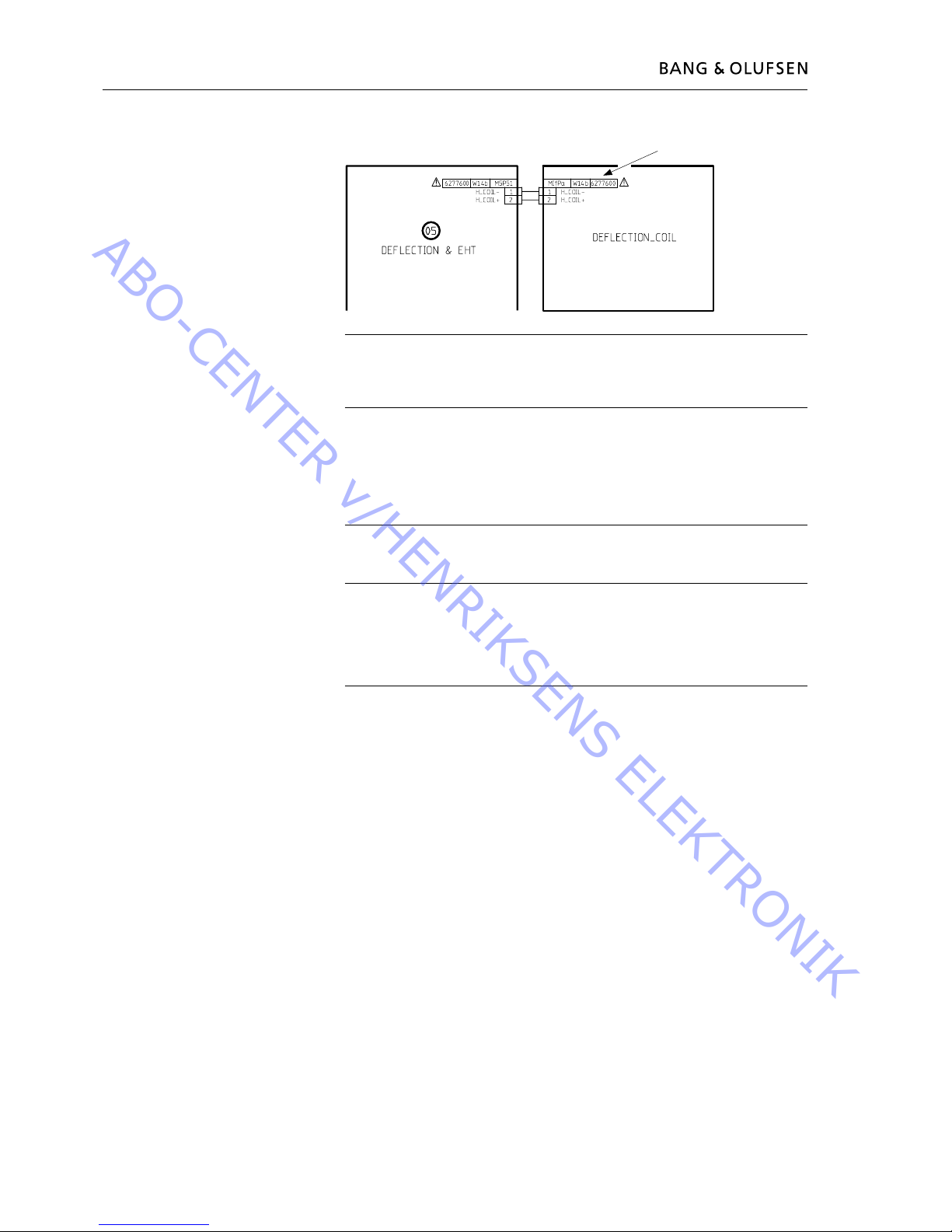
05Module 8000919 PCB5, Deection & EHT
5T1 8014235 EHT transformer incl. EHT cable and transformer
(Focus potentiometer is build into the transformer)
06Module PCB6, Main Microcomputer
6IC3*∆ 8344288 Software EPROM
6IC6∆ 8343984 EEPROM
07Module 8000302
PCB7, Teletext
10Module 8000631 PCB10, Sound Output
14Module 8000256 PCB14, AV Switch (incl. PCB6)
1402 3162339 Lid f/PCB6
1403 3151730 Holder
32Module 8000910 PCB32, AC3 with DTS
32IC607 8344177 Software AC3-DTS
3201 3151572 Holder
3202 3151570 Holder f/PCB32
57Module 8008372 PCB57, Operation Panel
58Module 8000633 PCB58, Display & IR
58DP2 8330346 LED display
59Module 8008855 Camcorder Interface & Headphone
61Module 8005946 PCB61, STB Controller (incl. PCB85)
6101 3151423 Holder f/PCB61
63Module 8000874 PCB63, Modulator B/G
8000873 PCB63, Modulator I
W35 6270739 Coax cable
74Module 8001225 PCB74, DVD Power Supply
85Module 8008922 PCB85, Minijack f/STB Controller
Screws etc.
* specially selected or adapted sample
∆ indicates that static electricity may destroy
the component
Chassis module 999 & back-up suitcases
Markets Type Chassis Back-up
module 999 suitcase
A-B-CH-D-DK-E-GR-N- B/G with B/G modulator 8053020 3395235
NL-P-S-SF-I-NZ-AUS
UK B/G/L/L’/I/D/K with I modulator 8053021 3395236
EEU-HUN-Thailand B/G/M/I/D/K/L with B/G modulator 8053023 3395238
HK-CN B/G/M/I/D/K/L with I modulator 8053024 3395239
F-CH-B-Channel Islands B/G/L/L’/I/D/K with B/G modulator 8053022 3395237
Display & IR
PCB57-PCB58-PCB59
3131480 Display & IR
25 2013137 Screw 3 x 10mm
35 2052010 Screw 50 x 12mm
36 2013153 Screw 3 x 6mm
37 2013220 Screw 2.5 x 10mm
38 2380145 Nut f/mini jack socket
39 2013147 Screw 3 x 5mm
58 2052032 Screw 4 x 16mm
ABO-CENTER v/HENRIKSENS ELEKTRONIK
Available parts 4.4
El-chassis
85
7
1
2
4
5
9066
W60
9074
9076
57
58
59
9060
9064
58DP2
9063
9062
9061
35
35
36
36
36
36
36
36
36
36
37
37
9069
61
9065
9071
9068
6101
25
25
25
25
25
25
38
63
14
6
1402
1403
W35
9075
39
39
25
25
25
25
25
25
25
25
25
25
25
25
25
25
25
5T1
25
25
25
25
25
25
25
25
74
10
9035
58
58
58
999Module
32
3201
25
25
25
25
25
25
3202
3
ABO-CENTER v/HENRIKSENS ELEKTRONIK

4.5 Available parts
Picture tube
9018 8200126 Picture tube
9050 6850225 Compensation coil
9053 3152752 Holder f/degaussing coil
9054 7510053 Ground current
9055 3151673 Holder f/degaussing coil
9056 8022374 Degaussing coil
9057 3152178 Wire holder
9059 3152185 Wire holder
5T1 8014235 EHT transformer incl. EHT cable and transformer
(Focus potentiometer is build into the transformer)
9053
9053
9054
9055
9018
9056
9057
9053
5T1
9059
9053
9050
ABO-CENTER v/HENRIKSENS ELEKTRONIK
Available parts 4.6
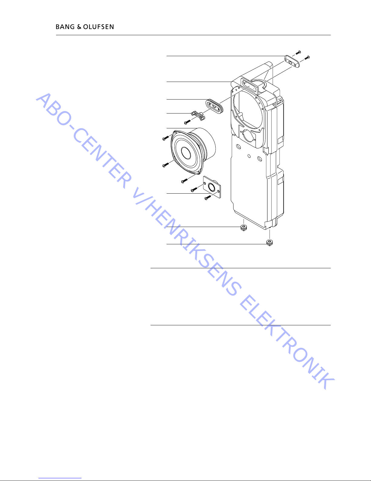
Sound
9080 3152979 Holder
9081 3430734 Loudspeaker cabinet, left
3430735 Loudspeaker cabinet, right
9082 3333031 Gasket
9083 3152980 Holder
9084 8480261 Bass speaker 4.5”- 8Ω
9085 8480237 Treble speaker 18mm - 8Ω
9086 3333033 Rubber bushing
9087 3333033 Rubber bushing
RIGHT
9080
9086
9085
9084
9083
9081
9082
9087
46
46
29
46
46
46
46
46
Survey of screws
29 2015163 Screw 4 x 20mm
46 2019018 Screw 4 x 16mm
ABO-CENTER v/HENRIKSENS ELEKTRONIK
4.7 Available parts
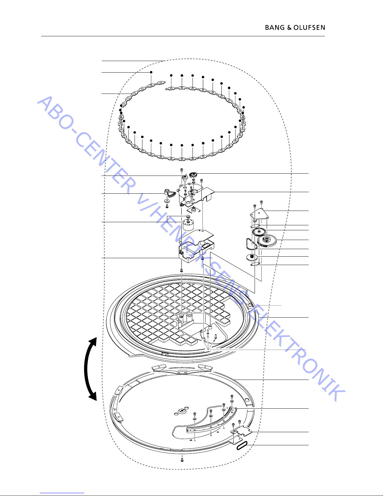
81
80
Cage f. ball bearing
9090
9092
9093
90M1
9094
9091
9095
9099
9098
9097
9096
90103
90102
90101
90100
90104
Shafts
90105
9011
90107
90106
47
47
49
48
51
50
55
52
47
47
47
47
47
47
54
53
54
53
54
53
54
53
53
53
Incl. pos. nos. 9011,
90106, 90107
9089
Motorized base plate
ABO-CENTER v/HENRIKSENS ELEKTRONIK
Available parts 4.8
Motorized base plate
LUBRICATION
Cage for ball bearing 3984057
Full synthetic grease (50g)
Tooths on gear wheel rim 90106 3984049
Barrierta grease L55/3 (25g)
Full periphery of gear wheels 9099 and 90100
Rim of gear wheel 9093
Shafts on 90104 3984051
Barrierta oil IS Fluid (50ml)
9011 2732128 O-Ring
9089 8053417 Motorized base plate, complete
9090 2917030 Ball
9091 3152942 Holder
9092 2993038 Centre tap
9093 2700128 Gear wheel
9094 3162464 Cover w/plate
9095 2700129 Gear wheel
9096 3152940 Holder f/motor
9097 3152941 Holder f/gear wheel
9098 3472827 Damper f/gear wheel
9099 2700131 Gear wheel
90100 2700132 Gear wheel
90101 2732092 Belt
90102 2700130 Gear wheel f/belt
90103 3472827 Damper f/gear wheel
90104 2752035 Top plate
90105 3454810 Bottom plate
90106 2700133 Gear wheel rim
90107 3152959 Holder f/wire bundle
90M1 8400210 Motor
80Modul 8008337 PCB80, Motor Stand Control
81Modul 8008338 PCB81, Motor Stand
Survey of screws etc.
47 2042074 Screw 4 x 8mm
48 2380165 Nut
49 2622500 Washer
50 2036061
Screw 2.6 x 6.5mm
51 2938306 Rubber bushing
52 2930074 Bushing
53 2042073 Screw 4 x 6mm
54 2622467 Washer
55 2622492 Washer
ABO-CENTER v/HENRIKSENS ELEKTRONIK
4.9 Available parts
Wire bundles
See wiring diagram page 3.1 and 3.2.
The part no. is printed on the diagram above the wire bundle, as shown.
Accessories
See page 1.6.
Parts not shown
3390621 3 holders for scart plugs, screws and extension straps for repacking
6780000 Test tape
3629145 IC-pliers
3634060 Tool f/picture tube replacement
3657448 Product cover
3658260 Trolley
ServiceTool
3658964 ServiceTool CD-ROM
3375397 Cable kit for ServiceTool, complete
Available documentation
3543421 On-site service guide
English, German, French, Italian, Spanish, Danish, Dutch
Guides and Reference Book, see Retail Ordering System
ABO-CENTER v/HENRIKSENS ELEKTRONIK
Packing
9301 3392549 Outer carton, top
9302 3396008 Foam packing, set of top and bottom
9303 3917105 Foam foil - 1200 x 600mm
9304 3392550 Outer carton, side
9305 3392555 Masonite - order 2pcs. (AUS-HK-CN)
9306 3917105 Foam foil - 1200 x 600mm
9307 3392549 Outer carton, bottom
9308 3392679 Wooden pallet
3392551 Wooden pallet (AUS-CN)
9309 3392699 Chip board (AUS)
9310 3392550 Outer carton, side
9311 3392556 Masonite - order 2pcs. (AUS-HK-CN)
3946176 Bag w/15m strap and 3 holders
9301
9302
9302
9306
9305
9304
9303
9308
9307
9311
9310
9309
Available parts 4.10
ABO-CENTER v/HENRIKSENS ELEKTRONIK

4.11
ABO-CENTER v/HENRIKSENS ELEKTRONIK
Adjustments, English 5.1
Adjustments
Reset
Set brilliance, colour saturation and contrast to nominal values so that they can be
recalled by means of RESET (perhaps an ADD function).
- Press TV MENU SETUP PICTURE
Brilliance Colour Contrast
32 32 44
- Adjust by means of
l, n, m or p, and back up with STOP. Values can be stored by
means of GO.
Format
BeoVision Avant 32 DVD provides the opportunity to choose from three different
picture formats by means of the Beo4 remote control.
Format 1: For standard 4:3 TV pictures. Two views are available: 15:9, 16:9
panoramic. Press
m or p to toggle between the two views.
Format 2: Letter box formats, the Format Optimize circuit chooses the optimal
format. It is possible to move the picture up or down by pressing
m or p.
Format 3: 16:9 wide screen. Format 3 will usually be selected automatically, but it
can be selected manual.
“Picture adjustments” only have to be made in format 1 (15:9).
“Geometry adjustments” have to be made in format 3 (16:9) and format 1 (15:9
+ 4:3).
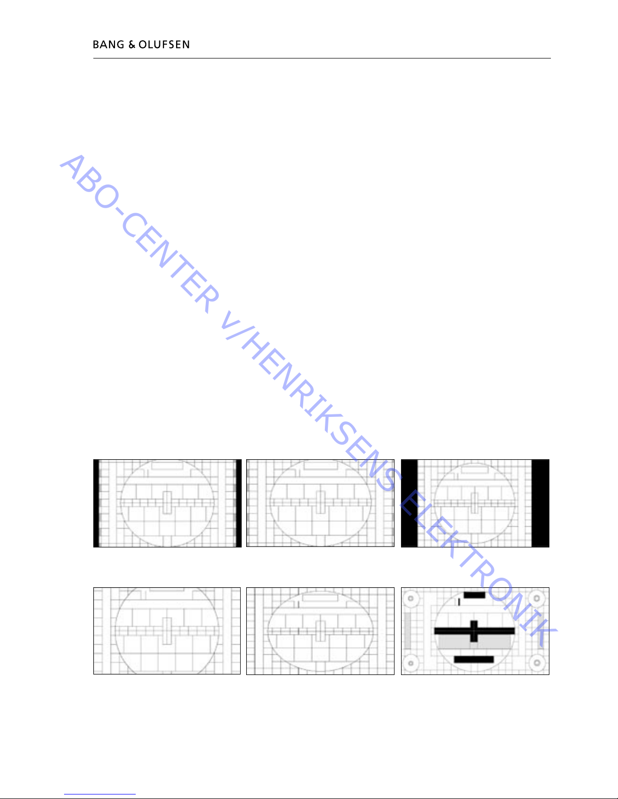
Selecting a format:
Press TV and toggle the LIST key until the Beo4 display reads FORMAT, then press
1, 2 or 3 to select a format.
Format 1 (15:9) Format 1 (16:9 panorama) Format 1 (4:3)
Format 2 (Letterbox) Format 3 (4:3) Format 3 (16:9)
ABO-CENTER v/HENRIKSENS ELEKTRONIK

5.2 Adjustments, English
Adjustments, English 5.3
Illustrations for:
- Adjustments, see page 5.121 Measurements
- Geometry parameters, see page 5.122
- Geometry measuring points, see page 5.123
All measurement concerning the geometry is measured without the contrast
screen mounted.
Measurements are performed with a ruler directly on the picture tube.
All measurements are measured from the phosphors edge, unless other is
specied.
For the best result, measurements are performed in a straight viewing angle to the
picture tube, e.g. you see into the reection of your own eye.
Geometry must be checked and adjusted in format
16:9, FORMAT 3
15:9, FORMAT 1
4:3, FORMAT 1 + scroll (optional format)
(3 different set of adjustment data is stored)
The picture tube and the contrast screen must be cleaned after geometry adjustment.
- How to enter Geometry adjustment
Service mode
Menu – Setup - 0 0 GO - Geometry adjustment
Arrow up/down step in menu
GO, select item in menu
Arrow up/down = adjust value
Arrow right/left = step up/down in menu
- Test tape 6780000, contains test pictures that are referred in the adjustment
procedure.
First 15 min. 16:9
Last 15 min. 4:3
Other test pictures may be used.
- Preparations before Geometry checking and adjustment.
1. Dismount Contrast screen
2. Cover the Auto contrast
3. Turn TV on
4. Select the correct test picture “Philips test picture”
5. In Service mode – Format setting
Geometry lock : OFF
4:3 : YES
6. Set TV into FORMAT 3, 16:9
ABO-CENTER v/HENRIKSENS ELEKTRONIK
Adjustments, English 5.3
- Adjustment procedure.
1. Horizontal center adjustment
2. G2-adjustment
3. Focus adjustment
4. EFC adjustment
5. 16:9 adjustment
6. 15:9 adjustment
7. In Service mode – Format setting
Geometry lock : OFF
4:3 : YES
8. 4:3 adjustment
- Finishing Geometry checking and adjustment.
1. Clean the picture tube
2. Clean the contrast screen
3. Remount the contrast screen
Initial settings in order to adjust the TV
The upper back cover should not be mounted before adjustment is completed.
- Connect the mains voltage and switch on the TV.
- Remove all the Scart plugs in the scart sockets, if any is connected.
Enter SETUP and select CONNECTIONS.
Set V.TAPE to V.TAPE.
Press GO and then EXIT to leave the menu.
It might be necessary to pull the Main chassis partly out of the main frame in
order to get access to the Focus and G2 potentiometer.
Horizontal center adjust
Horizontal center switch 5S1 must be adjusted to the position left, center or right.
See 1.
Press V.TAPE.
The screen should go black.
Set the TV is in format 3, 16:9, press LIST (until FORMAT) + 3
Adjust the G2, SCREEN, potentiometer until the background is clearly lit up.
See 2.
Reduce H-AM until the picture is smaller than the prosper frame, app. 10 mm on
each side.
Enter Service menu
Menu – Setup - 0 0 GO - Geometry adjustment
Select H-AM GO. Make a note of the value.
Adjust with 5S1 for best center position, ensure that the switch rests in the “click”
and not between two positions.
Reset H-AM to previous value.
Press GO, to store value.
Press EXIT, to leave service menu.
ABO-CENTER v/HENRIKSENS ELEKTRONIK
5.4 Adjustments, English
Adjustments, English 5.5
G2 (cut off) adjustment
TV mode V.TAPE
Format 16:9, Format 3
Test picture Black or no source connected.
Menu setup
Picture – Brilliance 32, Colour 32, Contrast 44
Service Menu setup
Not used
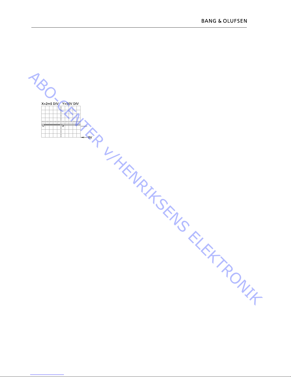
- Measurement with an oscilloscope.
Connect oscilloscope ground to GROUND on PCB3, see 3.
Measure the level of the test puls on the test points R, G and B, see 3.
Select the measuring point with the highest level and adjust by means of G2 until
the puls is 145 ± 3V.
- Adjust with a multi-meter (Ri > 1 Mohm).
Set the multi-meter in a DC-voltage area of minimum 200V.
Connect the ground probe on the ground on PCB3, see 3.
Measure the voltage level on the test points R, G and B, see 3.
Notice the measuring point with the highest voltage level and place the measuring
probe on this point.
Select the measuring point with the highest level and adjust by means of G2 until
the voltage level is app. 167V.
Focus adjustment
TV mode V.TAPE
Format 16:9, Format 3
Test picture Test picture 16:9
Menu setup
Picture – Brilliance 32, Colour 32, Contrast 44
Service Menu setup
Not used
Connect external VTR to the TV.
Use test tape, 6780000.
Press V.TAPE
Cover the display panel e.g. with a soft cloth to prevent back light adjusting the
contrast.
Adjust FOCUS 1, Vertical line no 2 in the right side.
Adjust FOCUS 2, Horizontal line no 3 from the top.
Repeat vertical and horizontal adjustment minimum twice, always ending with
horizontal, FOCUS 2, see 2.
145V
ABO-CENTER v/HENRIKSENS ELEKTRONIK
Adjustments, English 5.5
Earth eld correction
Earth eld correction must be performed before geometry adjustment.
TV mode V.TAPE
Format 16:9, Format 3
Test picture Test picture 16:9
Menu setup
Picture – Brilliance 32, Colour 32, Contrast 44
Service Menu setup
Menu – Setup - 0 0 GO - Earth eld correction
Compensation ON
Connect external VTR to the TV.
Use test tape, 6780000.
Press V.TAPE
Adjust TOP SKEW until A1B1 = C1D1, top line straight.
Adjust BOTTOM SKEW until A2B2 = C2D2, bottom line straight.
Exit Service mode, Press EXIT.
Geometry in FORMAT 3, 16:9
TV mode V.TAPE
Format 16:9, Format 3
Test picture Test picture 16:9
Menu setup
Picture – Brilliance 32, Colour 32, Contrast 44
Service Menu setup
Menu – Setup - 0 0 GO - Geometry adjustment
Connect external VTR to the TV.
Use test tape, 6780000.
Press V.TAPE
1. V-PS, Vertical S-correction
Set V-PS = 18, default value.
2. V-SH, Vertical Shift
Set Blanking ON
Adjust V-SH until blanking is covering up to the vertical center ± 1 mm
App. 187mm from top/bottom of phosphor edge.
Set Blanking OFF
3. V-OL, Vertical Scroll
Set V-OL = 31, default value in 16:9
4. V-AM, Vertical Amplitude
Adjust distance E to I = 10 ± 1.5 mm
ABO-CENTER v/HENRIKSENS ELEKTRONIK

5.6 Adjustments, English
Adjustments, English 5.7
5. V-SL, Vertical Slope
Adjust distance N to G = 10 ± 1.5 mm
6. H-PH, Horizontal Phase
Adjust distance H to Q = distance T to F within ± 2mm
7. H-AM, Horizontal Amplitude
Adjust distance H to Q = distance T to F = 20 ± 2.5mm
EW adjustments might have to be performed more than one time in order to
obtain the optimum result.
8. EW-PA, EW Parable
(attention to middle 2/3 of line)
VERTICAL line LEFT (one square in) as straight as possible
VERTICAL line RIGHT (one square in) as straight as possible
9. EW-UC, EW Upper Corner
(attention to upper compared to middle 2/3)
VERTICAL line LEFT (one square in) as straight as possible
VERTICAL line RIGHT (one square in) as straight as possible
10. EW-LC, EW Lower Corner
(attention to lower compared to middle 2/3)
VERTICAL line LEFT (one square in) as straight as possible
VERTICAL line RIGHT (one square in) as straight as possible
11. EW-TZ, EW Trapez
Adjust HORIZONTAL distance between
top : left and right (one square in + one square down) equals
bottom : left and right (one square in + one square up)
12. EW-PG, EW Parallelogram
Adjust distance in top and bottom (left and right)
top : left (one square in and one square down)
=
bottom left (one square in + one square up)
top : right (one square in and one square down)
=
bottom right (one square in + one square up)
13. BOW, Horizontal Bow
Adjust (attention to hole line)
VERTICAL line LEFT (one square in) as straight as possible
VERTICAL line RIGHT (one square in) as straight as possible
Geometry in FORMAT 1, 15:9
TV mode V.TAPE
Format 15:9, Format 1
Test picture Test picture 4:3
Menu setup
Picture – Brilliance 32, Colour 32, Contrast 44
ABO-CENTER v/HENRIKSENS ELEKTRONIK
 Loading...