

Page 1
BeoVision 7
Page 2

Page 3

Dear Customer
This Getting Started contains information about the daily use of your Bang&
Olufsen product and connected equipment. We expect your retailer to deliver,
install and set up your product.
Your television offers more features and functions than described in this Getting
Started. Among other things; Timer functions and auto standby, editing and
naming channels. These and other features are described in more detail in the
product’s Guide.
The Guides are found on www.bang-olufsen.com/guides.
The Guides are also kept up to date if new software introduces new or modied
features and functions in your television.
On www.bang-olufsen.com you can also nd further information and relevant
FAQs about your product.
Your Bang& Olufsen retailer is your rst stop for all your service queries.
To nd your nearest retailer, visit our website…
www.bang-olufsen.com
Technical specications, features and the use
thereof are subject to change without notice.
3510584 1007
Page 4
WARNING: To reduce the risk of fire or
electric shock, do not expose this
appliance to rain or moisture. Do not
expose this equip ment to dripping or
splashing and ensure that no objects
filled with liquids, such as vases, are
placed on the equipment.
To completely disconnect this equipment
from the AC Mains, disconnect the mains
plug from the wall socket. The disconnect
device shall remain readily operable.
The lightning flash with arrowhead
symbol within an equilateral triangle,
is intended to alert the user to the
presence of un insulated “dangerous
voltage” within the product’s enclosure that may be of sufficient
magnitude to constitute a risk of
electric shock to persons.
The exclamation point within an equi-
lateral triangle is intended to alert the
user to the presence of important
operating and main tenance (servicing)
instructions in the literature
accompanying the product.
Read these instructions.
Keep these instructions.
Heed all warnings.
Follow all instructions.
Do not use this apparatus near water.
Clean only with dr y cloth.
Do not block any ventilation openings. Install in
accordance with the manufacturer’s instructions.
Do not install near any heat sources such as
radiators, heat registers, stoves, or other
apparatus (including ampliers) that produce heat.
Do not defeat the safety purpose of the polarized
or grounding-type plug. A polarized plug has two
blades with one wider than the other. A
grounding type plug has two blades and a third
grounding prong. The wide blade or the third
prong are provided for your safety. If the provided
plug does not t into your outlet, consult an
electrician for replacement of the obsolete outlet.
Protect the power cord from being walked on or
pinched particularly at plugs, convenience
receptacles, and the point where they exit from
the apparatus.
Only use attachments/accessories specied by the
manufacturer.
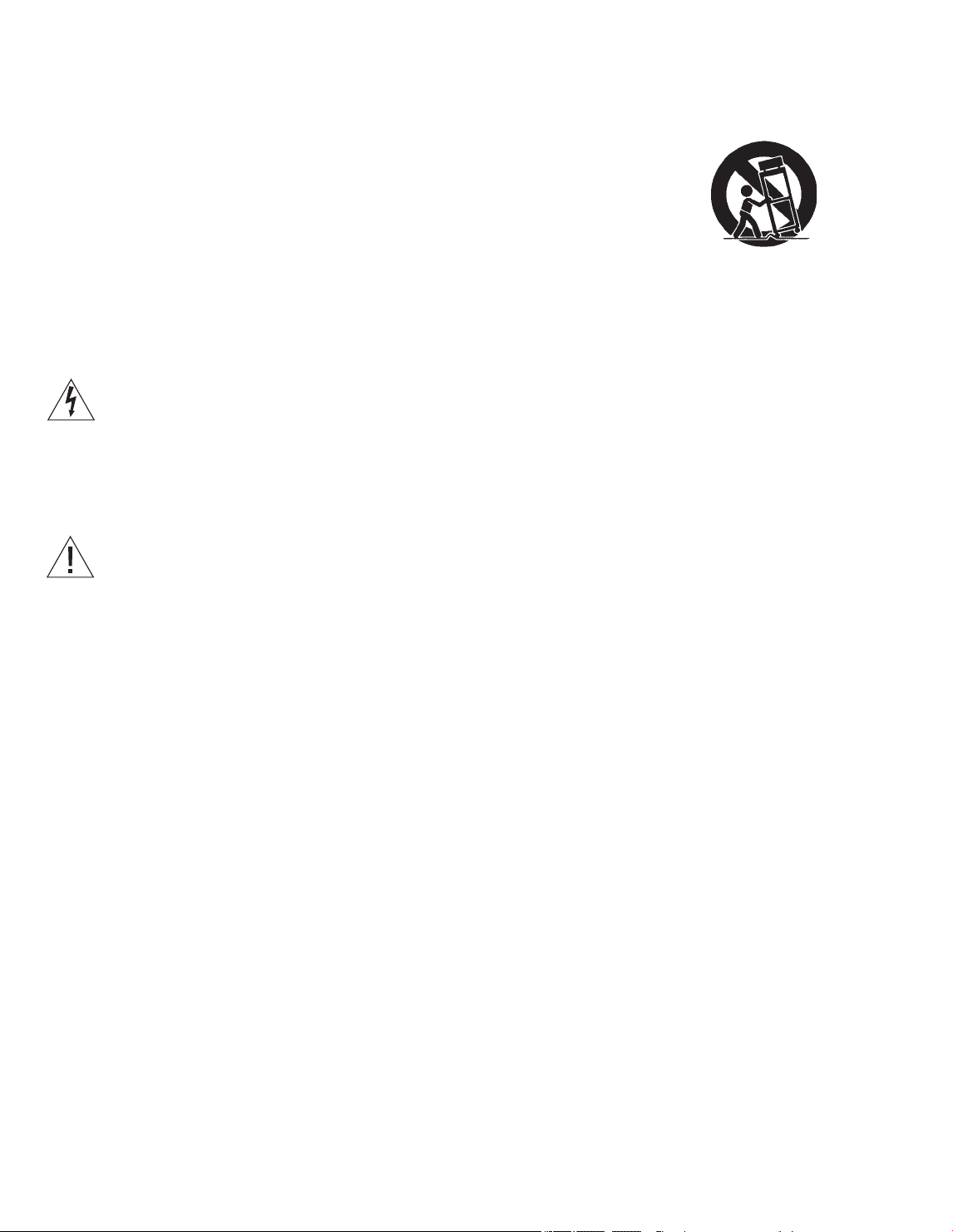
Use only with the cart, stand, tripod, bracket, or
table specied by the manufacturer, or sold with
the apparatus. When a cart is used, use caution
when moving the cart /apparatus combination to
avoid injury from tip-over.
Unplug this apparatus during lightning storms or
when unused for long periods of time.
Refer all servicing to qualied service personnel.
Servicing is required when the apparatus has been
damaged in any way, such as power-supply cord
or plug is damaged, liquid has been spilled or
objects have fallen into the apparatus, the
apparatus has been exposed to rain or moisture,
does not ope rate normally, or has been dropped.
The mains plug of the power supply cord shall
remain readily operable.
Do not expose batteries or battery packs to
excessive heat such as sunshine, re or the like.
Follow instructions to ensure correct and safe
installation and interconnection of equipment in
multimedia systems.
Page 5

Contents
Daily use
6 How to use your remote control
8 Introduction
10 Watch television
12 Watch television via the digital tuner
14 Use the Blu-ray player
16 Change sound type and picture format
17 Use the Adaptive Sound Technology
Installation
20 Set up your television
21 Cleaning
22 Connection panels – BeoVision7–55
24 Connection panels – BeoVision7–40
26 First-time setup of your television
Cautions
– Ensure that the television is positioned, set up
and connected in accordance with the
instructions in this Getting Started. To prevent
injury, use Bang & Olufsen approved stands and
wall brackets only!
– Place your television on a rm, stable surface.
– Do not place any items on top of your television.
– Do not subject the television to rain, high
humidity or sources of heat.
– The television is developed for indoor use in dry,
domestic environments only. Use within a
temperature range of 50–105°F (10–40°C), and
at an altitude of no more than 5,000ft
(1,500m).
– Do not place the television in direct sunlight or
direct articial light, such as a spotlight, as this
may reduce the sensitivity of the remote control
receiver. Also if the screen is overheated, black
spots may appear in the picture. These spots
disappear again, once the television cools down
to normal temperature.
– Leave enough space around the television for
adequate ventilation.
– Connect all cables before connecting or
reconnecting any of the products in your system
to the mains.
– No naked ame sources, such as lighted candles
should be placed on the apparatus.
– Do not attempt to open the television. Leave
such operations to qualied service personnel.
– Do not strike the glass with hard or pointed
items.
– The television can only be switched off
completely by disconnecting it from the wall
socket.
– The disconnect device shall remain readily
operable.
– The supplied mains cord and plug are specially
designed for the television. If you change the
plug or in any way damage the mains cord, it
can affect the TV performance.
Daily use
Page 6
6
How to use your remote control
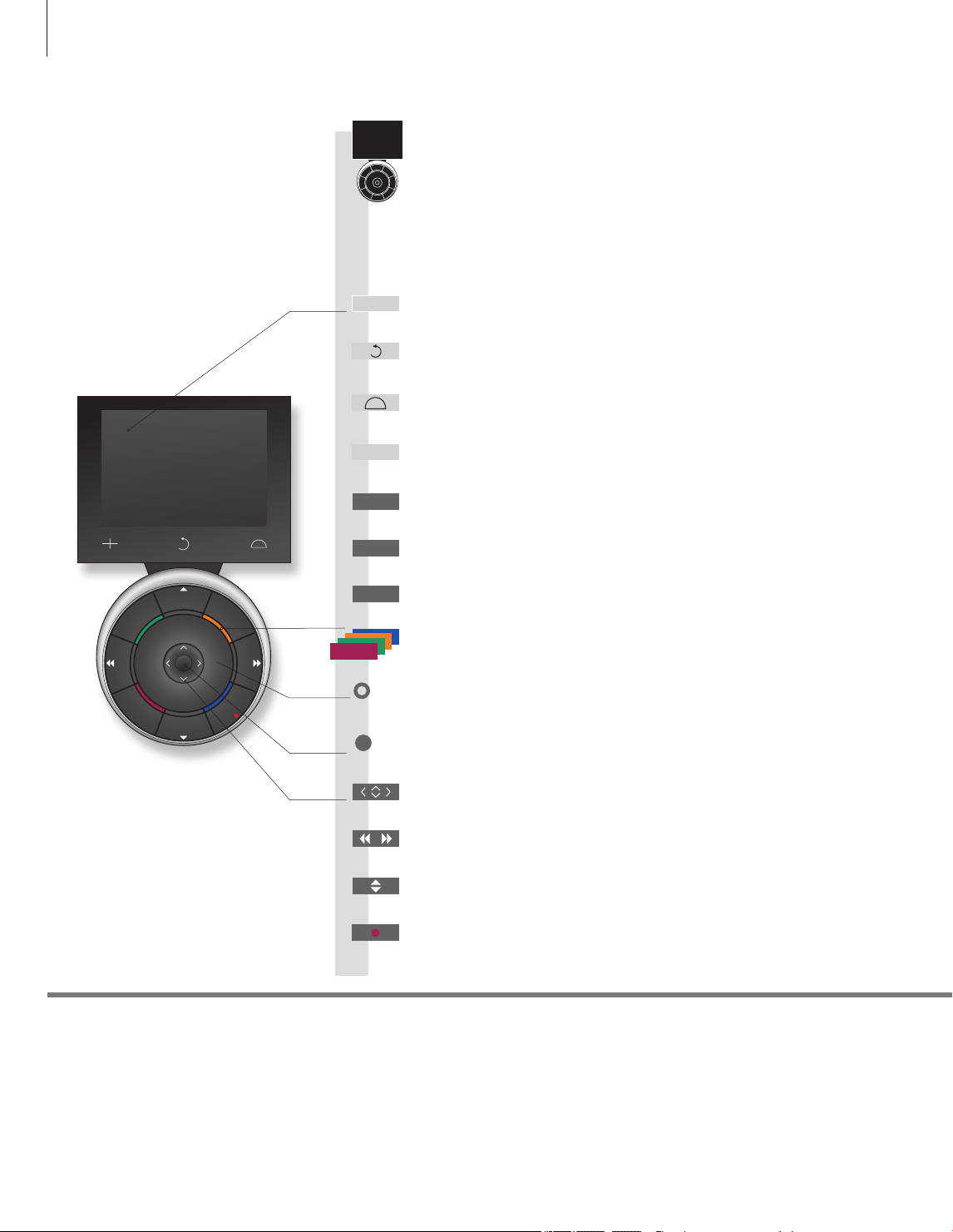
Beo5 operation
Your television can be operated with the Beo5 remote control.
Living Room
TV V.MEM RADIO
DTV N.MUSIC N.RADIO
PC DVD CD
STOP
BACK
PLAY
Soft button, touch screen to select*
TV
Switch on a source or select a function
Back up through Beo5 displays
Bring up SCENE buttons, such as Zones or Speaker
Press again to return
Bring up digits to select channel
+
Press again to return
Pause and stop playback or recording
STOP
Start playback of a disc or recording
PLAY
Move backwards through menus. Long press to exit menus completely
BACK
Select colour specic functions*2
Press volume wheel next to the colour
Turn to adjust volume
To mute, turn quickly counter-clockwise
Centre button is used for selecting and accepting
1
Important
Soft buttons on Beo5
– for more information: www.bang-olufsen.com
1*
About buttons
2*
Coloured buttons
Actual zone
Light grey buttons indicate that you have to press a text in the display. Dark grey buttons indicate that you have to
press a hard button.
Press the wheel next to the colour to activate a coloured button.
Indicates the actual zone on Beo5 as it was named during the setup process.
Depending on the activated source, different soft buttons appear on the screen. Touch the screen to activate the
function.
Navigation button left, right, up and down – move in menus by pressing the
button in the direction you need
Rewind or wind, search backwards or forwards
Step through channels or recordings
Hold for continuous step
Standby
Page 7
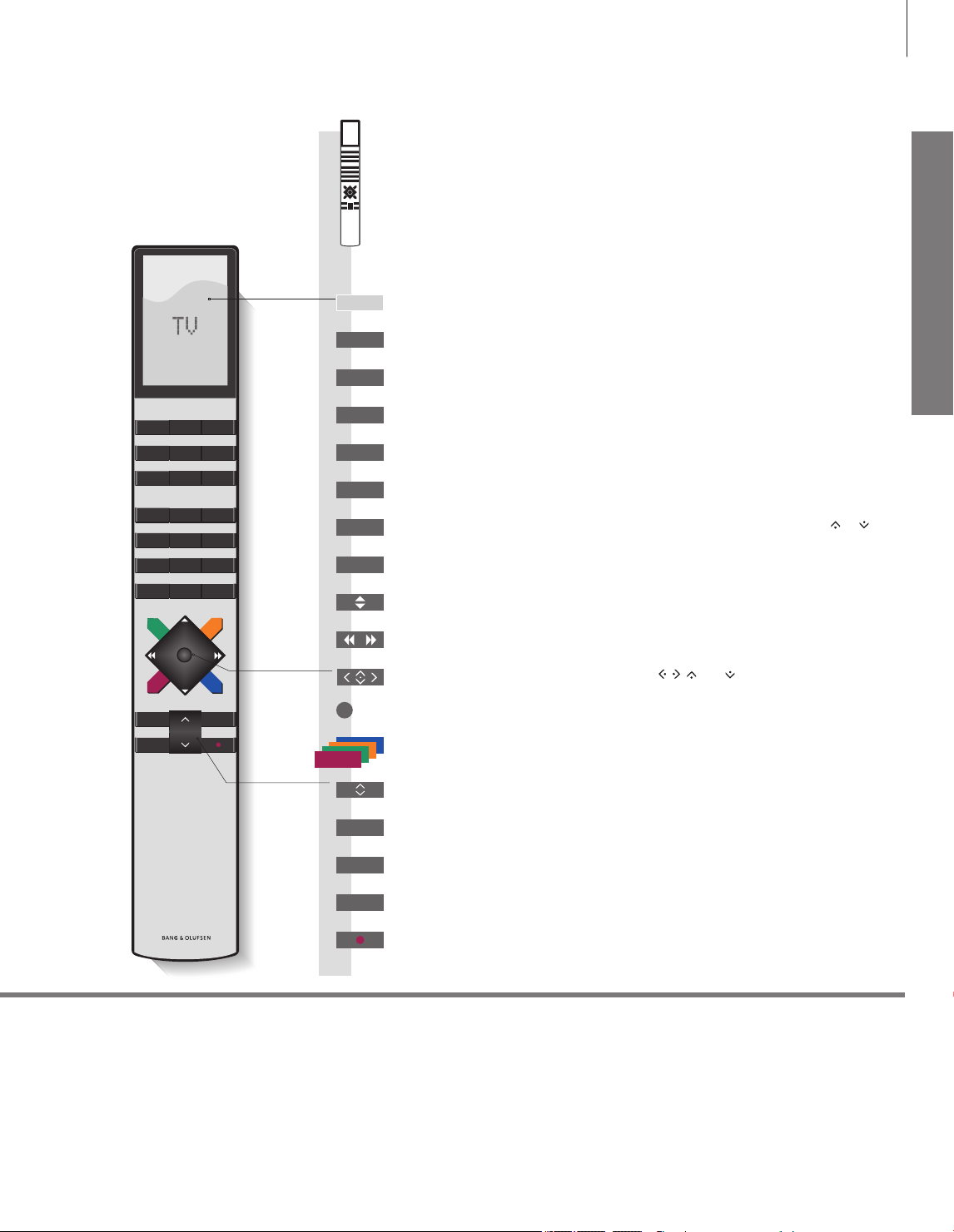
Beo4 operation
7
TV LIGHT RADIO
DTV DVD CD
V.MEM TEXT A.MEM
7 8 9
4 5 6
1 2 3
LIST
MENU
0
TV
TV
DTV
DVD
TEXT
0 – 9
LIST
MENU
You can also operate your television with a Beo4. When Beo4 operation is
different from Beo5 operation, it is described separately.
The Beo4 display shows you the activated source or function
3
Switch on the TV*
Switch on the digital tuner
Switch on the optional Blu-ray player
Activate Closed Captioning
Select channels and enter information in on-screen menus
Display extra “but tons” for functions or sources in the Beo4 display. Use
step in the list
Bring up the main menu of the active source
Step through channels
Hold for continuous step
Rewind or wind, search backwards or forwards
or to
Daily use
STOP PLAY
BACK
3*
Beo4 buttons
Navigation button left, right, up and down
, , and – move in menus by
pressing the button in the direction you need
Centre button is used for selecting and accepting
Select colour specic functions
Adjust volume
To mute, press the middle of the button
Pause and stop playback or recording
STOP
Start playback of a disc or recording
PLAY
Move backwards through menus and the Beo4 list. Long press to exit menus
BACK
completely
Standby
Some buttons can be recongured during the setup process. See the Guide for further information.
NOTE! For general information about remote control operation, see the guide enclosed with your remote
control.
Page 8

8
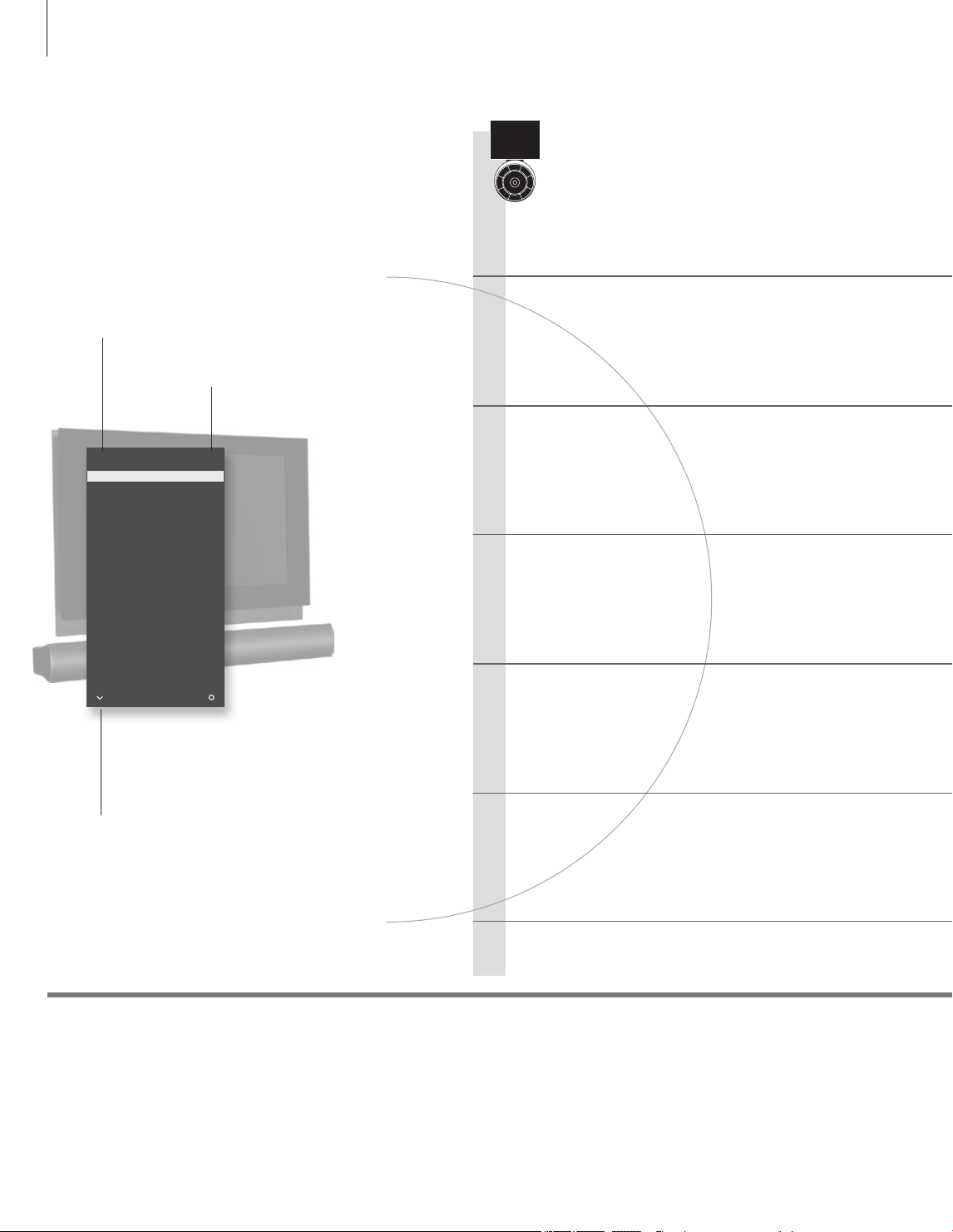
Introduction
Navigate in menus and select settings using your remote control. Pressing Menu
brings up the menu for the selected source.
Display and menus
Information about the selected source is shown in
the display window to the right. On-screen menus
allow you to adjust settings.
Menu name
Menu options
Information eld
… TV Menu
TV SETUP
CHA NNEL SETUP
SLE EP TIM ER
PLAY T IMER
OPT IONS
STAN D POS ITION S
sel ect
Example of on-screen menu
or
DVD
Switch on optional Blu-ray player
Show menu Select TV’s zone Switch on TV
Important
Remote control
On the rst pages in this Getting Started, you will nd an overview of the buttons on Beo5 and Beo4.
For general information about remote control operation, see the guide enclosed with your remote
control. This Getting Started and the Guide describe operation with the REMOTE CONTROL menu set to
NAVIGATION BUT TON and the remote control set to MODE1. Do not change MODE during rst-time
setup, as this will interrupt the sequence.
Page 9

9
Daily use
Navigate in menus
When a menu is on the screen, you can move
between menu options, reveal settings or enter
data.
Select option/
setting
0 – 9 BACK BACK
Enter data Bring up sub-
menu/store
setting
Select option Move
backwards
through menus
or
Press and hold to
exit menus
REMOTE CONTROL menu
In the OPTIONS menu, you can bring up the REMOTE CONTROL menu. In this menu you must set up
your television to be operated with or without a navigation button. Remember to set your Beo4 remote
control to the correct mode. See the Beo4 guide or contact your Bang& Olufsen retailer for further
information.
Page 10
10
Watch television
Choose a TV channel by its number or switch to another
channel. Adjust the sound volume and turn the TV.
Activate the TV source to use these functions
Channel name
Channel number
TV CHANN EL LI ST
CNN 1
… 2
DIS COVER 3
CWN BC 4
BBC WORLD 5
… 6
… 7
… 8
SUP ER CH 9
… 10
CRI ME TV 11
CIN EMA 12
… 13
MOVI E NW 14
… 15
… 16
… 17
… 18
mor e sele ct
Beo5 operation
Switch on the TV
Select a TV channel
Bring up a channel list
Adjust the volume
Indicates that more channels are
available
Useful hints
Turn the TV
If your television is equipped with a motorised stand, you can turn it
by means of the remote control
Switch off the TV
1
*TV positions Position1 is the far left position and Position9 is the far right. Position 5 is the centre position.
Page 11

Beo4 operation
11
Daily use
TV
Press
or
+
Select Activate
Hold for
channel list
Adjust volume. To mute, turn quickly
counter-clockwise
numbers
Select page Activate numbers Accept
0–9
Select channel
Select
channel
Select previous channel
or
+
Turn either way to bring back the sound
0–9
TV
Press
Select
Hold for
channel list
Adjust
volume up
or down
or
0–9
Select
channel
Select page or channel and accept
Press in the
middle to
mute sound
0 Previous
Previous channel
or
Press in the middle to
bring sound back
Position
Stand Turn
Press Turn TV Select position*
Press
Press
Turn
or
1…9
or
1
LIST
Press to nd
STAND
Press
NOTE!
calibrate the stand rst, see p.27. To preset positions
for the TV to turn to, see p.27.
Bring up
STAND
To use the stand function, you have to
Turn TV Select
or
1–9
position*
1
Page 12

12
Watch television via the digital tuner
When you select the built-in ATSC tuner, you can receive
digital terrestrial and open cable programmes.
Activate the digital tuner
Channel number
Channel name
Programme name
Time and date
Air 11-1 K NTV -HD 3:30 AM , Tue Sep 28
9: 00AM-10 :00AM Gone with the Wind
Mode: HD Langu age : Mul ti
CC: Cap tion Rati ng: TV-14
Beo5 operation
Switch on the ATSC tuner
Activate the built-in ATSC tuner.
Bring up the tuner menu
Bring up the menu to make or change settings.
Bring up a channel list
While you watch T V, you can bring up a Channel list or a list of your
favourite channels.
Change Closed Captioning
Change Closed Captioning for the current channel.*1
Additional caption options*
Programme mode
Programme duration
Useful hints
Programme rating*
Additional audio options
1
1
Channel Delimiter
Closed Captioning
*Korea
Audio options
Bring up programme information
Bring up information on the programme you are currently watching.
Bring up a Programme Guide
1
Bring up a Programme Guide with information on the current and
next programmes.
Change audio language
Change audio language for the current channel.
Switch off the ATSC tuner
Closed Captioning and programme rating are not available in Korea.
Press the yellow button to activate the Channel Delimiter.
If Closed Captioning is available, it is indicated in the programme information.
If an additional audio option is available, it is indicated in which language. ‘Multi’ indicates that more
than one language is available.
Page 13

Beo4 operation
13
Daily use
DTV
Press Press
Setup MENU
Press Press
List
Show
channel list
CC
Press Press
Infor-
mation
Progr.
Guide
Press
Move up/
down
Select channel Select page Accept
Step in
pages
or
programme
+
or
0…9
Bring up
7-day list
Specic
programme
information
Hold to
activate
TEXT
PressPress
Press
DTV
or
Select page or channel and accept
Navigate and select programme Select
Press Press
Press Press
Programme Guide
Leave the menu
With a Beo4 remote control you can also bring up a 7-day list and specic programme information by
means of the blue button.
To leave the menu, press and hold BACK.
Page 14
14
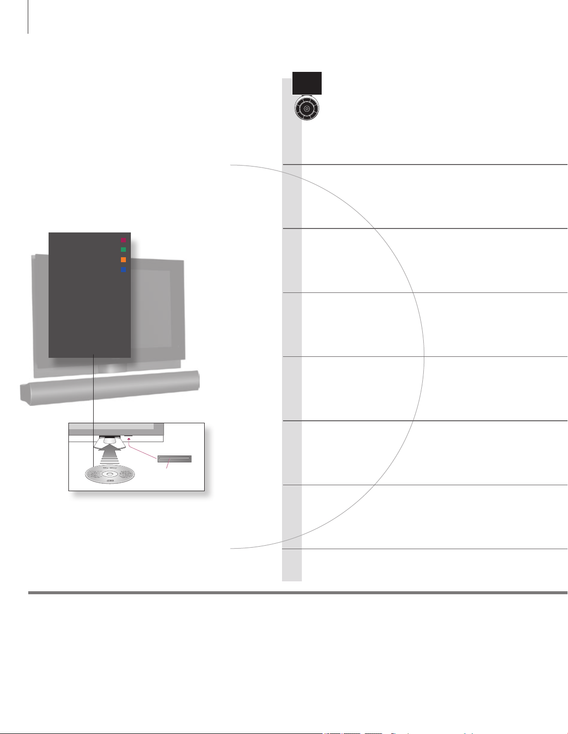
Use the Blu-ray player
If your TV is equipped with the optional Blu-ray player, you
can watch both Blu-ray discs and DVDs. With Blu-ray discs
the menu uses blue colours and with DVDs the menu uses
red colours.
Activate the source of the Blu-ray player to use these
functions
INF O 1
DIS C MEN U 2
POP UP/TI TLE 3
AUDI O 4
SUB TITLE S 5
REP EAT 6
BON US VIE W 7
DVD SETU P 8
Beo5 operation
Switch on the Blu-ray player
Select a function
Bring up different menus, e.g. INFO menu to move to specic title/
chapter or point in time. Change audio/subtitle language or angle.
Play a disc
Pause or stop playback
Pause or stop playback of a disc.
Not all Blu-ray discs support the resume function.
Press the load bar below the screen and
place the disc in the loader with the label
facing upwards. Hold the load bar to
begin playback automatically.
Important! Do not use disc adaptors.
Useful hints
‘ANGLE’ and ‘BONUS
VIEW ’ menus
‘SETUP’ menu
1
*Slow playback
Slow playback
Playback in slowmotion.*1
Change chapters or tracks
Step in chapters/tracks on a disc.
Switch off the Blu-ray player
ANGLE and BONUS VIEW menus are displayed if PLAYBACK STATUS is set to
EXTENDED in the SETUP menu and the information is available.
Use the main menu to make your own settings for playback.
Slow playback backwards is not possible.
NOTE! If you have a Beo4 without navigation
button, you must press the yellow button rst to
activate the Blu-ray player’s functions, e.g. resume
playback.
Page 15

Beo4 operation
15
Daily use
DVD
Press Press
… MENU 1–8
Select function
PLAY
Start playback
STOP
Once to pause, press again to stop.
Third to return to beginning of disc
Pause
playback
Slow playback Step in frames
PLAY
Resume playback
PLAYSTOP
Resume playback
DVD
LIST
or
Bring up menu
overlay
PLAY
Start playback
STOP
Once to pause, press again to stop.
Third to return to beginning of disc
STOP
Pause
playback
Press and bring up
SHIFT
or
Slow playback or step in
frames
Select
function
PLAY
Resume
playback
PLAY
Resume
playback
or
Step in chapters/tracks Cue during playback Resume playback
or
TV
Press
TV menu
Handling discs
On Beo4, press MENU t wice to bring up the TV’s main menu, when DVD is
selected as source.
If a loaded disc is not recognised, it is ejected and ‘LOAD’ is shown in the
display window. Check for disc faults such as ngerprints or scratches. The disc
may also have an incompatible format.
PLAY
or
Step or cue Resume
or
TV
Press
NOTE! If you are asked to press a coloured button,
press the specic button twice, if you have a Beo4
without navigation button.
PLAY
playback
Page 16

16
Change sound type and picture format
While you watch TV through the television tuner, you can switch between available
sound types and adjust the picture format.
Change sound type or language
Switch between available sound types and
languages.
Select picture format
The TV automatically adapts the picture to ll out
as much of the screen as possible when you select
a source, but you can select a format yourself.
Sound Sound
Bring up sound type*
Bring up Scene
display on Beo5
1
Press repeatedly to switch
between available sound
types
Select Picture
display*
FORMAT 1
4
For panoramic
view or 4:3
1
FORMAT 2
The picture is
adjusted ver tically
1–3
Select format*
2
Move picture up or down*
3
FORMAT 3
Wide Zoom Standard*
For a genuine
16:9 widescreen
picture
Useful hints
1
*Sound and picture
2
3*
Move picture up or down
*Optimise
4
*Variation
On Beo4 bring up SOUND for sound types and FORMAT for picture formats via the LIST menu. In order
to display SOUND and FORMAT on Beo4, you must rst add it to the Beo4 list of functions.
The picture format is optimised, if you press Optimise on Beo5. On Beo4, press the centre button.
The picture can only be moved up or down in Standard and Zoom.
In Standard, you can select variations of the format, if you press Variation on Beo5. On Beo4,
or .
press
Page 17

Use the Adaptive Sound Technology
To optimise the sound experience for your listening position, you can select a
customised listening preset and even rotate the sound to match the direction you
are facing.
17
Daily use
Select listening preset
When you watch television or listen to music, you
can select your own listening preset to optimise
the sound for your listening position. You can also
rotate the preset’s sound so that the sound is
experienced as coming from directly in front of
you. Adaptive Sound Technology must be enabled
and set up. See the Guide for further information.
Press
Preset … Rotate Rotate
Press
Select preset
and/or
Rotate sound
Remote control
Automatic selection of listening presets
To enjoy the advantages of this setup, several speakers and a Beo5 remote control are necessary. If you
have only a few speakers or a Beo4 remote control, this setup is not recommended and you should
choose the setup without Adaptive Sound Technology described in the Guide.
The sound automatically switches to the TV preset when you switch on the T V. You can set an AUDIO
PRESET in the SOUND ADJUSTMENT menu to make sound switch to a specic customised listening
preset automatically when you select an audio source.
Page 18

18
Page 19

Contents – Installation and setting up
20 Set up your television
21 Cleaning
22 Connection panels – BeoVision7-55
24 Connection panels – BeoVision7-40
26 First-time setup of your television
19
Installation and setting up
Page 20

20
Place the TV
When you place the TV, remember that the
built-in motor unit will turn and tilt the TV to a
preset position when you switch it on.
Ventilation
To ensure proper ventilation, allow enough space
above and below the screen. Do not cover the
fans.
Set up your television
Follow the guidelines for placement and connection described on this and the
following pages. Several stands and wall brackets are available from your retailer.
Due to the heavy weight of the T V, any moving or
lifting of the TV should be performed by qualied
personnel – using the proper equipment.
At overheating (ashing standby indicator and an
on-screen warning), switch the TV to standby, not
off, in order for the T V to cool down. You cannot
operate the T V during this time.
Motorised stand or wall bracket
Set the maximum angle the T V will turn. See the
Guide for further information.
Important
Tilt/turn
Front glass
If you have a motorised stand or a wall bracket,
leave enough space around the television to allow
it to turn and tilt freely.
When you mount the TV on a oor stand or wall bracket, you can tilt and turn the T V on some of the
stands. Only some stands can be tilted and turned with the remote control, other stands can only be
tilted manually.
If the front screen glass should crack or chip, or if it should be damaged in any way, it must be replaced
immediately, as it could otherwise cause injur y. You can order replacement front screen glass from your
Bang& Olufsen retailer.
Page 21

Overview – BeoVision7-55
Locate the connection panels and other important
items.
1 Cover for sockets for temporary connection,
such as camera and headphones sockets. Push
in to open, push again to close.
2 Not in use.
3 Mounting bracket for stand or wall bracket.
1
4 Covers for the connection panel. Here you also
nd the mains supply connection. Pull out at the
2
bottom to remove.
3
4
21
Overview – BeoVision7-40
Locate the connection panels and other important
items.
Cleaning
Maintenance
Screen
Cabinet and controls
Never alcohol
Regular maintenance, such as cleaning, is the responsibility of the user.
Use a mild window cleaning uid and lightly clean the screen without leaving streaks or traces. Some micro-bre cloths
may harm the optical coating due to their strong abrasive effect.
Wipe dust off the surfaces using a dry, soft cloth. To remove stains or dirt, use a soft, damp cloth and a solution of water
and mild detergent, such as washing-up liquid.
Never use alcohol or other solvents to clean any parts of the TV.
1 Cover for sockets for temporary connection,
such as camera and headphones sockets. Push
in to open, push again to close.
2 Mounting bracket for stand or wall bracket.
1
3 Covers for the connection panel. Here you also
nd the mains supply connection. Pull out at the
2
bottom to remove.
3
Installation and setting up
Page 22

22
Connection panels – BeoVision7-55
Any equipment you connect to the main connection panel must be registered in
the CONNECTIONS menu. Equipment connected to the side connection panel can
be registered in the CONNECTIONS menu.
Ethernet*
1
For connection to the Internet.
ATSC
Aerial input socket for the ATSC tuner.
VGA IN
Socket for connection of a High Denition video
source or a PC.
LINK TV OUT
Aerial output for distribution of video signals to
other rooms.
CINEMA CONTROL
For a Home Automation system.
PROJECTOR OUT (DVI- D OUT)
Connect a projector.
HDMI IN (A–D)
For High Denition Multimedia Interface video
source or PC. An HDMI socket may be occupied
by built-in video equipment. The sources can be
registered to any of the AV socket groups. To
expand the number of HDMI sockets, connect an
HDMI Expander to the HDMIC socket.
~ – Mains supply
Connection to the mains supply.
AV1
Socket group for AV connection of a primary
recorder or set-top box. You can also connect other
types of extra video equipment.
AV2
Socket group for AV connection of additional video
equip ment.
SPDIF PUC
STAND
VIDEO
IN
L-IN
R-IN
LINK TV
OUT
HDMI INDVI-D OUT
TTL RS232 P UC 1+2 IR-IN
CONTROL
VIDEO
Y
OUT
L-OUT
Pb
R-OUT
Pr
CINEMA CONTROL
MASTER LINK
SPDIF
SPDIF
PUC
ATSC
PROJECTOR OUT B C D
VIDEO
IN
VIDEO
VIDEO
IN
L-IN
L-OUT SPDIF
R-IN
R-OUT PUC
AV 1 AV 3AV 2
VGA IN
A
R INL IN
AV 5
PUC
OUT
AV3
Socket group for AV connection of additional
video equip ment.
The TV keeps a signal path open between a
recorder connected to the AV1 socket and a
recordable source connected to the AV3 socket.
This allows you to set the source on AV3 to switch
on automatically, as well as set a recorder on AV1
for timed recording of the source on AV3, provided
your connected equipment supports these functions.
AV4
Occupied by the optional Blu-ray player.
AV5
Socket group for AV connection of additional
video equip ment.
CENTRE
1
1 (SUB)
2
POWER
3
LINK
VIDEO
IN
L-IN
R-IN
Y
Pb
Pr
Analogue
4
5
6
AV6 (CAMERA)
Socket group for AV connection of additional
video equip ment. You can also connect
headphones, a camera or a camcorder. This socket
group is placed on the side connection panel. See
the illustration on page23.
PUC (AV1 – AV3, AV5 – AV6)
For IR control signals to external equipment
connected to an AV socket.
L-IN, R-IN (AV1 – AV3, AV5 – AV6)
Right and left line input. AV6 is for audio
connection of, e.g., a camera or camcorder.
L-R-OUT (AV1 – AV2)
Right and left line output.
Useful hints
Mains cord and plug The supplied plug and mains cord are specially designed for the product. Do
not change the plug and if the mains cord is damaged, you must buy a new
one from your Bang& Olufsen retailer. Connect the ~socket on the main
connection panel of your T V to the wall outlet. The IR-receiver lights up in red
and the TV is in standby mode and ready to be used.
1
*NOTE! Only connect to a local area network
(LAN) that does not exit your at, house or
building.
Page 23

Some sockets on the illustration of the main connection panel may be occupied by internal connections. Do not disconnect
the cables from these sockets!
23
VIDEO IN (AV1 – AV3, AV5 – AV6)
For video signal. On AV6 you can connect a
camera or a camcorder.
VIDEO OUT (AV1 – AV2)
Connect a video recorder.
Y – Pb – Pr (AV2 – AV3)
For video signals from an external source, e.g.
HDTV source. You can use the socket in
conjunction with an AV socket or a digital audio
socket.
SPDIF (AV1 – AV3, AV5 – AV6)
Digital audio input socket, e.g. DVD player.
TTL /RS232
Only for use in Hotel setups.
PUC 1+2
For an external IR-transmitter used with Home
cinema setups or an HDMI Expander.
IR IN
For an extra IR-receiver when the TV is set up with
a projector.
STAND
For connection of a motorised stand.
MASTER LINK
For a compatible Bang& Olufsen audio or video
system. The socket is also used for BeoLink
distribution of sound and picture throughout the
house.
CENTRE 1
For connection of a centre speaker, e.g. BeoLab 7.
For further information, see the speaker’s own
guide.
POWER LINK 1–6
For connection of external speakers in a surround
sound setup. See the Guide for further
information.
1 (SUB)
For connection of up to two Bang & Olufsen
subwoofers. A cable splitter for such connections
is available from your Bang & Olufsen retailer.
S-VIDEO (AV6)
For the connection of, e.g., a game console.
S-VIDEO
VIDEO IN
SPDIF
L IN
R IN
PUC
PHONES
The AV6 socket group is placed on the side
connection panel.
PHONES
For connection of stereo headphones.
> To mute speakers turn the volume wheel quickly
counter-clockwise. (Beo4: Press in the middle of
button).
the
> Turn the volume wheel either way to adjust
volume in headphones. (Beo4: Press or ).
> To restore sound in speakers, turn the volume
wheel quickly counter-clockwise. (Beo4: Press
the middle of the button).
NOTE! Prolonged listening at high volume levels
can cause hearing damage!
Installation and setting up
Analogue (ANT.)
Aerial input sockets for an external aerial/cable T V
network.
NOTE! Video recorders can only be connected to
the AV1 and AV2 socket groups, as these are the
only sockets groups for video output. Connect the
primary recorder to AV1 and the secondary
recorder to AV2.
Page 24

24
PROJECTOR OUT (DVI- D OUT)
Connect a projector.
HDMI IN (A–D)
For High Denition Multimedia Interface video
source or PC. An HDMI socket may be occupied
by built-in video equipment. The sources can be
registered to any of the AV socket groups. To
expand the number of HDMI sockets, connect an
HDMI Expander to the HDMIC socket.
AV1
Socket group for AV connection of a primary
recorder or set-top box. You can also connect other
types of extra video equipment.
AV2
Socket group for AV connection of additional video
equip ment.
AV3
Socket group for AV connection of additional
video equip ment.
The TV keeps a signal path open between a
recorder connected to the AV1 socket and a
recordable source connected to the AV3 socket.
This allows you to set the source on AV3 to switch
on automatically, as well as set a recorder on AV1
for timed recording of the source on AV3, provided
your connected equipment supports these functions.
AV4
Occupied by the optional Blu-ray player.
AV5
Socket group for AV connection of additional
video equip ment.
AV6 (CAMERA)
Socket group for AV connection of additional
video equip ment. You can also connect
headphones, a camera or a camcorder. This socket
group is placed on the side connection panel. See
the illustration on page25.
Connection panels – BeoVision7-40
Any equipment you connect to the main connection panel must be registered in
the CONNECTIONS menu. Equipment connected to the side connection panel can
be registered in the CONNECTIONS menu.
ATSC
1
ANT
Analogue
2
LINK TV
OUT
POWER
LINK
CENTRE
1 (SUB)
1
2
3
4
5
6
APROJECTOR OUT B C D
HDMI INDVI-D OUT
VIDEO
VIDEO
L-IN
R-IN
IN
IN
R INL IN
SPDIF PUC
AV 5
STAND
VIDEO
OUT
L-OUT SPDIF
R-OUT PUC
AV 1 AV 3AV 2
VIDEO
PUC
VIDEO
IN
OUT
L-IN
L-OUT
R-IN
R-OUT
TTL RS232 P UC 1+2 IR-IN
Y
Pb
Pr
PUC (AV1 – AV3, AV5 – AV6)
For IR control signals to external equipment
connected to an AV socket.
L-IN, R-IN (AV1 – AV3, AV5 – AV6)
Right and left line input. AV6 is for audio
connection of, e.g., a camera or camcorder.
L-R OUT (AV1 – AV2)
Right and left line output.
VIDEO IN (AV1 – AV3, AV5 – AV6)
For video signal. On AV6 you can connect a
camera or a camcorder.
VIDEO OUT (AV1 – AV2)
Connect a video recorder.
CONTROL
MASTER LINK
SPDIF
SPDIF
PUC
CINEMA CONTROL
VGA IN
VIDEO
Y
IN
L-IN
Pb
R-IN
Pr
Y – Pb – Pr (AV2 – AV3)
For video signals from an external source, e.g.
HDTV source. You can use the socket in
conjunction with an AV socket or a digital audio
socket.
SPDIF (AV1 – AV3, AV5 – AV6)
Digital audio input socket, e.g. DVD player.
TTL /RS232
Only for use in Hotel setups.
PUC 1+2
For an external IR-transmitter used with Home
cinema setups or an HDMI Expander.
Useful hints
Mains cord and plug The supplied plug and mains cord are specially designed for the product. Do not change the plug and if
the mains cord is damaged, you must buy a new one from your Bang& Olufsen retailer. Connect the
~socket on the main connection panel of your T V to the wall outlet. The IR-receiver lights up in red and
the TV is in standby mode and ready to be used.
Page 25

Some sockets on the illustration of the main connection panel may be occupied by internal connections. Do not disconnect
the cables from these sockets!
25
IR IN
For an extra IR-receiver when the TV is set up with
a projector.
STAND
For connection of a motorised stand.
MASTER LINK
For a compatible Bang& Olufsen audio or video
system. The socket is also used for BeoLink
distribution of sound and picture throughout the
house.
CINEMA CONTROL
For a Home Automation system.
Ethernet*
1
For connection to the Internet.
VGA IN
Socket for connection of a High Denition video
source or a PC.
ANT1 (Analogue)
Aerial input sockets for an external aerial/cable T V
network.
ANT2 (ATSC )
Aerial input socket for an external aerial/cable TV
network.
LINK TV OUT
Aerial output for distribution of video signals to
other rooms.
1 (SUB)
For connection of up to two Bang & Olufsen
subwoofers. A cable splitter for such connections
is available from your Bang & Olufsen retailer.
~ – Mains supply
Connection to the mains supply.
S-VIDEO (AV6)
For the connection of, e.g., a game console.
SPDIF
R IN
L IN
PHONES
PUC
VIDEO IN
S-VIDEO
The AV6 socket group is placed on the side
connection panel.
PHONES
For connection of stereo headphones.
> To mute speakers turn the volume wheel quickly
counter-clockwise. (Beo4: Press in the middle of
button).
the
> Turn the volume wheel either way to adjust
volume in headphones. (Beo4: Press or ).
> To restore sound in speakers, turn the volume
wheel quickly counter-clockwise. (Beo4: Press
the middle of the button).
NOTE! Prolonged listening at high volume levels
can cause hearing damage!
Installation and setting up
CENTRE 1
For connection of a centre speaker, e.g. BeoLab 7.
For further information, see the speaker’s own
guide.
POWER LINK 1–6
For connection of external speakers in a surround
sound setup. See the Guide for further
information.
1
*Network Only connect to a local area network (LAN) that does not exit your at, house
or building.
NOTE! Video recorders can only be connected to
the AV1 and AV2 socket groups, as these are the
only sockets groups for video output. Connect the
primary recorder to AV1 and the secondary
recorder to AV2.
Page 26

26
First-time setup of your television
This rst-time setup procedure is activated when the TV is connected to the mains
and switched on for the rst time. If you want to change your setup at a later date,
you can access the same menus and update your settings.
Switch on the TV
It takes the T V approx. 20 seconds to start up and
become ready for use.
Select settings
You are led through the following settings only
when you switch on the TV for the rst time.*1
However, the sequence of menus depend on the
connections and settings you make.
Calibrate the speakers
Set up the speakers to optimise sound from your
listening position. To enjoy Adaptive Sound
Technology several speakers and a Beo5 remote
control are necessary.
TV
Switch on
or
Select setting Accept and go to next menu item
TUNER SETUP
REMOTE CONTROL
CONNECTIONS
AST ON/OFF
AST ON:
SPEAKER SETUP
TV LISTENING PRESET
CINEMA LISTENING PRESET
Disable or enable internal TV tuner or ATSC
Disable or enable the navigation button on your remote control*
Register connected equipment
Disable or enable Adaptive Sound Technology
AST OFF:
SPEAKER TYPES
SPEAKER ROLES
SPEAKER DISTANCE
SPEAKER LEVEL
2
First-time setup of loudspeakers
applies only to speakers for TV viewing.
See the Guide for further information.
Information
Tuner setup
Connections
SOUND ADJUSTMENT
SOUND SETUP
If you select CABLE BOX, follow the on-screen information to specify
which cable box you have connected to the TV. If you select ANTENNA or
CABLE, a scanning process begins when you store the setting. See the
Guide for further information.
Select the type of equipment connected to each socket, the sockets used,
the product name, and the source name.
SOUND ADJUSTMENT
Adjust volume, bass, treble and
loudness and preset two default
speaker combinations.
Make settings for each listening preset.
See the Guide for further information.
1
*NOTE! When you have selected the preferred
settings in a menu, you may have to press the
green button to continue to the next menu in the
rst-time setup procedure. Follow on-screen
instructions.
Page 27

27
Calibrate the stand
Set the maximum angle the T V will turn – left and
right. The motorised movement of the TV will not
work until the calibration process has been
completed.
STAND ADJUSTMENT
STAND POSITIONS
At SET LEFTMOST
POSITION turn left to the
point you wish to restrict
the movement to
At SET TOP POSITION tilt
up to the point you wish
to restrict the movement
3
to
*
At SET RIGHTMOST
POSITION turn right to the
point you wish to restrict the
movement to
At SET BOTTOM POSITION tilt
down to the point you wish to
restrict the movement to
3
*
Accept*
Set preferred preset position for the TV to turn to, when it is switched on and
off. You need to calibrate the stand before you can use the motorised
movement of the stand.
1
Installation and setting up
2
*Navigation button
3
*Tilt
This Getting Started and the Guide describe operation with the REMOTE
CONTROL menu set to NAVIGATION BUTTON and the remote control
set to MODE1. Do not change MODE during rst-time setup, as this will
interrupt the sequence.
If you have a Beo4 without navigation button or if your Beo4 is not set to the
correct mode, you cannot enable the navigation button. See the Beo4 guide
or contact your Bang& Olufsen retailer for further information.
If you have a Beo4 without navigation button, or if the navigation button on
your remote control is disabled, use the green button to tilt the television up
and the red button to tilt it down.
NOTE! For further information about remote
controls and rst-time setup, see the Guide.
Page 28

28
Waste Electrical and Electronic Equipment
(WEEE) – Environmental protection
Electrical and electronic equipment, parts and
batteries marked with this symbol must not be
disposed of with normal household wastage; all
electrical and electronic equipment, parts and
batteries must be collected and disposed of
separately.
When disposing of electrical and electronic
equipment and batteries by use of the collection
systems available in your country, you protect the
environment, human health and contribute to the
prudent and rational use of natural resources.
All Bang & Olufsen products comply with applicable environmental legislation throughout the world.
The DVD Video logo is a registered
trademark.
“Blu-ray Disc” and the Blu-ray Disc
logo are registered trademarks.
“BONUSVIEW” is a registered
trademark of Blu-ray Disc
Association.
Collecting electrical and electronic equipment,
batteries and waste prevents the potential
contamination of nature with the hazardous
substances which may be present in electrical and
electronic products and equipment.
Your Bang& Olufsen retailer will advise you of the
correct way of disposal in your country.
If a product is too small to be marked with the
symbol, it will appear in the User Guide, on the
Guarantee certicate, or on the packaging.
Manufactured under license from
Dolby Laboratories. Dolby, Pro Logic,
and the double-D symbol are
registered trademarks of
Dolby Laboratories.
Confidential unpublished works.
Copyright 1992–2003 Dolby
Laboratories.
All rights reserved.
Java Technology – a registered
trademark of Sun Microsystems.
Manufactured under license
under U.S. Patent # ’s: 5,451,942;
5,956,674; 5,974,380; 5,978,762;
6,487,535; 7,003,467; 7,212,872
& other U.S. and worldwide
patents issued & pending.
DTS, DTS Digital Surround, ES,
and Neo:6 are registered
trademarks and the DTS logos,
and Symbol are trademarks of
DTS, Inc.
© 1996–2008 DTS, Inc.
All Rights Reserved.
U.S. Patent’s 6,836,549;
6,381,747; 7,050,698; 6,516,132;
and 5,583,936
Page 29

29
CLASS 1
LASER PRODUCT
The label on the compact disc player serves as a
warning that the apparatus contains a laser system
and is classied as a class 1 laser product. In case
any difculties arise with the compact disc player,
please contact a Bang & Olufsen retailer. The
apparatus must be opened by qualied ser vice
personnel only.
CAUTION: The use of any controls, adjustments
or procedures other than those specied herein
may result in hazardous radiation exposure. The
use of optical instruments with this product will
increase eye hazard. As the laser beam used in this
CD/DVD Player is harmful to eyes, do not attempt to
disassemble the cabinet. Refer servicing to qualied
personnel only. Laser radiation when open. Do not
stare into beam. This label is located on the rear
enclosure.
This product incorporates copyright protection
technology that is protected by U.S. patents and
other intellectual property rights. Use of this
copyright protection technology must be
authorized by Macrovision, and is intended for
home and other limited viewing uses only unless
otherwise authorized by Macrovision. Reverse
engineering or disassembly is prohibited.
For the US -market only!
NOTE: This equipment has been tested and found
to comply with the limits for a class B digital
device, pursuant to part 15 of the FCC Rules.
These limits are designed to provide reasonable
protection against harm ful interference in a
residential installation.
This equipment generates, uses and can radiate
radio frequency energy and, if not installed and
used in accordance with the instructions, may
cause harmful interference to radio
communications. However, there is no guarantee
that interference will not occur in a particular
installation. If this equipment does cause harmful
interference to radio or television reception, which
can be determined by turning the equip ment off
and on, the user is encouraged to try to correct
the interference by one or more of the following
measures:
– Reorient or relocate the receiving antenna.
– Increase the separation between the equipment
and receiver.
– Connect the equipment into an outlet on a
circuit different from that to which the receiver
is connected.
– Consult the retailer or an experienced radio/TV
technician for help.
For the Canadian market only!
This class B digital apparatus meets all require-
ments of the Canadian Interference-Causing
Equipment Regulations.
HDMI, the HDMI Logo and High-Denition
Multimedia Interface are trademarks or registered
trademarks of HDMI Licensing LLC.
Page 30

Page 31

Page 32

 Loading...