


VS1GV21-4B
Baldor VS1GV21-4B, VS1GV23-1B, VS1GV22-5B, VS1GV21-5B, VS1GV23-5B Installation & Operating Manual
...
VS1GV
AC Closed Vector Control
10/11 Installation & Operating Manual MN765

Any trademarks used in this manual are the property of their respective owners.
Important:
Be sure to check www.baldor.com for the latest software, rmware and drivers for your VS1GV product. Also you can
download the latest version of this manual in Adobe Acrobat PDF format.

Table of Contents
Chapter 1
Introduction
1.1 Getting Assistance from Baldor ..................................................... 1-1
1.2 Safety Notices ................................................................... 1-1
1.3 Quick Start ...................................................................... 1-3
Chapter 2
General Information and Ratings
2.1 Limited Warranty ................................................................. 2-1
2.2 Standards ....................................................................... 2-1
2.2.1 Design and Test Standards .................................................... 2-1
2.2.2 Environmental Test Standards .................................................. 2-1
2.2.3 Marks ..................................................................... 2-1
Chapter 3
Installing the Drive
3.1 Receiving & Inspection ............................................................ 3-1
3.2 General Requirements for the Installation Site .......................................... 3-1
3.2.1 Location Instructions ........................................................ 3-1
3.2.2 Minimum Mounting Clearances ................................................ 3-1
3.3 Mounting the Drive ................................................................ 3-1
3.3.1 Protecting the Drive from Debris ................................................ 3-1
3.3.2 Watts Loss Data ............................................................. 3-1
3.4 Cover Removal. . . . . . . . . . . . . . . . . . . . . . . . . . . . . . . . . . . . . . . . . . . . . . . . . . . . . . . . . . . . . . . . . . . 3-2
Chapter 4
Power Wiring
4.1 Grounding the Drive ............................................................... 4-1
4.1.1 Ungrounded Distribution System ................................................ 4-1
4.1.2 Input Power Conditioning ..................................................... 4-1
4.2 Line Impedence .................................................................. 4-1
4.2.1 Line Reactors ............................................................... 4-2
4.2.2 Load Reactors .............................................................. 4-2
4.3 Line Disconnect .................................................................. 4-2
4.4 Protective Devices ............................................................... 4-2
4.5 Reduced Input Voltage Considerations ................................................ 4-3
4.6 Electrical Installation .............................................................. 4-3
4.7 Optional Filter/Reactor ............................................................. 4-3
4.8 Incoming Power and Motor Connections .............................................. 4-6
4.9 Operating a 3-Phase Control on Single Phase Input Power ................................ 4-7
4.9.1 Single Phase Power Derating .................................................. 4-7
4.10 M-Contactor ................................................................... 4-11
4.11 Long Motor Leads ............................................................... 4-11
4.12 Optional Dynamic Brake Hardware .................................................. 4-12
4.13 Encoder Installation .............................................................. 4-13
4.14 Home (Orient) Switch Input ........................................................ 4-14
iMN765

Chapter 5
Control Wiring
5.1 Control Board Connections ......................................................... 5-1
5.2 Analog Inputs .................................................................... 5-3
5.2.1 Analog Input 1 .............................................................. 5-3
5.2.2 Analog Input 2 .............................................................. 5-3
5.3 Analog Outputs .................................................................. 5-4
5.4 Opto-Isolated Inputs .............................................................. 5-4
5.5 Operating Modes ................................................................ 5-5
5.5.1 Keypad .................................................................... 5-5
5.5.2 Standard Run 2-Wire ......................................................... 5-6
5.5.3 Standard Run 3-Wire ......................................................... 5-7
5.5.4 15 Preset Speeds ............................................................ 5-8
5.5.5 Fan Pump 2-Wire ............................................................ 5-9
5.5.6 Fan Pump 3-Wire ............................................................ 5-10
5.5.7 Process Control ............................................................. 5-11
5.5.8 3 Speed Analog 2-Wire ....................................................... 5-12
5.5.9 3 Speed Analog 3-Wire ....................................................... 5-13
5.5.10 E-POT 2-Wire .............................................................. 5-14
5.5.11 E-POT 3-Wire .............................................................. 5-15
5.5.12 Network .................................................................. 5-16
5.5.13 Prole Run ................................................................ 5-17
5.5.14 15 Preset Position .......................................................... 5-18
5.5.15 Bipolar ................................................................... 5-21
5.5.16 Pulse Follower ............................................................. 5-23
5.5.17 PLC ..................................................................... 5-23
5.6 Digital Outputs ................................................................... 5-23
5.7 Relay Outputs ................................................................... 5-24
5.8 USB Port ....................................................................... 5-24
5.9 Communication Expansion Boards .................................................. 5-25
5.9.1 RS485 Modbus ............................................................. 5-25
5.10 Opto-Isolated Inputs ............................................................. 5-26
5.11 Opto-Isolated Outputs ............................................................ 5-26
5.12 Pre-Operation Checklist .......................................................... 5-27
5.13 Powerup Procedure ............................................................. 5-27
5.14 Mint WorkBench. . . . . . . . . . . . . . . . . . . . . . . . . . . . . . . . . . . . . . . . . . . . . . . . . . . . . . . . . . . . . . . . . 5-28
5.14.1 Install USB Driver ........................................................... 5-28
5.14.2 Install Mint WorkBench ...................................................... 5-29
5.14.3 Update Firmware ........................................................... 5-31
ii MN765

Chapter 6
Using the Keypad
6.1 Keypad Components .............................................................. 6-1
6.1.1 Display Description .......................................................... 6-1
6.1.2 Display Features ............................................................ 6-2
6.2 Status Mode ..................................................................... 6-3
6.3 Menu Display .................................................................... 6-4
6.4 Basic Params ................................................................... 6-4
6.5 Save Parameter Values ............................................................ 6-7
6.6 Restore Parameter Values .......................................................... 6-8
6.7 Advanced Prog .................................................................. 6-9
6.7.1 Modied Parameters ......................................................... 6-10
6.7.2 Linear List .................................................................. 6-10
6.8 Event Log ....................................................................... 6-11
6.9 Diagnostics ..................................................................... 6-12
6.10 Display Options ................................................................. 6-14
6.11 Operating the Control from the Keypad ............................................... 6-15
6.11.1 Accessing the Keypad JOG Command .......................................... 6-15
6.11.2 Speed Adjustment using Local Speed Reference .................................. 6-15
Chapter 7
Parameter Descriptions
7.1 Level 1 Parameters (Advanced Prog, Level 1 Blocks) ..................................... 7-1
7.2 Level 2 Parameters (Advanced Prog, Level 2 Blocks) .................................... 7-16
7.3 Level 3 Parameters (Advanced Prog, Level 3 Blocks) ..................................... 7-31
Chapter 8
Customizing Your Application
8.1 Customizing Your Application ....................................................... 8-1
Chapter 9
Troubleshooting
9.1 Event Log ....................................................................... 9-1
9.2 Diagnostic Information ............................................................. 9-6
9.3 Fault Messages .................................................................. 9-8
9.4 Electrical Noise Considerations ..................................................... 9-13
Chapter 10
PLC Mode Description
10.1 Overview ...................................................................... 10-1
10.2 Conguring Parameters ........................................................... 10-1
10.3 Comparator Function ............................................................. 10-1
10.4 Timers ........................................................................ 10-2
10.5 PLC Mode as Standard Run 2-Wire Mode ............................................ 10-8
10.6 PLC Mode as 15 Preset Speed Mode ................................................ 10-9
10.7 PLC Mode as Process PID Mode ................................................... 10-10
10.8 PLC Mode as a Modied Process PID Mode .......................................... 10-11
iiiMN765

Chapter 11
Composite Reference Description
11.1 Overview ...................................................................... 11-1
11.2 Composite Reference Examples .................................................... 11-2
Chapter 12
Monitor and RTC Description
12.1 Monitor Parameters (P0001 to P0202) ................................................ 12-1
12.2 Real Time Clock (RTC) Overview .................................................... 12-6
Appendix A
Technical Specifications
A.1 VS1GV Specications ............................................................. A-1
A.2 Specications for Power Terminal Block Wiring ......................................... A-4
A.3 Identifying the Drive by Model Number ................................................ A-5
A.4 Storage Guidelines ............................................................... A-6
A.5 VS1GV Drive Ratings, Model Numbers and Frame Sizes .................................. A-6
A.6 VS1GV Terminal Wire Gauge Specications ............................................ A-10
A.7 Drive Dimensions and Weights ...................................................... A-12
Appendix B
Parameter Tables
B.1 Level 1 Parameters (Advanced Prog, Level 1 Blocks) ..................................... B-1
B.2 Level 2 Parameters (Advanced Prog, Level 2 Blocks) ..................................... B-9
B.3 Level 3 Parameters (Advanced Prog, Level 3 Blocks) ..................................... B-14
Appendix C
CE Guidelines
C.1 Outline ........................................................................ C-1
C.2 EMC - Conformity and CE Marking ................................................... C-1
C.3 EMC Installation Options ........................................................... C-2
C.4 Grounding the Wall Mounting (Class A) ............................................... C-2
C.5 Grounding the Enclosure Mounting (Class B) ........................................... C-2
C.6 Use of CE Compliant Components ................................................... C-2
C.7 EMC Wiring Technique ............................................................ C-3
C.8 EMC Installation Instructions. . . . . . . . . . . . . . . . . . . . . . . . . . . . . . . . . . . . . . . . . . . . . . . . . . . . . . . . C-4
Appendix D
Options and Kits
D.1 Dynamic Braking (DB) Hardware ..................................................... D-1
D.2 Expansion Boards ................................................................ D-2
D.3 Keypad Extension Cables .......................................................... D-3
D.4 Optional Remote Keypad Installation ................................................. D-4
Appendix E
Remote Keypad Mounting Template
Remote Keypad Mounting Template ..................................................... E-1
iv MN765

Chapter 1
Introduction
The information in this manual supports rmware versions up through 1.23.
This manual is intended for qualied electrical personnel familiar with installing, programming, and maintaining AC Drives.
This manual contains information on:
• Installing and wiring the VS1GV drive
• Programming the drive
• Troubleshooting the drive
1.1 Getting Assistance from Baldor
For technical assistance, contact your Baldor District Ofce. Before calling, please review the troubleshooting section of this
manual. You will be asked for the drive model number or catalog number that is located on the nameplate along with the
drive serial number.
1.2 Safety Notices
This equipment contains voltages that may be as high as 1000 volts! Electrical shock can cause serious or fatal injury. Only
qualied personnel should attempt the start-up procedure or troubleshoot this equipment.
This equipment may be connected to other machines that have rotating parts or parts that are driven by this equipment.
Improper use can cause serious or fatal injury. Only qualied personnel should attempt the start-up procedure or
troubleshoot this equipment.
CLASSIFICATIONS OF CAUTIONARY STATEMENTS:
WARNING: Indicates a potentially hazardous situation which, if not avoided, could result in injury or death.
CAUTION: Indicates a potentially hazardous situation which, if not avoided, could result in damage to
property.
PRECAUTIONS:
WARNING: Do not touch any circuit board, power device or electrical connection before you first ensure
that power has been disconnected and there is no high voltage present from this equipment or
other equipment to which it is connected. Electrical shock can cause serious or fatal injury. Only
qualified personnel should attempt the start-up procedure or troubleshoot this equipment.
WARNING: Be sure that you are completely familiar with the safe operation of this equipment. This equipment
may be connected to other machines that have rotating parts or parts that are controlled by this
equipment. Improper use can cause serious or fatal injury. Only qualified personnel should
attempt the start-up procedure or troubleshoot this equipment.
WARNING: Do not use motor overload relays with an automatic reset feature. These are dangerous since the
process may injure someone if a sudden or unexpected automatic restart occurs. If manual reset
relays are not available, disable the automatic restart feature using external control wiring.
WARNING: This unit has an automatic restart feature that will start the motor whenever input power is
applied and a RUN (FWD or REV) command is issued. If an automatic restart of the motor could
cause injury to personnel, the automatic restart feature should be disabled.
WARNING: Be sure the system is properly grounded before applying power. Do not apply AC power before
you ensure that all grounding instructions have been followed. Electrical shock can cause serious
or fatal injury.
WARNING: Do not remove cover or open door for at least five (5) minutes after AC power is disconnected to
allow capacitors to discharge. Dangerous voltages are present inside the equipment. Electrical
shock can cause serious or fatal injury.
WARNING: Improper operation of control may cause violent motion of the motor shaft and driven equipment.
Be certain that unexpected motor shaft movement will not cause injury to personnel or damage
to equipment. Certain failure modes of the control can produce peak torque of several times the
rated motor torque.
WARNING: Motor circuit may have high voltage present whenever AC power is applied, even when motor is
not rotating. Electrical shock can cause serious or fatal injury.
WARNING: Dynamic brake resistors may generate enough heat to ignite combustible materials. Keep all
combustible materials and flammable vapors away from brake resistors.
Introduction 1-1MN765

WARNING: The motor shaft will rotate during the autotune procedure. Be certain that unexpected motor shaft
movement will not cause injury to personnel or damage to equipment.
WARNING: MEDICAL DEVICE/PACEMAKER DANGER - Magnetic and electromagnetic fields in the vicinity
of current carrying conductors and industrial motors can result in a serious health hazard to
persons with cardiac pacemakers, internal cardiac defibrillators, neurostimulators, metal
implants, cochlear implants, hearing aids, and other medical devices. To avoid risk, stay away
from the area surrounding a motor and its current carrying conductors.
CAUTION: Disconnect motor leads (T1, T2 and T3) from control before you perform a dielectric withstand
(insulation) test on the motor. Failure to disconnect motor from the control will result in extensive
damage to the control. The control is tested at the factory for high voltage/leakage resistance as
part of the Underwriters Laboratory requirements.
CAUTION: Suitable for use on a circuit capable of delivering not more than the RMS symmetrical short circuit
amperes listed here at rated voltage.
Horsepower RMS Symmetrical Amperes
1-50 5,000
51-200 10,000
201-400 18,000
401-600 30,000
601-900 42,000
CAUTION: Do not connect AC power to the Motor terminals T1, T2 and T3. Connecting AC power to these
terminals may result in damage to the control.
CAUTION: Baldor does not recommend using “Grounded Leg Delta” transformer supplies that may create
ground loops. Instead, we recommend using a four wire Wye.
CAUTION: Do not supply any power to the External Trip (motor thermostat) leads at TH1 and TH2. Power on
these leads can damage the control. Use a dry contact type that requires no external power to
operate.
CAUTION: If a customer installed Dynamic Brake (DB) hardware mounting is in any position other than
vertical, the DB hardware must be derated by 35% of its rated capacity.
CAUTION: Before external Dynamic Brake Hardware is added, the internal resistor must be disconnected
(frames AA, B, C and D only). Remove the resistor from the B+/R1 and R2 terminals and insulate
the leads to avoid accidental connection to drive circuity. The external resistor can be connected
across these terminals. Failure to remove the internal resistor will decrease the total resistance
(parallel connection) and cause damage.
CAUTION: Do not set Level 2, Drive Configure, Power Input parameter to Common Bus if AC power
is connected to L1, L2 or L3. Common Bus requires numerous changes. Contact Baldor for
information.
CAUTION: Only Baldor cables should be used to connect the keypad and control. These are special twisted
pair cables to protect the control and keypad. Damage associated with other cable types are not
covered by the Baldor warranty.
CAUTION: If an M-Contactor is installed, the control must be disabled for at least 200msec before the
M-Contactor is opened. If the M-Contactor is opened while the control is supplying voltage and
current to the motor, the control may be damaged. Before the control is enabled, the M-Contactor
must be closed for at least 200msec.
CAUTION: Use of power correction capacitors on the output of the drive can result in erratic operation
of the motor, nuisance tripping, and/or permanent damage to the drive. Remove power
correction capacitors before proceeding. Failure to observe this precaution could result in
damage to, or destruction of, the equipment.
CAUTION: Do not connect any shields to the encoder case or motor frame. The encoder +5/12VDC supply
at pins 8 and 9 of the encoder board is referenced to circuit board common. Do not connect any
shields to ground or another power supply or damage to the control may result.
CAUTION: Motor thermostat leads must be routed in a separate conduit than the motor power leads. Failure
to isolate these connections may cause nuisance trips, misoperation or component failure.
1-2 Introduction MN765

1.3 Quick Start
Quick Start Guide MS765 is also available separately from www.baldor.com.
If you are an experienced user of Baldor controls, you are probably already familiar with the keypad programming and
keypad operation methods. If so, this quick start guide has been prepared for you. This procedure will help get your system
up and running in the keypad mode quickly and allows motor and control operation to be veried. This procedure assumes
that the Control, Motor and Dynamic Brake hardware are correctly installed (see Chapters 3, 4, and 5 for procedures)
and that you have an understanding of the keypad programming and operation procedures. Figure 1-1 shows minimum
connection requirements. It is not necessary to wire the terminal strip to operate in Keypad mode (Chapter 5 describes
terminal strip wiring procedures).
The quick start procedure is as follows:
1. Read the Safety Notice and Precautions in this Chapter.
2. Mount the control. Refer to Chapters 3, 4, and 5 “Physical Location” procedure.
3. Connect AC power ensuring source voltage matches drive voltage (Figure 1-1). See wire and fuse size guidelines in
Chapter 4. Torque connections per Table A-2.
4. Connect the motor ensuring motor is wired for same voltage as drive (Figure 1-1). Torque connections per Table A-2. Do
not couple the motor shaft to the load until auto tune is complete.
5. Install Dynamic brake hardware, if required. Refer to Chapter 4 “Optional Dynamic Brake Hardware.”
6. Connect motor thermostat leads to TH1 and TH2 after removing factory supplied jumper. Be sure to route these leads in
a separate conduit from the motor power leads.
CAUTION: After completing the installation but before you apply power, be sure to check the following
electrical items:
1. Verify AC line voltage at source matches control rating.
2. Inspect all power connections for accuracy, workmanship and torques as well as compliance to codes.
3. Verify control and motor are grounded to each other and the control is connected to earth ground.
4. Check all signal wiring for accuracy.
5. Be certain all brake coils, contactors and relay coils have noise suppression. This should be an R-C lter for AC coils and
reverse polarity diodes for DC coils. MOV type transient suppression is not adequate.
CAUTION: Make sure that unexpected operation of the motor shaft during start up will not cause injury to
personnel or damage to equipment.
Procedure - Initial Conditions
Be sure the Control, Motor and Dynamic Brake hardware are wired according to the procedures described in Chapters 4
and 5 of this manual. Become familiar with the keypad programming and keypad operation of the control as described in
Chapter 6 of this manual.
1. Remove all power from the control.
2. Verify that any enable inputs to J2-8 are open (remove factory jumper from J2-8 to J3-24).
3. Uncouple the motor from the load (including coupling or inertia wheels).
4. Turn power on. Be sure there are no faults displayed. If a fault is indicated, refer to Chapter 9 “Troubleshooting”.
5. Select “Advanced Prog”, “Level 2 Blocks”, “Drive Cong” and set the parameter “Factory Settings” to “Yes”. This will
change all parameters to Factory Default.
6. Set the Level 2 Drive Limits block, “OPERATING ZONE” parameter as desired.
(STD CONST TQ, STD VAR TQ, QUIET CONST TQ or QUIET VAR TQ).
7. If external dynamic brake hardware is used, set the Level 2 Brake Adjust block “Resistor Ohms” and “Resistor Watts”
parameters (see parameter description in Chapter 7 for more information).
8. Enable the control (J2-8 connect to J3-24).
CAUTION: The motor shaft will rotate during this procedure. Be certain that unexpected motor shaft
movement will not cause injury to personnel or damage to equipment.
9. Select Basic Params from the main keypad menu. Perform each step including motor data and “Calc Motor Model”.
10. For applications with encoder or resolver feedback, select “Advanced Prog”, “Level 2 Blocks”, “Auto Tune” and execute
“Feedback Test”. This will cause motor rotation to verify proper encoder or resolver feedback connections. For more
advanced tuning of the uncoupled motor to the drive, see the Autotune parameters in Level 2 programming.
11. Remove all power from the control.
12. Couple the motor to its load.
13. Verify freedom of motion of motor shaft.
14. Verify the motor coupling is tight without backlash.
15. Verify the holding brakes, if any, are properly adjusted to fully release and set to the desired torque value.
16. Turn power on. Be sure no errors or faults are displayed.
17. Run the drive from the keypad using one of the following: the arrow keys for direct speed control, a keypad entered
speed or the JOG mode.
18. Select and program additional parameters to suit your application.
The control is now ready for use in the keypad mode. If a different operating mode is desired, refer to Chapter 5 Operating
Modes and Chapter 6 and 7 for Programming and Operation.
For more advanced tuning of the drive speed loop once coupled to the load, see “Speed Loop Tune” in “Autotune Block” in
Chapter 7.
Introduction 1-3MN765
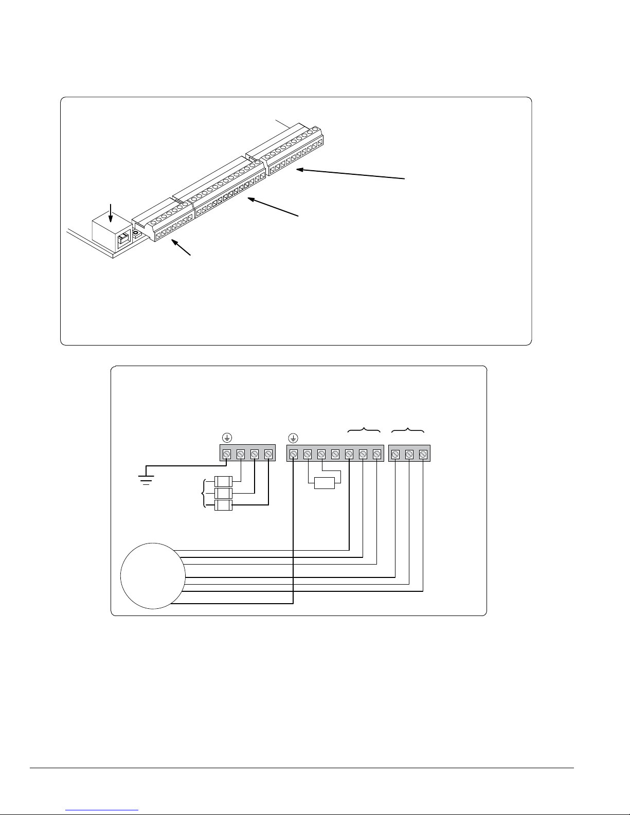
Figure 1-1 Minimum Connection Diagram
Minimum Signal Connections
USB Port
J2
8
J1
1
Terminals 1 to 7 (J1)
1 User Analog Return
2 Analog Input #1
3 Analog Ref. Power
4 Analog Input #2 +
5 Analog Input #2 6 Analog Output #1
7 Analog Output #2
For keypad operation, only Enable (J2-8) is required.
AC Power & Motor Connections
Example of Terminal Strip Layout
J3
Terminals 21 to 30 (J3)
21 External User +24V Return
21
Terminals 8 to 20 (J2)
8 Enable Input
9 Digital Input #1
10 Digital Input #2
11 Digital Input #3
12 Digital Input #4
13 Digital Input #5
14 Digital Input #6
15 Digital Input #7
22 External User +24V
23 Internal +24V
24 Internal +24V Return
25 Relay Out 1 NC
26 Relay Out 1 COM
27 Relay Out 1 NO
28 Relay Out 2 NC
29 Relay Out 2 COM
30 Relay Out 2 NO
16 Digital Input #8
17 Digital Out #1+ (Collector)
18 Digital Out #1- (Emitter)
19 Digital Out #2+ (Collector)
20 Digital Out #2- (Emitter)
Motor Thermal
**
L3L2L1
R1/B+
Motor Leads
Leads*
TH2TH1T3T2T1B-R2
GND
Earth Ground
Motor
Input AC
T1
T2
GND
Power
T3
TH1
TH2
G
Fuses
DB Resistor
(Internal)
Note: The control enable input must be active to allow operation. Therefore, J2-8 Enable is connected by a factory installed
jumper to J3-24. This uses the internal supply and provides an active low at J2-8.
* Remove TH1 and TH2 jumper if Motor Thermal Leads are connected.
Note: Motor thermal leads must be run in a separate conduit from motor power leads.
Note: An open circuit on these terminals will generate a motor overtemperature fault. Refer to the fault / troubleshooting
information provided in Chapter 9.
** See Figure 4-3 for terminal arrangement for the various frame sizes.
1-4 Introduction MN765

Chapter 2
General Information
The VS1GV control uses ux vector technology. Flux vector technology (sometimes referred to as Field Oriented Control) is
a closed loop control scheme that uses an algorithm to adjust the frequency and phase of voltage and current applied to a
three phase induction motor.
The control’s rated output power is based on the use of a NEMA design B four pole motor and 60Hz operation at nominal
rated input voltage. If any other type of motor is used, the control should be sized to the motor using the rated current of
the motor. The control may be used in various applications. It may be programmed by the user to operate in four different
operating zones: standard or quiet and constant torque or variable torque. It can also be congured to operate in a number
of modes depending upon the application requirements and user preference. It is the responsibility of the user to determine
the optimum operating zone and mode to interface the control to the application. These choices are made with the keypad
as explained in Chapter 6 of this manual.
2.1 Limited Warranty
For a period of two (2) years from the date of original purchase, BALDOR will repair or replace without charge controls
and accessories which our examination proves to be defective in material or workmanship. This warranty is valid if the
unit has not been tampered with by unauthorized persons, misused, abused, or improperly installed and has been used
in accordance with the instructions and/or ratings supplied. This warranty is in lieu of any other warranty or guarantee
expressed or implied. BALDOR shall not be held responsible for any expense (including installation and removal),
inconvenience, or consequential damage, including injury to any person or property caused by items of our manufacture
or sale. (Some states do not allow exclusion or limitation of incidental or consequential damages, so the above exclusion
may not apply.) In any event, BALDOR’s total liability, under all circumstances, shall not exceed the full purchase price of the
control. Claims for purchase price refunds, repairs, or replacements must be referred to BALDOR with all pertinent data as to
the defect, the date purchased, the task performed by the control, and the problem encountered. No liability is assumed for
expendable items such as fuses.
Goods may be returned only with written notication including a BALDOR Return Authorization Number and any return
shipments must be prepaid.
2.2 Standards
The VS1GV drives have been designed and tested to comply with the following standards.
2.2.1 Design and Test Standards
• UL508C: Power Conversion Equipment.
• UL840: Insulation coordination including clearance and creepage distances for electrical equipment.
• CSA C22.2 No. 14: Industrial Control Equipment.
• EN61800-5-1: Adjustable speed electrical power drive systems. Safety requirements.
Electrical, thermal and energy.
• EN50178: Electronic equipment for use in power installations.
• EN60529: Degrees of protection provided by enclosures.
• EN61800-3: When installed as directed in this manual, VS1GV drives conform to the category C3 emission limits and the
‘second environment’ immunity requirements dened by this standard.
2.2.2 Environmental Test Standards
• EN60068-1: Environmental testing, general and guidance.
• EN60068-2-2: Environmental testing, Test B. Dry heat.
• EN60068-2-78: Environmental testing, Test cab. Damp heat, steady state.
• EN60068-2-6: Vibration testing.
2.2.3 Marks
See also Appendix C for general recommendations for CE compliance.
General Information 2-1MN765

2-2 General Information MN765

Chapter 3
Installing the Drive
This chapter provides information that must be considered when planning a VS1GV drive installation and provides drive
mounting information and installation site requirements.
3.1 Receiving & Inspection
When you receive your control, there are several things you should do immediately.
1. Observe the condition of the shipping container and report any damage immediately to the commercial carrier that
delivered your control.
2. Remove the control from the shipping container and remove all packing materials from the control. The container and
packing materials may be retained for future shipment.
3. Verify that the catalog number of the control you received is the same as the catalog number listed on your purchase
order.
4. Inspect the control for external physical damage that may have been sustained during shipment and report any damage
immediately to the commercial carrier that delivered your control.
5. If the control is to be stored for several weeks before use, make sure that it is stored in a location that conforms to
published storage humidity and temperature specications stated in this manual.
3.2 General Requirements for the Installation Site
It is important to ensure that the drive’s environment and operating conditions are satisfactory. The area behind the drive
must be kept clear of all control and power wiring. Power connections may create electromagnetic elds that may interfere
with control wiring or components when run in close proximity to the drive.
Read the recommendations in the following sections before continuing with the drive installation.
3.2.1 Location Instructions
Before deciding on an installation site, consider the following guidelines:
• Protect the cooling fan by avoiding dust or metallic particles.
• Do not expose the drive to a corrosive atmosphere.
• Protect the drive from moisture and direct sunlight.
• Verify that the drive location will meet the environmental conditions specied in Table 3-1.
Table 3-1 Ambient Temperatures and Mounting Clearances
Frame Size
AA
B
C
E
F Not Required
Ambient Temperature
Minimum Maximum Top & Bottom Left & Right Sides
45°C
45°C NEMA 1 2 inches (50mm)
-10°C (14°F)
40°C NEMA 4X 0 inches (0mm)
45°C NEMA 1
Enclosure Rating
NEMA 1
NEMA 4X 0 inches (0mm)
3.2.2 Minimum Mounting Clearances
Be sure to provide proper top, bottom and side clearance per Table 3-1.
Minimum Mounting Clearances
2 inches (50mm)
2 inches (50mm)
2 inches (50mm)D
3.3 Mounting the Drive
Mount the drive upright on a at, vertical surface. Avoid mounting the drive in locations that would subject the drive to
vibration in excess of the 0.5G RMS rating (e.g. adjacent to a large punch press).
3.3.1 Protecting the Drive from Debris
Drives suppled in NEMA 1 enclosures must be protected from debris falling through the drive vents during installation and
operation. The drive is designed to operate in NEMA1 Type installations. The atmosphere must not contain airborne particles
that can collect on the internal circuitry of the drive, especially conductive particles. Drives supplied in NEMA 4X enclosures
are designed for harsh environments including dust and water. NEMA 1 and NEMA 4X drives are for indoor use only.
Note: F-Frame Size drives are supplied with door mounted lters that are replaceable. The replacement lter part number
is available on a label next to the lter on the inside of the door. If the user desires, these lters can also be cleaned
by blowing or vacuuming out any collected debris as long as the lter media remains intact. See section 12.2 for
instructions for optionally setting the drive’s real time clock to provide an alert message or output at regular cleaning
intervals.
3.3.2 Watts Loss Data
Frame Size
AA, B, C, D, E and F
Example: At 2.5kHz, a 3hp, 240VAC control draws 10Amps. Watts loss = 50W + (10x14) = 190Watts
2.5kHz PWM 8.0kHz PWM 2.5kHz PWM 8.0kHz PWM 2.5kHz PWM 8.0kHz PWM
50Watts +
(14 W/Amp)
Table 3-2 Watts Loss Data
240VAC 480VAC 600VAC
50Watts +
(17 W/Amp)
50Watts +
(17 W/Amp)
50Watts +
(26 W/Amp)
50Watts +
(18 W/Amp)
Installing the Drive 3-1MN765
50Watts +
(25 W/Amp)
3.4 Cover Removal Procedure (NEMA 1 Drives)
To connect power and signal wires, the cover must be removed (AA, B, C, D and E frame drives). This procedure describes
how to access all terminal connections inside the control.
1. Remove the four cover screws shown in Figure 3-1.
2. Lift and remove the cover.
3. Press in the two Cover Releases (Control) and rotate the control cover open as shown.
4. For E-frame drives, two additional screws must be removed from conduit box to gain access to the power conduit
openings.
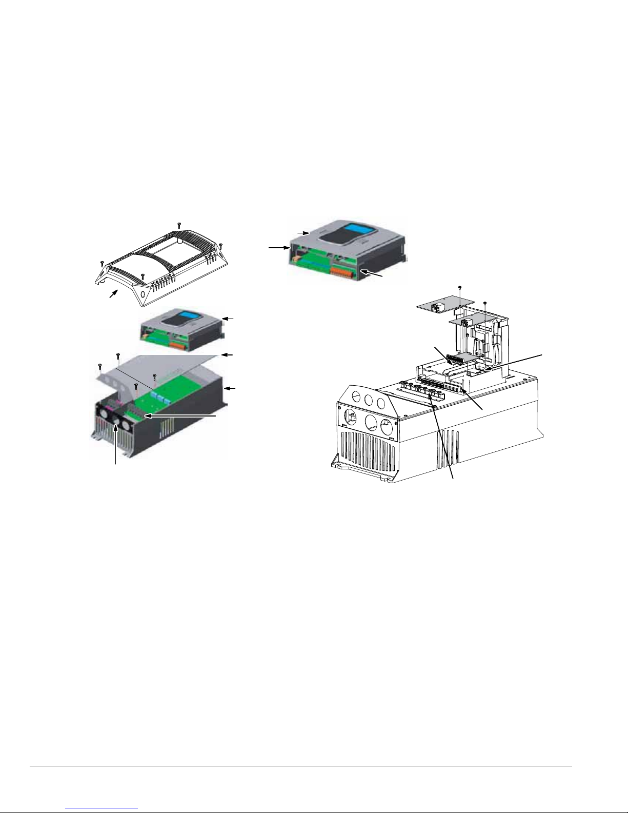
Figure 3-1 Cover Removal
Cover
Screws
(4)
Cover
Shield
Screws
(4)
Cable Entrance
Lift and
remove cover
Cover
Release
Control
Shield
Plate
Power
Base
Power & Motor
Connections
Control
Cover
Cover
Release
I/O Module
Slot 1
I/O Module
Slot 2
Analog/Digital
I/O Terminals
Cable Clamp and
Shield Termination
3.5 Cover Removal Procedure (NEMA 4X Frames AA and B):
CAUTION: Failure to follow this procedure may result in damage to the controller cover gasket which will
cause improper sealing and inability to maintain specified NEMA 4X ratings.
1. While supporting cover, remove all cover screws reserving for usage when replacing cover.
2. Do not use any kind of tool to pry the cover away from the drive to avoid damaging the gasket or surrounding plastic.
3. Separate cover from base a short distance by pulling it away from the drive while being careful to not pull on the keypad
cable which is attached to both the cover and the control board.
4. Disconnect the keypad cable from the keypad board connector on the inside of the cover by pressing in on the retention
clip and gently pulling the cable out of the connector.
3-2 Installing the Drive MN765

3.6 Cover Replacement Procedure (NEMA 4X Frames AA and B):
CAUTION: Failure to follow this procedure may result in damage to the controller cover gasket which will
cause improper sealing and inability to maintain specified NEMA 4X ratings.
1. While holding the cover close to the controller, plug the keypad cable (disconnected in step 4 above) into the connector
on the keypad board making sure that the retention clip snaps into place.
2. Check that keypad cable is not overlapping any of the cover edges while placing cover on drive. Ensure that gasket is
seated in cover groove around the complete perimeter of the cover without any folds.
3. While holding the cover against the base, insert, start and tighten all cover screws and tighten only to the point of contact
with the cover while following the numerical sequence outlined in the diagram below.
4. Using the numerical sequence on the following gure, tighten each screw to 15 in-lbs. of torque.
5. Do not over-tighten ensuring that the cover is seated ush around complete perimeter of base.
Figure 3-2 Cover Replacement (NEMA 4X)
Maximum cover screw torque:
15 in-lbs. (see above procedure)
1
2
Maximum cover screw torque:
15 in-lbs. (see above procedure)
1
3
4
2
3
5
7
9
11
12
4
6
8
10
B - FRAME NEMA 4XAA - FRAME NEMA 4X
Installing the Drive 3-3MN765

3-4 Installing the Drive MN765
Chapter 4
Power Wiring
4.1 Grounding the Drive
Baldor does not recommend using “Grounded Leg Delta” transformer power leads that may create ground loops. Instead
we recommend using a four wire Wye. Baldor drives are designed to be powered from standard three phase lines that are
electrically symmetrical with respect to ground. System grounding is an important step in the overall installation to prevent
problems. The recommended grounding method is shown in Figure 4-1.
Figure 4-1 Recommended System Grounding
Note:
Motor thermal leads must be run in
separate conduit from motor power
leads.
Note:
Wiring shown for clarity of
grounding method only. Not
representative of actual terminal
block arrangement.
An optional separately
Note:
purchased load reactor is
recommended.
See recommended tightening torques in Table A-2.
Note: A line reactor is recommended
and must be purchased separately..
AC Main
Supply
L1
L2
L3
Optional
Line
Reactor
Drive
L1
L2 L3 T1 T2 T3
TH1
TH2
GND
Optional
Load
Reactor
Safety
Ground
Driven Earth
Ground Rod
(Plant Ground)
Four Wire
Wye
Earth
Route all 4 wires L1, L2, L3 and Earth (Ground)
together in conduit or shielded cable.
Route all 4 wires T1, T2, T3 and Motor Ground together
in conduit or shielded cable.
Connect all wires (including motor ground)
inside the motor terminal box.
Ground per NEC and
Local codes.
4.1.1 Ungrounded Distribution System
With an ungrounded power distribution system it is possible to have a continuous current path to ground through the MOV
devices internal to the VS1GV. To avoid equipment damage, an isolation transformer with a WYE grounded secondary is
recommended. This provides three phase AC power that is symmetrical with respect to ground.
4.1.2 Input Power Conditioning
Baldor drives are designed for direct connection to standard three phase lines that are electrically symmetrical with respect
to ground. An AC line reactor or an isolation transformer may be required for some power conditions.
• If the feeder or branch circuit that provides power to the drive has permanently connected power factor correction
capacitors, an input AC line reactor or an isolation transformer must be connected between the power factor correction
capacitors and the drive.
• If the feeder or branch circuit that provides power to the drive has power factor correction capacitors that are switched on
line and off line, the capacitors must not be switched while the drive is connected to the AC power line. If the capacitors
must be switched while the drive is connected to the AC power line, additional protection is required. TVSS (Transient
Voltage Surge Suppressor) of the proper rating must be installed on the drive input between the drive and any type of
input impedance such as an input reactor or drive isolation transformer.
4.2 Line Impedance
Baldor VS1GV drives require 1% line impedance minimum (3% for AA frame size drives and B Frame NEMA 4X drives). If the
impedance of the incoming power does not meet this requirement, a 3 phase line reactor can be used to provide the needed
impedance in most cases. The input impedance of the power lines can be determined as follows:
Measure the line to line voltage at no load and at full rated load.
Use these measured values to calculate impedance as follows:
% Impedance =
Volts Volts
No Load Full Load
Volts
No Load
x 100
Power Wiring 4-1MN765

4.2.1 Line Reactors
Three phase line reactors are available from Baldor. The line reactor to order is based on the full load current of the motor
(FLA). If providing your own line reactor, use the following formula to calculate the minimum inductance required.
X
L =
(I
(V
L- L
X
0.01)
√
X
3
377)
Where:
L Minimum inductance in Henries.
V Input volts measured line to line.
L- L
0.01 Desired percentage of input impedance 1%.
0.03 for AA Frame size drives
I Input current rating of drive.
and for B Frame size NEMA 4X
drives.)
377 Constant used with 60 Hz power.
Use 314 if input power is 50 Hz.
(Note: Change this value to
4.2.2 Load Reactors
Line reactors may be used at the drive output to the motor. When used this way, they are called Load Reactors. Load
reactors serve several functions that include:
• Protect the drive from a short circuit at the motor.
• Limit the rate of rise of motor surge currents.
• Slowing the rate of change of power the drive delivers to the motor.
Load reactors should be installed as close to the drive as possible. Selection should be based on the motor nameplate FLA
value.
4.3 Line Disconnect
A power disconnect should be installed between the input power service and the drive for a fail safe method to disconnect
power. This drive will remain in a powered-up condition until all input power is removed from the drive and the internal bus
voltage is depleted.
4.4 Protective Devices
NOTE: Integral solid state short circuit protection does not provide branch circuit protection. Branch circuit protection must
be provided in accordance with the National Electrical Code and any additional local codes.
Recommended fuse sizes are based on the following:
115% of maximum continuous drive input current for time delay.
150% of maximum continuous drive input current for Fast or Very Fast action.
Note: These recommendations do not consider harmonic currents or ambient temperatures greater than 45°C. Be sure a
suitable input power protection device is installed. Use the recommended fuses and wire sizes shown in Tables
4-1 through 4-6. Wire size is based on the use of copper conductor wire rated at 75°C. The table is specied for
NEMA B motors.
Fast Action Fuses: 240VAC, Buss® KTN
480VAC, Buss® KTS to 600A (KTU for 601 to 1200A)
600VAC, Buss® KTS to 600A (KTU for 601 to 1200A)
Very Fast Action: 240VAC, Buss® JJN
480VAC, Buss® JJS
600VAC, Buss® JJS
Time Delay: 240VAC, BUSS FRN
480VAC, BUSS FRS (KLU for 601 to 1200A)
600VAC, BUSS FRS (KLU for 601 to 1200A)
Semiconductor 240VAC, Ferraz Shawmut A50QS
Fuses: 480VAC, Ferraz Shawmut A70QS
600VAC, Ferraz Shawmut A70QS
UL Listed Breakers: Frame Size D - 250 A maximum (all ratings)
Frame Size E - 300 A maximum for the 150 HP
400 A maximum for the 200 HP
500A maximum for the 250 HP
Frame Size F - 600A maximum for the 300 HP
700A maximum for the 350 HP
750A maximum for the 400 HP
800A maximum for the 450 HP
1000A maximum for the 500 HP
Buss® is a trademark of Cooper Industries, Inc.
4-2 Power Wiring MN765
4.5 Reduced Input Voltage Considerations
When operating with other than nominal input voltages or with non-standard motors, the output current rating of the drive
must be greater than or equal to the continuous load requirements of the motor.
4.6 Electrical Installation
All interconnection wires between the drive, AC power source, motor, host control and any other operator interface stations
should be in metal conduits or shielded cable must be used. If the connection being made is on a connection stud or
grounding screw, then use listed closed loop connectors that are of appropriate size for wire gauge being used. Connectors
are to be installed using crimp tool specied by the manufactuer of the connector. Only Class 1 wiring should be used. See
Figure A-2 in Appendix A for conduit hole size for each frame size.
4.7 Optional Filter/Reactor
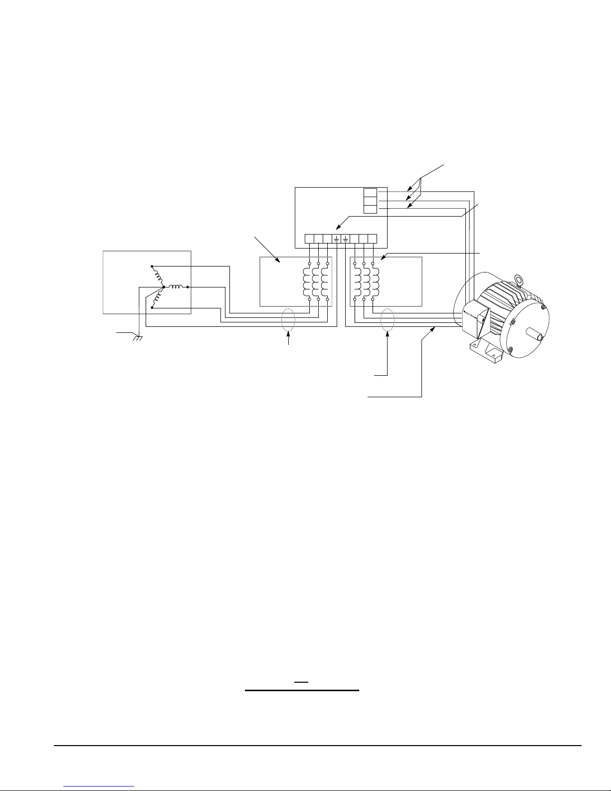
Figure 4-2 shows the connections for installing an optional Line Filter and AC Line Reactor.
Figure 4-2 Filter and Reactor Connections
L1
L2
L3
PE
Control
AC
Line
L2
L3
PE
Line
FilterL1
L1
L2
L3
PE
Load
Reactor
Table 4-1 240VAC Three Phase Wire Size and Protective Devices
Control Rating Input Fuse (Amps) Wire Gauge
HP Input Amps Fast Acting (UL) Fast Acting (CUL) Time Delay Semiconductor (CUL) AWG mm
1 4.2 12 12 9 14 2.5
2 7.0 15 15 12 14 2.5
3 10 25 25 20 14 2.5
5 16 35 35 30 12 4.0
7.5 22 35 35 30 10 6.0
10 28 70 70 60 8 10.0
15 42 80 80 70 6 16.0
20 53 100 100 90 4 25.0
25 66 125 *125 A50QS125-4 4 25.0
30 78 175 *175 A50QS150-4 3 35.0
40 104 175 *175 A50QS150-4 2 50.0
50 130 200 200 175 2/0 70.0
60 154 250 250 200 3/0 85.0
2
*Requires custom drive for CUL application using fast fuses.
Note: Wire sizes based on 75
HP
0
C copper wire. Fuses based on 400C ambient, max continuous output and no harmonic current.
UL Listed Breaker Size
1 20
2 25
3 30
5 40
7.5 50 250
10 60 250
15
Table 4-2 240VAC Three Phase Breaker Size
(AMPS)
HP
UL Listed Breaker Size
(AMPS)
Power Wiring 4-3MN765
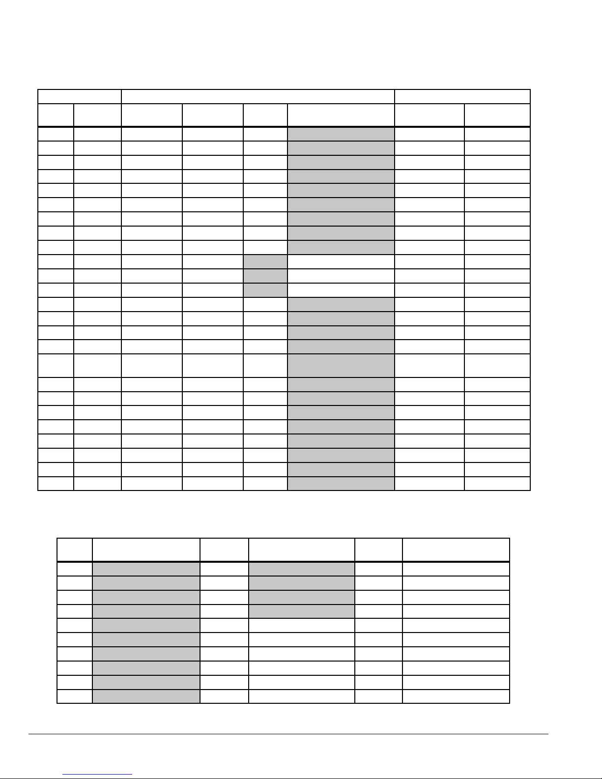
Table 4-3 480VAC Three Phase Wire Size and Protective Devices
Control Rating Input Fuse (Amps) Wire Gauge
HP
Input
Amps
1 2.1 6 6 4.5 14 2.5
2 3.4 8 8 6.3 14 2.5
3 4.8 12 12 10 14 2.5
5 7.6 17.5 17.5 15 14 2.5
7.5 11 25 25 17.5 14 2.5
10 14 25 25 17.5 12 4.0
15 21 40 40 35 10 5.3
20 27 50 50 45 8 10.0
25 34 60 60 50 8 10.0
30 40 80 *80 A70QS60-4 8 10.0
40 52 100 *100 A70QS80-4 6 16.0
50 65 125 *125 A70QS100-4 4 25.0
60 77 125 125 100 3 35.0
75 96 150 150 125 1 50.0
100 124 200 200 175 2/0 70.0
125 156 250 250 200 3/0 85.0
150 180 350 350 300
200 240 450 450 400 Two-3/0 Two-85.0
250 302 600 600 450 Two-250 kcmil Two-127.0
300 361 650 650 450 Two-4/0 Two-110.0
350 414 750 750 550 Two-300 kcmil Two-152.0
400 477 800 800 600 Two-350 kcmil Two-177.0
450 534 900 900 650 Two-400 kcmil Two-203.0
500 590 1000 1000 750 Two-500 kcmil Two-253.0
550 ◊ 650 1000 1000 750 Two-600 kcmil Two-304.0
Fast Acting
(UL)
Fast Acting
(CUL)
Time
Delay
Semiconductor (CUL) AWG mm
One-4/0 or
Two-1/0
One-110.0 or
Two-55.0
2
◊ This rating is applicable when using the VS1GV4500-1T in the SVT (standard variable torque) operating zone.
Table 4-4 480VAC Three Phase Breaker Size
HP
UL Listed Breaker Size
(AMPS)
HP
UL Listed Breaker Size
(AMPS)
HP
1 25 250 500
2 30 250 500
3 40 300 600
5 50 350 700
7.5 60 250 400 750
10 75 250 450 800
15 100 250 500 1000
20 125 250 550 1000
25 150 300
30 200 400
4-4 Power Wiring MN765
UL Listed Breaker Size
(AMPS)

Table 4-5 600VAC Three Phase Wire Size and Protective Devices
Control Rating Input Fuse (Amps) Wire Gauge
HP
Input
Amps
1 1.7 6 6 5 14 2.5
2 2.7 6 6 5 14 2.5
3 3.9 10 10 8 14 2.5
5 6.1 15 15 12 14 2.5
7.5 9.0 17.5 17.5 15 14 2.5
10 11 17.5 17.5 15 14 2.5
15 17 35 35 30 10 6.0
20 22 40 40 35 10 6.0
25 27 50 50 40 8 10.0
30 32 70 *70 A70QS50-4 8 10.0
40 41 80 *80 A70QS70-4 6 16.0
50 52 80 *80 A70QS80-4 6 16.0
60 62 100 100 80 4 25.0
75 77 125 125 100 3 35.0
100 99 150 150 125 1 50.0
125 125 200 200 175 2/0 70.0
150 144 300 300 250 3/0 95.0
200 192 350 350 300
250 242 450 450 400 Two - 3/0 Two - 95
300 289 600 600 450 Two - 4/0 Two - 120
Fast Acting
(UL)
Fast Acting
(CUL)
Time
Delay
Semiconductor (CUL) AWG mm
One - 250 kcmil
or Two - 1/0
150
or Two - 70
2
*Requires custom drive for CUL application using fast fuses.
Note: Wire sizes based on 75
0
C copper wire. Fuses based on 400C ambient, max continuous output and no harmonic current.
Table 4-6 600VAC Three Phase Breaker Size
HP
1 40
2 50
3 60 250
5 75 250
7.5 100 250
10 125 250
15 150 250
20 200 300
25 250 400
30 300 400
UL Listed Breaker Size
(AMPS)
HP
UL Listed Breaker Size
(AMPS)
Power Wiring 4-5MN765

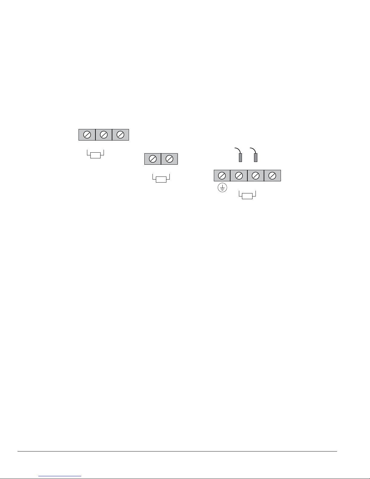
4.8 Incoming Power and Motor Connections
Figure 4-3 shows the layout of the terminals on the power connectors for each size drive. All cables must be in conduits
or shielded and the conduits or shields must be grounded at the cable entrance. The brake resistor and cable must be in a
conduit or shielded if installed outside the enclosure.
Figure 4-3 Power Connections
Frame Size AA 1-Phase Input Drives
GNDNL2L1
R1/B+
Input AC Power
Motor Leads
Dynamic Brake
GND
TH2TH1T3T2T1B-R2
*
Leads
Motor Thermal
Motor
Chassis
Ground
Motor GND
Frame Size B and C Drives
L3L2L1
B+/R1
Input AC Power
Motor Leads
Dynamic Brake
GNDTH2TH1T3T2T1B-R2
Leads *
Motor Thermal
Frame Size E Drives
L3L2
L1
B+/R1
B-R2
GNDTH2TH1
Input AC Power
*
Leads
Ground
Dynamic Brake
Motor Thermal
See recommended tightening torques in Table A-2.
*Remove TH1 to TH2 jumper if Motor Thermal Leads are connected.
Note: An open circuit between TH1 and TH2 will cause an overtemperature fault.
Refer to fault/troubleshooting information in Chapter 9.
T1
T3T2
Motor Leads
Frame Size AA 3-Phase Input Drives
GNDL3L2L1
R1/B+
Motor Leads
Input AC Power
Dynamic Brake
Frame Size D Drives
L3L2
L1
TH2TH1
Ground
Input AC Power
Motor Thermal
Leads
Frame Size F Drives
Note: Thermal lead terminal block mounted
on left side wall.
GND
TH2TH1
Motor Thermal
Leads
*
R1
R2
L1
Dynamic Brake
GND
TH2TH1T3T2T1B-R2
*
Leads
Motor Thermal
B+/R1
GND
L3L2
*
T1
B-R2
Dynamic Brake
Motor Leads
Input AC Power
T3T2
T1
Ground
Motor
Chassis
Ground
Motor GND
T3T2
Motor Leads
1. Access the Power and Motor Terminals (see Cover Removal procedure).
2. Feed the power supply and motor cables into the drive through the cable entrance.
3. Connect the line L1, L2, L3 and GND to the power terminal connectors, Figure 4-4.
4. Connect motor leads to T1, T2, T3 and GND motor terminal connectors.
Note: H2E-Frame Size, 250HP and 300HP (575V) drives utilize studs for power terminations.
4-6 Power Wiring MN765

Figure 4-4 3-Phase Input Power Connections
*Optional components not provided with control.
1. See “Protective Devices” described previously in this section.
2. Use same gauge wire for Earth ground as is used for L1, L2
and L3 for AA, B, C frame drives. For D, E and F frame drives,
size the grounding conductor per the local electrical codes.
3. Metal conduit should be used. Connect conduits so the
use of a Reactor or RC Device does not interrupt
EMI/RFI shielding.
4. See Line/Load Reactors described previously in this section.
Note 1
Note 3
Note 4
*Fuses
*Optional
Line
L1 L2 L3
A1 B1 C1
Reactor
A2 B2 C2
Note 3
L1 L2 L3
Baldor
Control
4.9 Operating a 3-Phase Control on Single Phase Input Power
Single phase AC input power can be used to power the control instead of three phase for control sizes AA, B and C. The
specications and control sizes are listed in Appendix A of this manual. If single phase power is to be used, the rated
Horsepower of the control must be reduced (derated). In addition, power wiring and jumper changes are required. Both
connection types are shown in Figures 4-5 and 4-6.
Single phase rating wire size and protection devices are listed in Tables 4-7 and 4-8.
Earth
Note 2
GND
4.9.1 Single Phase Power Derating:
Single phase power derating requires that the continuous and peak current ratings of the control be reduced by the
following:
1. 1 - 7.5HP 240 and 480VAC controls:
Derate output hp to the next lower hp value (i.e. 7.5hp becomes 5hp, etc.)
2. 10 - 50HP 240 and 480VAC controls:
Derate output hp by 50% of the nameplate rating.
Table 4-7 Single Phase Wire Size and Protection Devices - 240VAC Controls
Drive
HP
2 1 8.0 12 12 14 2.5
3 2 10 20 20 14 2.5
5 3 15 25 25 12 4.0
7.5 5 28 45 45 10 6.0
10 5 28 45 45 12 4.0
15 7.5 40 60 60 8 10.0
20 10 50 80 80 6 16.0
25 10 50 80 *80 A50QS125-4 6 16.0
30 15 68 100 *100 A50QS150-4 4 25.0
40 20 88 125 *125 A50QS150-4 3 35.0
Derated Rating Input Fuse (Amps) Wire Gauge
HP Input Amps Fast Acting (UL) Fast Acting (CUL) Semiconductor (CUL) AWG mm
2
*Requires custom drive for CUL application using fast fuses.
Note: Wire sizes based on 75
0
C copper wire. Fuses based on 400C ambient, max continuous output and no harmonic current.
Power Wiring 4-7MN765
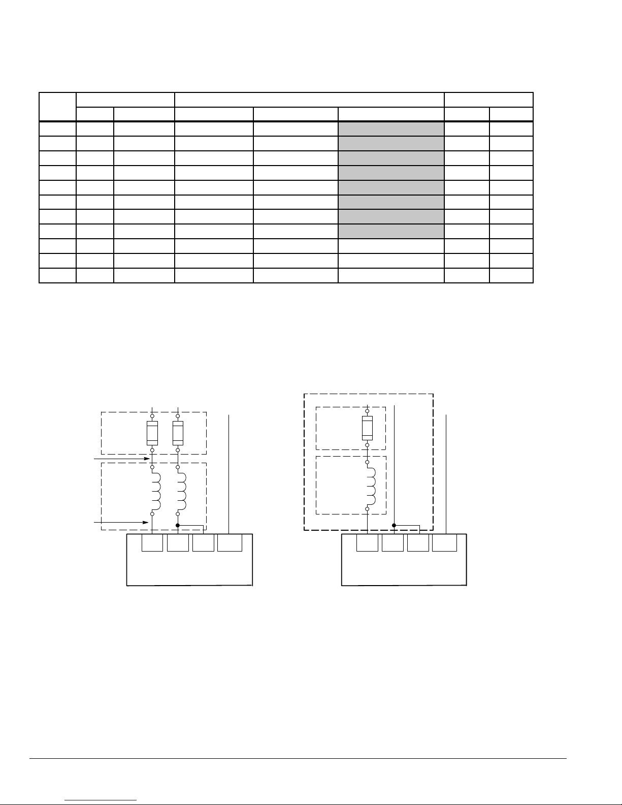
Table 4-8 Single Phase Wire Size and Protection Devices - 480VAC Controls
Drive
HP
2 1 4.0 6 6 14 2.5
3 2 6.0 10 10 14 2.5
5 3 8.5 15 15 14 2.5
7.5 5 14 20 20 14 2.5
10 5 14 20 20 14 2.5
15 7.5 20 30 30 12 4.0
20 10 25 40 40 10 6.0
25 10 25 40 40 10 6.0
30 15 34 50 *50 A70QS50-4 8 10.0
40 20 44 60 *60 A70QS60-4 8 10.0
50 25 55 80 *80 A70QS80-4 6 16.0
Derated Rating Input Fuse (Amps) Wire Gauge
HP Input Amps Fast Acting (UL) Fast Acting (CUL) Semiconductor (CUL) AWG mm
2
*Requires custom drive for CUL application using fast fuses.
Note: Wire sizes based on 75
0
C copper wire. Fuses based on 400C ambient, max continuous output and no harmonic current.
Frames D, E and F drives cannot be applied with a single phase power source.
Figure 4-5 Size AA Single Phase Power Connections to a 3-Phase Control
Single Phase 2 Wire ConnectionsSingle Phase 3 Wire Connections
L1 L2
Note 1
Note 3
Note 4
Note 3
*
Optional components are not provided with control.
See Recommended Tightening Torques in Table A-2.
*Fuses
A1 B1
*Optional
Line
Reactor
A2 B2
L1 L2 L3
Baldor
Control
Earth
GND
Note 2
*Fuse
*Optional
Line
Reactor
Notes:
1.
See Protective Devices described previously in this section.
2. Use same gauge wire for Earth ground as is used for L1 and L2.
3. Metal conduit should be used. Connect conduits so the use of
a Reactor or RC Device does not interrupt EMI/RFI shielding.
4. See Line/Load Reactors described previously in this section.
Line Reactors are built-in for size B and larger controls.
L1
Neutral
A1
A2
L1 L2 L3
Baldor
Control
Earth
In order to protect the drive,
Level 2, Drive Configure, Power
Input P2110 should be set to
“Single Phase”.
GND
4-8 Power Wiring MN765

Figure 4-6 Size B and C Single Phase Power Connections to a 3-Phase Control
Single Phase 2 Wire ConnectionsSingle Phase 3 Wire Connections
L1
L1 L2
Earth
Neutral
Earth
Note 1
Note 3
Note 4
Note 3
*Fuses
*Optional
Line
Reactor
A1 B1
A2 B2
L1 L2 L3
Baldor
Control
Note 2
IMPORTANT:
Do not connect L3.
GND
*Fuse
A1
*Optional
Line
Reactor
A2
L1 L2 L3
Baldor
Control
In order to protect the drive,
Level 2, Drive Configure, Power
Input P2110 should be set to
“Single Phase”.
IMPORTANT:
Do not connect L3.
GND
Notes:
1.
See Protective Devices described previously in this section.
*Optional components not provided with control.
See recommended tightening torques in Table A-2.
2. Use same gauge wire for Earth ground as is used for L1 and L2.
3. Metal conduit should be used. Connect conduits so the use of a
Reactor or RC Device does not interrupt EMI/RFI shielding.
4. See Line/Load Reactors described previously in this section.
Line Reactors are built-in for size B and larger controls.
Single Phase Power and Motor Connections VS1GV6XX-XX
Figure 4-7 shows the minimum connections required at the power connector. All cables must be in conduits or shielded
and the conduits or shields must be grounded at the cable entrance. The brake resistor and cable must be in a conduit or
shielded if installed outside the enclosure.
Figure 4-7 Single Phase Control Power Terminals
Frame Size AA
GNDNL2L1
R1/B+
Input AC
Power
Dynamic
Brake
Motor
Leads
See recommended tightening torques in Table A-2.
TH2TH1T3T2T1 B-R2
GND
*
Leads
Motor Thermal
Motor GND
Motor
Chassis
Ground
*Remove TH1 to TH2 jumper if Motor Thermal Leads are connected.
Note: An open circuit between TH1 and TH2 will be used by the drive to generate a motor overtemperature fault. Refer to
the fault/troubleshooting information provided in Chapter 9.
1. Access the Power and Motor Terminals (see Cover Removal procedure).
2. Feed the power supply and motor cables into the drive through the cable entrance.
3. Connect the line L1, L2, N and GND to the power terminal connections, Figure 4-7.
4. Connect motor leads to T1, T2, T3 and GND motor terminal connectors.
Power Wiring 4-9MN765
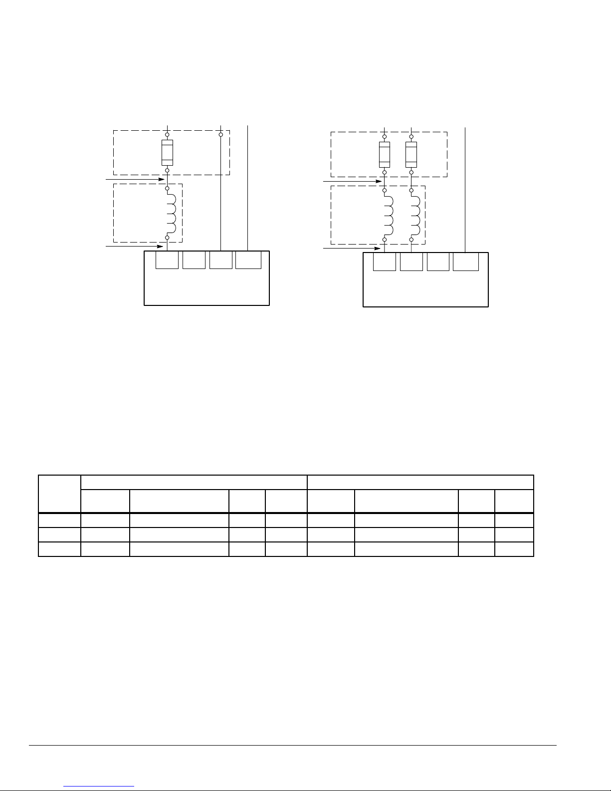
Figure 4-8 Single Phase Power Control Connections
Note 1
Note 3
Note 4
Note 3
120VAC Single Phase
L1 N
*Fuses
A1
*Optional
Line
Reactor
A2
L1 L2 N
Baldor
Control
Earth
GND
Note 2
Note 1
Note 3
Note 4
Note 3
240VAC Single Phase
*Fuses
A1 B1
*Optional
Line
Reactor
A2 B2
L1 L2
L1 L2 N
Baldor
Control
Earth
Note 2
GND
See recommended tightening torques in Table A-2.
*Optional components not provided with control.
NOTES:
1. See Table 4-6.
2. Use same gauge wire for Earth ground as is used for L1, L2 and N.
3. Metal conduit should be used. Connect conduits so the use of a reactor or RC Device does not interrupt EMI/RFI
shielding.
4. See Line/Load Reactors described previously in this section.
Table 4-9 Single Phase Rating Wire Size and Protection Devices - 120/240VAC Controls
120VAC Single Phase Input 240VAC Single Phase Input
HP
Input
Amps
Input Fuse (Amps)
Fast Acting
AWG mm
1 12 20 12 4.0 6.3 12 14 2.5
2 20 30 10 6.0 10.2 20 14 2.5
3 30 35 10 6.0 14.4 25 12 4.0
0
Note: All wire sizes are based on 75
C copper wire. Recommended fuses are based on 400C ambient, maximum continuous
control output and no harmonic current.
Input
2
Amps
Input Fuse (Amps)
Fast Acting
AWG mm
2
4-10 Power Wiring MN765
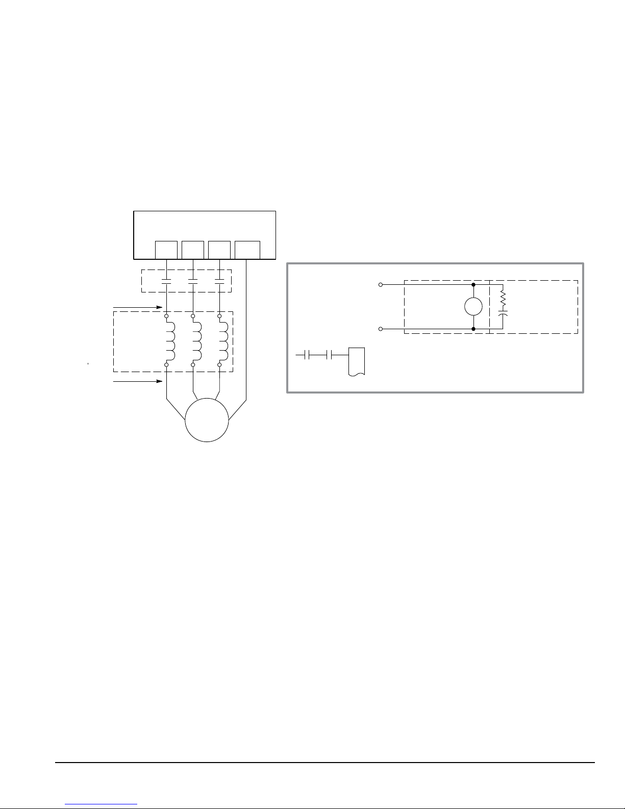
4.10 M-Contactor
If required by local codes or for safety reasons, an M-Contactor (motor circuit contactor) may be installed. However,
incorrect installation or failure of the M-Contactor or wiring may damage the control. M-Contactor connections are shown
in Figure 4-9.
CAUTION: If an M-Contactor is installed, the control must be disabled for at least 200msec before the
M-Contactor is opened. If the M-Contactor is opened while the control is supplying voltage and
current to the motor, the control may be damaged. Before the control is enabled, the M-Contactor
must be closed for at least 200msec.
Figure 4-9 Motor Connections and Optional Connections
Baldor
Control
Note 1
Note 2
Note 1
T1 T2 T3
M
A1 B1 C1
*Optional
Load
Reactor
A2 B2 C2
T2 T3
T1
G
* AC Motor
GND
Note 3
*Optional M Contactor Connections
To Power Source
(Rated Coil Voltage)
*
M Enable
*M=Aux Contacts of optional M-Contactor
See recommended tightening torques in Table A-2.
*Optional components not provided with control.
J2
8
9
* M-Contactor
* Optional
M
RC Device
Electrocube
RG1781-3
NOTES:
1. Metal conduit should be used. Connect conduits so the use of the Load Reactor or RC Device does not interrupt EMI/RFI
shielding.
2. See Line/Load Reactors described previously in this section.
3. Use same gauge wire for ground as for T1, T2 and T3 for AA, B, and C controls. For size D, E and F controls, size the
grounding conductor per the local electrical code.
4.11 Long Motor Leads
The wire leads that connect the motor to the control are critical in terms of sizing, shielding and the cable characteristics.
Short cable runs are usually trouble free but fault-monitoring circuitry can produce numerous faults when long cables (over
100 feet) are used.
• 100+ft (30m): Baldor recommends adding an optional load reactor to the output of the control.
• 250+ft (75m): Baldor recommends adding and optional load reactor and common mode choke to the control.
The load reactor and/or common mode choke should be placed in close physical proximity to the control. Unexpected
faults may occur due to excessive charging current required for motor cable capacitance. If you use long motor leads and
experience unexpected trips due to overload conditions and are not sure how to correctly size and connect the optional
load reactors, please contact your Baldor representative.
Power Wiring 4-11MN765
4.12 Optional Dynamic Brake Hardware
Refer to Figure 4-10 for DB resistor connections. Dynamic Brake (DB) hardware must be installed on a at, non-ammable,
vertical surface for effective cooling and operation.
CAUTION: Before external Dynamic Brake Hardware is added, the internal resistor must be disconnected
(frames AA, B, C and D). Remove the resistor from the B+/R1 and R2 terminals. The external
resistor can be connected across these terminals. Failure to remove the internal resistor
will decrease the total resistance (parallel connection) and cause damage.
Figure 4-10 DB Terminal Identification
AA, B - NEMA 1, D and E Sizes
“1B”
B -
External
R2
F Size
R1
External
R2
B+ / R1
See recommended tightening torques in Table A-2.
B - NEMA 4X and C Size Only Disconnect Internal
DB resistor wires from DBR1 and DBR2 terminals
before connecting external DB Resistor to prevent damage.
DBR2
DBR1
TB101
R2
B+ / R1
B -
External
NOTES:
1. Wires from the internal Dynamic Brake resistor for size AA, B, C and D controls must be removed before external resistor
hardware is installed.
2. E and F size drives up to 450 HP do not include an internal Dynamic Brake resistor but do include the transistor.
3. Although not shown, metal conduit should be used to shield all power wires and motor leads.
4-12 Power Wiring MN765
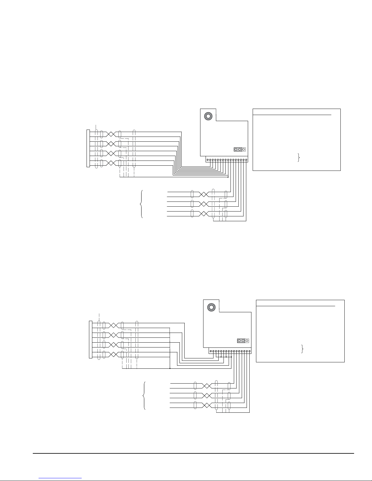
4.13 Encoder Installation
The Encoder Board (Daughter FDBK) is installed in the Feedback Module Slot 3 shown in Figure 4-11. Encoder
connections are made at that board. Use 16AWG (1.31mm2) maximum. The Encoder Board can provide +5VDC or
+12VDC (jumper selectable) encoder power. The factory setting for this jumper is +5VDC power. If an external
power supply is used for encoder power, the J1 jumper must still be used to scale the input signal levels correctly.
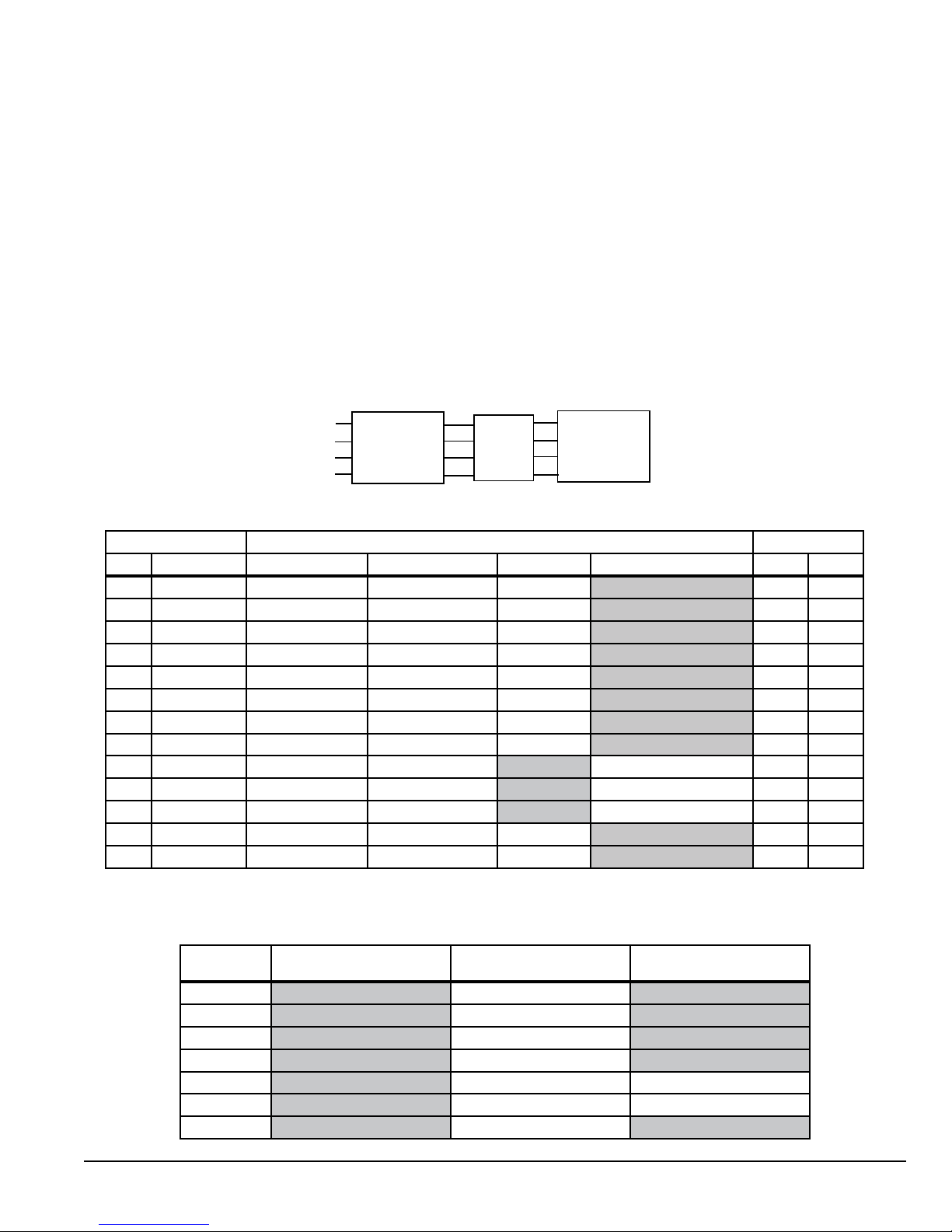
Figure 4-11 Differential Encoder Connections
J1 Pins
Power Source
1-2 5VDC
2-3 12VDC
1
Encoder
Connector
Channel A+
Channel A -
Channel B+
Channel BChannel C+
Channel C-
Encoder Power +
Encoder Power -
J1 selects the power source for the encoder
16-22AWG Twisted Pair
A
H
B
J
C
K
D
F
Grey
Violet
Yellow
Orange
Blue
Green
White
Black
Shield
Channel A+
Channel AChannel B+
Channel BChannel C+
Channel C-
Encoder Output
Encoder
Board
Chassis
GND
1
16-22AWG Twisted Pair
Important: An isolated power supply provides encoder power. Do not connect encoder Power to encoder case. Encoder
performance will be compromised.
Single Ended Connections
Differential inputs are recommended for best noise immunity. If only single ended encoder signals are available, connect
them to A+, B+, and INDEX (C+) (2, 4, and 6 respectively). A-, B- and C- are then connected to common at 9 as shown in
Figure 4-12.
Encoder Board Connections
Pin Signal (In) Pin Signal (Out)
1 Chassis GND
2A+
3A4B+
J1
5B6C+
7C-
16
8 Encoder Power +
9 Encoder Power -
16 = Outer Shield
Connect all cable shields to pin 1 or 16.
For single ended encoder connections, connect
all unused inputs to pin 9. Pin 9 is an isolated
ground, do not connect to any other ground.
See recommended tightening torques in Table A-2.
10 CH A+
11 CH A12 CH B+
13 CH B14 CH C+
15 CH C-
Chassis Ground
16
Isolated Power
Supply Output
Figure 4-12 Single Ended Encoder Connections
J1 Pins
J1 selects the power source for the encoder
Encoder
Connector
Channel A+
Channel B+
Channel C+
Encoder Power+
Encoder Power-
*If these wires are present in cable, they need to be
connected to terminal 9.
A
H
B
J
C
K
D
F
16-22AWG Twisted Pair
Grey
Violet*
Yellow
Orange*
Blue
Green*
White
Black
Shield
Channel A+
Channel A-
Channel B+
Channel B-
Channel C+
Channel C-
Encoder Output
Encoder
Chassis
GND
1
16-22AWG Twisted Pair
Power Source
1-2 5VDC
2-3 12VDC
Board
1
Important: An isolated power supply provides encoder power. Do not connect encoder Power to encoder case. Encoder
performance will be compromised.
Encoder Board Connections
Pin Signal (In) Pin Signal (Out)
1 Chassis GND
2A+
3A4B+
J1
5B6C+
7C-
16
8 Encoder Power +
9 Encoder Power -
16 = Outer Shield
Connect all cable shields to pin 1 or 16.
For single ended encoder connections, connect
all unused inputs to pin 9. Pin 9 is an isolated
ground, do not connect to any other ground.
See recommended tightening torques in Table A-2.
10 CH A+
11 CH A12 CH B+
13 CH B14 CH C+
15 CH C-
Chassis Ground
16
Isolated Power
Supply Output
Power Wiring 4-13MN765
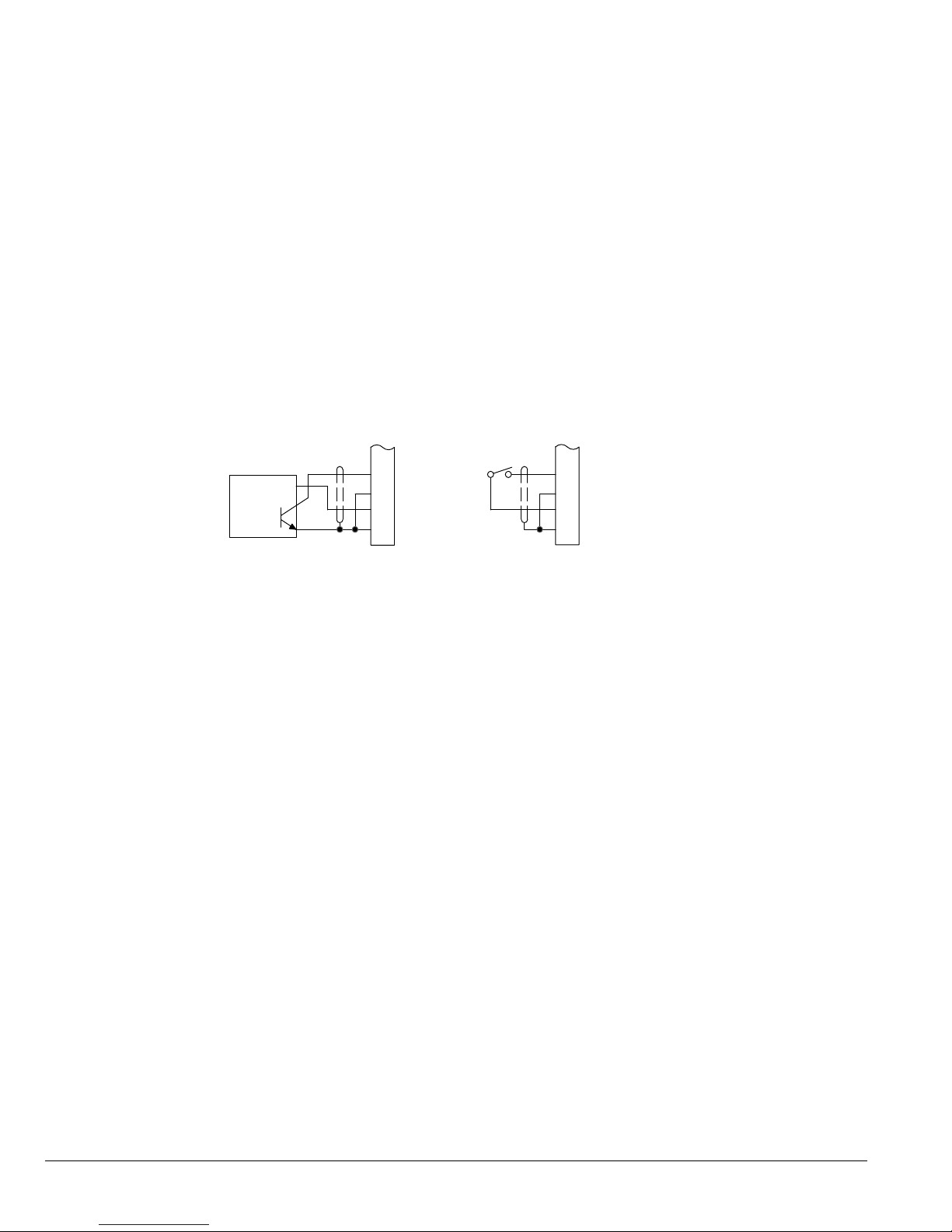
4.14 Home (Orient) Switch Input
The Home or Orient function causes the motor shaft to rotate to a predened home position {Home + Offset} (where
offset can be a “+” or “-” value). The homing function allows shaft rotation in the drive forward direction only until the
rising edge of the signal edge at terminal J2-6 of the encoder daughter board. The home position is located when a
machine mounted switch or the encoder C “Index” pulse is activated (closed). Home switch position is dened by a rising
signal edge at terminal J2-6 of the encoder daughter board. The shaft will continue to rotate in either direction to the user
dened offset value. The offset is programmed in the Level 2 Miscellaneous Homing Offset parameter (P#2308). The speed
at which the motor will “Home” or orient is set with the Level 2 Miscellaneous Homing Speed parameter (P#2307).
A machine mounted switch may be used to dene the Home position in place of the encoder index channel. A differential
line driver output from a solid state switch is preferred for best noise immunity. Connect this differential output to terminals
J2-6 and J2-7.
A single ended solid-state switch should be wired as shown in Figure 4-13. Regardless of the type of switch used, clean
rising and falling edges at J2-6 are required for accurate positioning.
NOTE: A control may require dynamic brake hardware for Orient (Homing) function to work. The control may trip without
dynamic brake hardware installed.
Figure 4-13 Typical Home or Orient Switch Connections (Encoder Board)
+5V Input
Output
Common
5VDC Proximity Switch
See recommended tightening torques in Table A-2.
J2
6
7
8
9
C+
C
+5V
Common
J2
6
C+
7
C
8
+5V
9
Common
Limit Switch (Closed at HOME)
4-14 Power Wiring MN765
 Loading...