


ZD18H201–E
Baldor ZD18H201–E, ZD18H401–E, ZD18H501–E, ZD18H201–W, ZD18H401–W Installation & Operating Manual
...
VECTOR DRIVE
AC Flux Vector Control
SERIES 18H
Installation
9/97 MN718
& Operating Manual

Table of Contents
Section 1
Quick Start Guide
Overview 1-1
Quick
Quick
Section
General Information 2-1.
Section
Receiving & Installation
2
Overview 2-1
Limited Warranty 2-2.
Safety
Notice
3
Receiving
Physical
Control
Through
Optional
Electrical
Input
AC
Wire
AC
Optional
Encoder
Home
Buffered
Location
Installation
the W
Remote Keypad Installation
Installation
System
Line
Impedance
Line Reactors 3-7.
Load Reactors 3-7.
Current Requirements
Main Circuit
Protection Devices 3-10.
Power
Size and Protection Devices
Line Connections
380-400 VAC Configuration
Three
Single
Single
Size
A and B Single Phase Power Installation
Size
C and D Single Phase Power Installation
Size
E Single Phase Power Installation
Size
F Single Phase Power Installation
Dynamic Brake Hardware
Physical
Electrical
Installation
(Orient) Switch Input
Encoder Output
. . . . . . . . . . . . . . . . . . . . . . . . . . . . . . . . . . . . . . . . . . . . . . . . . . . . . . . . . . . . . . . . . . . . . . . . . . . . . . .
. . . . . . . . . . . . . . . . . . . . . . . . . . . . . . . . . . . . . . . . . . . . . . . . . . . . . . . . . . . . . . . . . . . . . . . . . . . . . . . . . . . .
Start Checklist
Start Procedure
. . . . . . . . . . . . . . . . . . . . . . . . . . . . . . . . . . . . . . . . . . . . . . . . . . . . . . . . . . . . . . . . . . . . . . . . . . . . .
. . . . . . . . . . . . . . . . . . . . . . . . . . . . . . . . . . . . . . . . . . . . . . . . . . . . . . . . . . . . . . . . . . . . . . . . . . . . . . . . . . . .
. . . . . . . . . . . . . . . . . . . . . . . . . . . . . . . . . . . . . . . . . . . . . . . . . . . . . . . . . . . . . . . . . . . . . . . . . . . . .
. . . . . . . . . . . . . . . . . . . . . . . . . . . . . . . . . . . . . . . . . . . . . . . . . . . . . . . . . . . . . . . . . . . . . . . . . . . . . . . .
& Inspection
. . . . . . . . . . . . . . . . . . . . . . . . . . . . . . . . . . . . . . . . . . . . . . . . . . . . . . . . . . . . . . . . . . . . . . . . . . . .
. . . . . . . . . . . . . . . . . . . . . . . . . . . . . . . . . . . . . . . . . . . . . . . . . . . . . . . . . . . . . . . . . . . . . . . . . . .
all Mounting
Grounding
. . . . . . . . . . . . . . . . . . . . . . . . . . . . . . . . . . . . . . . . . . . . . . . . . . . . . . . . . . . . . . . . . . . . . . . . . . .
. . . . . . . . . . . . . . . . . . . . . . . . . . . . . . . . . . . . . . . . . . . . . . . . . . . . . . . . . . . . . . . . . . . . . . . . . . .
. . . . . . . . . . . . . . . . . . . . . . . . . . . . . . . . . . . . . . . . . . . . . . . . . . . . . . . . . . . . . . . . . . . . . . . . . . . . . .
Disconnect
Phase Input Power
Phase Input Power Considerations
Phase Control Derating
Installation
Installation
. . . . . . . . . . . . . . . . . . . . . . . . . . . . . . . . . . . . . . . . . . . . . . . . . . . . . . . . . . . . . . . . . . . . .
. . . . . . . . . . . . . . . . . . . . . . . . . . . . . . . . . . . . . . . . . . . . . . . . . . . . . . . . . . . . . . . . . . . .
. . . . . . . . . . . . . . . . . . . . . . . . . . . . . . . . . . . . . . . . . . . . . . . . . . . . . . . . . . . . . . . . . . . . . . . . . .
. . . . . . . . . . . . . . . . . . . . . . . . . . . . . . . . . . . . . . . . . . . . . . . . . . . . . . . . . . . . . . . . . . . . . . . .
. . . . . . . . . . . . . . . . . . . . . . . . . . . . . . . . . . . . . . . . . . . . . . . . . . . . . . . . . . . . . . . . . . . .
. . . . . . . . . . . . . . . . . . . . . . . . . . . . . . . . . . . . . . . . . . . . . . . . . . . . . . . . . . . .
. . . . . . . . . . . . . . . . . . . . . . . . . . . . . . . . . . . . . . . . . . . . . . . . . . . . . . . . . . . . . . . . . . . . . . . . . .
. . . . . . . . . . . . . . . . . . . . . . . . . . . . . . . . . . . . . . . . . . . . . . . . . . . . . . . . . . . . . . . . . . . . . . .
. . . . . . . . . . . . . . . . . . . . . . . . . . . . . . . . . . . . . . . . . . . . . . . . . . . . . . . . . . . . . . . . . . . . . . . . .
. . . . . . . . . . . . . . . . . . . . . . . . . . . . . . . . . . . . . . . . . . . . . . . . . . . . . . . . . . . . . . . . . . .
. . . . . . . . . . . . . . . . . . . . . . . . . . . . . . . . . . . . . . . . . . . . . . . . . . . . . . . . . . . . . . . . . . . . . . .
. . . . . . . . . . . . . . . . . . . . . . . . . . . . . . . . . . . . . . . . . . . . . . . . . . . . . . . . . . . . . . . . . . . . . . . .
. . . . . . . . . . . . . . . . . . . . . . . . . . . . . . . . . . . . . . . . . . . . . . . . . . . . . . . . . . . . . .
. . . . . . . . . . . . . . . . . . . . . . . . . . . . . . . . . . . . . . . . . . . . . . . . . . . . . . . . . . . . . . . . . . . . . . . . .
. . . . . . . . . . . . . . . . . . . . . . . . . . . . . . . . . . . . . . . . . . . . . . . . . . . . . . . . . . . . . . .
. . . . . . . . . . . . . . . . . . . . . . . . . . . . . . . . . . . . . . . . . . . . . . . . . . . . . . . . . . . . . . . . .
. . . . . . . . . . . . . . . . . . . . . . . . . . . . . . . . . . . . . . . . . . . . . . . . . . .
. . . . . . . . . . . . . . . . . . . . . . . . . . . . . . . . . . . . . . . . . . . . . . . . . . . . . . . . . . . . .
. . . . . . . . . . . . . . . . . . . . . . . . . . . . . . . . . . . . . . . . . . . . . . . .
. . . . . . . . . . . . . . . . . . . . . . . . . . . . . . . . . . . . . . . . . . . . . . . .
. . . . . . . . . . . . . . . . . . . . . . . . . . . . . . . . . . . . . . . . . . . . . . . . . . . . .
. . . . . . . . . . . . . . . . . . . . . . . . . . . . . . . . . . . . . . . . . . . . . . . . . . . . . .
. . . . . . . . . . . . . . . . . . . . . . . . . . . . . . . . . . . . . . . . . . . . . . . . . . . . . . . . . . . . .
. . . . . . . . . . . . . . . . . . . . . . . . . . . . . . . . . . . . . . . . . . . . . . . . . . . . . . . . . . . . . . . . . . . . . .
. . . . . . . . . . . . . . . . . . . . . . . . . . . . . . . . . . . . . . . . . . . . . . . . . . . . . . . . . . . . . . . . . . . . .
. . . . . . . . . . . . . . . . . . . . . . . . . . . . . . . . . . . . . . . . . . . . . . . . . . . . . . . . . . . . . . . . . . . . . . . . . .
. . . . . . . . . . . . . . . . . . . . . . . . . . . . . . . . . . . . . . . . . . . . . . . . . . . . . . . . . . . . . . . . . . . .
. . . . . . . . . . . . . . . . . . . . . . . . . . . . . . . . . . . . . . . . . . . . . . . . . . . . . . . . . . . . . . . . . . . . . .
1-1.
1-1.
1-2.
2-3.
3-1.
3-1.
3-1.
3-2.
3-2.
3-3.
3-4.
3-4.
3-6.
3-9.
3-10.
3-10.
3-10.
3-13.
3-13.
3-15.
3-18.
3-18.
3-18.
3-20.
3-22.
3-24.
3-26.
3-26.
3-27.
3-30.
3-32.
3-32.
MN718
Table
of Contents i

Section 1
General Information
Control Circuit Connections
Keypad
Standard
15
Fan
Fan
Bipolar
Process
Specific
Analog
Analog
Analog
External T
Opto-Isolated
Opto-Isolated
Pre-Operation
Power-Up
Section
Programming and Operation 4-1.
4
Overview 4-1
Display
Adjusting
Display
Display
Fault Log Access 4-5.
Program
Parameter
Changing
Reset
Initialize
Parameter
Mode Connections
Run 3 Wire Mode Connections
Speed 2-Wire Mode Connections
Pump 2 Wire Control Mode
Pump 3 Wire Control Mode
Speed and T
Mode Connections
Process Mode Outputs
Inputs and Outputs
Inputs
Outputs
rip Input
Inputs
Outputs
Procedure
. . . . . . . . . . . . . . . . . . . . . . . . . . . . . . . . . . . . . . . . . . . . . . . . . . . . . . . . . . . . . . . . . . . . . . . . . . . . . . . . . . . .
Mode
Mode Screens
Screens & Diagnostic Information Access
Mode
Parameters to Factory Settings
New Firmware
Definitions
. . . . . . . . . . . . . . . . . . . . . . . . . . . . . . . . . . . . . . . . . . . . . . . . . . . . . . . . . . . . . . . . . . . . . . . . . . .
. . . . . . . . . . . . . . . . . . . . . . . . . . . . . . . . . . . . . . . . . . . . . . . . . . . . . . . . . . . . . . . . . . . . . . . . . .
. . . . . . . . . . . . . . . . . . . . . . . . . . . . . . . . . . . . . . . . . . . . . . . . . . . . . . . . . . . . . . . . . . . . . . . . . . . .
. . . . . . . . . . . . . . . . . . . . . . . . . . . . . . . . . . . . . . . . . . . . . . . . . . . . . . . . . . . . . . . . . . . . . . . . . .
Checklist
. . . . . . . . . . . . . . . . . . . . . . . . . . . . . . . . . . . . . . . . . . . . . . . . . . . . . . . . . . . . . . . . . . . . . . . . . . . . . . . .
Display Contrast
. . . . . . . . . . . . . . . . . . . . . . . . . . . . . . . . . . . . . . . . . . . . . . . . . . . . . . . . . . . . . . . . . . . . . . . . . . . . . . .
Blocks Access for Programming
Parameter V
. . . . . . . . . . . . . . . . . . . . . . . . . . . . . . . . . . . . . . . . . . . . . . . . . . . . . . . . . . . . . . . . . . . .
. . . . . . . . . . . . . . . . . . . . . . . . . . . . . . . . . . . . . . . . . . . . . . . . . . . . . . . . . . . . . . . .
. . . . . . . . . . . . . . . . . . . . . . . . . . . . . . . . . . . . . . . . . . . . . . . . . . . .
. . . . . . . . . . . . . . . . . . . . . . . . . . . . . . . . . . . . . . . . . . . . . . . . . . . . . . . .
. . . . . . . . . . . . . . . . . . . . . . . . . . . . . . . . . . . . . . . . . . . . . . . . . . . . . . . . . . . .
. . . . . . . . . . . . . . . . . . . . . . . . . . . . . . . . . . . . . . . . . . . . . . . . . . . . . . . . . . . .
orque Mode Connections
. . . . . . . . . . . . . . . . . . . . . . . . . . . . . . . . . . . . . . . . . . . . . . . . . . . . . . . . . . . . . . .
. . . . . . . . . . . . . . . . . . . . . . . . . . . . . . . . . . . . . . . . . . . . . . . . . . . . . . . . . . . .
. . . . . . . . . . . . . . . . . . . . . . . . . . . . . . . . . . . . . . . . . . . . . . . . . . . . . . . . . . . . . . . . . . . .
. . . . . . . . . . . . . . . . . . . . . . . . . . . . . . . . . . . . . . . . . . . . . . . . . . . . . . . . . . . . . . . . . . . . . . . .
. . . . . . . . . . . . . . . . . . . . . . . . . . . . . . . . . . . . . . . . . . . . . . . . . . . . . . . . . . . . . . . . . . . . . . .
. . . . . . . . . . . . . . . . . . . . . . . . . . . . . . . . . . . . . . . . . . . . . . . . . . . . . . . . . . . . . . . . . . . . . . . . .
. . . . . . . . . . . . . . . . . . . . . . . . . . . . . . . . . . . . . . . . . . . . . . . . . . . . . . . . . . . . . . . . . . . . .
. . . . . . . . . . . . . . . . . . . . . . . . . . . . . . . . . . . . . . . . . . . . . . . . . . . . . . . . . . . . . . . .
. . . . . . . . . . . . . . . . . . . . . . . . . . . . . . . . . . . . . . . . . . . . . . . . . . . . . . . . . . . . . . . . . . . .
. . . . . . . . . . . . . . . . . . . . . . . . . . . . . . . . . . . . . . . . . . . . . . . . . . . . . . . . . . . . . . . . . . . . . . . .
alues when Security Code Not Used
. . . . . . . . . . . . . . . . . . . . . . . . . . . . . . . . . . . . . . . . . . . . . . . . . . . . . .
. . . . . . . . . . . . . . . . . . . . . . . . . . . . . . . . . . . . . . . . . . . . . . . . . . . . . . . . . . . . . . . . . . .
. . . . . . . . . . . . . . . . . . . . . . . . . . . . . . . . . . . . . . . . . . . . . . . . . . . . . . . . . . . . . . . . . . . . . . . . .
. . . . . . . . . . . . . . . . . . . . . . . . . . . . . . . . . . . . . . . . . . . . . . . .
. . . . . . . . . . . . . . . . . . . . . . . . . . . . . . . . . . . . . . . . . . . .
. . . . . . . . . . . . . . . . . . . . . . . . . . . . . . . . . . . . . . . . . . . . . . . . . .
. . . . . . . . . . . . . . . . . . . . . . . . . . . . . . . . . . .
3-33.
3-33.
3-35.
3-37.
3-39.
3-40.
3-41.
3-43.
3-45.
3-47.
3-47.
3-50.
3-51.
3-51.
3-53.
3-55.
3-56.
4-2.
4-2.
4-3.
4-4.
4-6.
4-6.
4-7.
4-8.
4-9.
4-10.
ii T
able of Contents
MN718

Section 1
General Information
Section 5
Troubleshooting 5-1.
No
Keypad Display - Display Contrast Adjustment
How
to Access the Fault Log
How
to Clear the Fault Log
How
Electrical
Causes
Special
Drive
Radio Transmitters 5-14.
Control
Special
Wiring Practices 5-16.
Optical
Plant
Section
Manual Tuning the Series 18H Control
Manually T
Isolation
Ground
6
Motor
Slip
Current
Current
Speed
Speed
PI
Controller
. . . . . . . . . . . . . . . . . . . . . . . . . . . . . . . . . . . . . . . . . . . . . . . . . . . . . . . . . . . . . . . . . . . . . . . . . . . . . . . .
. . . . . . . . . . . . . . . . . . . . . . . . . . . . . . . . . . . . . . . . . . . . . . . . . . . . . . . . . . . . . . . . . . .
. . . . . . . . . . . . . . . . . . . . . . . . . . . . . . . . . . . . . . . . . . . . . . . . . . . . . . . . . . . . . . . . . . . .
to Access Diagnostic Information
Noise Considerations
and Cures
Drive Situations
Power Lines
Enclosures
Motor Considerations
. . . . . . . . . . . . . . . . . . . . . . . . . . . . . . . . . . . . . . . . . . . . . . . . . . . . . . . . . . . . . . . . . . . . . . . . . . . . .
. . . . . . . . . . . . . . . . . . . . . . . . . . . . . . . . . . . . . . . . . . . . . . . . . . . . . . . . . . . . . . . . . . . . . . . . . . . . . .
. . . . . . . . . . . . . . . . . . . . . . . . . . . . . . . . . . . . . . . . . . . . . . . . . . . . . . . . . . . . . . . . . . . . . . . . . . . . . . . .
uning the Control
Mag Amps Parameter
Frequency Parameter
Prop Gain Parameter
Int Gain Parameter
Prop Gain Parameter
Int Gain Parameter
. . . . . . . . . . . . . . . . . . . . . . . . . . . . . . . . . . . . . . . . . . . . . . . . . . . . . . . . . . . . . . . . . . . . . . .
. . . . . . . . . . . . . . . . . . . . . . . . . . . . . . . . . . . . . . . . . . . . . . . . . . . . . . . . . . . . . . . . . . . . . . .
. . . . . . . . . . . . . . . . . . . . . . . . . . . . . . . . . . . . . . . . . . . . . . . . . . . . . . . . . . . . . . . . . . . . . . .
. . . . . . . . . . . . . . . . . . . . . . . . . . . . . . . . . . . . . . . . . . . . . . . . . . . . . . . . . . . . . . . . . . . . . . .
. . . . . . . . . . . . . . . . . . . . . . . . . . . . . . . . . . . . . . . . . . . . . . . . . . . . . . . . . . . . . . . . . . . . . . . . . . . .
. . . . . . . . . . . . . . . . . . . . . . . . . . . . . . . . . . . . . . . . . . . . . . . . . . . . . . . . . . . . . . . .
. . . . . . . . . . . . . . . . . . . . . . . . . . . . . . . . . . . . . . . . . . . . . . . . . . . . . . . . . . . . . . . . . . .
. . . . . . . . . . . . . . . . . . . . . . . . . . . . . . . . . . . . . . . . . . . . . . . . . . . . . . . . . . . . . . . . . . .
. . . . . . . . . . . . . . . . . . . . . . . . . . . . . . . . . . . . . . . . . . . . . . . . . . . . . . . . . . . . . . . . .
. . . . . . . . . . . . . . . . . . . . . . . . . . . . . . . . . . . . . . . . . . . . . . . . . . . . . . . . . . . . . . . .
. . . . . . . . . . . . . . . . . . . . . . . . . . . . . . . . . . . . . . . . . . . . . . . . . . . . . . . . . . . . . . . . .
. . . . . . . . . . . . . . . . . . . . . . . . . . . . . . . . . . . . . . . . . . . . . . . .
. . . . . . . . . . . . . . . . . . . . . . . . . . . . . . . . . . . . . . . . . . . . . . . . . . . . . .
. . . . . . . . . . . . . . . . . . . . . . . . . . . . . . . . . . . . . . . . . . . . . . . . . . . . . . . . . . . . . .
. . . . . . . . . . . . . . . . . . . . . . . . . . . . . . . . . . . . . . . . . . . . . . . . . . . . . . . . . . . .
. . . . . . . . . . . . . . . . . . . . . . . . . . . . . . . . . . . . . . . . . . . . . . . . . . . . . . . . . . . . . . .
. . . . . . . . . . . . . . . . . . . . . . . . . . . . . . . . . . . . . . . . . . . . . . . . . . . . . . . . . . . . . .
. . . . . . . . . . . . . . . . . . . . . . . . . . . . . . . . . . . . . . . . . . . . . . . . . . . . . . . . . . . . . . .
5-1.
5-3.
5-3.
5-4.
5-11.
5-11.
5-14.
5-14.
5-15.
5-15.
5-17.
5-17.
6-1.
6-1.
6-1.
6-1.
6-1.
6-2.
6-2.
6-2.
6-3.
MN718
Table
of Contents iii

Section 1
General Information
Section 7
Specifications, Ratings & Dimensions
Specifications 7-1
Operating
Keypad
Control
Differential
Analog
Digital
Digital
Diagnostic
Ratings 7-4
Terminal T
Dimensions 7-10
Size
Size
Size
Size
Size
Size
Size
Size
Size
Size
Size
Appendix
Appendix
Appendix
A
Dynamic
RGA
RBA
RTA
B
Parameter Values B-1.
C
Remote
. . . . . . . . . . . . . . . . . . . . . . . . . . . . . . . . . . . . . . . . . . . . . . . . . . . . . . . . . . . . . . . . . . . . . . . . . . . . . . . . .
Conditions
Display
Specifications
Analog Input
Outputs
Inputs
Outputs
. . . . . . . . . . . . . . . . . . . . . . . . . . . . . . . . . . . . . . . . . . . . . . . . . . . . . . . . . . . . . . . . . . . . . . . . . . . . . . . . . . . . . .
ightening T
A Control
A Control – Through–W
B Control
B Control – Through–W
C Control
D Control
E Control
E Control – Through–W
F Control
F Control – Through–W
G Control
. . . . . . . . . . . . . . . . . . . . . . . . . . . . . . . . . . . . . . . . . . . . . . . . . . . . . . . . . . . . . . . . . . . . . . . . . . . . . . . . . . . . .
Braking (DB) Hardware
Assemblies
Assemblies
Assemblies
. . . . . . . . . . . . . . . . . . . . . . . . . . . . . . . . . . . . . . . . . . . . . . . . . . . . . . . . . . . . . . . . . . . . . . . . . . . . . . . . . . . . .
. . . . . . . . . . . . . . . . . . . . . . . . . . . . . . . . . . . . . . . . . . . . . . . . . . . . . . . . . . . . . . . . . . . . . . . . . . . . . . . . . . . . .
Keypad Mounting T
. . . . . . . . . . . . . . . . . . . . . . . . . . . . . . . . . . . . . . . . . . . . . . . . . . . . . . . . . . . . . . . . . . . . . . . . . . . .
. . . . . . . . . . . . . . . . . . . . . . . . . . . . . . . . . . . . . . . . . . . . . . . . . . . . . . . . . . . . . . . . . . . . . . . . . . .
Indications
. . . . . . . . . . . . . . . . . . . . . . . . . . . . . . . . . . . . . . . . . . . . . . . . . . . . . . . . . . . . . . . . . . . . . . . . . . . . . . . . . .
. . . . . . . . . . . . . . . . . . . . . . . . . . . . . . . . . . . . . . . . . . . . . . . . . . . . . . . . . . . . . . . . . . . . . . . . . . .
. . . . . . . . . . . . . . . . . . . . . . . . . . . . . . . . . . . . . . . . . . . . . . . . . . . . . . . . . . . . . . . . . . . . . . . . . . . .
. . . . . . . . . . . . . . . . . . . . . . . . . . . . . . . . . . . . . . . . . . . . . . . . . . . . . . . . . . . . . . . . . . . . .
. . . . . . . . . . . . . . . . . . . . . . . . . . . . . . . . . . . . . . . . . . . . . . . . . . . . . . . . . . . . . . . . . . . . . . . . . .
. . . . . . . . . . . . . . . . . . . . . . . . . . . . . . . . . . . . . . . . . . . . . . . . . . . . . . . . . . . . . . . . . . . .
. . . . . . . . . . . . . . . . . . . . . . . . . . . . . . . . . . . . . . . . . . . . . . . . . . . . . . . . . . . . . . . . . . . . . . . . . .
. . . . . . . . . . . . . . . . . . . . . . . . . . . . . . . . . . . . . . . . . . . . . . . . . . . . . . . . . . . . . . . . . . . .
orque Specifications
. . . . . . . . . . . . . . . . . . . . . . . . . . . . . . . . . . . . . . . . . . . . . . . . . . . . . . . . . . . . . . . . . . . . . . . . . .
. . . . . . . . . . . . . . . . . . . . . . . . . . . . . . . . . . . . . . . . . . . . . . . . . . . . . . . . . . . . . . . . . . . . . . . . . .
. . . . . . . . . . . . . . . . . . . . . . . . . . . . . . . . . . . . . . . . . . . . . . . . . . . . . . . . . . . . . . . . . . . . . . . . . .
. . . . . . . . . . . . . . . . . . . . . . . . . . . . . . . . . . . . . . . . . . . . . . . . . . . . . . . . . . . . . . . . . . . . . . . . . .
. . . . . . . . . . . . . . . . . . . . . . . . . . . . . . . . . . . . . . . . . . . . . . . . . . . . . . . . . . . . . . . . . . . . . . . . . .
. . . . . . . . . . . . . . . . . . . . . . . . . . . . . . . . . . . . . . . . . . . . . . . . . . . . . . . . . . . . . . . . . . . . . . . . . .
. . . . . . . . . . . . . . . . . . . . . . . . . . . . . . . . . . . . . . . . . . . . . . . . . . . . . . . . . . . . . . . . . . . . . . . . .
. . . . . . . . . . . . . . . . . . . . . . . . . . . . . . . . . . . . . . . . . . . . . . . . . . . . . . . . . . . . . . . . . . . . . . . . .
. . . . . . . . . . . . . . . . . . . . . . . . . . . . . . . . . . . . . . . . . . . . . . . . . . . . . . . . . . . . . . . . . . . . . . . . .
emplate C-2.
. . . . . . . . . . . . . . . . . . . . . . . . . . . . . . . . . . . . . . . . . . . . . . . . . . . . . . . . . . . . .
. . . . . . . . . . . . . . . . . . . . . . . . . . . . . . . . . . . . . . . . . . . . . . . . . . . . . . . . . . . . . . . . . .
. . . . . . . . . . . . . . . . . . . . . . . . . . . . . . . . . . . . . . . . . . . . . . . . . . . . . . .
all Mounting
all Mounting
all Mounting
all Mounting
. . . . . . . . . . . . . . . . . . . . . . . . . . . . . . . . . . . . . . . . . . . . . . . . . . . . . . . . . . . . . . .
. . . . . . . . . . . . . . . . . . . . . . . . . . . . . . . . . . . . . . . . . . . . . . . . . . . . . . . . . . . .
. . . . . . . . . . . . . . . . . . . . . . . . . . . . . . . . . . . . . . . . . . . . . . . . . . . .
. . . . . . . . . . . . . . . . . . . . . . . . . . . . . . . . . . . . . . . . . . . . . . . . . . . .
. . . . . . . . . . . . . . . . . . . . . . . . . . . . . . . . . . . . . . . . . . . . . . . . . . . .
. . . . . . . . . . . . . . . . . . . . . . . . . . . . . . . . . . . . . . . . . . . . . . . . . . . .
7-1.
7-1.
7-2.
7-2.
7-2.
7-3.
7-3.
7-3.
7-3.
7-6.
7-10.
7-11.
7-12.
7-13.
7-14.
7-15.
7-16.
7-17.
7-19.
7-20.
7-22.
A-1.
A-1.
A-4.
A-5.
A-6.
B-1.
C-1.
iv T
able of Contents
MN718

Section 1
Quick Start Guide
Overview
Quick Start Checklist
If you are an experienced user of Baldor controls, you are probably already familiar with
the keypad programming and keypad operation methods. If so, this quick start guide has
been prepared for you. This procedure will help get your system up and running in the
keypad mode quickly
procedure assumes that the Control, Motor and Dynamic Brake hardware are correctly
installed (see Section 3 for procedures) and that you have an understanding of the
keypad programming & operation procedures. It is not necessary to wire the terminal
strip to operate in the Keypad mode (Section 3 describes terminal strip wiring
procedures). The quick start procedure is as follows:
1.
Read the Safety Notice and Precautions in section 2 of this manual.
2.
Mount the control. Refer to Section 3 “Physical Location” procedure.
3.
Connect AC power
4.
Connect the motor, refer to Section 3 “Three Phase Input Power”.
5.
Connect the encoder
6.
Install Dynamic brake hardware, if required. Refer to Section 3 “Optional
Dynamic Brake Hardware”.
Check of electrical items.
CAUTION: After completing the installation but before you apply power
1. V
erify AC line voltage at source matches control rating.
2.
Inspect all power connections for accuracy
as compliance to codes.
3. V
erify control and motor are grounded to each other and the control is
connected to earth ground.
4.
Check all signal wiring for accuracy
5.
Be certain all brake coils, contactors and relay coils have noise suppression.
This should be an R-C filter for AC coils and reverse polarity diodes for DC
coils. MOV type transient suppression is not adequate.
. This will allow motor and control operation to be verified. This
, refer to Section 3 “AC Line Connections”.
, refer to Section 3 “Encoder Installation”.
, be
sure to check the following items.
, workmanship and torques as well
.
W
ARNING: Make sure that unexpected operation of the motor shaft during start
up will not cause injury to personnel or damage to equipment.
Check of Motors and Couplings
1. V
erify freedom of motion for all motor shafts and that all motor couplings are
tight without backlash.
2. V
erify the holding brakes if any, are properly adjusted to fully release and set to
the desired torque value.
MN718
Quick
Start Guide 1-1

Section 1
General Information
Quick Start Procedure
Initial Conditions
Be sure the Control, Motor and Dynamic Brake hardware are wired according to the
procedures described in section 3 of this manual. Become familiar with the keypad
programming and keypad operation of the control as described in Section 4 of this
manual.
1. V
erify that any enable inputs to J1-8 are open.
2. T
urn power on. Be sure there are no faults.
3.
Set the Level 1 Input block, Operating Mode to “KEYP
4.
Be sure the Level 2 Protection block, Local Enable INP parameter is OFF and
the Level 2 Protection block, External T
5.
Set the Level 2 Output Limits block, “OPERA
(STD CONST TQ, STD V
6.
Enter the following motor data in the Level 2 Motor Data block parameters:
Motor V
Motor Rated Amps (FLA)
Motor Rated Speed (base speed)
Motor Rated Frequency
Motor Mag Amps (no load current)
Encoder Counts
7.
Go to Level 2 Motor Data block, press ENTER, at CALC PRESETS select YES
(using the Y key) and let the control calculate preset values for the parameters
that are necessary for control operation.
8.
Disconnect the motor from the load (including coupling or inertia wheels). If the
load cannot be disconnected, refer to Section 6 and manually tune the control.
After manual tuning, perform steps 10, 1
oltage (input)
AR TQ, QUIET CONST TQ or QUIET V
rip parameter is OFF
TING ZONE” parameter as desired
1, 15, 16 and 17.
AD”.
.
AR TQ).
W
ARNING: The motor shaft will rotate during this procedure. Be certain that
unexpected motor shaft movement will not cause injury to
personnel or damage to equipment.
9.
Go to Level 2 Autotune block, and do the following tests:
CMD OFFSET TRIM
CUR LOOP COMP
STAT
OR R1
FLUX CUR SETTING
ENCODER TESTS
SLIP FREQ TEST
10.
Set the Level 2 Output Limits block, “MIN OUTPUT SPEED” parameter
11.
Set the Level 2 Output Limits block, “MAX OUTPUT SPEED” parameter
12.
Remove all power from the control.
13.
Couple the motor to its load.
14. T
urn power on. Be sure no errors are displayed.
15.
Go to Level 2 Autotune block and perform the SPD CNTRLR CALC test.
16.
Run the drive from the keypad using one of the following: the arrow keys for
direct speed control, a keypad entered speed or the JOG mode.
17.
Select and program additional parameters to suit your application.
The control is now ready for use the in keypad mode. If a dif
desired, refer to Section 3 Control Connections and Section 4 Programming and
Operation.
ferent operating mode is
.
.
1-2
Quick Start Guide
MN718

Section 2
General Information
Overview
The Baldor Series 18H PWM control uses flux vector technology
(sometimes referred to as Field Oriented Control) is a closed loop control scheme using
an algorithm to adjust the frequency and phase of voltage and current applied to a three
phase induction motor
torque producing components. These components are independently adjusted and
vectorially added to maintain a 90 degree relationship between them. This produces
maximum torque from base speed down to and including zero speed. Above base
speed, the flux component is reduced for constant horsepower operation. In addition to
the current, the electrical frequency must also be controlled. The frequency of the
voltage applied to the motor is calculated from the slip frequency and the mechanical
speed of the rotor
phasing in response to speed and position feedback from an encoder mounted to the
motors’ shaft.
The control’s rated horsepower is based on the use of a NEMA design B four pole motor
and 60Hz operation at nominal rated input voltage. If any other type of motor is used, the
control should be sized to the motor using the rated current stated on the motor
nameplate.
The Baldor Series 18H control may be used in many dif
programmed by the user to operate in four dif
constant torque or variable torque. It can also be configured to operate in a number of
modes depending upon the application requirements and user preference.
It is the responsibility of the user to determine the optimum operating zone and mode to
interface the control to the application. These choices are made with the keypad as
explained in Section 4 of this manual.
. The vector control separates the motor current into it’
. This provides instantaneous adjustment of the voltage and current
ferent applications. It may be
ferent operating zones; standard or quiet
. Flux vector technology
s flux and
MN718
General
Information 2-1

Limited Warranty
For
a period of two (2) years from the date of original purchase, BALDOR will
repair or replace without charge controls and accessories which our
examination proves to be defective in material or workmanship. This
warranty is valid if the unit has not been tampered with by unauthorized
persons, misused, abused, or improperly installed and has been used in
accordance
lieu of any other warranty or guarantee expressed or implied. BALDOR
shall not be held responsible for any expense (including installation and
removal),
person or property caused by items of our manufacture or sale. (Some
states do not allow exclusion or limitation of incidental or consequential
damages,
total liability, under all circumstances, shall not exceed the full purchase
price of the control. Claims for purchase price refunds, repairs, or
replacements
defect, the date purchased, the task performed by the control, and the
problem
fuses.
Goods may be returned only with written notification including a BALDOR
Return
with the instructions and/or ratings supplied.
inconvenience, or consequential damage, including injury to
so the above exclusion may not apply
.) In any event, BALDOR’
This warranty is in
any
must be referred to BALDOR with all pertinent data as to the
encountered. No liability is assumed for expendable items such as
Authorization Number and any return shipments must be prepaid.
s
2-2 General Information
MN718

Safety Notice This
can cause serious or fatal injury
procedure or troubleshoot this equipment.
This equipment may be connected to other machines that have rotating parts or parts
that are driven by this equipment. Improper use can cause serious or fatal injury
qualified personnel should attempt the start–up procedure or troubleshoot this equipment.
PRECAUTIONS
equipment contains voltages that may be as high as 1000 volts! Electrical shock
. Only qualified personnel should attempt the start–up
. Only
W
ARNING:
Do not touch any circuit board, power device or electrical
connection before you first ensure that power has been
disconnected and there is no high voltage present from this
equipment or other equipment to which it is connected. Electrical
shock can cause serious or fatal injury
. Only qualified personnel
should attempt the start–up procedure or troubleshoot this
equipment.
W
ARNING:
Be sure that you are completely familiar with the safe operation of
this equipment. This equipment may be connected to other
machines that have rotating parts or parts that are controlled by
this equipment. Improper use can cause serious or fatal injury
Only qualified personnel should attempt the start–up procedure or
troubleshoot this equipment.
W
ARNING: This unit has an automatic restart feature that will start the motor
whenever input power is applied and a RUN (FWD or REV)
command is issued. If an automatic restart of the motor could
cause injury to personnel, the automatic restart feature should be
disabled by changing the Level 2 Miscellaneous block, Restart
Auto/Man parameter to Manual.
W
ARNING:
Be sure the system is properly grounded before applying power
Do not apply AC power before you ensure that all grounding
instructions have been followed. Electrical shock can cause
W
ARNING:
serious or fatal injury
Do not remove cover for at least five (5) minutes after AC power is
.
disconnected to allow capacitors to discharge. Dangerous voltages
are present inside the equipment. Electrical shock can cause
serious or fatal injury
W
ARNING: Improper operation of control may cause violent motion of the
.
motor shaft and driven equipment. Be certain that unexpected
motor shaft movement will not cause injury to personnel or damage
to equipment. Certain failure modes of the control can produce
peak torque of several times the rated motor torque.
W
ARNING:
Motor circuit may have high voltage present whenever AC power is
applied, even when motor is not rotating. Electrical shock can
W
ARNING:
cause serious or fatal injury
Dynamic brake resistors may generate enough heat to ignite
.
combustible materials. Keep all combustible materials and
flammable vapors away from brake resistors.
W
ARNING: The motor shaft will rotate during the autotune procedure. Be
certain that unexpected motor shaft movement will not cause injury
to personnel or damage to equipment.
.
.
Continued on next page
MN718
General Information 2-3

Section 1
General Information
Caution: T
Caution: Disconnect motor leads (T1, T2 and T3) from control before you
Caution: Do not connect AC power to the Motor terminals T1, T2 and T3.
Caution: Baldor recommends not using “Grounded Leg Delta” transformer
Caution: Do not supply any power to the External Trip (motor thermostat)
o prevent equipment damage, be certain that the electrical service
is not capable of delivering more than the maximum line short
circuit current amperes listed for 230 V
control rating.
perform a “Megger” test on the motor. Failure to disconnect motor
from the control will result in extensive damage to the control. The
control is tested at the factory for high voltage / leakage resistance
as part of Underwriter Laboratory requirements.
Connecting AC power to these terminals may result in damage to
the control.
power leads that may create ground loops and degrade system
performance. Instead, we recommend using a four wire W
leads at J1-16 and 17. Power on these leads can damage the
control. Use a dry contact type that requires no external power to
operate.
AC, 460 V
AC or 575 V
ye.
AC
2-4
General Information
MN718
Section 3
Receiving & Installation
Receiving & Inspection The
for shipment. When you receive your control, there are several things you should do
immediately.
Physical Location The
from direct sunlight, corrosives, harmful gases or liquids, dust, metallic particles, and
vibration. Exposure to these elements can reduce the operating life and degrade
performance of the control.
Several other factors should be carefully evaluated when selecting a location for
installation:
Series 18H V
1.
Observe the condition of the shipping container and report any damage
immediately to the commercial carrier that delivered your control.
2. V
number listed on your purchase order
3.
If the control is to be stored for several weeks before use, be sure that it is
stored in a location that conforms to published storage specifications. (Refer to
Section 7 of this manual).
location of the 18H is important. It should be installed in an area that is protected
1.
For ef
on a flat, smooth, non-flammable vertical surface. T
Loss ratings for enclosure sizing.
2.
At least two inches clearance must be provided on all sides for air flow
3.
Front access must be provided to allow the control cover to be opened or
removed for service and to allow viewing of the Keypad Display
may optionally be remote mounted up to 100 feet from the control.)
Controls installed in a floor mounted enclosure must be positioned with
clearance to open the enclosure door
suf
4. Altitude derating
3300 ft, derate the continuous and peak output current by 2% for each 1000 ft.
5. T
the continuous and peak output current by 2% per °C. Maximum ambient is
55°C.
ector Control is thoroughly tested at the factory and carefully packaged
erify that the part number of the control you received is the same as the part
.
fective cooling and maintenance, the control should be mounted vertically
ficient air space for cooling.
. Up to 3300 feet (1000 meters) no derating required. Above
emperature derating
. Up to 40°C no derating required. Above 40°C, derate
able 3-1 lists the W
. (The keypad
. This clearance will also provide
atts
.
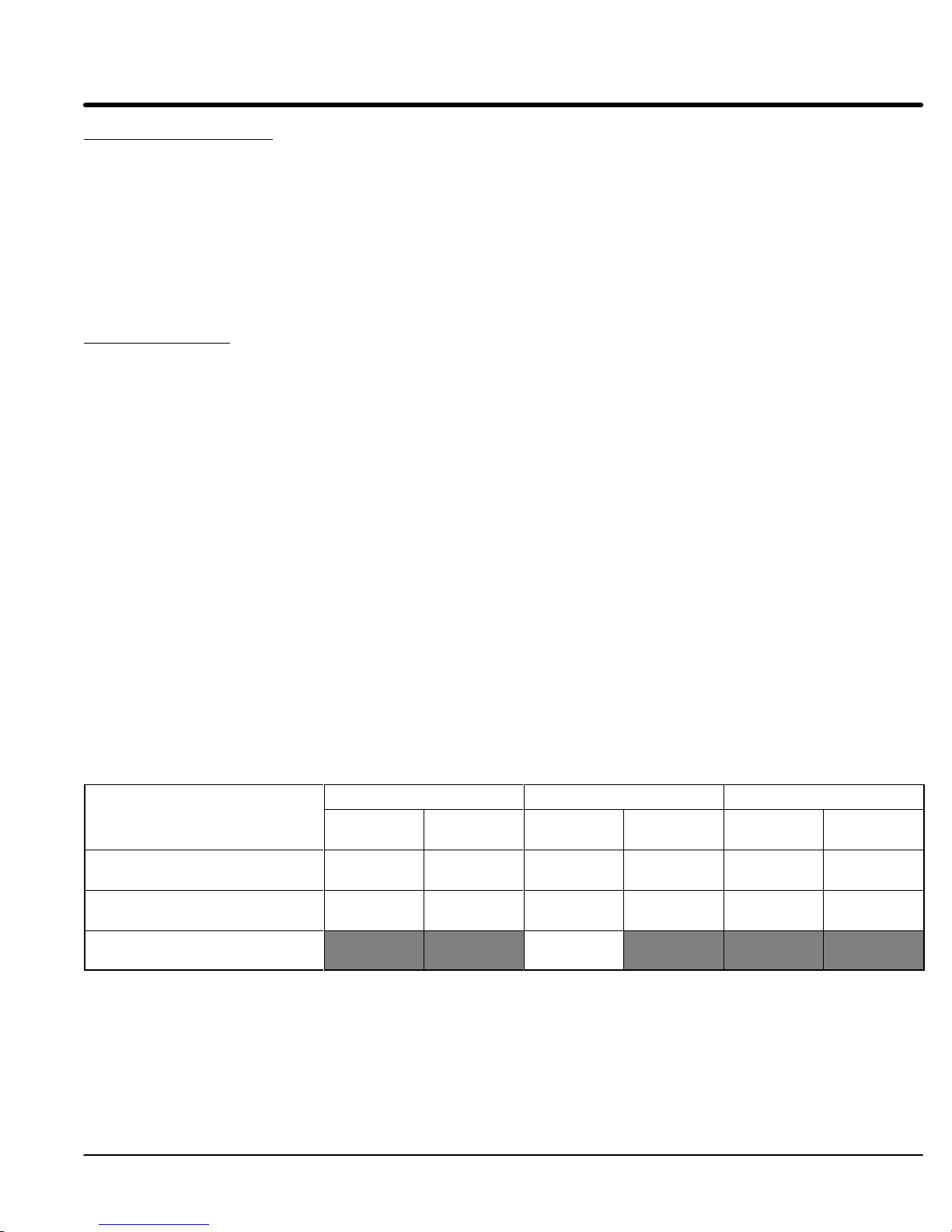
Table 3-1 Series 18H Watts Loss Ratings
Enclosure
A and B
C, D, E, and F
MN718
Size
G
2.5KHz
PWM
14 W
Amp
12 W
Amp
230 V
atts/
atts/
AC
8.0KHz
PWM
17 W
15 W
atts/
Amp
atts/
Amp
2.5KHz
PWM
17 W
Amp
15 W
Amp
15 W
Amp
460 V
atts/
atts/
atts/
AC
8.0KHz
PWM
26 W
Amp
23Watts/
Amp
atts/
2.5KHz
PWM
18 W
atts/
Amp
19Watts/
Amp
Receiving
575 V
AC
8.0KHz
PWM
28 W
atts/
Amp
29 W
atts/
Amp
& Installation 3-1

Section 1
General Information
Control Installation The
control must be securely fastened to the mounting surface. Use the four (4)
mounting holes to fasten the control to the mounting surface or enclosure.
Shock Mounting
If the control will be subjected to levels of vibration greater than 0.5G at 10 to 60Hz, the
control should be shock mounted. Excessive vibration within the control could cause
internal connections to loosen and cause component failure or electrical shock hazard.
Through the Wall MountingControl
control through the wall, a Through the W
are:
Kit No. Description
KT0000A00
KT0001A00
V0083991
V0084001
Procedure:
1.
2.
3.
4.
5.
6.
sizes E and F are designed for panel or through the wall installation. T
all mounting kit must be purchased. These kits
Size A control through the wall mounting kit.
Size B control through the wall mounting kit.
Size E control through the wall mounting kit.
Size F control through the wall mounting kit.
Refer to Section 7 of this manual for drawings and dimensions of the through
the wall mounting kits. Use the information contained in these drawings to
layout the appropriate size hole on your enclosure and wall.
Cut the holes in your enclosure and wall.
Locate and drill holes for mounting hardware as shown in the drawings.
Cut foam tape and apply to perimeter of opening as shown.
Secure the four (4) brackets to the exterior of the customers panel with the
hardware provided.
Secure the control to the customers panel using the hardware provided.
o mount a
3-2
Receiving & Installation
MN718

Section 1
General Information
Optional Remote Keypad Installation
extension cable. The keypad assembly (white - DC00005A-01; grey - DC00005A-02)
comes complete with the screws and gasket required to mount it to an enclosure. When
the keypad is properly mounted to a NEMA T
4X indoor rating.
Tools Required:
Mounting Instructions: For tapped mounting holes
Mounting Instructions:
For clearance mounting holes
The keypad may be remotely mounted using the optional Baldor keypad
•
Center punch, tap handle, screwdrivers (Phillips and straight) and crescent
wrench.
•
8-32 tap and #29 drill bit (for tapped mounting holes) or #19 drill (for clearance
mounting holes).
• 1-1/4″
• R
•
•
•
1.
2.
3.
4.
5.
6.
7.
8.
9.
1.
2.
3.
4.
5.
6.
7.
8.
9.
standard knockout punch (1-11/16″
TV sealant.
(4) 8-32 nuts and lock washers.
Extended 8-32 screws (socket fillister) are required if the mounting surface is
thicker than 12 gauge and is not tapped (clearance mounting holes).
Remote keypad mounting template. A tear out copy is provided at the end of
this manual for your convenience.
Locate a flat 4″ wide x 5.5″ minimum high mounting surface. Material should
be suf
ficient thickness (14 gauge minimum).
Place the template on the mounting surface or mark the holes as shown.
Accurately center punch the 4 mounting holes (marked A) and the large
knockout (marked B).
Drill four #29 mounting holes (A). Thread each hole using an 8-32 tap.
Locate the 1-1/4″
instructions.
Debur knockout and mounting holes making sure the panel stays clean and flat.
Apply R
Assemble the keypad to the panel. Use 8–32 screws, nuts and lock washers.
From the inside of the panel, apply R
and nuts. Cover a 3/4″
encapsulate the nut and washer
Locate a flat 4″ wide x 5.5″ minimum high mounting surface. Material should
be suf
Place the template on the mounting surface or mark the holes as shown on the
template.
Accurately center punch the 4 mounting holes (marked A) and the large
knockout (marked B).
Drill four #19 clearance holes (A).
Locate the 1-1/4″
instructions.
Debur knockout and mounting holes making sure the panel stays clean and flat.
Apply R
Assemble the keypad to the panel. Use 8–32 screws, nuts and lock washers.
From the inside of the panel, apply R
and nuts. Cover a 3/4″
encapsulate the nut and washer
TV to the 4 holes marked (A).
ficient thickness (14 gauge minimum).
TV to the 4 holes marked (A).
ype 4X indoor enclosure, it retains the T
nominal diameter).
knockout center (B) and punch using the manufacturers
TV over each of the four mounting screws
area around each screw while making sure to completely
.
knockout center (B) and punch using the manufacturers
TV over each of the four mounting screws
area around each screw while making sure to completely
.
ype
MN718
Receiving
& Installation 3-3
Section 1
General Information
Electrical Installation Interconnection
host control and any operator interface stations. Use listed closed loop connectors that
are of appropriate size for wire gauge being used. Connectors are to be installed using
crimp tool specified by the manufacturer of the connector
used.
Baldor Series H controls feature UL approved adjustable motor overload protection
suitable for motors rated at no less than 50% of the output rating of the control. Other
governing agencies such as NEC may require separate over–current protection. The
installer of this equipment is responsible for complying with the National Electric Code
and any applicable local codes which govern such practices as wiring protection,
grounding, disconnects and other current protection.
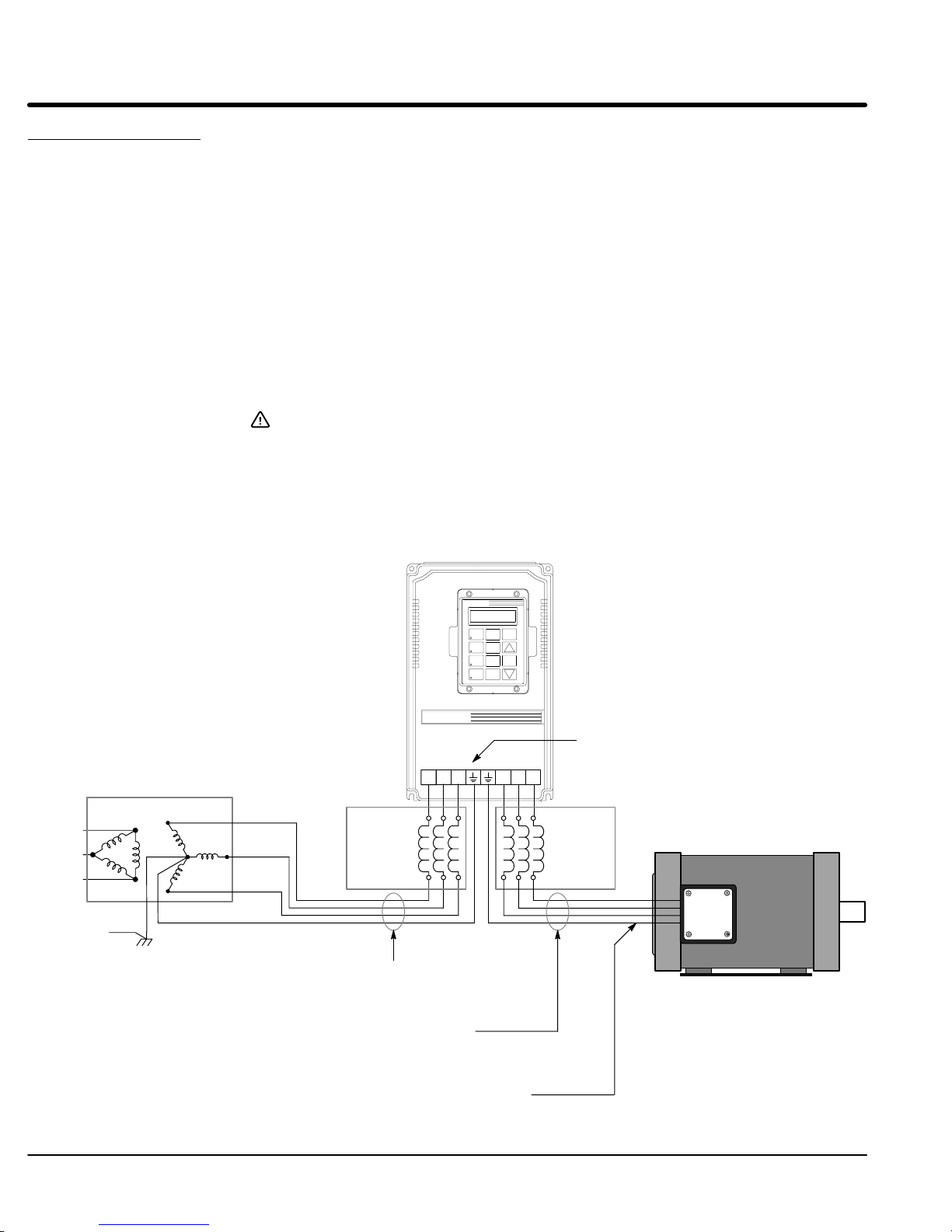
System Grounding
Baldor Controls are designed to be powered from standard three phase lines that are
electrically symmetrical with respect to ground. System grounding is an important step in
the overall installation to prevent problems. The recommended grounding method is
shown in Figure 3-1.
Caution: Baldor recommends not using “Grounded Leg Delta” transformer
Figure 3-1 Recommended System Grounding
wiring is required between the motor control, AC power source, motor
. Only Class 1 wiring should be
power leads that may create ground loops and degrade system
performance. Instead, we recommend using a four wire W
ye.
,
AC Main
Supply
Safety
Ground
Driven Earth
Ground Rod
(Plant Ground)
L1
L2
L3
Earth
Four Wire
“Wye”
Route all 4 wires L1, L2, L3 and Earth
(Ground) together in conduit or cable.
Route all 4 wires T1, T2, T3 and Motor
Ground together in conduit or cable.
Optional
Line
Reactor
LOCAL
JOG
DISP
FWD
SHIFT
REV
RESET
STOP
Series H
L1
L2 L3 T1 T2 T3
PROG
ENTER
Note: Wiring shown for clarity of grounding
method only. Not representative of
actual terminal block location.
Optional
Load
Reactor
Ground
per NEC and
Local codes.
Connect all wires (including motor ground)
inside the motor terminal box.
3-4
Receiving & Installation
MN718

Section 1
General Information
Ungrounded Distribution System
With an ungrounded power distribution system it is possible to have a continuous current
path to ground through the MOV devices. T
transformer with a grounded secondary is recommended. This provides three phase AC
power that is symmetrical with respect ground.
Input Power Conditioning
Baldor controls are designed for direct connection to standard three phase lines that are
electrically symmetrical with respect to ground. Certain power line conditions must be
avoided. An AC line reactor or an isolation transformer may be required for some power
conditions.
S
Baldor Series H controls require a minimum line impedance of 3%. Refer to
“Line Impedance” for additional information.
S
If the feeder or branch circuit that provides power to the control has
permanently connected power factor correction capacitors, an input AC line
reactor or an isolation transformer must be connected between the power factor
correction capacitors and the control.
S
If the feeder or branch circuit that provides power to the control has power
factor correction capacitors that are switched on line and of
must not be switched while the control is connected to the AC power line. If the
capacitors are switched on line while the control is still connected to the AC
power line, additional protection is required. TVSS (T
Suppressor) of the proper rating must be installed between the AC line reactor
or an isolation transformer and the AC input to the control.
o avoid equipment damage, an Isolation
f line, the capacitors
ransient V
oltage Surge
MN718
Receiving
& Installation 3-5

Section 1
General Information
Line Impedance
The Baldor Series 18H control requires a minimum line impedance of 3% (voltage drop
across the reactor is 3% when the control draws rated input current). If the incoming
power line has less than 3% impedance, a 3 phase line reactor can be used to provide
the needed impedance in most cases. Line reactors are optional and are available from
Baldor.
The input impedance of the power lines can be determined in two ways:
1.
Measure the line to line voltage at no load and at full rated load.
Use these measured values to calculate impedance as follows:
(Volts
%Impedance+
2.
Calculate the short circuit current capacity of the power line. If the short circuit
NoLoadSpeed
(Volts
*Volts
NoLoadSpeed
FullLoadSpeed
)
)
100
current capacity is greater than the published maximum short circuit current
ratings for the control, a line reactor should be installed.
T
wo methods of calculating short circuit current capacity are provided:
A.
Method 1
Calculate short circuit current as follows:
SC
+
(KVA
I
Example: 50KV
SC
(50 1000 100)
+
B.
I
Method 2
Step 1: Calculate KV
KVA
SC
+
(%Z
A transformer with 2.75% impedance @ 460V
(2.75 460 3Ǹ)
1000 100)
XFMR
V
XFMR
A short circuit as follows:
(KVA
XFMR
%Z
XFMR
(
)
100
3Ǹ)
L*L
AC
+2282Amps
)
+
50
ǒ
.0275
Ǔ
+1818.2KVA
Step 2: Calculate short circuit current as follows:
SC
(KVASC 1000)
+
(V
L*L
3Ǹ)
I
1818.2 1000
+
460 3
+2282Amps
Ǹ
where:
KVA
XFMR
=T
ransformer KV
A
Isc=short circuit current
Z
=T
XFMR
V
L–L
ransformer Impedance
=Input volts measured line to line
3-6
Receiving & Installation
MN718

Section 1
General Information
Line Reactors
Load
Reactors
Three phase line reactors are available from Baldor
the *Quad Rated HP of the control. If providing your own line reactor
formula to calculate the minimum inductance required. T
. The line reactor to order is based on
, use the following
able 3-3 lists the input current
required for this calculation, for each control size.
(V
0.03)
L
LL
(I 3 377)
Where:
L Minimum inductance in Henries.
V
L–L
0.03 Desired percentage of input impedance.
I Input current rating of control.
377 Constant used with 60Hz power.
Line reactors may be used at the control output to the motor
Input volts measured line to line.
Use 314 if input power is 50Hz.
. When used this way
, they
are called Load Reactors. Load reactors serve several functions that include:
S
Protect the control from a short circuit at the motor
S
Limit the rate of rise of motor surge currents.
S
Slowing the rate of change of power the control delivers to the motor
.
.
Load reactors should be installed as close to the control as possible. Selection should be
based on the motor nameplate FLA value.
*Quad Rated HP of the control refers to the four (4) dif
ferent HP ratings of the control that
are based on operating in Standard (2.5KHz PWM) or Quiet (8.0KHz PWM) in either
Constant T
orque or V
ariable T
orque. The ratings are provided in Section 7 of this
manual.
MN718
Receiving
& Installation 3-7

Section 1
General Information
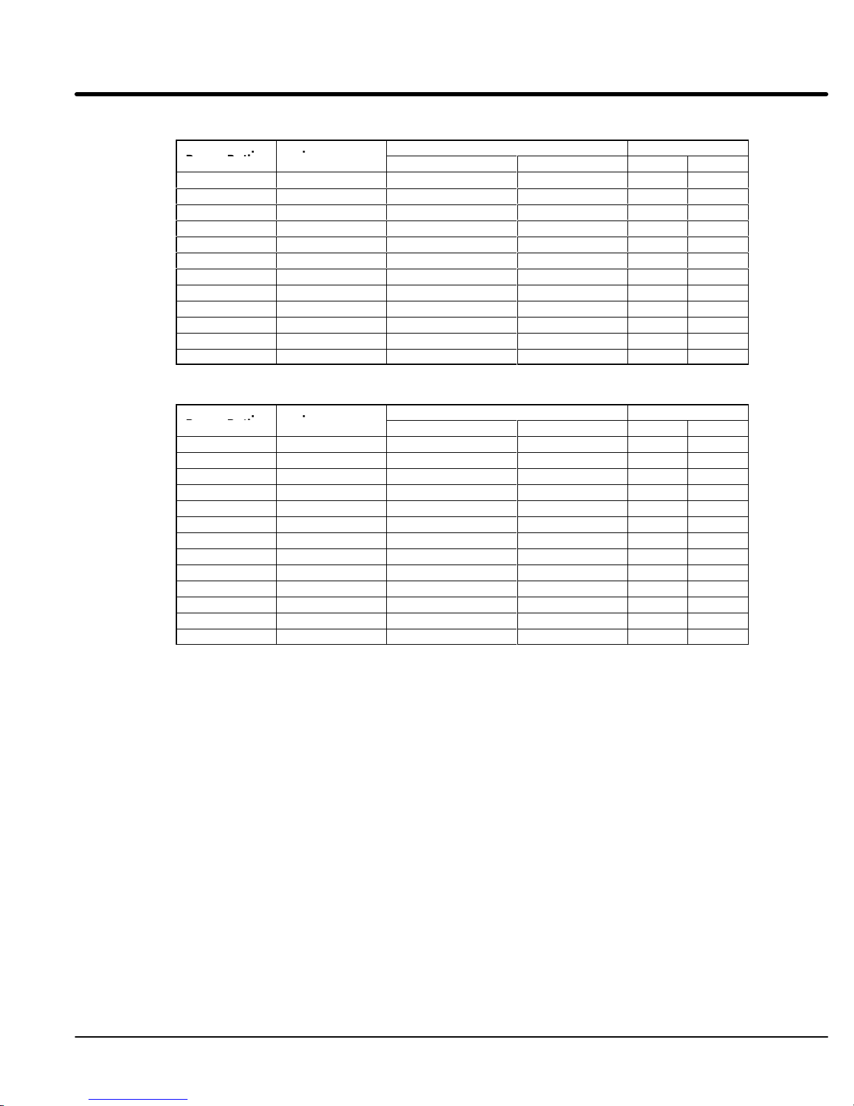
Table 3-2 Short Circuit Current Ratings
230VAC 460VAC 575VAC
Catalog Numbers Max. Line
Short Circuit
Amps
ZD18H201–E 250 ZD18H401–E 150 ZD18H501–E 50
ZD18H201–W 350 ZD18H401–W 200 ZD18H502–E 100
ZD18H202–E 350 ZD18H402–E 200 ZD18H503–E 150
ZD18H202–W 550 ZD18H402–W 300 ZD18H505–E 200
ZD18H203–E or W 550 ZD18H403–E or W 300 ZD18H507–E 300
ZD18H205–E 550 ZD18H405–E 300 ZD18H510–E 400
ZD18H205–W 1000 ZD18H405–W 500 ZD18H515–E, EO or ER 600
ZD18H207–E or W 1000 ZD18H407–E or W 500 ZD18H520–EO or ER 1000
ZD18H210–E 1000 ZD18H410–E 500 ZD18H525–EO or ER 1100
ZD18H210L–ER 1500 ZD18H410L–ER 800 ZD18H530–EO or ER 1500
ZD18H215–E, EO or ER 1900 ZD18H415–E, EO or ER 1000 ZD18H540–EO or ER 1800
ZD18H215L–ER 1900 ZD18H415L–ER 1000 ZD18H550–EO or ER 2200
ZD18H220–EO or ER 2400 ZD18H420–EO or ER 1200 ZD18H560–EO or ER 2700
ZD18H220L–ER 2100 ZD18H420L–ER 1200 ZD18H575–EO or ER 3300
ZD18H225–EO or ER 2800 ZD18H425–EO or ER 1400 ZD18H5100–EO or ER 4200
ZD18H225L–ER 2500 ZD18H425L–ER 1400 ZD18H5150V–EO or ER 4800
ZD18H230V–EO or ER 3600 ZD18H430V–EO or ER 1800
ZD18H230–EO or ER 3600 ZD18H430–EO or ER 1800
ZD18H230L–ER 3600 ZD18H430L–ER 1800
ZD18H240–MO or MR 4500 ZD18H440–MO or MR 2300
ZD18H240L–MR 4000 ZD18H440L–MR 2300
ZD18H250V–MO or MR 4500 ZD18H450–EO or ER 2800
ZD18H250–MO or MR 4500 ZD18H450L–ER 2800
Catalog Numbers Max. Line
Short Circuit
Amps
ZD18H460–EO or ER 3500
ZD18H460V–EO or ER 3500
ZD18H460L–ER 3500
ZD18H475–EO 4300
ZD18H475L–EO 4300
ZD18H4100–EO 5500
ZD18H4150V–EO 6200
ZD18H4150–EO 8300
ZD18H4200–EO 11000
ZD18H4250–EO 13800
ZD18H4300–EO 16600
ZD18H4350–EO 19900
ZD18H4400–EO 19900
ZD18H4450–EO 25000
Catalog Numbers Max. Line
Short Circuit
Amps
3-8
Receiving & Installation
MN718

Section 1
230 VAC Control
Input
460 VAC Control
Input
575 VAC Control
Input
General Information
Input Current Requirements
Table 3-3 Input Current Requirements
230 VAC Control Input 460 VAC Control Input 575 VAC Control Input
Catalog Numbers
ZD18H201-E or W 6.8 ZD18H401-E or W 3.4 ZD18H501-E 2.7
ZD18H202-E or W 9.6 ZD18H402-E or W 4.8 ZD18H502-E 4.0
ZD18H203-E or W 15.2 ZD18H403-E or W 7.6 ZD18H503-E 6.1
ZD18H205-E 15.2 ZD18H405-E or W 11 ZD18H505-E 11
ZD18H205-W 22 ZD18H407-E 11 ZD18H507-E 11
ZD18H207-E or W 28 ZD18H407-W 14 ZD18H510-E 11
ZD18H210-E 28 ZD18H410-E 21 ZD18H515-EO or ER 22
ZD18H210L-ER 42 ZD18H410L-ER 21 ZD18H520-EO or ER 27
ZD18H215-E 42 ZD18H415-E 21 ZD18H525-EO or ER 32
ZD18H215-EO or ER 54 ZD18H415-EO or ER 27 ZD18H530-EO or ER 41
ZD18H220-EO or ER 68 ZD18H415L-ER 27 ZD18H540-EO or ER 52
ZD18H220L-ER 60 ZD18H420-E or ER 34 ZD18H550-EO or ER 62
ZD18H225-EO or ER 80 ZD18H420L-ER 30 ZD18H560-EO or ER 62
ZD18H225L-ER 75 ZD18H425-EO or ER 40 ZD18H575-EO 100
ZD18H230-EO or ER 104 ZD18H425L-ER 38 ZD18H5100-EO 125
ZD18H230V-EO or ER 104 ZD18H430-EO or ER 52 ZD18H5150V-EO 145
ZD18H230L-ER 104 ZD18H430L-ER 52
ZD18H240-MO or MR 130 ZD18H430V-EO or ER 52
ZD18H240L-MR 115 ZD18H430L-ER 52
ZD18H250-MO or MR 130 ZD18H440-EO or ER 65
ZD18H250V-MR 130 ZD18H440L-ER 60
Amps
Catalog Numbers
ZD18H450-EO or ER 80
ZD18H450L-ER 80
ZD18H460-EO or ER 100
ZD18H460V-EO or ER 100
ZD18H460L-ER 100
ZD18H475-EO 125
ZD18H475L-EO 125
ZD18H4100-EO 160
ZD18H4150-EO 240
ZD18H4150V-EO 180
ZD18H4200-EO 310
ZD18H4250-EO 370
ZD18H4300-EO 420
ZD18H4350-EO 480
ZD18H4400-EO 540
ZD18H4450-EO 590
Amps
Catalog Numbers
Amps
MN718
Receiving
& Installation 3-9

Section 1
Control Output
I
I
Wi
p
p
General Information
AC Main Circuit
Protection Devices Be
Power Disconnect A
Wire Size and Protection Devices
Table 3-4 Wire Size and Protection Devices - 230 VAC Controls
sure a suitable input power protection device is installed. Use the recommended circuit
breaker or fuses listed in Tables 3-4 through 3-6 (Wire Size and Protection Devices). Wire
sizes
rating
power from the control will be less than the maximum, the sizes of the wire and protective
devices
Input
and output wire size is based on
table
is specified for NEMA B motors.
Circuit Breaker: 1 phase, thermal magnetic.
Fast Action Fuses: 230 VAC, Buss KTN
Very Fast Action: 230 VAC, Buss JJN
Time Delay Fuses: 230 VAC, Buss FRN
power
a
fail safe method to disconnect power
all
input power is removed from the control and the internal bus voltage is depleted.
and protective device specifications are based on the controls’ maximum output power
for the operating zone. Refer to Quad ratings in Section 7 of this manual.
may be adjusted accordingly
. Be sure to follow NEC, UL and other applicable codes.
If the output
the use of copper conductor wire rated at 75 °C. The
Equal to GE type THQ or TEB for 230 VAC
3 phase, thermal magnetic.
Equal to GE type THQ or TEB for 230 VAC or
GE type TED for 460 VAC and 575 VAC.
460 VAC, Buss KTS to 600A (KTU 601 - 1200A)
575VAC, Buss FRS
460 VAC, Buss JJS
575 VAC, , Buss JJS
460 VAC, Buss FRS to 600A (KTU 601 - 1200A)
575 VAC, Buss FRS to 600A (KTU 601 - 1200A)
disconnect should be installed between the input power service and the control for
. The control will remain in a powered-up condition until
Note: All
Power Rating
1 5A 5A 5A 14 2.5
2 10A 10A 8A 14 2.5
3 15A 15A 12A 14 2.5
5 20A 25A 12.5A 14 2.5
7.5 25A 30A 25A 12 4
10 35A 40A 35A 10 10
15 50A 60A 50A 8 10
20 60A 80A 60A 4 25
25 80A 100A 80A 4 25
30 100A 125A 100A 3 30
40 125A 150A 125A 1 50
50 150A 200A 150A 2/0 70
nput Breaker
Fast Acting Time Delay AWG mm
wire sizes based on 75°C copper wire, 3% line impedance. Higher temperature smaller gauge wire may be
nput Fuse
re Gauge
used per NEC and local codes. Recommended fuses/breakers are based on 25°C ambient, maximum
continuous control output current and no harmonic current.
2
3-10
Receiving & Installation
MN718

Section 1
Control Output
I
I
Wi
p
p
General Information
Table 3-5 Wire Size and Protection Devices - 460 VAC Controls
Power Rating
1 4A 4A 3A 14 2.5
2 10A 5A 4A 14 2.5
3 10A 8A 6A 14 2.5
5 10A 12A 9A 14 2.5
7.5 15A 20A 15A 14 2.5
10 20A 25A 17.5A 12 4
15 25A 30A 25A 10 6
20 30A 40A 30A 8 10
25 40A 50A 40A 8 10
30 45A 60A 45A 6 16
40 60A 80A 60A 4 25
50 70A 100A 75A 4 25
60 90A 125A 90A 2 35
75 125A 150A 125A 1/0 54
100 150A 200A 150A 2/0 70
125 175A 250A 175A 2/0 70
150 200A 300A 200A 4/0 120
200 250A 350A 250A (2)1/0 (2)54
250 350A 450A 350A (2)3/0 (2)95
300 400A 500A 400A (2)4/0 (2)120
350 500A 600A 500A (3)4/0 (3)120
400 600A 800A 600A (3)250 mcm (3)125
450 600A 800A 600A (3)250 mcm (3)125
500 800A 1000A 800A (3)350 mcm (3)185
nput
Breaker
Fast Acting Time Delay AWG mm
nput Fuse
re Gauge
2
Note: All
wire sizes based on 75°C copper wire, 3% line impedance. Higher temperature smaller gauge wire may be
used per NEC and local codes. Recommended fuses/breakers are based on 25°C ambient, maximum
continuous control output current and no harmonic current.
Receiving
& Installation 3-1
1MN718

Section 1
Control Output
I
I
Wi
p
p
General Information
Table 3-6 Wire Size and Protection Devices - 575 VAC Controls
Note: All
Power Rating
1 5A 5A 4A 14 2.5
2 10A 5A 4A 14 2.5
3 10A 6A 5A 14 2.5
5 10A 10A 7A 14 2.5
7.5 10A 15A 10A 14 2.5
10 15A 15A 12A 14 2.5
15 20A 25A 20A 12 4
20 25A 35A 25A 10 6
25 30A 40A 30A 8 10
30 35A 50A 35A 8 10
40 45A 60A 45A 6 16
50 60A 80A 60A 4 25
60 70A 90A 70A 4 25
75 120A 150A 120A 3 27
100 120A 150A 120A 1/0 54
125 150A 200A 150A 2/0 70
150 175A 225A 175A 2/0 70
nput
Breaker
Fast Acting Time Delay AWG mm
wire sizes based on 75°C copper wire, 3% line impedance. Higher temperature smaller gauge wire may be
nput Fuse
re Gauge
used per NEC and local codes. Recommended fuses/breakers are based on 25°C ambient, maximum
continuous control output current and no harmonic current.
2
3-12
Receiving & Installation
MN718

Section 1
General Information
AC Line Connections Be
applied to the control, wait at least 5 minutes after power disconnect for residual voltage
across bus capacitors to discharge.
Reduced Input Voltage Derating
All
460 or 575V
reduced input voltage. The amount of reduction is the ratio of the voltage change.
Examples:
For example, a 10HP
of 9.04HP
10HP
Likewise, a 10HP
8.26HP
10HP
T
380-400 VAC Configuration
control modification is not necessary
Size C, D, E, F and G controls all require modification for operation on the reduced line
voltage (380-400V
T
sure all power to the control is disconnected before proceeding. If power has been
power ratings stated in Section 7 are for the stated nominal AC input voltages (230,
AC). The power rating of the control must be reduced when operating at a
, 230V
AC control operating at 208V
.
208VAC
230VAC
.
380VAC
460VAC
o obtain the full output rating of 10HP in either case requires a 15HP Control.
Size A and B controls may be used directly with a 380-400 V
ap Change Procedure
1.
Be sure drive operation is terminated and control is disabled.
2.
Remove all power sources from the control. If power has been applied, wait at
least 5 minutes for bus capacitors to discharge.
3.
Remove or open the front cover
4.
Remove the wire from terminal 5.
5.
Place the wire that was removed from terminal 5 onto terminal 4.
6.
Install or close the front cover
9.04HP
, 460V
AC control operating at 380V
8.26HP
.
AC).
(size C, D, E and F controls).
.
.
AC has a reduced power rating
AC has a reduced power rating of
AC power source,
MN718
Receiving
& Installation 3-13
Section 1
General Information
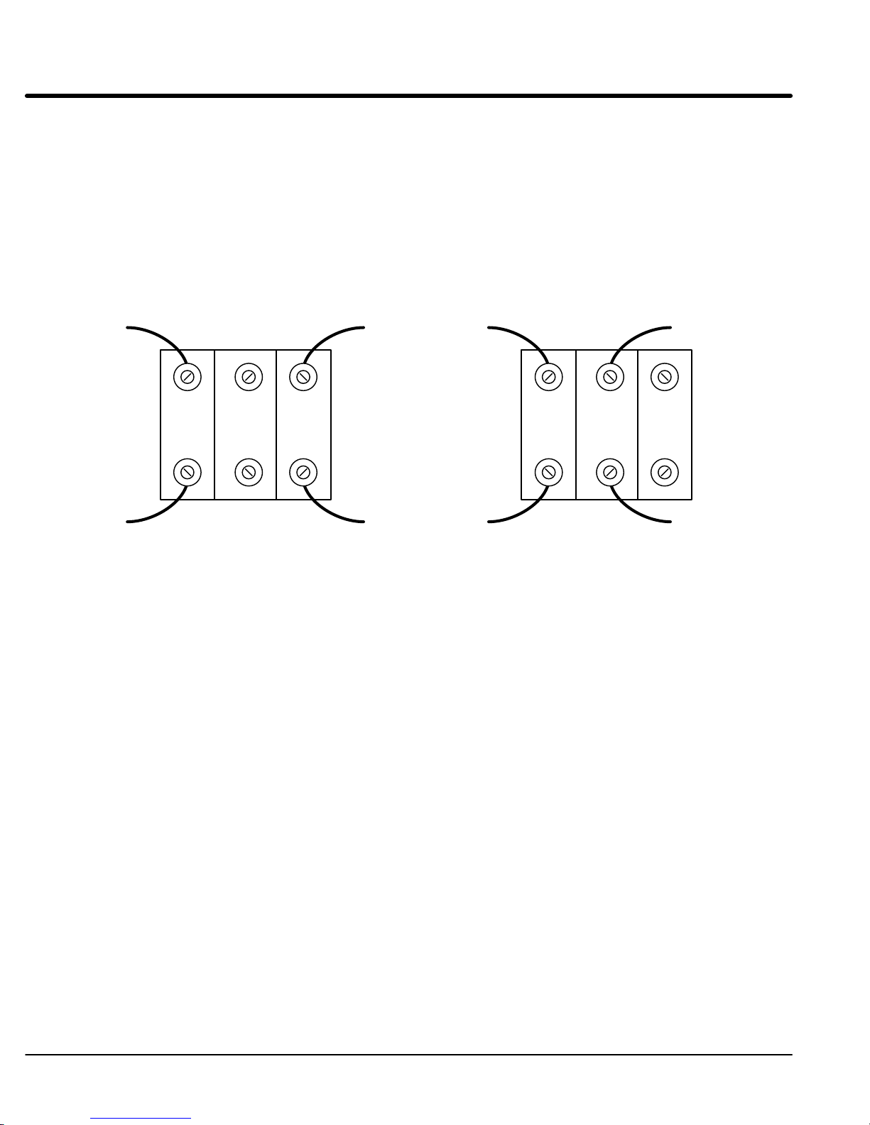
Figure 3-2 Configuring the Control Transformer Terminal Block for 380 - 400 VAC (Size G)
T
ap Change Procedure
1.
Be sure drive operation is terminated and control is disabled.
2.
Remove all power sources from the control. If power has been applied, wait at
least 5 minutes for bus capacitors to discharge.
3.
Remove or open the front cover
4.
Remove the wires from the two right side terminals.
5.
Place the wires on the center terminals as shown.
6.
Install or close the front cover
(size G controls). See Figure 3-2.
.
.
460VAC 380-400VAC
3-14
Receiving & Installation
MN718

Section 1
General Information
Three Phase Input Power
Three
phase AC power and motor connections are shown in Figure 3-3. Overloads are
not required. The 18H control has an electronic I2t motor overload protection. If motor
overloads are desired, they should be sized according to the manufacturers specifications
and installed between the motor and the T1, T2 and T3 terminals of the control.
Caution: Do not connect AC power to the Motor terminals T1, T2 and T3.
Connecting AC power to these terminals may result in damage to
the control.
Caution: Baldor recommends not using “Grounded Leg Delta” transformer
power leads that may create ground loops and degrade system
performance. Instead, we recommend using a four wire W
1.
Connect the incoming AC power wires from the protection devices to L1, L2
and L3 at the Main Circuit T
control is not phase sensitive.
2.
* Connect earth ground to the “ ” of the control. Be sure to comply with local
codes.
Note:
Use same gauge wire for earth ground as is used for L1, L2 and L3
connections. Refer to the Wire Size and Protection Devices tables
shown previously in this section.
erminals. The phase rotation is not important as the
ye.
3.
Connect the three phase power leads of the AC motor to terminals T1, T2, and
T3 of the Main Circuit T
4.
* Connect motor ground wire to the “
all applicable codes.
*
Grounding by using conduit or panel connection is not adequate. A separate
conductor of the proper size must be used as a ground conductor
erminals.
” of the control. Be sure to comply with
.
MN718
Receiving
& Installation 3-15
Section 1
General Information
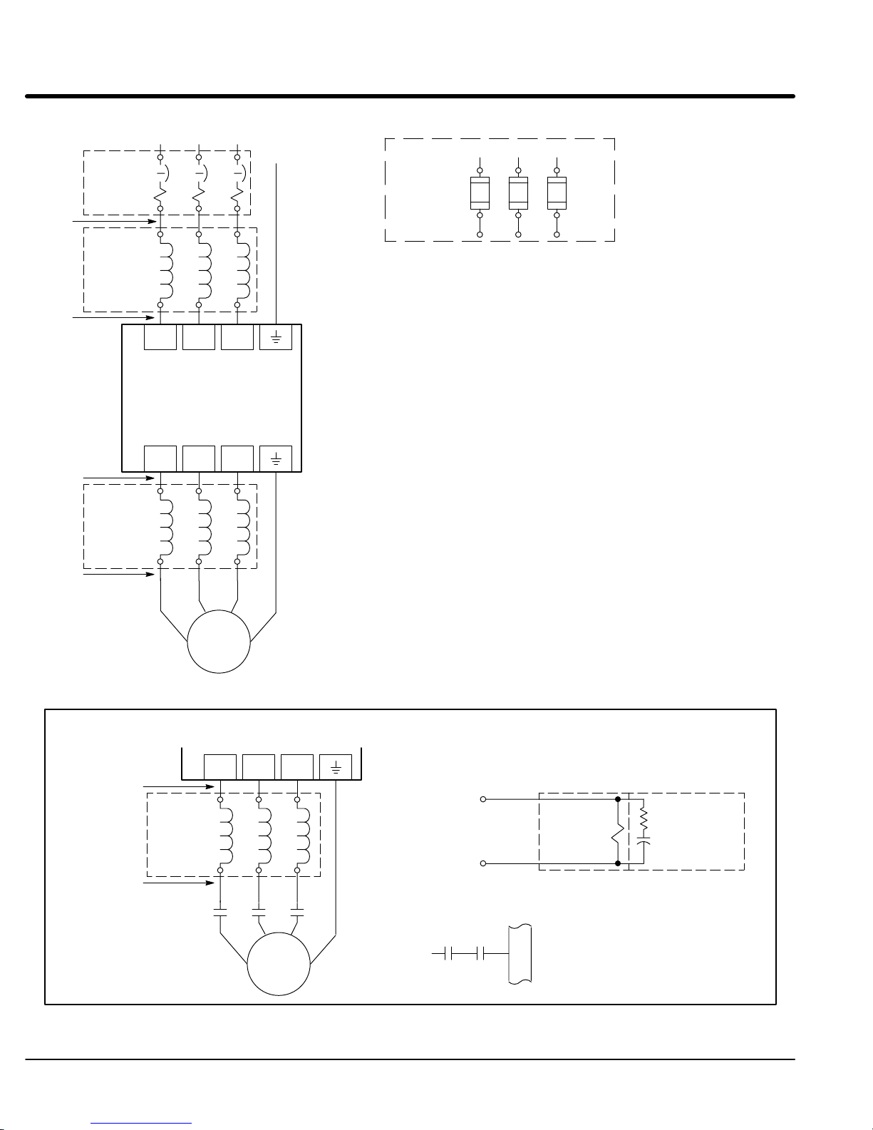
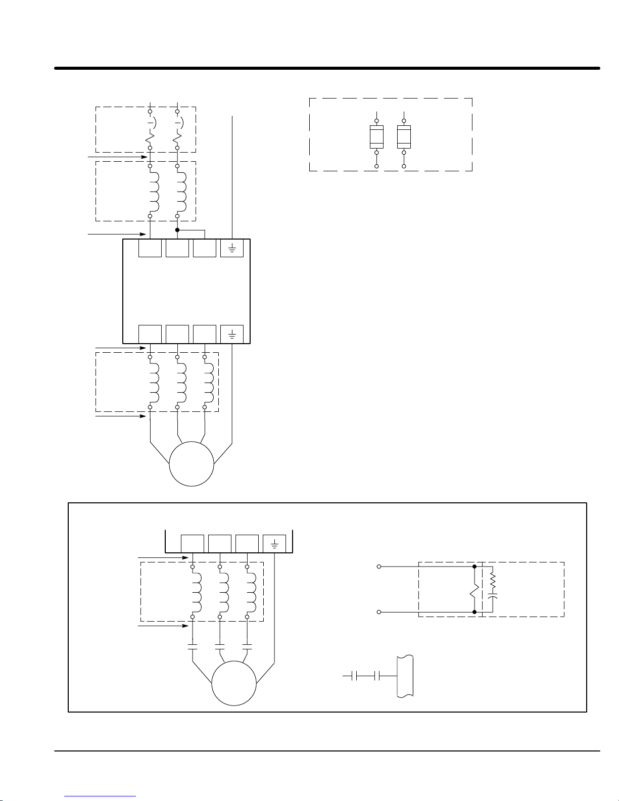
Figure 3-3 Three Phase AC Power and Motor Connections
L1 L2 L3
Note 1
Note 2
* Circuit
Breaker
A1 B1 C1
Earth
Alternate *
Fuse
Connection
L1 L2 L3
Note 1
A1 B1 C1
Note 4
Note 2
Note 3
Note 4
Note 3
*Optional
Line
Reactor
*Optional
Load
Reactor
A2 B2 C2
L1 L2 L3
Baldor
Series
Control
T1 T2 T3
A1 B1 C1
A2 B2 C2
T2 T3
T1
18H
G
* Optional components not provided with 18H Control.
Notes:
1. See
2.
3.
4.
5.
“Protective Devices” described previously in this section.
Shield wires inside a metal conduit.
Metal conduit should be used to shield output wires (between
control and motor). Connect conduits so the use of Load Reactor
or RC Device does not interrupt EMI/RFI shielding.
See Line/Load Reactors described later in this section.
A motor circuit contactor is recommended to provide a positive
disconnect and prevent motor rotation which could pose a safety
hazard. Connect the M-Contactor as shown. The contactor
should open the enable input at J1-8 at least 20 msec before the
main M-contacts open to prevent arcing at contacts. This greatly
increases contactor life and allows use of IEC rated contactors.
Note 3
*Optional
Note 4
Load
Reactor
Note 3
M=Contacts of optional M-Contactor
3-16
Receiving & Installation
* AC Motor
T1 T2 T3
A1 B1 C1
A2 B2 C2
MMM
T2 T3
T1
* Motor
See Recommended Tightening Torques in Section 7.
Optional Connection of
Load Reactor and M-Contactor
G
To Power Source
(Rated Coil
Voltage)
J1
*
M Enable
7
8
9
Note 5
* M-Contactor
Note: Close “Enable”
after “M” contact closure.
* Optional
RC Device
Electrocube
RG1781-3
MN718
Section 1
p
p
p
p
General Information
Table 3-7 Single Phase Rating Wire Size and Protection Devices - 230 VAC Controls
Control Output
Power Rating
1 15A 5A 5A 14 2.5
2 15A 10A 10A 14 2.5
3 15A 15A 15A 14 2.5
5 30A 30A 30A 12 4
7.5 25A 25A 25A 14 2.5
10 40A 30A 30A 12 4
15 50A 45A 45A 10 6
20 60A 45A 45A 8 10
25 70A 70A 70A 8 10
30 80A 80A 80A 6 16
40 100A 100A 100A 4 25
50 125A 125A 125A 4 25
Input Breaker Input Fuse Wire Gauge
Fast Acting Time Delay AWG mm
2
Table 3-8 Single Phase Rating Wire Size and Protection Devices - 460 VAC Controls
Control Output
Power Rating
1 15A 4A 4A 14 2.5
2 15A 8A 8A 14 2.5
3 15A 10A 10A 14 2.5
5 15A 15A 15A 14 2.5
7.5 15A 15A 15A 14 2.5
10 20A 15A 15A 14 2.5
15 25A 25A 25A 14 2.5
20 30A 30A 30A 14 2.5
25 35A 30A 30A 14 2.5
30 40A 40A 40A 10 6
40 60A 50A 50A 8 10
50 70A 60A 60A 8 10
60 80A 80A 80A 6 16
Input Breaker Input Fuse Wire Gauge
Fast Acting Time Delay AWG mm
2
Note: All
wire sizes based on 75°C copper wire, 3% line impedance. Higher temperature smaller gauge wire may be
used per NEC and local codes. Recommended fuses/breakers are based on 25°C ambient, maximum
continuous control output current and no harmonic current.
MN718
Receiving
& Installation 3-17

Single
Phase Input Power Considerations
Caution: Do not connect AC power to the Motor terminals T1, T2 and T3.
Connecting AC power to these terminals may result in damage to
the control.
Caution: Baldor recommends not using “Grounded Leg Delta” transformer
power leads that may create ground loops and degrade system
performance. Instead, we recommend using a four wire W
Single phase AC input power can be used to power the control instead of three phase for
control sizes A, B, C, D, E and F
. Single phase operation of G size controls is not
possible. The specifications and control sizes are listed in Section 7 of this manual. If
single phase power is to be used, the rated Horsepower of the control may have to be
reduced (derated). In addition, power wiring and jumper changes are required.
Single phase rating wire size and protection devices are listed in T
ables 3-7 and 3-8.
Single Phase Control Derating: Single phase power derating requires that the continuous and peak current ratings
of the control be reduced by the following percentages:
1.
1-2 HP 230 and 460 V
AC controls:
No derating required.
2.
3-15 HP (Size B) 230 and 460 V
AC controls:
Derate HP by 40% of the nameplate rating.
3.
15 HP (Size C) and Larger 230 and 460 V
AC controls:
Derate HP by 50% of the nameplate rating.
ye.
Size A and B Single Phase Power Installation
Jumper Configuration
Size A and B controls, no jumper changes required.
Power and Control Connections
The
single phase power and motor connections are shown in Figure 3-4.
1.
Connect the incoming power wires to Main Circuit T
2.
Place a jumper across control power input terminals L2 and L3. Use the same
size wire for the jumper as the incoming power wires on L1 and L2.
3.
Connect earth ground to the “
codes.
Note:
Use same gauge wire for earth ground as is used for L1, L2 and L3
connections. Refer to the Wire Size and Protection Devices tables
shown previously in this section.
4.
Connect the three phase power leads of the AC motor to terminals T1, T2, and
T3 of the Main Circuit T
5.
Connect motor ground wire to the “
applicable codes.
Note:
In steps 3 and 5 grounding by using conduit or panel connection is not
adequate. A separate conductor of the proper size must be used as a ground
conductor.
erminals L1 and L2.
” of the control. Be sure to comply with local
erminals.
” of the control. Be sure to comply with all
3-18 Receiving & Installation
MN718
Section 1
General Information
Figure 3-4 Size A & B Single Phase 230/460VAC Power and Motor Connections
Note 1
* Circuit
Breaker
L1 L2
Earth
* Fuse
Connection
L1 L2
Note 1
Note 2
Note 4
Note 2
Note 3
Note 5
Note 3
*Optional
Line
Reactor
*Optional
Load
Reactor
A1 B1
A2 B2
L1 L2 L3
Baldor
Series
Control
T1 T2 T3
A1 B1 C1
A2 B2 C2
T2 T3
T1
18H
G
A1 B1
* Optional
components not provided with 18H Control.
Notes:
1. See
2.
3.
“Protective Devices” described previously in this section.
Shield wires inside a metal conduit.
Metal conduit should be used to shield output wires (between
control and motor).
4.
See “Line Impedance” described previously in this section.
5.
See Line/Load Reactors described previously in this section.
6.
A motor circuit contactor is recommended to provide a positive
disconnect and prevent motor rotation which could pose a safety
hazard. Connect the M-Contactor as shown. The contactor
should open the enable input at J1-8 at least 20 msec before the
main M-contacts open to prevent arcing at contacts. This greatly
increases contactor life and allows use of IEC rated contactors.
Note 3
Note 5
Note 3
M=Contacts of optional M-Contactor
*Optional
Load
Reactor
Note 6
MN718
* AC Motor
T1 T2 T3
A1 B1 C1
A2 B2 C2
MMM
T2 T3
T1
* Motor
See
Recommended T
Optional Connection of
Load Reactor and M-Contactor
To Power Source
Note 6
G
ightening T
M Enable
orques in Section 7.
(Rated Coil
Voltage)
*
Note 6
* M-Contactor
J1
7
8
9
* Optional
RC Device
Electrocube
RG1781-3
Note: Close “Enable”
after “M” contact closure.
Receiving & Installation 3-19
 Loading...