


BSC Series 2000/ 3000
Servo Control
Installation & Operating Manual
7/92

C O N T E N T S
1.0 |
Specifications ............................... |
1 |
1.1 |
Usage Definitions ....................... |
1 |
1.2 |
Identification .............................. |
1 |
1.3 |
Features ..................................... |
1 |
1.4 |
Declaration of Conformity .......... |
2 |
1.5 |
EMC Conformity and CE Marking |
2 |
1.5.1 |
EMC Installation Instructions ..... |
2 |
1.5.2 |
Specifications add components .. |
3 |
1.5.2.1 |
Mains Filters .............................. |
3 |
1.5.2.2 |
Connection Cables ..................... |
4 |
1.5.2.3 |
Screen Connections .................... |
4 |
1.5.2.4 |
Connectors ................................ |
4 |
1.5.2.5 |
PG-Cable Glands ....................... |
5 |
1.6 |
Technical Data ........................... |
5 |
1.6.1 |
Power Section ............................ |
5 |
1.6.2 |
24VDC Input ............................. |
6 |
1.6.3 |
Velocity Controller .................... |
6 |
1.6.4 |
Mechanical Section .................... |
6 |
1.6.5 |
Environmental Section ............... |
7 |
2.0 |
Installation Recommendations .... |
7 |
2.1 |
Mechanical Installation ............... |
7 |
2.2 |
Electrical Installation .................. |
8 |
3.0 |
Interconnection Diagram ............. |
9 |
4.0 |
BSC Wiring .............................. |
10 |
4.1 |
Power Wiring ............................. |
10 |
4.1.1 |
Power Supply ............................. |
10 |
4.1.2 |
24VDC Connection .................... |
10 |
4.1.3 |
Motor Wiring ............................. |
10 |
4.2 |
Controland Signal Wiring ......... |
11 |
4.2.1 |
Control Inputs ............................ |
11 |
4.2.2 |
Control Outputs ......................... |
12 |
4.2.3 |
Command Input ......................... |
13 |
4.2.4 |
Encoder Output ......................... |
13 |
4.2.5 |
Resolver ..................................... |
13 |
4.3 |
Minimum Wiring Diagram .......... |
14 |
5.0 |
Dimensions ................................... |
16 |
6.0 |
System Set Up Procedure ............ |
18 |
6.1 |
Presets ....................................... |
18 |
6.1.1 |
Potentiometer Preset .................. |
18 |
6.1.2 |
DIP-Switches Settings ................ |
18 |
6.2 |
System Set Up Step by Step ....... |
19 |
6.3 |
System Tuning ........................... |
20 |
7.0 |
Status Monitor ............................. |
22 |
8.0 |
Testsignals .................................... |
23 |
9.0 |
Identity Modul ............................. |
23 |
9.1 |
Component Functions ................ |
23 |
9.2 |
Component Layout .................... |
24 |
10.0 |
I/O Hardware Description ........... |
24 |
10.1 |
Input Signals .............................. |
25 |
10.2 |
Output Signals ........................... |
26 |
10.3 |
Encoder Output ......................... |
27 |
10.3.1 |
Encoder Signals ......................... |
27 |
10.4 |
Resolver ..................................... |
28 |

1
1.0Specification
1.1Usage Definitions
The amplifiers of the series BSC2000/3000 are electrical equipment for industrial power installations. They are designed for machine applications, which need variable speed controlled three-phase A.C. motors.
This product is only for use in industrial applications as described in norms EN 60204 and VDE 0160. This means use BSC2000/3000 in stationary groundbased applications only. It is not meant for use in home appliances, medical technics, cars, ships or airplanes.
Before the BSC is put into operation, please contact your Electric-Supply-Company for special operating conditions.
1.2 Identification
BSC x x xx - xx
{24 - External 24VDC-Input MR - Multiresolvercard
{ |
45 |
|
15 |
25 |
Nominal Current (Amps) |
|
35 |
||
|
{20 : Series 2000
30 : Series 3000
BALDOR-SERVO-CONTROL
1.3 Features
A BSC is an analog 1 axis amplifier with integrated power stage.
It provides the following features:
POWER SECTION: |
• Output power up to 30kVA |
|
• 3 respectively 4 output current versions (15/25/35/45A) |
|
|
available. |
• Brushless-servomotors (2 to 8 poles) can be connected. |
|
• Ratio peak : nominal current = 2:1. |
(Feedback: 2-pole resolver) |
|
Both values independently adjustable. |
• Power wiring via terminal screws (max. wiring diameter |
|
• All BSC amplifiers are short circuit proof and require |
10mm²/AWG7) |
|
no minimum load. |
|
|
CONTROL I/O Section: |
• Wiring of control inputs and outputs via plug type |
|
• 5 opto isolated control inputs for dedicated amplifier |
|
|
functions |
screw connection (max. wiring diameter 1,5mm²/ |
|
• Diagnostic display on front panel |
AWG15) or SUB-D connector |
|
GENERAL: |
• Isolation classification according to DIN 0110 with |
|
• Protection class IP20 (acc. to DIN40 050 / IEC144) |
overvoltage category II |
|
• Cooling: self-ventilation |
• Contamination level 2 |
|

2
1.4 Declaration of Conformity
Herewith we declare, that our products are components only and not ready for immediate or instant use within the meaning of "Safety law of appliance", "EMC Law" or "Machine directive".
The final mode of operation is defined only by the insertion into the user´s construction.
It is the responsibility of the user to verify that his construction is in accordance with existing regulations.
It is prohibited by law to put the machine into operation before verifying that the machine is in accordance with EC directive 89/392 and 921/368.
The supplier declares product conformity with the following standards:
DIN VDE 0160 |
/ 05.88 |
|
Electronic equipment for use in electrical power installations |
DIN VDE 0100 |
|
|
Erection of power installations with nominal voltages up to 1000V |
DIN IEC 326 Part 1 / 10.90 |
Design and use of printed boards |
||
DIN VDE 0110 |
Part 1-2 / 01.89 Dimensioning of clearance and creepage distances |
||
DIN VDE 0110 Part 20 / 08.90 |
|
||
EN 60529 / 10.91 |
Degrees of protection provided by enclosures |
||
1.5 EMC - Conformity and CE - Marking
The application of EMC conformal component and partly systems relieves the observance of EMC Guidelines and the guaranty of conformity for the manufacturer of machines. Therefore all standard components and partly systems will be tested according to the requirements of EMC regulation. Those tests will be executed by a competent and indepen-dent institution. The conformity of the products will be confirmed by a declaration of conformity from the European Community. The installation instructions refer to elimination of radio interference as well as to immunity from noise for BALDOR Drive Systems.
Thereby the user is informed about the EMC critical parts. The examples don´t show the complete possibilities of cabinet components or constructions.
Guidelines for EMC Conformity
|
Machine Guideline (89/392/EWG) |
- Machine Safety Law |
|
Application since 01.01.95 |
|
|
EMV Guideline (89/336/EWG) |
- EMC Law |
|
Applicade 01.01.96 on |
|
|
Low Voltage Guideline (73/23/EWG) |
- Machine Safety Law |
|
Applicade 01.01.97 on |
|
1.5.1 EMC Installation Instructions
To ensure electromagnetical compatibility (EMC) at hostile environment inside the cabinet following instructions are to be observed for construction. Only the implementation of following provisions enables the reduction of interference down to required values.
For the Drives Technology following key points are to be considered:
-Grounding
-Screening
-Filtering

3
Furthermore the relevant chapters of the Installation manual for the controllers have to be observed. For installation of the drives system the starting point is the installation into a cabinet.
For construction of a cabinet the following installation instructions have to be considered:
A)All metal conducting parts of a cabinet are to be connected arealy and conductable.Eventually the connections should be placed with an earthing strap at a central grounding point .1)
B)Signal lines and Power Cables are to be connected separately. (Avoid interaction space)
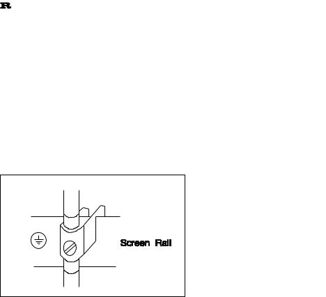
C)The screen connection of the signal lines and the power cables has to be ensued on a screen linequaranteeing enough space. This screen line also has to be conductable and connected to
the remaining housing parts.
D)The cable to the regeneration resistor has to be screened. The screen connection should be on both sides.
E)The mounting of the mains filter has to be situated at the input of the cabinet or behind the transformer. The filter is to connect on ground (cabinet housing, mounting plate etc.).
F)Wiring has to be conducted bundled and close to the cabinet housing or at the mounting line. The unused leads of a cable have to be connected on one side with ground. 1)
G)In case of worse potential balance between the screen connections a compensating leak with at least 10mm2 (AWG) has to be provided parallely in addition to reduction of the screen current.
1)Grounding in general describes all metal parts which can be connected to a protective conductor, e.g. housing of switch cabinet, motor housing, fundament grounder.
1.5.2 Specifications and Additional Components
1.5.2.1 Mains Filter
Following results are desired through the application of mains filters:
The electronic system should be protected from high frequency interferences which could enter via the mains cable (immunity from noise) and vice versa the mains cable may not transmit interferences from the electro-nic systems to the adjoining components (elimination of radio interference).
In the main line a mains input filter has to be provided between transformer and controller (In case of direct connecton this has to be in front of the controller).
To choose the fitting mains filter types following points have to be considered:
1.The need of power of the connected controller. Thereby the capacity and the ability of peak phase current has to be considered.
2.The required or prevailing mains impedance.
This table shows the corresponding mains filter types for 3 phase input:
|
|
Rated Voltage |
Rated Current |
Leakage |
Power |
Weight |
BALDOR |
Type |
|
(at 40°C) |
Current |
Losses |
|
- |
|
|
|
[V] |
[A] |
[mA] |
[W] |
[kg] |
ID-No |
FN 351 - 8 - 29 |
3x 440 |
8 |
16 |
8.0 |
1.8 |
24667 |
|
FN 351 - 16 |
3x 440 |
16 |
16 |
9.0 |
1.8 |
24668 |
|
FN 351 - 25 |
3x 440 |
25 |
170 |
9.0 |
3.0 |
24669 |
|
FN 351 |
- 36 |
3x 440 |
36 |
170 |
10.5 |
3.0 |
24670 |
FN 351 |
- 50 - 29 |
3x 440 |
50 |
190 |
12.5 |
3.1 |
24671 |
FN 351 |
- 80 - 29 |
3x 440 |
80 |
210 |
26.0 |
9.5 |
24672 |
FN 351 |
- 110 - 29 |
3x 440 |
110 |
210 |
28.0 |
9.5 |
24673 |
1.5.2.2 |
Connection Cables |
4 |
|
|
|
|
|||
All cables have to be screened. |
|
|
||
|
|
|
|
|
|
|
Motorcable and Signalcable |
BALDOR |
|
|
|
ID - No. |
||
|
|
|
|
|
|
|
Motorcable |
4 x 1.0 mm2 |
21599 |
|
|
Motorcable |
4 x 2.5 mm2 |
21364 |
|
|
Motorcable |
4 x 6.0 mm2 |
21597 |
|
|
Resolvercable |
3 x [2 x 0.14 mm2] |
19413 |
|
|
Regen Resistorcable |
3 x 2.5 mm2 |
11302 |
1.5.2.3 |
Screen Connection |
|
|
|
Siemens Clamp |
|
Siemens -No. |
||
|
|
|
|
|
5mm Rail |
Wiring Diameter |
8US19 21 |
-2AA00 |
|
|
1.5 - 16 mm2 |
|||
|
1.5 - 35 mm2 |
|
-2AB00 |
|
|
16 |
- 70 mm2 |
|
-2AD00 |
|
16 |
- 120 mm2 |
|
-2AC00 |
10mm Rail |
Wiring Diameter |
8US19 41 |
-2AA00 |
|
for T- and double T-profile |
95 |
- 300 mm2 |
||
|
|
|
|
|
1.5.2.4 Connectors
Connection |
Designation |
BALDOR - ID -No. |
||
for Motorcable |
|
|
|
|
Plug |
CONN SET FEM |
2 x 4 pole |
|
24654A |
Socket |
CONN SET MALE |
2 x 4 pole |
|
24656A |
|
|
|
|
|
for Resolvercable |
|
|
|
|
Plug |
CONN SET FEM |
12/6 pole |
|
24655A |
Socket |
CONN SET MALE |
12/6 pole |
|
24657A |
|
|
|
|
|
|
for BSC with EMC-Regulation |
|
|
|
|
connector X2 with housing |
|
|
|
Connector |
|
|
25043A |
|
Housing |
|
|
25049A |
|

5
1.5.2.5 PG - Cable Glands
PG Cable Gland |
Cable Dimensions |
Designation |
BALDOR |
|
|
|
ID - No. |
|
4 - 8 mm |
SCREWING |
24658 |
PG 9 |
Resolvercable |
|
|
|
BALDOR ID-No.19413 |
|
|
|
6 - 12 mm |
SCREWING |
24659 |
PG 13.5 |
Motorcable |
|
|
|
BALDOR ID-No. 21599 |
|
|
|
13 - 18 mm |
SCREWING |
24660 |
PG 21 |
Motorcable |
|
|
|
BALDOR ID-No. 21364 |
|
|
1.6 Technical Data
All values at Tamb = 40 °C, if not otherwise specified.
1.6.1 Power Section
General |
Unit |
BSC |
BSC |
|
BSC |
BSC |
BSC |
BSC |
BSC |
|
|
2015 |
2025 |
|
2035 |
2045 |
3015 |
3025 |
3035 |
Nominal DC-Bus-Voltage |
VDC |
|
|
320 |
|
|
- |
|
|
Uin (BPS) = 230V |
|
|
|
|
|
||||
Nominal DC-Bus-Voltage |
VDC |
|
|
- |
|
|
560 |
|
|
Uin (BPS) = 400V |
|
|
|
|
|
||||
Nominal DC-Bus-Voltage |
VDC |
|
|
- |
|
|
650 |
|
|
Uin (BPS) = 460V |
|
|
|
|
|
||||
DC-Bus-Voltage |
VDC |
|
0 ... 350 |
|
|
0 ... 740 |
|
||
absolute min./max. |
|
|
|
|
|||||
|
|
|
|
|
|
|
|
|
|
Output Voltage Line/Line |
VRMS |
|
0 ... 250 |
|
|
0 ... 500 |
|
||
fundamental wave; @VDC-Bus (nom.) |
|
|
|
|
|||||
Nominal Phase Current (±10%) |
ARMS |
15 |
25 |
|
35 |
45 |
15 |
25 |
35 |
Peak Phase Current (±10%) |
ARMS |
30 |
50 |
|
70 |
90 |
30 |
50 |
70 |
1.5s ±0.5s |
|
||||||||
|
|
|
|
|
|
|
|
|
|
Nominal Output Power |
kVA |
6.5 |
10.8 |
|
15.1 |
19.5 |
13.0 |
21.6 |
30.3 |
Efficiency |
% |
|
|
|
|
> 95 |
|
|
|
Min. Load Inductance |
μH |
|
|
|
|
200 |
|
|
|
Output Frequency |
Hz |
|
|
|
|
0 ... 500 |
|
|
|
Nominal Switching Frequency |
kHz |
|
|
|
|
8.5 |
|
|
|

6
1.6.2 24VDC Input
|
24V-Input |
Unit |
BSC2000 |
|
BSC3000 |
|
Input Voltage Range |
|
|
|
|
|
absolute min./max. |
VDC |
|
20 ... 29 |
|
|
max. VRipple = ±10% |
|
|
|
|
|
Input Current; @ 28VDC |
ARMS |
|
1.6 |
|
|
Surge Current at Power On |
ARMS |
|
2.5 |
|
|
@ 28VDC; @ 100ms |
|
|
|
|
1.6.3 Velocity Controller |
|
|
|
|
|
Preamplifier |
Unit |
BSC2000 |
|
BSC3000 |
Command Input |
VDC |
|
0 .. ±10 |
|
Drift (velocity controller) |
rpm/K |
|
0.4 |
|
Balance (velocity controller) |
rpm |
|
typ. 8; adjustable to 0 |
|
|
Resolverfeedback |
|
Unit |
BSC2000 |
|
|
BSC3000 |
|
Resolution |
|
bit |
|
12 |
|
|
|
Encoder-Simulation |
|
ppr |
250 / 500 / 1000 / 1024 |
|||
|
Signal |
|
|
5V TTL ; A;A/; B;B/; C;C/ |
|||
|
Reference Pulse |
|
|
available; non adjustable |
|||
1.6.4 Mechanical |
Section |
|
|
|
|
||
|
|
|
|
|
|
|
|
|
Mechanical |
|
Unit |
BSC2000 |
|
|
BSC3000 |
|
Mounting |
|
- |
Bookstyle or Thru the Wall |
|||
|
Dimensions |
|
mm |
105 x 357 x 328 |
/ 140 x 357 x 328 1) |
||
|
Weight |
|
kg |
8.5 |
/ |
|
9.5 1) |
1) |
: BSC2045/3035 |
|
|
|
|
|
|
7
1.6.5 Environmental Section
Environmental |
Unit |
BSC2000 |
|
BSC3000 |
Operating Temperature Range |
°C |
|
+5 ... +45 |
|
Storage Temperature Range |
°C |
|
-25 ... +70 |
|
Humidity |
% |
10 ... 90; not condensating; according to DIN40 040, Class F |
||
Class of Protection (Enclosure) |
- |
IP20; according to DIN40 050 / IEC 144 |
||
Max. Installation Altitude / M.S.L. |
m |
|
1000 |
|
Shock |
- |
10G; according to DIN IEC 68-2-6/29 |
||
Vibration |
- |
1G; 10 ... 150 Hz; according to DIN IEC 68-2-6/29 |
||
Legend:
This is an INFORMATION sign.
If this information is read, installation and / or amplifier operating problems can be avoided in advance.
This sign means ATTENTION.
In all cases it must be read and taken into account.
Non-observance can cause dangerous situations for equipment and personnel.
2.0Installation Recommendations
2.1Mechanical Installation
-For installation of your system use a cabinet with a protection class that suits your environmental conditions.
-As cooling air freely enters the unit, the environment must be free from corrosive chemical substances, oil, vapour, steam, metal particles and dust.
-Make sure that cooling is provided.
-Make sure that the top of the unit is covered during installation to prevent particles from falling into the unit.
-Keep DC-bus links as short as possible. Therefore always mount BSC2000/3000-combinations side by side.
-Mount all BSC vertical (Terminal blocks to the top).
-Use BSC2000/3000 in stationary groundbased applications only.
 Loading...