

Page 1
A64 CS Stacker Quick Reference
This Quick Reference contains supply loading information, setup, general care, and maintenance procedures for
the Avery Dennison® A64 Cutter/Stacker. For more detailed information, refer to the Operator’s Handbook
available on our Web site (www.monarch.com).
Information in this document supercedes information in previous versions. Check our Web site for the latest
documentation and release information.
Warning:
This equipment generates, uses, and can radiate radio frequency energy and if not installed and used in
accordance with the instruction manuals, may cause interference to radio communications. It has been tested and
found to comply with the limits for a Class A computing device pursuant to Subpart J of Part 15 of FCC Rules,
which are designed to provide reasonable protection against such interference when operated in a commercial
environment. Operation of this equipment in a residential area is likely to cause interference in which case the user,
at his own expense, will be required to take whatever measures may be required to correct the interference.
Getting Started
1. Set up your printer. Refer to the documentation provided with your printer for more information.
2. Unpack the stacker and packing material from the box.
The box should contain:
• Stacker base and tray assembly (with the “Stacker Full” cable attached to tray)
• Power cord and stacker interface cable
3. Set the stacker to the left side of the printer.
4. Alignment the printer to the stacker.
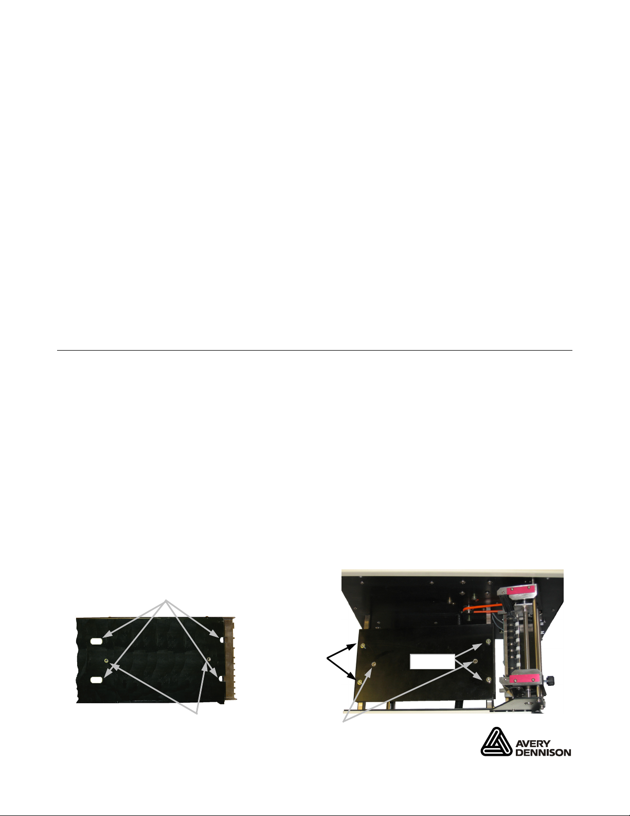
5. Attach the stacker tray assembly.
• Align the slotted holes of the tray with the studs on the stacker base.
• Align the fingers of the tray with grooves on the top rollers.
• Center the two screw holes and start the captive screws from underneath the base. Make
sure the tray fingers do not touch the black transport roller.
• Tighten the screws.
Underside of Tray
Slotted Holes
Screw Holes
Studs
Captive Screws
Studs
Top view of Base
TC9864CSQR Rev. AA 6/08 ©2008 Avery Dennison Corp All rights reserved.
Page 2
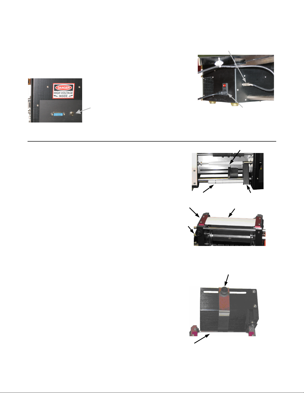
6. Connect the stacker full cable and stacker communication
r
r
cable between the stacker and your printer.
7. Plug the power cord to the stacker and the other end into a
grounded electrical outlet.
Communication Cable
Communication Cable
Connecto
Connecto
Threading Supply
Stacker Full Cable
Power Cord
1. Make sure the stacker is disabled. The stacker is disabled
when the READY light is red.
2. Threading tags between tag guides:
• Thread tags under the dancer rollers and push against
the fixed guide.
• Slide the outer tag guide towards the tags leaving
space between the guides for the tags to move freely.
3. Set the pusher tag width:
Outer Guide
• Loosen the thumbscrew on the outer tag
pusher.
Thumbscrew
• Place a sample tag between the guides and
slide the outer guide towards the tag leaving
space between the guides for the tags to
move freely.
• Tighten the thumbscrew.
4. Adjust the tag stack support bar:
• Loosen the thumbscrew on the tag support bar.
• Slide the bar left or right to the middle of the tags.
Dancer Rollers
Thumbscrew
Outer Guide
Fixed Guide
Sample Tag
• Tighten the thumbscrew.
Sample Tag
2
Page 3
5. Adjust the side bar guide:
• The side bar is attached with magnets.
• Align the side bar with the notch of the outer tag
pusher. Make sure the side bar is parallel to the
edge of the tray.
ote: Adjust the sensors if you use tags with a
N
notch, swiftach hole, or a flag document.
Side Bar Guide
Notch
See “Making Sensor Adjustments” for more information.
6. Press START/STOP to enable the stacker.
The READY light is green when the stacker is enabled and ready to cut and stack tags. When the printer begins
printing, the stacker automatically feeds, cuts, and stacks the tags.
Note: After pressing START/STOP, if the stacker does not see the notch or sensor mark within
16 inches of supply, the stacker automatically disables and the READY light turns red.
Making Sensor Adjustments
The stacker uses three types of sensors: the transmissive sensor, the flag sensor, and the reflective sensor.
Test sensors by feeding tags through the stacker. To feed tags, disable the stacker and advance tags by manually
turning the feed roller. If the NOTCH light does not light, the sensors may need to be adjusted.
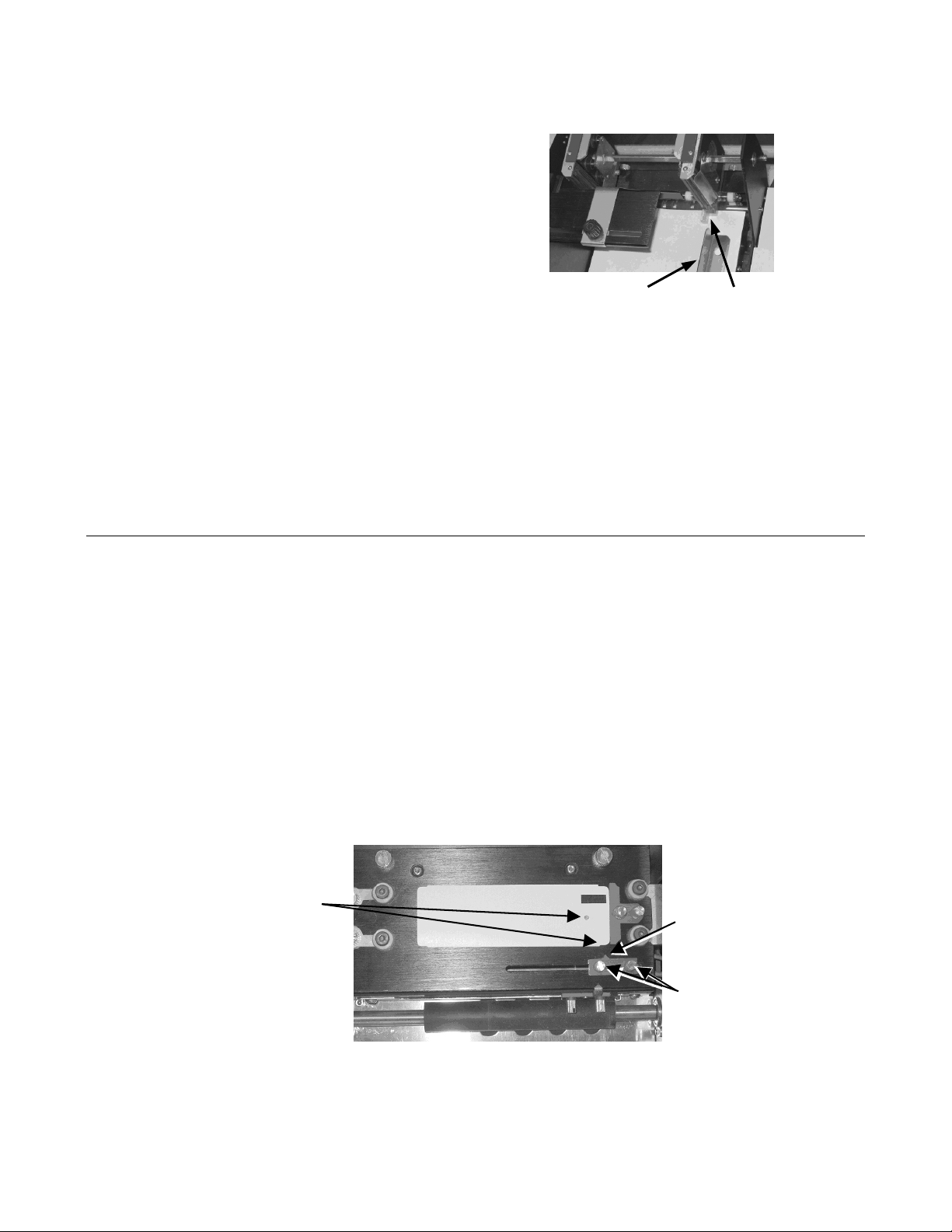
Setting the Transmissive Sensor
The transmissive sensor is located on the front of the knife assembly and is used for cutting tags with a notch or a
Swiftach hole.
Note: When the position of the transmissive sensor is set correctly, the NOTCH light flashes as
tags pass the sensor.
• Make sure the stacker is disabled. The stacker is disabled when the READY light is red.
• Place a sample tag against the guide on the knife assembly.
• Loosen the sensor thumbscrews and slide it until the arrow is pointing to the notch or hole.
• Tighten the thumbscrews.
Align Arrow with
Notch or Hole
Arrow
Thumbscrews
3
Page 4

Setting the Flag Sensor
The flag sensor is located on the bottom of the knife assembly and is used to cut tags with a printed
flag mark.
Note: When the position of the flag sensor is set correctly, the FLAG light flashes as tags pass
the sensor.
• Make sure the stacker is disabled. The stacker is disabled when the READY light is red.
• Place a sample tag against the guide on the knife assembly.
• Loosen the sensor thumbscrews and slide it until the arrow is pointing to the middle of the flag mark.
• Tighten the thumbscrews
•
Flag Mark
Arrow
Thumbscrews
Setting the Reflective Sensor
The Reflective Sensor is located behind the knife assembly, visible from the bottom of the stacker.
The reflective sensor can be moved by hand. Normally, no adjustment is necessary for this sensor.
4
Page 5

Power On/Off
r
1. Turn on the circuit breaker, then turn on the power
switch.
Using the Control Panel
The following table describes how to use the control panel to set up the stacker.
Circuit Breaker
Power Switch
Indicator/Key Description
START/STOP
FEED
MODE
ARROW KEYS
POWER
READY
FLAG
NOTCH
ERROR
LCD Display
Enables and disables the stacker. When the stacker is disabled, the
READY light is red. The stacker does not cut or feed tags, but the
feed roller can be turned by hand. When the stacker is enabled, the
READY light is green. As tags are ready from your printer, the stacke
feeds, cuts, and stacks the tags.
Advances one tag.
Sets the stacker’s operating mode. Modes can be changed to use the
stacker with different kinds of tags or allow service procedures like
calibration to be performed. See “About the Menu Overview” for more
information about modes.
Sets modes and toggling between options.
Indicates the power is on, when lit.
Indicates the stacker is ready to cut and stack, when green.
Indicates that the stacker is disabled, when red.
Flashes when a sensor mark is detected.
Flashes each time the sensor sees a tag notch, a sensor mark, or a
Swiftach hole.
Indicates an error, when flashing. Check the display for the error
message.
Shows error messages and mode settings.
5
Page 6

About the Menu Overview
The stacker has three mode menus shown below.
Press the MODE key to navigate through the main menu and display each mode.
Press START/STOP to select a mode. Use the ARROW keys to select options within a mode.
Mode Selection Customize Modes Service & Diagnostics
1. Standard Notch 1. Standard Cut Master Cutline Adjustment
2. 1.222 Swiftach 2. 1.222 Swiftach Sensor Status
3. 1.250 Swiftach 3. 1.250 Swiftach Cycle Count
4. 1.375 Swiftach 4. 1.375 Swiftach Reset to Factory Defaults
5. User defined 5. User defined Motor Tests
6. User defined 6. User defined Web Test
7. User defined 7. User defined Knife Motor Test
8. User defined 8. User defined Transport Motor Test
9. User defined 9. User defines Pusher Motor Test
10. User defined 10. User defined Check LCD
Check Keypad
Check Memory
For each specify: For each specify: Sensor Trip Points
Flags? YES/NO/EXT Sensor Type: Transmissive Sensor Adjust
Transmissive Reflective Sensor Adjust
Reflective Flag Sensor Adjust
Offset: mm LCD Contrast Adjustment
Speed Setup
Note: Modes 5 through 10 display in Mode Selection only after they are defined in the
Customize Modes menu.
6
Page 7

Cleaning
1. Turn off the stacker.
2. Remove any tags.
3. Pull the black release block to open the knife assembly.
4. Use compressed air or a small brush to clean the sensors.
5. For better access to the sensors, loosen the transport thumbscrews and remove the transport assembly.
6. Install the transport assembly.
7. Close the knife assembly.
8. Clean the feed roller.
Transport Thumbscrews
Release Block
Knife Swing Assembly
Feed Roller
7
Page 8

Error Messages
Error Messages are shown on the display and the ERROR light flashes. Press STOP/START to clear the error
message and return to READY.
Error Action
OUT OF PAPER
PAPER JAM
PUSHER JAM
KNIFE JAM
STACKER FULL
INTERLOCK OPEN
INTERNAL ERROR 01
There are no tags in the stacker. Check to see if
the printer is out of supply.
Tags have jammed in the stacker or the sensor is
blocked or dirty. Check the paper path for the jam.
Make sure the sensor is positioned properly and
is not blocked. Clean the sensor.
The pusher assembly is jammed. Check for
proper alignment of the pusher assembly. The
pusher assembly is where tags are guided and
pushed onto the stacker. Look for blockage in the
stacker area.
Tags are jammed at the knife.
Remove any jammed tags.
The stacker tray is full of tags. Remove the
stacked tags from the tray.
The knife assembly is open, or the plastic shield is
not secure (if so equipped). Close the knife
assembly or plastic shield so it is completely
latched.
An internal time-out occurred. Use Motor on the
Service & Diagnostics menu to check all motors
for proper functioning.
CONFIRM MODES
If you cannot fix a problem, call service.
8
The non-volatile RAM area is not initialized, or the
RAM area is corrupted. Set the proper modes and
continue.
 Loading...