

Page 1

QUICK REFERENCE
This Quick Reference contains supply loading and general
care and maintenance procedures for the Monarch 9860
printer. For more detailed information, refer to the Operator’s
Handbook available on our Web site (www.monarch.com
Note: Information in this document supercedes information
in previous versions. Check our Web site for the
latest documentation and release information.
Connecting the Cables
The power supply automatically switches between 115V or
230V. There are no operator settings required.
1. Plug the power cable into the socket. Plug the other end
of the cable into a grounded electrical outlet.
2. Connect the communication cable into the appropriate
port. Secure the cable with the connecting screws (serial)
or spring clips (parallel).
If you are communicating with the host through the serial
port, make sure the printer's communication values match
those at the host. The factory default values are 9600
Baud, 8 bit data frame, 1 stop bit, no
parity, and DTR flow control. Set the
communication values on the printer to
match those at the host.
The printer also has a USB (Universal
Serial Bus) version 2.0 communications
port, which is compatible with version
1.1. Drivers are available on our Web
site for a variety of operating systems.
These drivers provide a Virtual
Communications Port (VCP), which
looks like a normal serial port (for
example, COM1-4).
After installing
the drivers, change the
communications port to
the one allocated by the
VCP driver.
3. Turn on the printer. Press ( I ) to turn
on and ( O ) to turn off the printer.
Monarch and 9860 are registered trademarks of Avery
Dennison Retail Information Services LLC. Avery
Dennison is a trademark of Avery Dennison Corp.
TC9860QR Rev. AE 11/09 2003 Avery Dennison Corp. All rights reserved.
Parallel Port
USB Port
Serial Port
Power Cable
Goes Here
).
Page 2
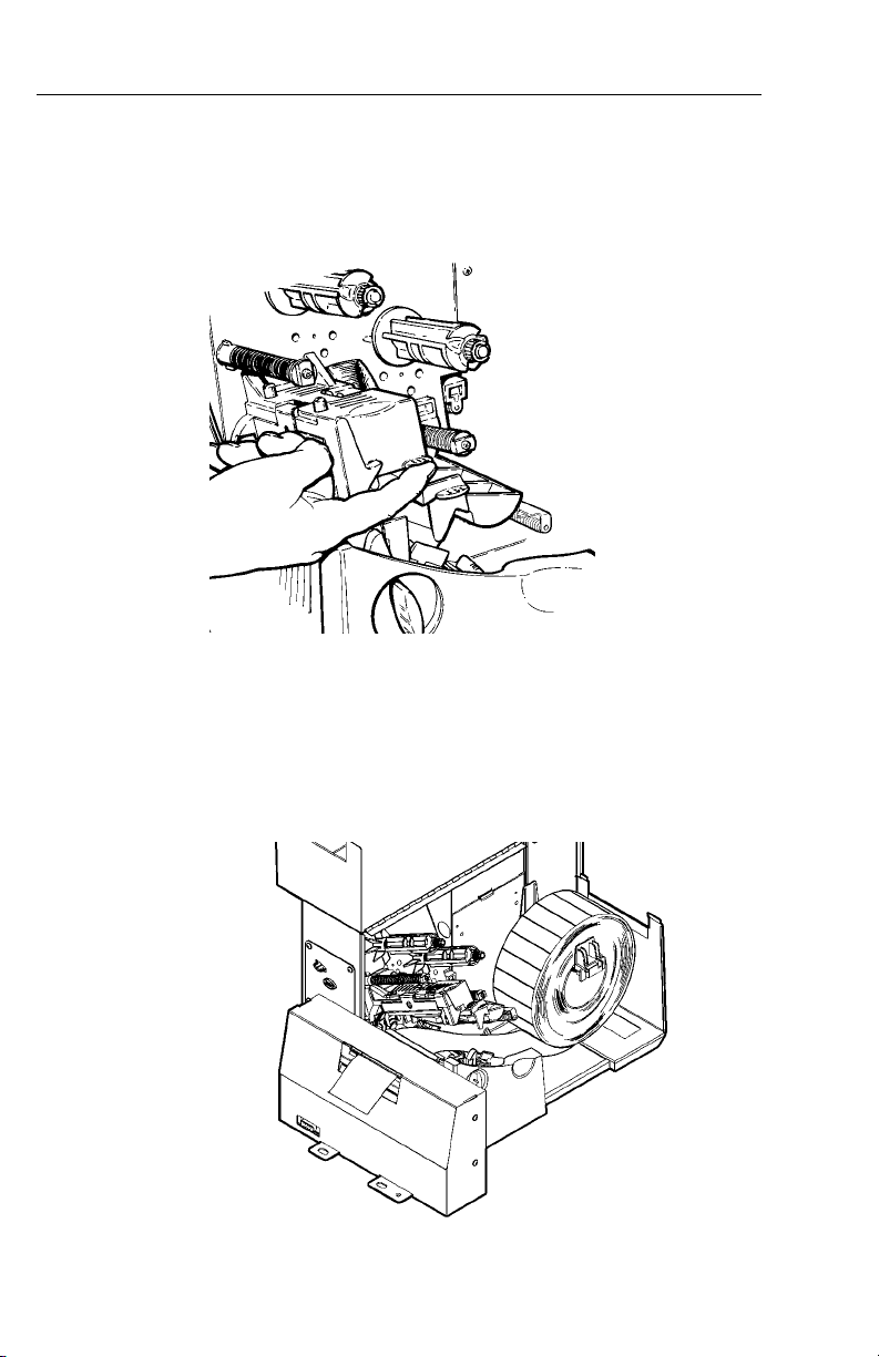
Loading Tags or Labels
1. Open the cover.
2. Unlock the printhead by turning the retaining latch.
3. Lift printhead assembly using the printhead tab until the
assembly locks into place.
4. Place the roll of supply on the supply holder. For tags,
make sure the supply unrolls from the bottom, because
tag rolls are wound face in. For labels, the supply unrolls
from the top or the bottom. Do not pick up the printer
by the supply holder.
5. Adjust the supply holder guides so the sides barely touch
the roll. Make sure the supply roll turns freely.
2
Page 3
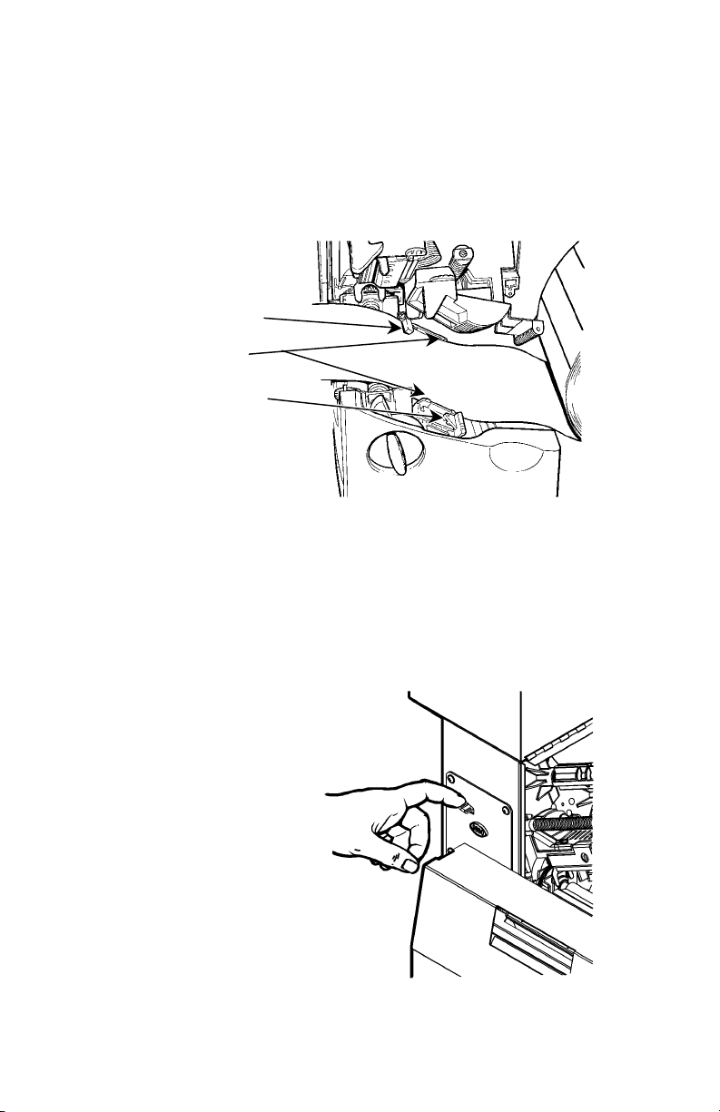
6. Push down on the supply lever to unlock the supply
guides.
7. Lay the supply into the feed path. Tuck the supply under
the nibs and in between the die cut sensor. Do not feed
supply between the supply roller and deflector.
8. For tags or labels, feed the supply between the upper
and lower knife guides with at least 0.5 inches of supply
through the knife.
Die Cut Sensor
Nibs
Supply Lever
For labels, your System Administrator should use cut
mode 5 to cut in strips. Refer to the Packet
Reference Manual for more information. There may
be one or two blank labels left between the printhead
and knife after the last batch.
9. Adjust the supply guides so they touch the supply. Push
up on the supply lever to lock the supply guides into
place.
10. Hold the printhead
assembly by the
printhead tab while
pressing down on the
printhead release.
3
Page 4

11. Close the printhead by
pressing down on the
thumb well until you
hear it click into place.
12. Close the cover.
13. On the keyboard, press
Feed (F) to position
the supply under the
printhead and through
the knife.
Adjusting the Wide/Narrow Knobs
You may need to adjust the two wide/narrow knobs according
to the width of your supply. For supply that is more than two
inches, adjust the knobs to the wide setting. For supply that is
two inches or less, adjust the knobs to the narrow setting.
You must adjust both of the knobs to the same position.
If you experience ribbon
smudging in cold, dry
environments, adjust the
wide/narrow knobs to the
wide setting.
For wide supplies, push
down and turn the
wide/narrow knobs
clockwise with a
screwdriver.
For narrow supplies, turn
the wide/narrow knobs counter-clockwise with a screwdriver
until it pops back up.
The adjustment is shown in the wide position.
4
Page 5

Loading Ribbon
1. Open the cover.
2. Unlock the printhead by
turning the retaining
latch.
3. Lift printhead assembly
using the printhead tab
until the assembly locks
into place.
4. Push the deflector tab
down.
5. Slide the extra ribbon
core on the take-up reel
as far as it will go with
the "This End Out"
writing facing out. Use
your empty ribbon core as the take-up core. The take-up
core only fits on the take-up reel one way.
6. Remove the new ribbon from the package. Do not wrinkle
or crush the new ribbon.
7. Slide the ribbon onto the back reel as far as it will go.
The ribbon roll only fits on the reel one way. Carefully
unwind a few inches of ribbon from the bottom of roll.
Printhead
Tab
Deflector
Tab
Take-up
Core
Take-up
Reel
Ribbon
Rollers
Note: Make sure the “Monarch This End Out” writing is
facing out. The ribbon roll only fits on the reel one
way.
8. Carefully feed the ribbon under both ribbon rollers and
printhead.
5
Page 6

9. Align the ribbon and make sure it is straight and centered
throughout the path.
10. Tape the ribbon to the take-up core. Do not tape the
ribbon to the take-up reel.
11. Rotate the take-up core until the leader is past the
printhead.
12. Remove any slack in the ribbon by turning the take-up reel
clockwise.
13. Hold the printhead assembly by the printhead tab while
pressing down on the printhead release.
14. Close the printhead by pressing down on the thumb well
until you hear it click into place. Close the cover.
Printing
Before you print, make sure the printer is connected and ready
to receive data.
1. Turn on the printer. The printer is ready to receive and
print batches when you see “PRINT MODE Ready” on the
keyboard.
2. Download a format and a batch. Refer to the optional
Packet Reference Manual for information on downloading
print jobs.
3. The printer prints the format.
4. Remove the printed supply. If the printer will be unused
for extended periods of time, we recommend leaving the
printhead unlatched.
Clearing Jams
When you are printing and a jam occurs, an error appears on
the keyboard.
1. Turn off the printer and open the cover and printhead
assembly.
2. If necessary, remove the supply roll and ribbon.
3. Remove the jammed supply and reload the supply roll.
4. Close the printhead assembly and turn on the printer.
5. On the keyboard, press Feed (F) to position the supply
under the printhead.
6
Page 7

Knife Maintenance
The knife alerts you when it requires maintenance. When the
knife reaches three million cuts and the printer is turned on,
the keyboard briefly displays
Service Knife Soon
Each time you turn on the printer, this message appears and
then disappears. Call Service to schedule an appointment for
knife maintenance.
If you ignore this message, the printer eventually displays
“Knife Jam” and the knife stops working. You must press
Escape (E) to clear the error and the knife may cut a few
more tags before it stops working.
Cleaning
You must clean the printhead as described below to maintain
printhead life.
CAUTION: Do not use sharp objects to clean the printhead or
touch the printhead. This may damage the
printhead and require a service charge.
The rate and frequency at which you print determines how
often you must clean the printer. You may need to clean the
printhead, sensor, and platen roller:
♦ if there is any adhesive build-up in the
supply path.
♦ after printing approximately 3 rolls of
thermal transfer/thermal direct supplies
or after each ribbon.
♦ daily if your printer is in an excessively
dirty, hot, or humid environment.
♦ if you frequently receive supply error
codes or when you see voids or
streaking in the print as shown.
1. Turn off the printer and open the cover and printhead
assembly.
2. Remove the label roll and ribbon (when cleaning the
printhead).
Voids
Streaks
7
Page 8

3. Clean the platen roller when you see significant
adhesive build-up or a label is wrapped around the
platen roller. Use a dry, soft-bristle brush, such as a
toothbrush, to clean either the standard (black) or
linerless (red/orange textured) platen roller.
If the brush does not remove all the adhesive
♦ use isopropyl alcohol ONLY on the standard (black) platen
roller.
Moisten a cotton swab with isopropyl alcohol and run the
cotton swab across the platen roller. Turn the platen roller
with your finger to make sure the platen roller is clean all
the way around.
After cleaning, feed several inches of supply through
without printing to remove any remaining isopropyl
alcohol.
♦ call Service to clean the linerless (red/orange textured)
platen roller.
Note: Do not use alcohol or solvents on linerless
(red/orange textured) platen rollers.
4. Rub the cotton swab moistened with isopropyl alcohol
across the peel bar and remove any build-up.
5. Moisten another cotton swab with isopropyl alcohol. Rub
the cotton swab across the printhead and remove any
build-up. You may need to use a printhead CLEAN-STRIP
if the printhead is extremely dirty or you see streaks on
the supply.
8
Printhead
Page 9

6. Rub the cotton swab across the supply sensor and die cut
sensor and remove any build-up.
Die Cut
Sensor
Supply
Sensor
7. Clean the build-up in the supply path.
8. Let the printer dry before you reload supplies.
9. Close the cover and printhead assembly.
10. Turn on the printer. On the keyboard, press Feed (F) to
position the supply under the printhead and through the
knife. Resend your format, batch, and check digit
packets.
Troubleshooting
This section provides solutions to minor printing problems.
For more detailed information, refer to the Operator’s
Handbook available on our Web site.
Problem Action
Error message
appears during
startup
Turn off the printer, wait fifteen
seconds and then turn on the
printer. Call Technical Support if
the error message reappears.
Does not print.
Check supply and ribbon.
Send a corrected format and batch
packet.
Does not feed. Set wide/narrow knobs correctly.
Partially printed
data.
Printing shadows or
smears.
Clean the printhead.
Send a corrected format packet.
Clean the printhead, change
supply, and check the ribbon.
9
Page 10

Problem Action
Light Printing.
-or-
Heavy Printing.
Voids in printing.
Serial bar codes do
not scan.
Backing paper is
wrapped around
platen or peel roller.
Blank labels print or
750 series errors.
Clean the printhead, change
supply, adjust the print contrast.
Check the wide/narrow knobs and
check the ribbon.
Clean the printhead, change the
supply type, and check the ribbon.
Leave printhead unlatched when
not in use, use a print speed of
2.5 IPS, and adjust the print
contrast.
Carefully remove the backing
paper. Make sure the backing
paper tears at the saw-toothed
tear edge when using backfeed
and peel mode.
Clean the supply sensors.
Common Errors
Error Description/Action
002
005
018
025
101
400
403
409
410
411
412
413
611
Name must be 1 to 8 characters inside quotes.
Supply width is invalid.
Code page selection defined in the field is
invalid.
Data length is too long.
Format referenced by batch not in memory.
Invalid character following { .
Field separator was not found.
Printer memory is full. Delete unnecessary
formats or graphics from memory.
Parity mismatch.
Framing error (baud rate mismatch).
Flow control mismatch.
Online receive buffer is full. Check for a flow
control problem.
Font, bar code, or density in the batch does not
fit the format.
10
Page 11

612
613
614
703
704
The data in this line of the batch is either
missing or does not match the format.
Reference point off supply.
Portion of field off supply or there may be an
invalid character in the packet.
The printer sensed a calibration of differentsized black marks. Make sure the correct
supply type is loaded.
Printer has not sensed a supply mark when
expected or is out of supplies. Press Escape
(E) to continue printing. Change supply.
751
752
753
754
755
756
757
758
763
764
765
Printer did not sense a black mark when
expected. Press Escape (E ) and try to
continue printing. Change supply.
Printer sensed a mark in the wrong place.
Printer sensed a mark that is too long.
Check for a ribbon jam or remove any slack in
the ribbon by turning the take-up reel clockwise.
Load a new ribbon.
Printhead is open. Close the printhead.
Load supplies.
Load supplies (supply length mismatch). Press
Feed (F).
Either the supply is not seen, the on-demand
sensor is broken, or a label was removed too
quickly. Check for a label jam or reload
supplies.
Waiting to dispense label. Press Feed (F).
Verifier scan error. Press Escape (E ) to clear
the error and continue printing.
The printhead has less than 8 bad dots and can
shift bar code fields to avoid bad dots. Press
Escape (E) to continue printing.
768
Printhead has more than 8 bad dots within the
format area or is not connected. Connect
printhead.
11
Page 12

Tag Cut Dimensions
Widths:
Lengths:
Note:
Batch
Separator:
Cut Angle:
Total
Thickness:
1.0 inches to 4.0 inches
(25 mm to 102 mm)
1.5 inches to 16.0 inches (38 mm to 406
mm). This printer allows cutting 1.2 inch
(30 mm) feed length tags at 8.0 ips;
however, optimal cut quality may not be
achieved.
The maximum cut length using the stacker
is 3.66 inches (93 mm)
3.66 inches (93 mm)
1° (plus or minus) from 90° with respect to
the edge
9 mils to 12 mils (tags)
5.5 mils to 12 mils (labels)
12
 Loading...