

Page 1
Operator's Handbook
28028
0
Monarch 9855
®
Printer
®
TC9855OH Rev. AJ 5/15
345
2
Sh
Dayt
ip
6
Fr
on,
01
9
8
7
6
5
4
3
2
From:
ip
8901
7
56
4
3
2
01
9
78
:
m
o
o
Ohi
Sh
a
D
©2003 Avery Dennison Corp. All rights reserved.
:
om
r
F
p
i
yton, Ohio
Sh
Da
y
ton
h
O
,
Page 2

Each product a nd program carr ies a respective wr itten warrant y, the only warrant y
on which th e customer can rely. A very Dennis on Corp. r eserves th e right to m ake
changes in the pr oduct, the progr ams, and their av ailability at an y time and without
notice. A lthough Aver y Denniso n Corp. has m ade ever y effort to pr ovide com plete
and accurate i nformation in th is manual, Aver y Dennison Corp. sha ll not be liable
for any omissio ns or inaccuraci es. Any update will be incorporated in a later
edition of this manua l.
2003 Avery Den nison Corp. All rig hts reserved. No part of this publicatio n may
be reproduc ed, transm itted, stor ed in a retr ieval syst em, or trans lated into any
language in an y form by any means, wi thout the prior wr itten permission of Avery
Dennison Corp.
WARNING
This equipm ent has been tested and found to c omply with t he limits f or a Class A
digital device , pursuant to Part 15 of the FCC Rules. Thes e limits are des igned to
provide reaso nable protect ion against harmf ul interference when the equipm ent is
operated in a commer cial environm ent. This e quipment g enerates, us es, and ca n
radiate radi o frequency energ y and, if not instal led and used in accor dance with
the instruc tion manua l, may cause harmful i nterferenc e to radio c ommunicat ions.
Operation of this equip ment in a r esidential area is lik ely to cause harmful
interferenc e in which c ase the us er will be r equired to c orrect th e interfer ence at
his own expe nse.
CANADIAN D.O.C. W ARNING
This digital apparatus does not ex ceed the Class A lim its for rad io noise
emissions f rom digita l apparatus set out in t he Radio In terference Regulations of
the Canadia n Departm ent of Comm unications.
Le présent a ppareil nu mérique n ’émet pas de bruits rad ioélectriq ues dépassan t
les limites app licables aux app areils numériq ues de la classe A pr escrites dans l e
Réglement s ur le brou illage radi oélectrique édicte p ar le ministèr e des
Communicat ions du Cana da.
Trademarks
Monarch, 7411, 9825, 9850, 9855, and 9860 are trademarks of Avery Dennison Retail Information
Services LLC.
Avery Dennison® is a trademark of Avery Dennison Corp.
HP Jet Admin and HP Web Jet Admin are trademarks of Hewlett-Packard, Inc.
Hewlett-Packard is a registered trademark of of Hewlett-Packard, Inc.
Centronics is a registered trademark of Centronics Data Computer Corporation.
TrueType is a registered trademark of Apple Computer, Inc.
Other products are trademarks or registered trademarks of their respective countries and are hereby acknowledged.
Avery Denn ison Printer Systems Di vision
170 Monarch Lane
Miamisburg , OH 45342
Page 3

TABLE OF CONTENTS
GETTING STARTED ....................................................................................... 1-1
Audience.................................................................................................. 1-2
Using this Manual ..................................................................................... 1-2
Unpacking the Printer ............................................................................... 1-3
Shipping the Printer ............................................................................... 1-3
9445™ Printer Online Emulation ................................................................ 1-4
Ordering Programmer's Manuals ................................................................ 1-4
About Monarch® MPCL™ Toolbox Utilities.................................................. 1-4
Connecting the Power Cable...................................................................... 1-4
Establishing Communications .................................................................... 1-5
Connecting the Communication Cable ..................................................... 1-5
Using the Control Panel ............................................................................ 1-6
Printer Status Lights .............................................................................. 1-6
Button Functions ................................................................................... 1-6
Display ................................................................................................. 1-7
Selecting a Function ................................................................................. 1-7
Exiting an Option ...................................................................................... 1-8
LOADING SUPPLIES ..................................................................................... 2-1
Loading Labels or Tags ............................................................................. 2-2
Loading Labels for the Optional Peel Mode ............................................. 2-7
Using the Optional Tear Bar ...................................................................... 2-9
Using String Tag Supply .......................................................................... 2-10
String Tag Considerations .................................................................... 2-10
Adjusting the Wide/Narrow Knobs ............................................................ 2-12
Table of Contents i
Page 4

LOADING RIBBON ......................................................................................... 3-1
Loading Ribbon ........................................................................................ 3-2
Using a High Energy Ribbon ...................................................................... 3-4
High Energy Ribbon Limitations .............................................................. 3-5
SETTING SUPPLY OPTI ONS .......................................................................... 4-1
Setting the Supply Type ............................................................................ 4-3
Setting the Ribbon .................................................................................... 4-4
Setting the Speed ..................................................................................... 4-5
Setting the Feed Mode .............................................................................. 4-6
Setting the Backfeed ................................................................................. 4-7
Changing the Position Settings .................................................................. 4-8
Setting the Print Position ....................................................................... 4-8
Setting the Supply Position .................................................................. 4-10
Setting the Margin Position .................................................................. 4-11
Setting the Cut Position ....................................................................... 4-12
Setting the Dispense Position ............................................................... 4-13
Setting the Backfeed Distance .............................................................. 4-14
Using Batch Separators .......................................................................... 4-15
Using Skip Index .................................................................................... 4-16
Setting the Knife Control ......................................................................... 4-17
Setting the Error Action ........................................................................... 4-18
Setting the Print Contrast ........................................................................ 4-20
Enabling the Verifier ............................................................................... 4-22
ii Operator's Handbook
Page 5

SETTING COMMU NICATIONS ........................................................................ 5-1
Setting the Baud Rate ............................................................................... 5-2
Setting the Word Length ............................................................................ 5-2
Setting the Stop Bits ................................................................................. 5-3
Setting the Parity ...................................................................................... 5-3
Setting the Flow Control ............................................................................ 5-4
Resetting to Default Values ....................................................................... 5-4
Using Parallel Communications .................................................................. 5-5
Setting the Port ..................................................................................... 5-5
Setting the Mode ................................................................................... 5-6
SETTING DEFAULTS ..................................................................................... 6-1
Setting the Monetary Sign ......................................................................... 6-3
Setting the Secondary Sign ....................................................................... 6-4
Setting the Number of Decimal Places ........................................................ 6-5
Setting the Slashed Zero Appearance ........................................................ 6-5
Setting the Power-Up Mode ....................................................................... 6-6
Changing the Prompt Set .......................................................................... 6-6
Setting the Numeric Format ....................................................................... 6-7
Using Flash Storage ................................................................................. 6-8
Disabling Image Errors .............................................................................. 6-9
Ignoring Configuration Packets ................................................................ 6-10
Using Error Retry Mode ........................................................................... 6-11
Adjusting the Image Length ..................................................................... 6-12
Using Flash Memory ............................................................................... 6-14
Formatting Flash Memory ..................................................................... 6-14
Checking Available Flash Memory ........................................................ 6-15
Packing Flash Memory ......................................................................... 6-16
Table of Contents iii
Page 6

Memory Guidelines ................................................................................. 6-17
Setting Batch Options ............................................................................. 6-18
Setting Up the Network Printer ................................................................ 6-18
Setting Up the RFID Printer ..................................................................... 6-18
USING SCRIPTS ............................................................................................ 7-1
Initial Script Startup Procedures ................................................................ 7-2
Viewing Script Information ......................................................................... 7-2
Downloading a Script ................................................................................ 7-3
Enabling a Script ...................................................................................... 7-4
Deleting a Script ....................................................................................... 7-5
Enabling Status Polling ............................................................................. 7-6
Using Immediate Commands...................................................................... 7-7
PRINTING ..................................................................................................... 8-1
Printing .................................................................................................... 8-1
On-Demand Mode Printing......................................................................... 8-2
Printing an Error Label .......................................................................... 8-2
Pausing a Batch ....................................................................................... 8-3
Restarting a Batch .................................................................................... 8-3
Canceling a Paused Batch ......................................................................... 8-4
Repeating a Batch .................................................................................... 8-6
Offline Printing ......................................................................................... 8-6
Special Printing Considerations ................................................................. 8-7
Printing TrueType® Fonts ......................................................................... 8-8
Licensing Your Fonts ................................................................................ 8-8
CARE & MAINTE NANCE ................................................................................ 9-1
Clearing Label Jams ................................................................................. 9-1
Cleaning .................................................................................................. 9-1
Replacing the Printhead ............................................................................ 9-5
iv Operator's Handbook
Page 7

DIAGNOSTICS & TROUBLESHOOTING ......................................................... 10-1
Factory Set Password ............................................................................. 10-1
Checking the Software Version ................................................................ 10-1
Printing a Test Label ............................................................................... 10-2
Checking Supply Quality ......................................................................... 10-3
Using Password Protection ...................................................................... 10-4
Enabling the Password (System Administrators only) ............................. 10-4
Service Diagnostics ................................................................................ 10-5
Troubleshooting...................................................................................... 10-6
Error Messages ...................................................................................... 10-7
Common Errors ...................................................................................... 10-8
SPECIFCATIONS ........................................................................................... A-1
Printer ..................................................................................................... A-1
Tag Cut Dimensions .............................................................................. A-2
Supplies .................................................................................................. A-3
String Tag Supplies ............................................................................... A-4
Ribbon Specification ................................................................................. A-5
About Ribbons ...................................................................................... A-5
Cable Pinouts ........................................................................................... A-6
ACCESSORIES & OPTIONS ........................................................................... B-1
Accessories ............................................................................................. B-1
Packaging Materials .............................................................................. B-2
Factory-Installed Options .......................................................................... B-2
Ethernet Information .............................................................................. B-3
RF Information ...................................................................................... B-3
MENU STRUCTURE ....................................................................................... C-1
GLOSSARY .................................................................................................. G-1
INDEX .............................................................................................................. 1
Table of Contents v
Page 8

vi Operator's Handbook
Page 9

Cancel All
Print Mode
Batch Entry
Repeat
Batch
Batch
Options
Setup
Scripts
Diagnostics
Supply
Contrast
Defaults
Network
Port
Settings
Flash
Memory
Verifier
RFID
1
GETTING STARTED
The Monarch® 9855® printer let s you print text, graphics, and bar
codes on thermal transf er (ribbon) and thermal direct la bels or tags. The
9855 printer prints labels cont inuously (in one strip) or on-demand (one label
at a time).
You can print on aperture, die cut, black mark, or continuous (n on-indexed)
supplies. Continuous supply must be used in continuous mod e. See
"Supply Type" in Chapter 4 f or more information about the suppl y types.
This chapter includes information about
♦ unpacking the printer
♦ connecting the power cord
♦ connecting the communicat ion cable
♦ using the printer's con trol panel.
Several chapters of this manua l have one or more charts showi ng the
printer's menu struct ure. For example:
Main Menu
The black boxes show where you are; the bordered boxes sho w how you got
there.
Refer to the MonarchNet2™ Operating Instructions f or information about the
Network menu.
Refer to the RFID Applicat ion Notes for informat ion about the RFID menu.
Getting Started 1-1
Page 10

Audience
The Operator's Handbook is f or the person who prints and app lies labels.
Using this Manual
Following is a summary of t he contents of this manual.
Chapter Contents
1 Getting Start ed Contains infor mation abo ut connect ing the pow er
cable and using the control panel.
2 Loading
Supplies
3 Loading Ri bbon Describes how to load a roll of ribbon and lists high-
4 Setting Supply
Options
5 Setting
Communication
Values
6 Setting Def aults Using the D efaults m enu to set the monetar y sign,
7 Using Scripts Using the Scripts menu to load a s cript, ena ble a
8 Printing Explains how to print labels and use the Paus e menu.
9 Care &
Maintenance
10 Diagnostics &
Troubleshooting
A Specifications Contains pr inter and su pply specif ications.
B Accessories &
Options
C Menu Structure Contains a chart of the printer’s men u options.
Describes how to load a roll of su pply, fan-fold
supply, and tag s upply.
energy ribbo n information.
Using the Supply menu to set the various supp ly
options (su pply, ribb on, feed m ode, etc.).
Using the Port Settings menu to se t the seria l and
parallel com municatio n values (ba ud rate, par ity,
etc.).
number of decim al places, prom pt set, etc.
script, delet e a script, etc.
Describes ho w to clear a label jam , clean the printer,
and replace the print head.
Describes ho w to print a test label and lists common
problems an d their sol utions.
Contains pr inter acces sories and optional e quipment.
1-2 Operator's Handbook
Page 11
Unpacking the Printer
After you unpack the printer, you should have the printer, a power cord, and
a ribbon take-up core (may alread y be on take-up reel). Keep the bo x and
packaging material in case the printer ever needs repa ir.
Shipping the Prin ter
If you need to ship the printer to a different location:
1. Remove the ribbon roll, if one is loaded.
2. Remove the supply roll, if one is loaded.
3. Close the printhead by press ing down on the thumb well unti l you hear it
click into p lace.
Thumb Well
4. Place the printer in the orig inal box and secure with packag ing material.
Make sure the printer is a dequately packed to avoid damage during
shipment. See Appendix B, "Acces sories & Options" for the pack aging
materials part numbers.
Getting Started 1-3
Page 12

9445™ Printer Online Emulation
The 9855 printer using 203 dpi (dots per inch) printing s upports 94x5
emulation. You can send 94x5 data st reams to this printer.
Refer to your 9445 Program mer's Manual for inform ation about 94x5 data
streams.
Ordering Programmer's Manuals
The Packet Reference Manual, which describes how to creat e format and
batch packets for print ing labels, how to config ure the printer online, how to
diagnose printer error messages, and how to perfor m other advanced
techniques can be downloaded f rom our Web site
(www.monarch.averydennison.com
hard-copy version (part number TC9800PM).
). You can print this manual or order a
About Monarch® MPCL™ Toolbox Utilities
The Monarch® MPCL™ Toolbox util ities are available on our W eb site and
are free to download. T his group of development utilities he lps you
configure the printer , customize fonts, and download f iles. Monarch MPCL
Toolbox utilities are n ot label production software. Call Custome r Service
for information about labe l production software.
Connecting the Power Cable
The power supply automat ically switches between 115V or 230V . No
operator settings are r equired.
1. Plug the power cable into the so cket. Plug the other end of the cable
into a grounded electr ical outlet.
Note: Only use a cer tified power cable with proper voltage for the co untry
of installation.
2. Turn on the printer. Press ( I ) to turn on and ( O ) to turn off the printer.
1-4 Operator's Handbook
Page 13
Parallel Port
goes here
USB Port
Serial Port
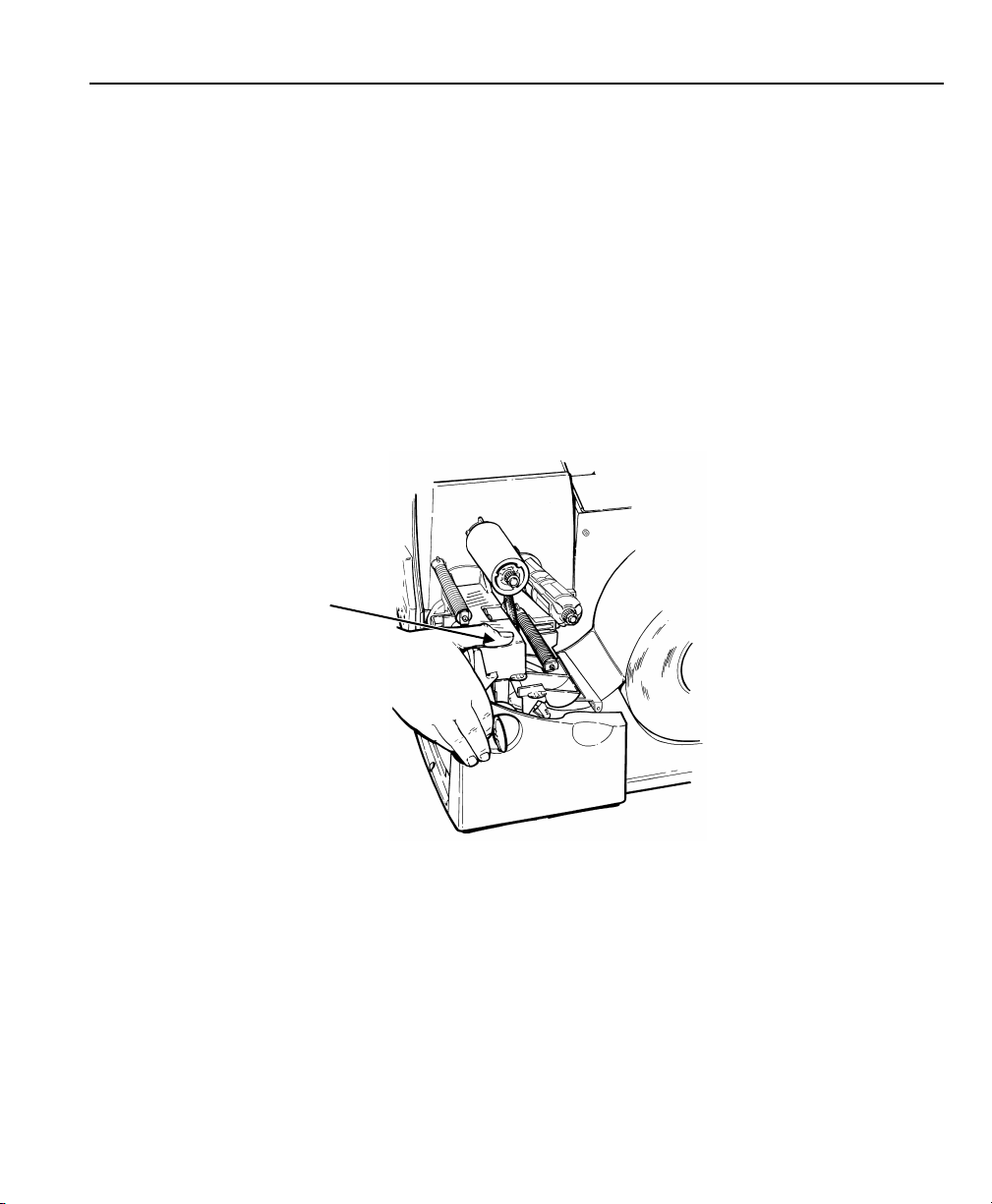
Establishing Communications
Before the printer can accept print jobs from the host, you must:
♦ Connect the communication cab le to the printer and to the host .
♦ Set the communication values o n the printer to mat ch those at the host.
(Only required if you are using the serial port.)
♦ Make sure the printer is off before connecting the cable to t he
communication port.
Ask your System Administrat or which
method to use to communicate with t he host:
Serial Communication
9 to 25-pin cable
(Part #119806)
25 to 25-pin cable
(Part #126826)
Parallel Communication
IEEE-1284 or
Centronics® mode cable (Par t #126805)
Power Cable
Connecting the C ommunication Cable
Connect the communication cab le into the
appropriate port. Secur e the cable with the connecting screws (serial) or
spring clips (parallel).
If you are communicating with t he host through the serial port , make sure the
printer's communication values match those at the host . The factory default
values are 9600 Baud, 8 bit dat a frame, 1 stop bit, no parity, and DTR flow
control.
The printer also has a USB (Uni versal Serial Bus) Version 1.1
communication port. Dri vers are available on our W eb site for a variety of
operating systems.
Note: The pr inter supports a baud rate up to 115 200. Make sure your host
is capable of communicati ng at the speed you select fo r the printer.
Getting Started 1-5
Page 14

Using the Control Panel
The control panel has a t wo-lin e LCD display, 2 status light s, and five
buttons. The control pane l displays error codes/mess ages, and allows you
to setup/configur e the printer.
Printer Sta tus Lights
Power:
The printer shows a stead y green light
when it is on.
The Power light blinks when the b attery
needs to be recharged (only on
battery-powered/cart mo dels).
Fault:
The printer shows a blinking am ber
light when there is a printer er ror.
Button Functions
Feed/Cut:
Enter/Pause:
1-6 Operator's Handbook
♦ Prints a label in the on-demand m ode.
♦ When the printer is online, f eeds a blank label if
♦ Prints a label with error info rmation that is useful to
♦ When the printer is online, cuts the supply when
♦ When the printer is off line, changes the displayed
When the printer is online, pa uses the current print job or
resumes a paused print j ob. When the printer is offline,
selects the displayed m enu item.
there is no print job.
your System Administrator if an error is displayed.
pressed and held for two second s if a knife is
installed.
value by one or 10.
Page 15

Cancel All
Print Mode
Batch Entry
Repeat
Batch
Batch
Options
Setup
Scripts
Diagnostics
Supply
Contrast
Defaults
Network
Port
Settings
Flash
Memory
Verifier
RFID
Escape/Clear:
♦ When an error is present, clears the error.
♦ When a job (batch) is printing, cancels the print job
(batch). See "Canceling a Paused B atch" in Chapter
8 for more information.
♦ When the printer is online ( without errors), enter s the
offline menu mode.
♦ When the printer is in t he of fline menu mode, returns
the display to the next hig her menu.
When the printer is in t he offline menu mode, displays th e
previous menu item.
When the printer is in t he offline menu mode, displays th e
next menu item.
AND
In online mode, prints a t est label when you press the
buttons at the same time. Hold for one second and release.
Display
The display shows a three-dig it error code and brief messag e to identify any
problem the printer may ha ve. For a description of the pr oblem, look up the
error code in Chapter 10, "Diagnostics & Troubleshoot ing."
Selecting a Function
The Main menu has several funct ions (operating modes). T hese functions
are shown in the chart belo w. See Appendix C, “Menu Structure” f or a
complete list of menu options.
Main Menu
Note: If t he printer displays PRINT MODE Ready when you turn it on,
press Escape/Clear to disp lay the Main menu.
Getting Started 1-7
Page 16

To display menu options, pr ess or .
1. When the screen displays a rig ht arrow, press to display more
options.
MAIN MENU
Cancel All
2. When the screen displays a le ft arrow, press to display more o ptions.
MAIN MENU
Diagnostics
3. When the screen displays a le ft and a right arrow, press either or
to display more options.
MAIN MENU
Print Mode
4. When you see the menu option you want, press Enter/Pause to s elect it.
The Main Menu controls the print er's setup and operation. Through the
Setup Menu, you can select a sub-menu f or the supply, contrast, default, or
port settings. Each of t hose sub-menus have several options, such as
ribbon, speed, monetary symbo ls, and baud rate.
Exiting an Option
To exit an option, press Escape/Clear once.
1-8 Operator's Handbook
Page 17

2
LOADING SUPPLIES
This chapter describ es how to load:
♦ a roll of supply
♦ fan-fold supply
♦ a roll of tag supply.
There are three types of s upplies:
Thermal Direct heat activated supplies that do not use a ribbon for
printing.
Thermal Transfer standard supplies that require a ribbon for printing.
High Energy scratch, chemical, and t emperature resistant supplies
that require an elevated heat setting for resin ribbon
applications. See "Using a High Energy Ribbon" in
Chapter 3 for more informat ion.
If you are using thermal dire ct supplies, do not load a rib bon.
If you switch from black mark to die cut supplies, make sur e the printer's
supply type is set correc tly. See "Supply Type" in Chapter 4 for more
information. Your System Administrator can also send the s upply setup
packet to change the supply t ype. Refer to the optional Pack et Reference
Manual for more inf ormation about sending the suppl y setup packet.
Loading Supplies 2-1
Page 18
Loading Labels or Tags
Printhead Tab
Make sure the printer is conf igured for the correct supply t ype.
1. Open the cover.
2. Unlock the printhead by tur ning the retaining latch .
3. Lift printhead assemb ly using the printhead tab unt il t he assembly locks
into place.
2-2 Operator's Handbook
Deflector Tab
Page 19
4. Place the roll of supply on the sup ply holder. For labels, t he supply
unrolls from the top or t he bottom. For tags, make sure t he supply
unrolls from the botto m, because tag rolls are wound fa ce in.
Note: Do not pick up the printer by the supply hol der.
Supply Holder
Guides
Supply Roller
5. Adjust the supply holder g uides so the sides barely touch the ro ll. Make
sure the supply roll turns freely.
If you are using fan-fold supplies , place the supply stack behind
the printer, label side facing up.
6. Push down on the supply lever to u nlock the supply guides.
7. Lay the label strip across t he supply guide so that a few inches extend
past the front of the printer . Tuck the supply under the nibs an d in
between the die cut sensor. Do not feed supply between the suppl y
roller and deflector.
Loading Supplies 2-3
Page 20
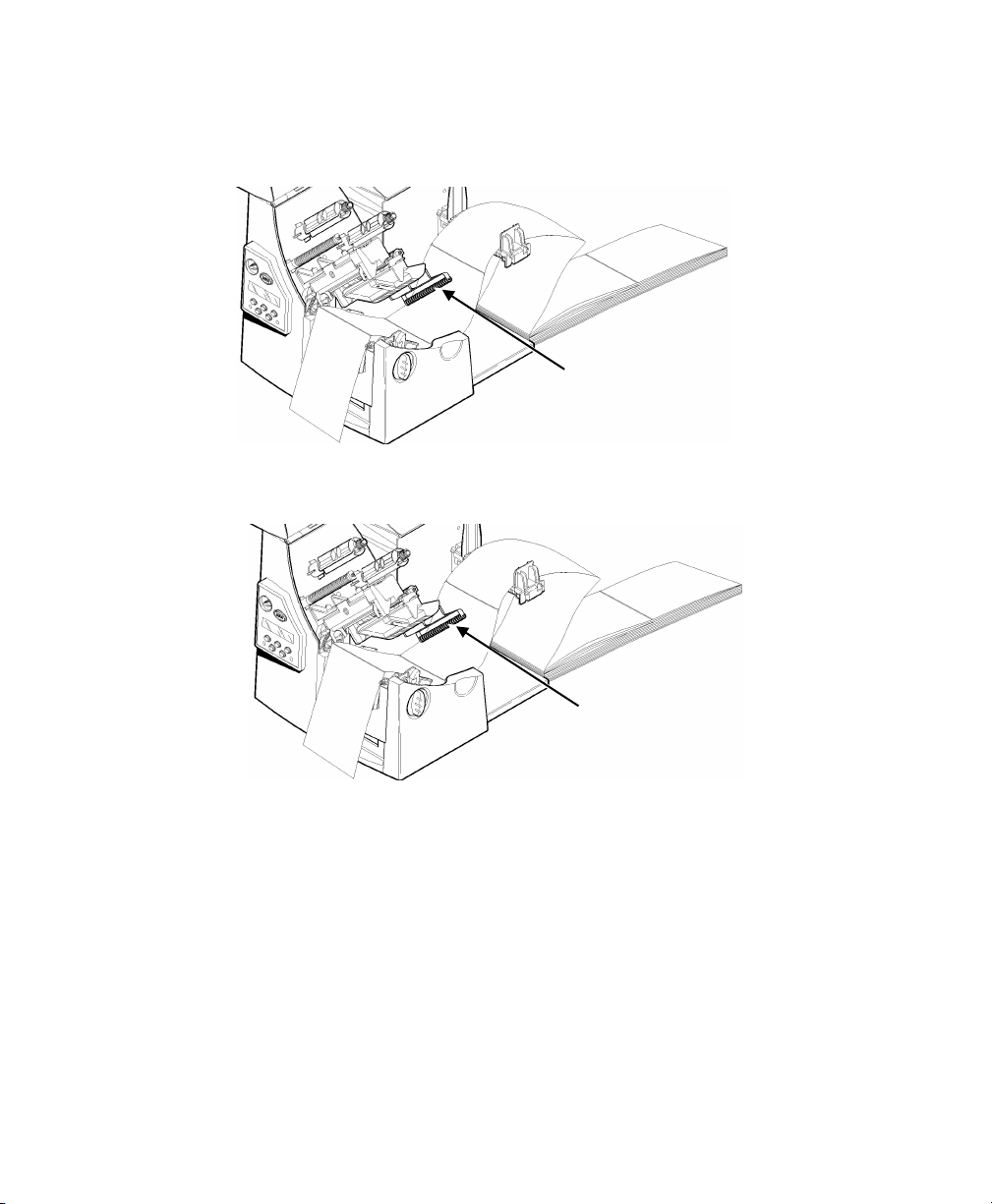
For fan-fold supplies, la y the label strip over the supply hold er and
across the supply guide so that a few inches extend past the f ront of
the printer. Tuck the supply und er the nibs and in between the d ie
cut sensor.
Supply Roller
2-4 Operator's Handbook
Supply Roller
Page 21
Sensor
For tag supplies using the opti onal knife, feed the supply thr ough
the knife. Make sure at least 0. 5 inches of supply is past the k nife.
Tag
8. Adjust the supply guides so the y touch the supply. Push up on the
supply lever to lock the supp ly guides into place.
Die Cut
Nibs
Supply Lever
Loading Supplies 2-5
Page 22

9. Hold the printhead assem bly by the printhead tab while pr essing down on
the printhead release .
10. Close the printhead by press ing down on the thumb well until you hear it
click into p lace.
Thumb Well
11. Close the cover.
12. Press Feed/Cut to position the supp ly under the printhead.
You may need to adjust the wide/na rrow knobs depending on the widt h of
your supply. See "Adjusting the Wide/Narrow Knobs" for more
information.
Note: If t he printer will be unused for extended p eriods of time, we
recommend leaving the print head unlatched.
2-6 Operator's Handbook
Page 23
Exit Cover
Loading Labels for the Optional Peel Mode
Peel mode is an option that must be purchased separatel y. In peel mode,
the printer separates t he backing paper from the label. T he next label is not
printed until the complet ed one is removed from the printer. Make sure the
printer is configured f or on-demand mode and the correct supply type.
The minimum feed lengt h is 1.5 inches for peel mode. We recom mend using
0.5-inch gap supplies in pee l mode when backfeed is disabled. Hold the
leading edge of peeled labe ls when printing on stock longer than six inches.
You must use non-perforate d supplies for peel mode. Follow th e steps for
loading supplies from the previous section. T hen, follow these steps afte r
you close the printhead.
1. Remove the labels from t he first 10 inches of the backing pa per.
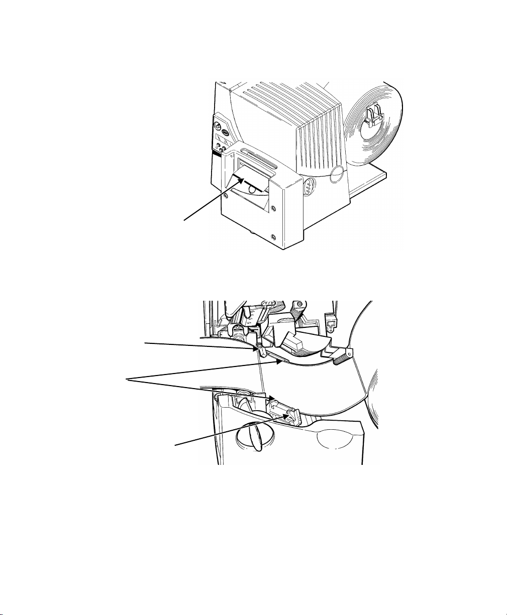
2. Press down on the exit cover t abs to open the exit cover on the f ront of
the printer.
Loading Supplies 2-7
Page 24
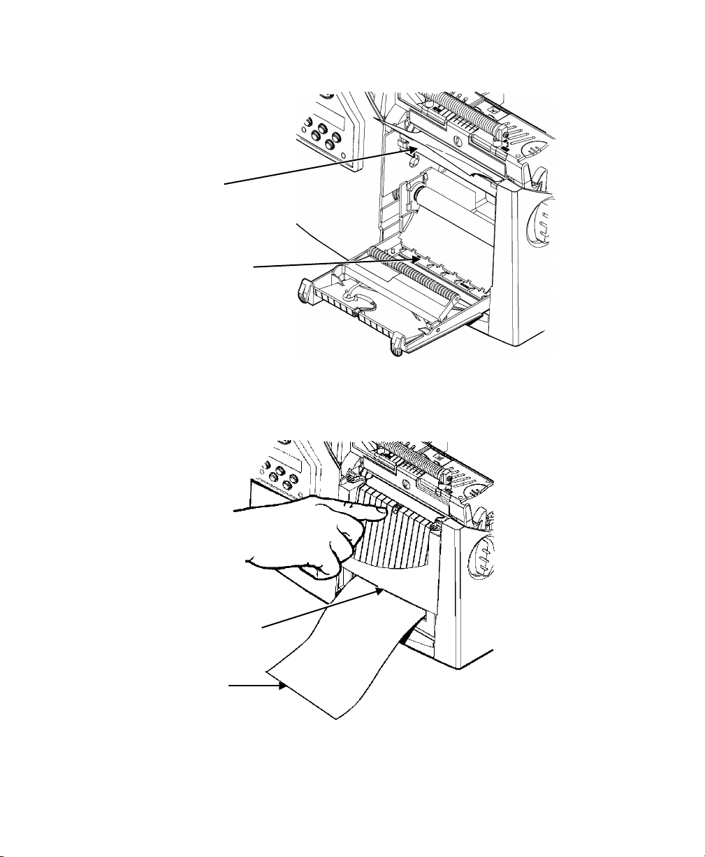
3. Feed the backing paper over t he peel bar.
Peel Bar
Lower Opening
4. Feed the backing paper t hrough the lower opening of t he exit cover.
Close the exit cover. Pul l down on the backing paper to remove any
slack.
Tear Edge
Backing Paper
When removing the backing paper , pull up across the sawtoothed tear edge. Make sur e the backing paper tears at t he edge.
2-8 Operator's Handbook
Page 25

5. Close the printer's cover.
6. Press Feed/Cut to position the supp ly under the printhead.
Using the Optional Tear Bar
Note the following chang e to loading labels if you have purcha sed the
optional tear bar. Tear labe ls against the tear bar. You cannot t ear tags
with the tear bar.
Slide the supply between t he tear bar and peel bar. It may be easier if you
cut or fold one corner of t he supply first.
Tear Bar
Peel Bar
Note: Do not tea r both label and backing paper at the same time.
♦ Tear labels against the t ear bar.
♦ Tear backing paper against the tear edge.
Tear Edge
Backing Paper
Loading Supplies 2-9
Page 26

Using String Tag Supply
String tags are used in a variet y of applications, such as je welry tags and
item marking.
String Tag Consi derations
♦ Thermal direct printin g, fan-fold supplies, and the k nife are not supported
with string t ags.
♦ The maximum print speed wit h s tring tags is 6.0 inches per sec ond (ips).
♦ A non-print zone of 0.250 inches (6.4 mm) exists on the string si de of the
tag.
♦ Use the wide setting for st ring tags.
Make sure the printer is conf igured for the correct suppl y type.
1. Open the cover.
2. Unlock the printhead by turning the retaining latch.
3. Lift printhead assembly using the printhead tab until the assembly locks
into place.
4. Shake the roll of string tags down to untangle the roll.
2-10 Operator's Handbook
Page 27

Sensor
5. Place the roll of supply on the supply holder with the strings facing out.
6. Adjust the supply holder guides so the sides barely touch th e roll. Make
sure the supply roll turns freely.
7. Push down on the supply lever to unlock the supply guides. T he supply
guides have been angled slig htly for string tag supplies.
8. Lay the supply across the supply guide so that a f ew inches extend past
the front of the printer . Tuck the supply under the nibs and in be tween
the die cut sensor.
9. Adjust the supply guides so they touch the supply. Push up on t he supply
lever to lock the suppl y guides into place.
Die Cut
Nib
Supply Lever
Loading Supplies 2-11
Page 28
10. Hold the printhead assembl y by the printhead tab while press ing down on
the printhead release .
11. Close the printhead b y pressing down on the thumb wel l until you hear it
click into p lace.
12. Close the cover.
13. Press Feed/Cut to posit ion the supply under the print head.
If the printer will be unused f or extended periods of tim e, we recommend
leaving the printhead unlat ched.
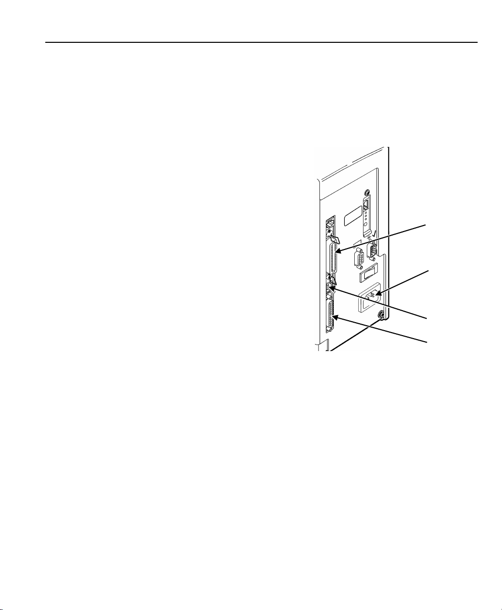
Adjusting the Wide/Narrow Knobs
You may need to adjust the t wo wide/narrow knobs according t o the width of
your supply. For supply that is mor e than two inches, adjust the k nobs to
the wide setting. For supply that is two inches or less, adjust t he knobs to
the narrow setting. For s tring tag supply, use the wide set ting (knobs are
down).
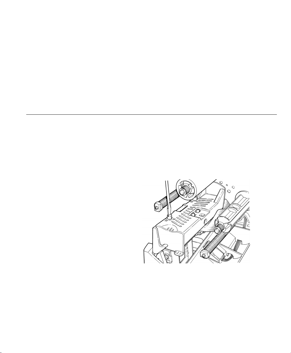
You must adjust both of the k nobs to the same position.
If you experience ribbon
smudging in cold, dry
environments, adjust t he
wide/narrow knobs to the
wide setting .
For wide supplies, push
down and turn the
wide/narrow knobs
clockwise with a
screwdriver.
For narrow supplies, tur n the wide/narrow knobs counter-c lockwise wit h a
screwdriver until it po ps back up.
Note: The adj ustment is shown in the wide pos ition.
2-12 Operator's Handbook
Page 29

3
LOADING RIBBON
This chapter describes how to load a ribbon roll.
There are different ribbon requirements for the thr ee types of supplies:
Thermal Direct do not use a ribbon for printing .
Supplies
Thermal Transfer require a ribbon for pr inting.
Supplies
High Energy require a ribbon able to wit hstand high temperatures .
Supplies
If you are using thermal direc t supplies, do not load a rib bon.
If you are using high energ y supply, be sure to use a high energ y ribbon.
See "Using a Hig h Energy Ribbon" for more information. To set ribbon
options at the printer, s ee "Ribbon" in Chapter 4.
Loading Ribbon 3-1
Page 30
Loading Ribbon
Make sure the printer is conf igured to use a ribbon.
To load ribbon:
1. Open the cover.
2. Unlock the printhead by tur ning the retaining latch .
3. Lift printhead assemb ly using the printhead tab unt il the assembly locks
into place.
Printhead
Assembly
Deflector
Tab
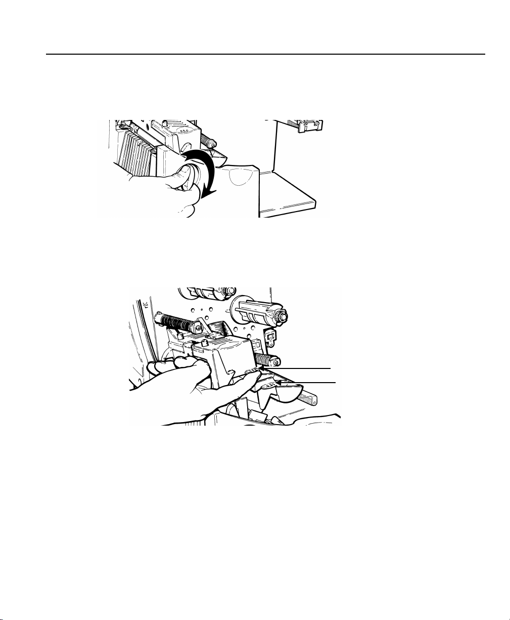
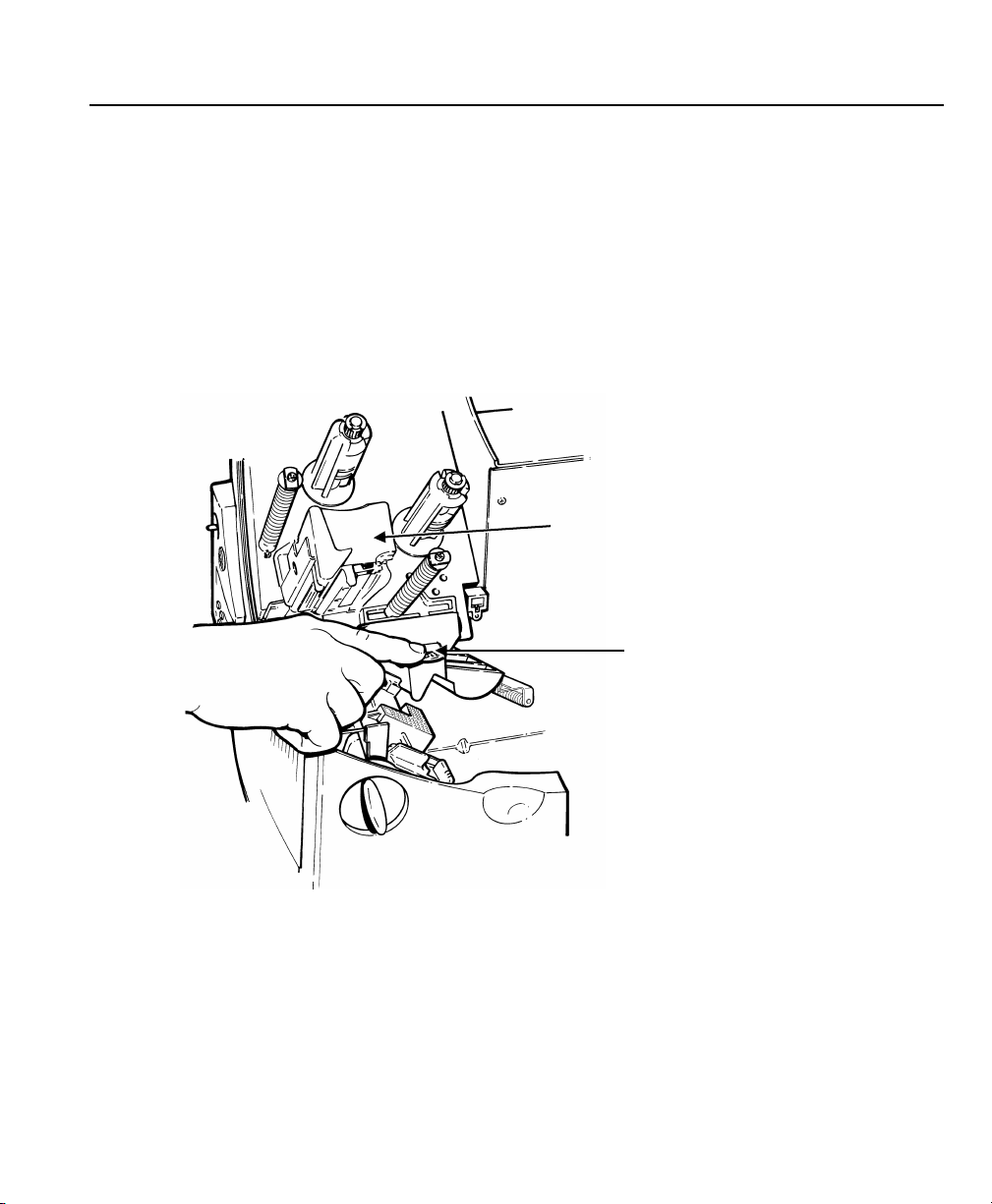
4. Push the deflector tab do wn.
5. Slide the extra ribbon cor e on the take-up reel as far as it will g o with the
"This End Out" writing facing out. Use your empty ribbon cor e as the
take-up core. The take-up core onl y fits on the take-up reel one way.
(An extra take-up core is availa ble by ordering part number 117961.)
3-2 Operator's Handbook
Page 31

Take-up Core
Take-up Reel
Ribbon Rollers
6. Remove the new ribbon fr om the package as shown. Do not wrinkle or
crush the new ribbon.
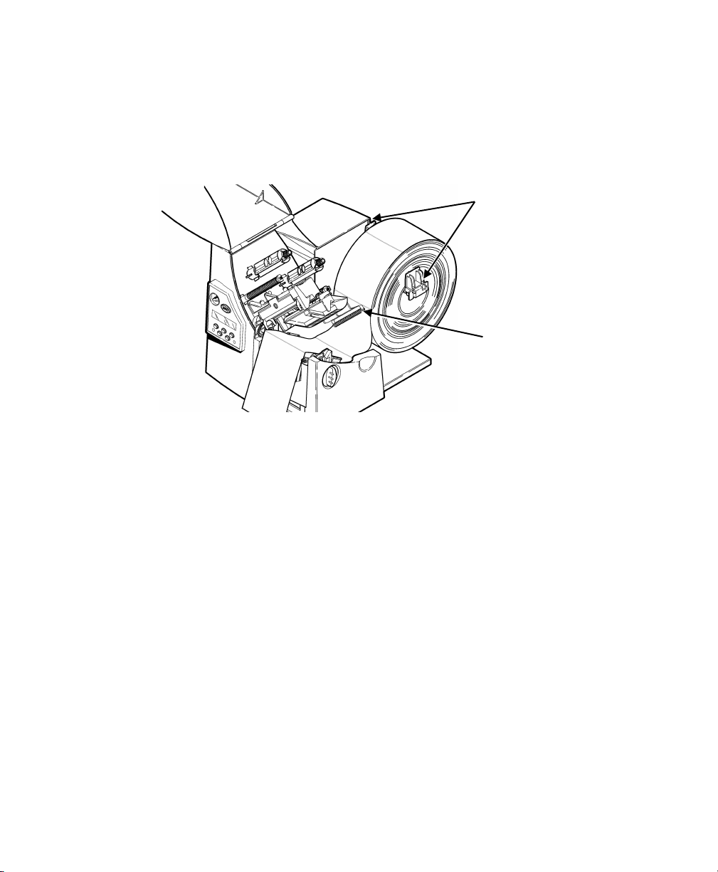
7. Slide the ribbon onto the bac k reel as far as it will go. T he ribbon roll
only fits on the reel one way. Carefully unwind a few inches of ribbon
from the bottom of the roll.
Note: Mak e sure the “Monarch This End Out” writing is facing out.
The ribbon only fits on the ree l one way.
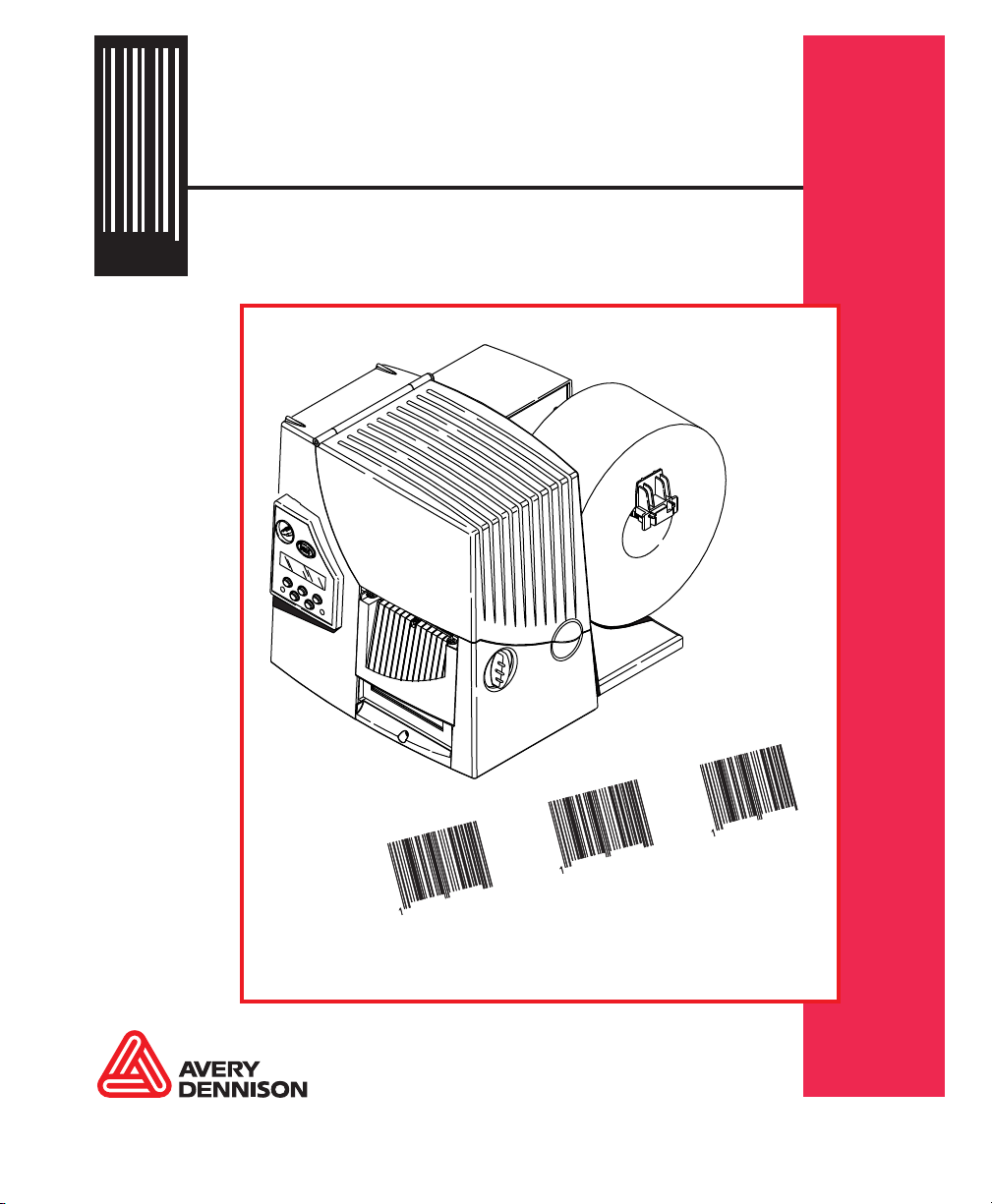
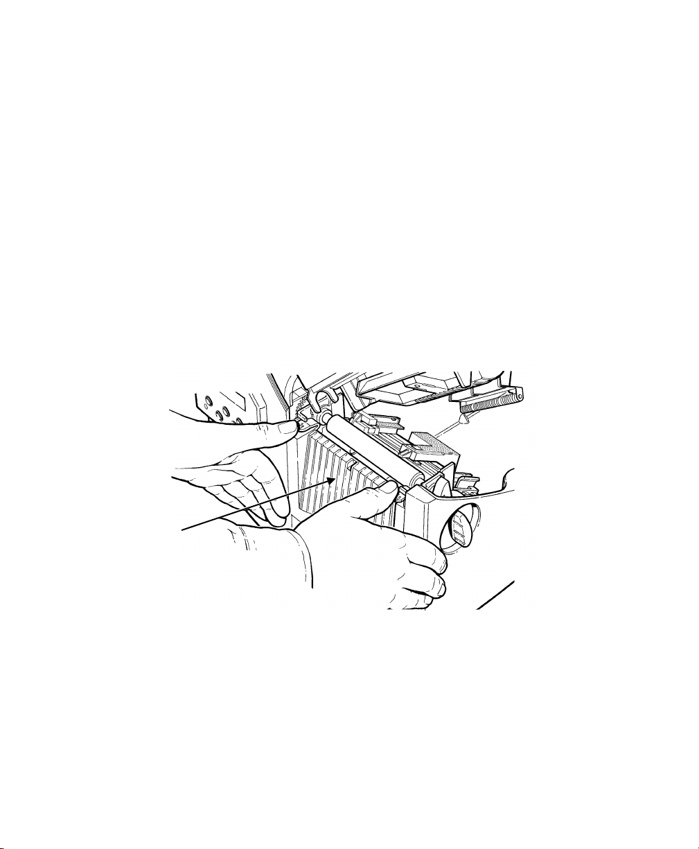
8. Carefully feed the ribbon under both ribbon rollers and pr inthead as
shown.
9. Align the ribbon and mak e sure it is straight and centered thr oughout the
path.
10. Tape the ribbon to the tak e-up core. Do not tape the ribbon to the
take-up reel.
11. Rotate the take-up core until t he leader is past the printhead.
Loading Ribbon 3-3
Page 32

12. Remove any slack in the ribbon b y turning the take-up reel clock wise.
13. Hold the printhead assem bly by the printhead tab while pr essing down on
the printhead release .
14. Close the printhead by press ing down on the thumb well unti l you hear it
click into place. Close t he cover.
Thumb Well
Using a High Energy Ribbon
High energy ribbon is an option for this printer. It enables you to print on
high energy (TUFF-MARK®) suppl ies.
When you select high energ y ribbon for the printer sett ing, you are setting
the printer to a higher print ing temperature. Select this s etting only after you
have loaded a high energy ribbo n and supply or it may damage your
printhead. See "Ribbon" in Chapter 4 for mor e information.
3-4 Operator's Handbook
Page 33

High Energy Ribb on Limitations
When using the high energy ribb on option:
♦ Use a print speed of 2.5IPS (inch es per second).
♦ Printhead warranty is redu ced to 100,000 inches.
♦ Serial bar codes cannot be pr inted.
♦ Do not use peel mode.
♦ No more than 20% of the supply shou ld have print (black coverag e).
CAUTION: The high energy ribbon may break or stick to the supply when
more than 20% of the supply conta ins print.
♦ Only white high energy suppl y should be used for bar code p rinting.
♦ Reverse fonts cannot be used.
♦ A non-printing area of at least .1 inch (2.54 mm) must exist on the lef t
and right edge of the ribbon.
♦ Do not print horizontal l ines or bars.
♦ Graphics are limited.
Loading Ribbon 3-5
Page 34

3-6 Operator's Handbook
Page 35

Cancel All
Print Mode
Batch
Entry
Repeat
Batch
Batch
Options
Setup
Scripts
Diagnostics
Supply Contrast
Defaults
Network
Port
Settings
Flash
Memory
Verifier RFID
Type
Index
Ctrl
Action
4
SETTING SUPPLY OPTIONS
This chapter explains how to select the supply type, ribb on, speed,
feed mode, backfeed, pr int position, supply positio n, margin position, cut
position, dispense po sition, backfeed dista nce, separators, skip index mode,
set knife control, and set error action.
This chapter also explai ns how to adjust the print contr ast and enable the
verifier.
Main Menu
Supply
Ribbon Speed Feed Mode Backfeed Positioning Separators Skip
Knife
Error
Your System Administrat or may limit access to this menu to pr event supply,
network, script, or communication settings from being changed. If password
protection is turned o n, you see
Enter Passwor d
_ _ _ _ _ _
when you try to access the set up menu. Get the password from your System
Administrator to conti nue.
Setting Supply Options 4-1
Page 36

The options are listed in the t able below.
Option
Choices
Default
Supply Type Aperture/D ie Cut/Black
Mark/Continuous
Ribbon No/Yes/Hig h Energy Yes
Speed 2.5/4.0/6.0/8.0/10.0/12.0/Default Default
Feed Mode Continuous/On-Demand Continuous
Backfeed Off/On/Extended Off
Print Posi tion -450 to 450 0
Supply Posit ion -300 to 300 0
Margin Pos ition -99 to 99 0
Cut Position -300 to 300 0
Dispense
Position
Backfeed
Distance
Separators No/Yes/Long No
Skip Index No/Yes No
Knife Control -20 to 20 0
Error Actio n Normal
Contrast -699 to 699 0
50 to 200 65
10 to 200 65
Overstrik e/Continue x1
Overstrik e/Continue x2
Overstrik e/Continue x3
Overstrik e/Continue x4
Overstrik e/Continue x5
Die Cut
Normal
To exit an option without c hanging the setting, pr ess Escape/Clear.
4-2 Operator's Handbook
Page 37

Setting the Supply Type
You can print on aperture, black mark, die cut, or continuous su pplies. You
have to tell the printer which supplies you are using.
Note: If you are us ing edge aperture supplies , use the die cut setting. If
you are using center aperture sup plies, use the aperture set ting.
To change the setting, f rom the Main Menu, select Setup, then S upply. If
password protection i n enabled, press Feed/Cut three times, then press
Enter/Pause before you s ee the Setup Menu options. Then, follow these
steps.
1. Press or until you see
SUPPLY
Supply Type
2. Press Enter/Pause to set the s upply type option. The current setting is
displayed, for example:
SUPPLY T YPE
Black Mark
3. Press or to see the other options. After you disp lay the option you
want, press Enter/Pause. Press Escape/Clear until you see the Main
Menu.
Setting Supply Options 4-3
Page 38

Setting the Ribbon
You have to tell the printer if your supplies require a ribbon. To change the
setting, from the Main Menu, s elect Setup, then Supply. Then, follow these
steps.
1. Press or until you see
SUPPLY Ribbon
2. Press Enter/Pause to set t he ribbon option. The current s etting is
displayed, for exampl e:
RIBBON
Yes
3. Press or to see the other options. After you disp lay the option you
want, press Enter/Pause. Press Escape/Clear until you see the Main
Menu.
Note: If you set the Ribbon option to Yes, instal l a ribbon before printing .
If you want to use a high energ y ribbon, select high energy f or the
ribbon.
4-4 Operator's Handbook
Page 39

Setting the Speed
You can change the print speed f or bar codes or graphics. If you select
"default" for speed, formats with serial bar codes automat ically print at 2.5
ips and formats with paral lel bar codes print at 6.0 ips. 12. 0 ips printing is
an option that must be purchased se parately.
Note: If you chang e the speed, you must resend your formats or turn the
printer off and back on before the change takes eff ect.
To change the setting, f rom the Main Menu, select Setup, then S upply.
Then, follow these steps.
1. Press or until you see
SUPPLY
Speed
2. Press Enter/Pause to set t he speed option. The current sett ing is
displayed, for exampl e:
SPEED
Default
3. Press or to see the other options. After you disp lay the option you
want, press Enter/Pause. Press Escape/Clear until you see the Main
Menu.
Note: For addit ional high speed printing information, see Chapter 8,
"Printing."
Setting Supply Options 4-5
Page 40

Setting the Feed Mode
You can use continuous or on-dem and printing. On-demand print ing allows
you to remove a label bef ore printing the next one.
To change the setting, f rom the Main Menu, select Setup, then S upply.
Then, follow these steps.
1. Press or until you see
SUPPLY
Feed Mode
2. Press Enter/Pause to set t he feed mode. The current setting is
displayed, for exampl e:
FEED MODE
Continuous
3. Press or to see the other option. After you disp lay the option you
want, press Enter/Pause. Press Escape/Clear until you see the Main
Menu.
4-6 Operator's Handbook
Page 41

Setting the Backfeed
Backfeed works by advancing ea ch printed label to the desir ed dispense
position. Once that label is removed, the next label to be print ed is backed
up underneath the printhe ad. In continuous mode, onl y the last label in the
batch is advanced to the dispe nse position. Extended back feed is available
on this printer with a k nife installed. Extended backf eed feeds a tag far
enough out to be cut and backf eeds the next tag to the print head line.
Extended backfeed eliminat es printed tags being lef t between the printhead
and knife. Extended backf eed works with the selected cut modes. Refer to
the optional Packet Ref erence Manual to learn how to def ine the Backfeed
Control Packet. Extended back feed does not work with non-indexed
(continuous) supply/m ode. Do not use backfeed (norm al or extended) with
supplies less than 0.75 inches.
Note: W e recommend using 0.5-inch gap supplies in pee l mode when
backfeed is disabled.
To change the setting, f rom the Main Menu, select Setup, then S upply.
Then, follow these steps.
1. Press or until you see
SUPPLY
Backfeed
2. Press Enter/Pause to set t he backfeed option. The current setting is
displayed, for exampl e:
BACKFEED
On
3. Press or to see the other options. After you disp lay the option you
want, press Enter/Pause. Press Escape/Clear until you see the Main
Menu.
Setting Supply Options 4-7
Page 42

Changing the Position Settings
This menu includes select ions to change the print, supp ly, margin, cut, and
dispense positions along with the backfeed distance.
When you see
Enter print pos
[-450/450]: +0
Feed/Cut acts as a toggle s witch to change the value by 10 or 1. For
example, to make the print posit ion 23 (from the default of 0), press
Feed/Cut, then press twice (20) , press Feed/Cut again and pr ess three
times (23).
Setting the Pri nt Position
This function adjusts wher e data prints verticall y on the supply. Adjust the
print if it is too close to t he top or bottom of the supply, or o vertypes the preprinted area. One dot is 0. 0049 inch.
♦ If the data is too close to t he bottom, increase the number.
♦ If the data is too close to t he top, decrease the number.
Note: Changing this setting only aff ects new formats sent to the printer.
4-8 Operator's Handbook
Page 43

To change the setting, f rom the Main Menu, select Setup, Suppl y, then
Positioning. T hen, follow these steps.
1. Press or until you see
POSITIONING
Print Pos
2. Press Enter/Pause. T he current setting is displa yed, for example:
Enter print pos
[-450/450]: +0
3. Press or to change the print position. Pressing decreases the
value (moves the image down); incre ases it (moves the image up) .
4. Press Enter/Pause when the number you need appe ars. Press
Escape/Clear until you see the Main Menu.
Setting Supply Options 4-9
Page 44

Setting the Supply Positi on
This function adjusts t he machine to print at the vertica l 0,0 point on the
supply.
Note: The su pply position adjustment should only be made on initial
printer setup. For f ormat adjustments, change the pr int position.
You may need to adjust the suppl y in or out to allow
♦ tags and labels to be removed.
♦ die cut labels to be removed easi ly.
The adjustments are in dots (0.0049 inch).
♦ Increase the number to f eed more supply out of the chute.
♦ Decrease the number to feed les s supply out of the chute.
This option takes eff ect on the next label or tag print ed. Changing supply
position may also affect print position.
To change the setting, f rom the Main Menu, select Setup, Suppl y, then
Positioning. T hen, follow these steps.
1. Press or until you see
POSITIONING
Supply Pos
2. Press Enter/Pause. T he current setting is displa yed, for example:
Enter supply pos
[-300/300]: +0
3. Press or to change the suppl y position. Pressing decreases the
value (feeds less supply); incr eases it (feeds more suppl y).
4. Press Enter/Pause when the number you need appears. Press
Escape/Clear until you see the Main Menu.
4-10 Operator's Handbook
Page 45

Setting the Margin Positi on
This function adjusts wher e the format prints horizont ally on the supply. The
adjustments are in dots (0.0049 inch), which is the small est measurement
the printer recognizes.
The width of the print ar ea depends on your supply size. Maximum width is
four inches. When you move the imag e to the right or left on t he supply,
avoid moving the image t oo close to either edge, because it may not print.
Print too far to the l eft. Print too far to the ri ght.
♦ If the data is too clos e to the left side, increase t he number.
♦ If the data is too close to t he right side, decrease the number .
Note: Changing this setting only aff ects new formats sent to the printer.
To change the setting, f rom the Main Menu, select Setup, Suppl y, then
Positioning. Then, follow these steps.
4. Press or until you see
POSITIONING
Margin Pos
5. Press Enter/Pause. The curr ent setting is displayed, f or example:
Enter margi n pos
[-99/99]: +0
6. Press or to change the margin position. Pressing decreases the
value (moves the image to ward the left side of the supply); increases
it (moves the image toward the r ight side of the supply).
7. Press Enter/Pause when the number you need appears. Press
Escape/Clear until you see the Main Menu.
Setting Supply Options 4-11
Page 46

Setting the Cut Pos ition
This function adjusts wher e the tag is cut. The printer adj usts the cut
position according to t he black marks on the supply. You ma y need to adjust
for aperture supplies. Increase to move the cut up; decrease t o move the
cut down.
To change the setting, f rom the Main Menu, select Setup, Suppl y, then
Positioning. Then, follow these steps.
1. Press or until you see
POSITIONING
Cut Pos
2. Press Enter/Pause. The curr ent setting is displayed, f or example:
Enter knife adj
[-300/300]: +0
3. Press or to change the cut position. Press ing decreases the
value (moves the cut down); incr eases it (moves the cut up).
Note: W e do not recommend setting a positive cu t position while using
extended backfeed. You may cut off the leading edge of t he next
tag.
4. Press Enter/Pause when the number you need appears. Press
Escape/Clear until you see the Main Menu.
4-12 Operator's Handbook
Page 47

Setting the Dispense Posi tion
This function adjusts t he stopping point of the label.
To change the setting, f rom the Main Menu, select Setup, Suppl y, then
Positioning. Follow these s teps.
1. Press or until you see
POSITIONING
Dispense Pos
2. Press Enter/Pause.
DISPENSE POS
[50/200]: + 65
3. Press or to change the dispense posit ion. Pressing decreases
the value; increases it.
4. Press Enter/Pause when the number you need appears. Press
Escape/Clear until you see t he Main menu.
Setting Supply Options 4-13
Page 48

Setting the Backfeed Distance
This is the amount to move the labe l backwards. The backf eed distance
cannot be greater than t he dispense position. If you mak e the backfeed
distance greater than the dispense position, the disp ense position
automatically changes t o match the backfeed distance.
The backfeed distance should eq ual the dispense position. An exc eption is
when you are tearing labels, instead of peeling. Then, the backfeed distance
must be 30 dots (0.15 inches) l ess than the dispense position t o account for
improper tearing of butt cut supplies. You will have a 30-dot non-pr int zone
on your supply, but this pre vents exposed adhesive under the pr inthead.
To change the setting, f rom the Main Menu, select Setup, Suppl y, then
Positioning. Follow these s teps.
1. Press or until you see
POSITIONING
Backfeed D is
2. Press Enter/Pause.
BACKFEED DIS
[10/200]: + 65
3. Press or to change the dispense posit ion. Pressing decreases
the value; increases it.
4. Press Enter/Pause when the number you need appears.
Press Escape/Clear until you see t he Main menu.
4-14 Operator's Handbook
Page 49

Using Batch Separators
A batch separator is an extra t ag printed in between batches with a pinstripe
pattern. If you select " Long" for the separator, a double-len gth (two tags)
separator prints. For non-in dexed supply, the batch separat or is always six
inches long. If you have the Monarch® 928™ stacker installed, the batch
separator is 3.66 inches long . The name of the batch is shown on t he batch
separator.
Batch Separator
Note: Changing this setting only aff ects new formats sent to the printer.
To change the setting, f rom the Main Menu, select Setup, then S upply.
Then, follow
these steps.
1. Press or until you see
SUPPLY
Separators
2. Press Enter/Pause to set t he batch separators option. The cur rent
setting is displayed, f or example:
SEPARATORS
No
3. Press or to see the other options. After you disp lay the option you
want, press Enter/Pause. Press Escape/Clear until you see the Main
Menu.
Setting Supply Options 4-15
Page 50

Using Skip Index
You can use the skip index mode to sk ip (or ignore) a sense mar k and print
an image over multiple labe ls, if necessary. For example, if you have 4.0"
long supplies loaded, but your image is 8.0" long, enable s kip index mode to
print the 8.0" long imag e on two labels. The image length is de termined by
the format header. See your System Administrator or the option al Packet
Reference Manual for more information. The skip index feat ure is useful
when you have a single f ormat that contains two labels, such a s a shelf
label and a carton label.
Note: W hen designing the format, make sur e text or graphics do not print
in the gap of label rolls.
To change the setting, f rom the Main menu, select Setup, then S upply.
1. Press or until you see
SUPPLY
Skip Index
2. Press Enter/Pause to set t he skip index mode. You will see the cur rent
setting, for example:
SKIP INDEX
No
3. Press or to see the other options. After you disp lay the option you
want, press Enter/Pause. Press Escape/Clear until you see the Main
Menu.
4-16 Operator's Handbook
Page 51

Setting the Knife Control
You may notice unevenly cut ta gs on one end or the other of your supp ly
(one end may appear longer t han the other). Use the knife con trol
adjustment to balance t he cut tag length from tag-to-tag.
You may need to make this adjust ment
♦ on initial printer setup .
♦ if you load a differ ent supply type (thickness) f rom the last ones printed.
♦ when you change the print speed.
♦ when you change to a diffe rent tag size from the last ones printe d.
To change the setting, f rom the Main Menu, select Setup, then S upply.
Then, follow these st eps.
1. Press or until you see
SUPPLY
Knife Ctrl
2. Press Enter/Pause. T he current setting is displa yed, for example:
Enter knife ctrl
[-20/20]: +0
3. Press or to change the knif e control. You may need to experiment
and cut a few test tags to check the tag cut length. Pressing
decreases the value; increases it .
Note: Depending on how unevenly the tags are c ut, always start with a
small number, such as +- 1 or 2.
4. Press Enter/Pause when the number you need appears.
Press Escape/Clear until you see the Main Menu.
Setting Supply Options 4-17
Page 52

Setting the Error Action
Error Action
Standard
Peel
Verifier
with Peel
RFID wit h
Peel
Overstrike/Continue 1 -5
No
No
No
Normal (no overstrike)
Yes
Yes
Yes
The recovery action from an e rror condition is in the Setup, Sup ply Menu.
You can change how the printer res ponds to a bad scan. The choices
include normal and overstrik e/continue one to five consec utive bad scans.
The overstrike pattern is created to prevent someone f rom using a bad label.
Selecting overstrik e and continue 1x-5x sets the number of times the printer
prints an overstrike patt ern on consecutively bad labe ls before generating an
error. The user must clear the er ror before operation ca n continue.
Do not use the overstrike action w ith
♦ Peel mode
♦ String tag supplies
For more information about the error actions, see t he following table.
Consider this scenario w hen the error action is set to overst rike/continue 3x:
If the printer errors on the first label, an overstrik e pattern is printed, but the
printer attempts to r eprint the image up to three times. If the third
consecutive label also g enerates an error, an overstrike pat tern is printed;
however, the printer st ops and the error message is displa yed. The operator
must resolve the error condit ion before printing continues.
In the above example, if the third label did NOT generate an er ror,
♦ the batch image is printed
♦ the consecutive error count er is reset
♦ the printer continues pr ocessing the batch.
4-18 Operator's Handbook
Page 53

Normal (default)
The printer errors and t he condition causing
the error is displayed. T he error must be
cleared before operat ion can continue. An
operator must press Escape/Clear to clear the
error and continue print ing. No overstrike
pattern is printed.
Overstrike/Continue 1x
Overstrike/Continue 2x
Overstrike/Continue 3x
Overstrike/Continue 4x
Overstrike/Continue 5x
The printer prints an overst rike pattern on one,
two, three, four, or five consecutive labels and
stops printing afte r the selected number of
overstrike patterns ha ve been printed. An
operator must press Escape/Clear to clear the
error and continue print ing. Do not use the
label with the overstri ke pattern.
Note: The printer re-calibrat es (feeds a blank
label) after a motion or verif ier error.
To change the setting, f rom the Main Menu, select Setup, then S upply. Then
follow these steps.
1. Press or until you see
SUPPLY
Error Act ion
2. Press Enter/Pause. T he current setting is displa yed, for example:
ERROR ACTION
Ostrk/Cont 1x
3. Press or to see the other options. Af ter you display the option you
want, press Enter/Pause.
4. Press Escape/Clear until you see the Main Menu.
Note: Depending on the selected error action, you may or may not see a
label with the overstri ke pattern.
Setting Supply Options 4-19
Page 54

Setting the Print Contrast
Cancel All
Print Mode
Batch Entry
Repeat
Batch
Batch
Options
Setup
Scripts
Diagnostics
Supply
Contrast
Defaults
Network
Port
Settings
Flash
Memory
Verifier
RFID
The print contrast cont rols the darkness of the printing on your supply. The
range is -699 to +699 and the def ault is 0. Having the correct print contrast
setting is important becaus e it affects how well your bar code s scan and how
long your printhead last s. You can use a verifier to check the bar code print
quality.
Main Menu
High contrast setting s may
♦ require additional pri nthead cleaning.
♦ create bar code growth, lead ing to reduced scanning.
CAUTION: Setting the print contrast higher than 399 reduces the print head
warranty to 100,000 inches and m ay damage the printhead.
1. From the Main Menu, press or until you see
MAIN MENU
Setup
2. Press Enter/Pause. You will be at the Setup menu. Press or until
you see
SETUP
Contrast
3. Press Enter/Pause. The current setting is displayed, for example:
Enter contr ast
[-699/+699]: +0
4. Press or to change the contrast. Pressing darkens the print;
lightens the print.
4-20 Operator's Handbook
Page 55

Feed/Cut acts as a toggle s witch to change the value by 10 or 1.
For example, to make the cont rast 50 (from the default of 0), press
Feed/Cut, then press five times (50 ).
5. Press Enter/Pause to select either "Yes" or "No" to print a test label and
check the print contrast . Press Enter/Pause.
6. Press Escape/Clear until you see the Main Menu.
We recommend you check the bar code print quality with a bar code verifier.
If you do not have a bar code verif ier or scanner, check the bar code
visually. A bar code that is in spe c has complete bars, clear sp aces, and
small alphanumeric charac ters look complete. An in spec bar code may not
look as good as one that is too dark , but it has the highest scan rate.
Dark IN SPEC Light
Setting Supply Options 4-21
Page 56

Enabling the Verifier
The verifier scans and check s the quality of bar codes as they ar e printed.
The optional verifier m ust be purchased separately. T he verifier scans
parallel bar codes; it c annot scan serial bar codes.
The verifier must be enabled and s et up before you can scan bar codes.
For additional set up procedures, refer to your verifier's Operating
Instructions.
To enable the verifier, from the Main Menu, select Setup, t hen Verifier.
Then follow these steps.
1. Press or until you see
VERIFIER
State
2. Press Enter/Pause. The current setting is displayed, for example:
VERIFIER
Disabled
3. Press or to see the other option. Af ter you display the option you
want, press Enter/Pause. Press Escape/Clear until you see the Main
Menu.
4-22 Operator's Handbook
Page 57

Cancel All
Print Mode
Batch Entry
Repeat
Batch
Batch
Options
Setup
Scripts
Diagnostics
Supply
Contrast
Defaults
Network
Port
Settings
Flash
Memory
Verifier
RFID
Serial
Comm
Parallel
Comm
5
SETTING COMMUNICATIONS
This chapter tells you ho w to set the serial or parallel
communication values. These values provide the link f or normal online
printing.
Main Menu
You need to set your Serial Comm v alues to match your computer' s online
communications. Before ente ring the communication value s, see your
System Administrator.
The serial communication values are listed in the table b elow.
Option Choices Default
Baud rate 1200/2400/4800/9600/19200/
9600
38400/57600/115200
Word length 7/8 8
Stop bits 1/2 1
Parity None/Odd/Even None
Flow control None/Xon/Xoff/DTR/CTS DTR
Reset No/Yes No
Setting Communications 5-1
Page 58

Setting the Baud Rate
To change the setting, f rom the Main Menu select Setup, Port Settings, then
Serial Comm. If password protect ion in enabled, press Feed/Cut three
times, then press Enter/Pause bef ore you see the Setup Menu opt ions.
Then, follow these steps.
1. Press or until you see
SERIAL COMM
Baud Rate
2. Press Enter/Pause. The curr ent setting is displayed, f or example:
BAUD RAT E
9600
Press or to display the baud rate you n eed, then press Enter/Pause.
Press Escape/Clear until you see the Main Menu.
Setting the Word Length
To change the setting, f rom the Main Menu select Setup, Port Settings, then
Serial Comm. Then, follo w these steps.
1. Press or until you see
SERIAL COMM
Word Length
2. Press Enter/Pause. The curr ent setting is displayed, f or example:
WORD LENGTH
8
3. Press or to display the word length you need, then press
Enter/Pause. Press Escape/Clear u ntil you see the Main Menu.
5-2 Operator's Handbook
Page 59

Setting the Stop Bits
To change the setting, f rom the Main Menu select Setup, Port Settings, then
Serial Comm. Then, follo w these steps.
1. Press or until you see
SERIAL COMM
Stopbits
2. Press Enter/Pause. The curr ent setting is displayed, f or example:
STOPBITS
1
3. Press or to display the number of stop bits you nee d, then press
Enter/Pause. Press Escape/Clear u ntil you see the Main Menu.
Setting the Parity
To change the setting, f rom the Main Menu select Setup, Port Settings, then
Serial Comm. Then, follo w these steps.
1. Press or until you see
SERIAL COMM
Parity
2. Press Enter/Pause. The curr ent setting is displayed, f or example:
PARITY
None
3. Press or to display the parity you need, then press Enter/Pause.
Press Escape/Clear until you see the Main Menu.
Setting Communications 5-3
Page 60

Setting the Flow Control
To change the setting, f rom the Main Menu select Setup, Port Settings, then
Serial Comm. Then, follo w these steps.
1. Press or until you see
SERIAL COMM
Flow Control
2. Press Enter/Pause. The curr ent setting is displayed, f or example:
FLOW CONTROL
DTR
3. Press or to display the flow control you need, then press
Enter/Pause. Press Escape/Clear u ntil you see the Main Menu.
XON is 17; XOFF is 19. Set flow contr ol to DTR for PC computers
(unless you have XON/XO FF software).
Resetting to Default Values
To change the setting, f rom the Main Menu select Setup, Port Settings, then
Serial Comm. Then, follo w these steps.
1. Press until you see
SERIAL COMM
Reset
2. Press Enter/Pause.
Are you sure?
No
Press or to make your selection, then p ress Enter/Pause. If you select
"Yes," the following de faults are restored: 9600 baud, No parity, 8 bit word
length, and 1 stop bit. Press Escape/Clear until you see the Main Menu.
5-4 Operator's Handbook
Page 61

Using Parallel Communications
The parallel communications m enu allows you to set the values for the active
parallel port. The values a re listed in the table below.
Note: Tur n the printer off and back on when you c hange the port or mode
settings.
Option Choices Default
Port External/Internal External
Mode Compatible/IEEE-1284 Compati ble (Centro nics mode)
Setting the Port
To change the setting, f rom the Main Menu select Setup, Port Settings, then
Parallel Comm. Then, follo w these steps.
1. Press or until you see
PARALLEL COMM
Port
2. Press Enter/Pause.
PORT
External
3. Use or to select either "External" or "Internal." Press Enter/Pause.
The internal port is used f or printer options installed inside the printer,
such as the Ethernet comm unication port. The external por t is used to
connect a printer cable or external device directly to t he parallel port.
4. Press Escape/Clear until you see the Main Menu.
Setting Communications 5-5
Page 62

Setting the Mode
To change the setting, f rom the Main Menu select Setup, Port Settings, then
Parallel Comm. Then, follo w these steps.
1. Press or until you see
PARALLEL COMM
Mode
2. Press Enter/Pause.
MODE
Compatible
3. Use or to select either "Compatib le" or "IEEE1284." Press
Enter/Pause. Use compat ible mode for a computer connectio n to the
printer with a parallel cab le. Use IEEE-1284 for bi-directiona l Ethernet
communications. See Appen dix B, "Accessories & Options" for more
information about Ether net options.
4. Press Escape/Clear until you see the Main Menu.
5-6 Operator's Handbook
Page 63

Cancel
All
Print Mode
Batch
Entry
Repeat
Batch
Batch
Options
Setup
Scripts
Diagnostics
Supply Contrast
Defaults
Network
Port
Settings
Flash
Memory
Verifier
RFID
Error
6
SETTING DEFAULTS
This chapter explains how to select the monetary sig n, secondary
sign, decimal places, slashe d zero, power-up mode, prom pt set, imaging
errors, ignore conf iguration packets, disable er ror retry, and adjust the
image length.
This chapter also explai ns how to format flash, check the available flash
memory, and pack flash memor y.
Monetary
Sign
Secondary
Sign
Decimal
Places
Slashed
Zero
Powerup Mode
Prompt
Set
Flash
Storage
No
Image
Ignore
Config
Error
Retry
Adjust
Length
You can set your printer c onfigurations to fit your dail y operation, using
either the offline menus or the online configuration opt ion. After an option is
selected in the online c onfiguration or offline Setup Menu, the option is
saved when the printer is t urned off.
Setting Defaults 6-1
Page 64

The default options are listed in the table below.
Option
Choices
Default
Monetary sign None/USA/UK/Japan/
Germany/France/Spain/
Italy/Sweden/Finland/
Austria/India/Russia/
Korea/Thailand/China/Euro-Dollar
Secondar y Sign No/Yes No
Decimal Plac es 0/1/2/3 2
Slashed Zer o No/Yes No
Power-up Mode Online/Offline Online
Prompt Set English/French/German/
Spanish-ES/Japanese/Portuguese/
Italian/Swedish/Spanish 2/
Danish/Dutch/Finnish/Norwegian
Numeric Form at
Flash Storage Disabled/Enabled Disabled
No Image Errors Disabled/Enabled Disabled
Ignore Confi g Disabled/Enabled Disabled
Error Retr y Disabled/Enabled Enabled
Adjust Lengt h -30 to 30 0
Default, Ar abic-Indic, Eastern
Arabic
USA
English
Default
The monetary sign, secondar y sign, and decimal places optio ns are used in
conjunction with optio n 42. Refer to the optional Packet R eference Manual
for more information.
Note: The se ttings for Monetary Sign, Secondar y Sign, Slashed Zero, and
Decimal Places are applied when a format is downloaded. Cha nging
the settings does not aff ect batches already in the printer.
6-2 Operator's Handbook
Page 65

Country
Currency
Description
€
Setting the Monetary Sign
You can also select None if you do not want a monetary sign to pr int in price
fields. The monetary sign s available for 15 countries ar e shown in the table
below.
USA $ dollar
UK £ pound
Japan ¥ yen
Germany
France F franc
Spain P peseta
Italy L. lira
Sweden Kr krona
Finland
Austria
India Rs rupee
Russia
Korea
Thailand
China ¥ yuan
Euro-Dollar
1
2
6
3
5
deutsche m ark
markka
schilling
ruble
won
baht
euro-dollar
To change the setting, f rom the Main Menu, select Setup, then D efaults. If
password protection i n enabled, press Feed/Cut three times, then press
Enter/Pause before you s ee the Setup Menu options. Then, follow these
steps. To exit an option withou t changing the setting, press Escape/Clear.
1. Press or until you see
DEFAULTS
Monetary Sign
Setting Defaults 6-3
Page 66

2. Press Enter/Pause. The curr ent setting is displayed, f or example:
MONETARY S IGN
USA
3. Press or until you see the country's mo netary sign you want.
4. Press Enter/Pause. Press Escape/Clear until you see the Main menu.
Setting the Secondary Sign
If you select USA as the monetar y sign, you can print amounts less than
$1.00 either by using a dollar sign and decimal ($0.30) or by using a cent
sign (30¢).
♦ If you set the secondary sign opt ion to No, prices under $1.0 0 will print
like this: $ .4 5
♦ If you set the secondary sign opt ion to Yes, prices under $1.0 0 will print
like this: 45¢
The same option applies to t he appropriate secondar y sign for monetary
signs other than USA.
To change the setting, f rom the Main Menu, select Setup, then D efaults.
Then, follow these steps.
1. Press or until you see
DEFAULTS
Secondar y Sign
2. Press Enter/Pause. The curr ent setting is displayed, f or example:
SECONDAR Y SIGN
No
3. Press or until you see the option you want . Then press
Enter/Pause. Press Escape/Clear u ntil you see the Main menu.
6-4 Operator's Handbook
Page 67

Setting the Number of Decimal Places
You can set the printer for 0, 1, 2, or 3 places after the decimal in a price
field. In U.S. currency, you might print prices like this: $24.00 (2 decimal
places) or like this: $24 (0 decima l places).
1. Press or until you see
DEFAULTS
Decimal Places
2. Press Enter/Pause. The curr ent setting is displayed, f or example:
DECIMAL PLACES
2
3. Press or until you see the option you want . Then press
Enter/Pause. Press Escape/Clear until you see the Main menu.
Setting the Slashed Zero Appearance
The slashed zero feature let s you select how you want the zero character
printed; either without a slash, 0 or, with a slash, Ø.
Standard or reduced fonts p rint the slashed zero character (Ø) . Bold and
OCR fonts print the standard zero (0) only. The slashed zero se lection does
not take effect until the f ormat is sent to the printer again. If you change the
way zero is printed, you mu st resend your formats.
To change the setting, f rom the Main Menu, select Setup, then D efaults.
Then, follow these steps.
1. Press or until you see
DEFAULTS
Slashed Zero
2. Press Enter/Pause. The current setting is displayed, for example:
SLASHED ZERO
No
Setting Defaults 6-5
Page 68

3. Press or until you see the option you want . Then press
Enter/Pause. Press Escape/Clear u ntil you see the Main Menu.
Setting the Power-Up Mode
Power-up mode lets you decide ho w your printer starts each time you t urn it
on. If you want the printer t o be ready to start printing when it is turned on,
use the Online power-up mode. If you want the operator to perform some
other task first, use the Off line power-up mode.
To change the setting, f rom the Main Menu, select Setup, then D efaults.
Then, follow these steps.
1. Press or until you see
DEFAULTS
Powerup Mode
2. Press Enter/Pause. The curr ent setting is displayed, f or example:
POWER UP MODE
Online
3. Press or until you see the option you want . Then press
Enter/Pause. Press Escape/Clear u ntil you see the Main menu.
Changing the Prompt Set
Prompt set determines which lang uage displays on the printer 's menu. You
can select English, French, German, Spanish-ES, Japanese, Portuguese,
Italian, Swedish, Spanish 2, Danish, Dutch, Finnish, and Norwegian. Some
prompts may remain in English, e ven if you select a diff erent language.
To change the setting, f rom the Main Menu, select Setup, then D efaults.
Then, follow these steps.
1. Press until you see
DEFAULTS
Prompt Set
6-6 Operator's Handbook
Page 69

2. Press Enter/Pause. The curr ent setting is displayed, f or example:
PROMPT S ET
English
3. Press or until you see the option you want . Then press
Enter/Pause. Press Escape/Clear u ntil you see the Main menu.
Note: This opt ion only affects the display ed prompts. It does not chan ge
what is printed by the print er.
Setting the Numeric Format
Numeric format determines how numeric values appear in your printed data.
To change the setting, f rom the Main Menu, select Setup, then D efaults.
Then, follow these steps.
1. Press or until you see Numeric For mat.
DEFAULTS
Numeric Format
2. Press Enter/Pause. The curr ent setting is displayed, f or example:
NUMERIC FORMAT
Arabic-Indic
3. Press or until you see the optio n you want. Then press
Enter/Pause. Press Escape/Clear u ntil you see Main menu.
Note: This opt ion only affects the prom pts; it does not affect what print s.
Examples
Default: 95% cotton
Arabic Numerals with Arabic C haracters:
Arabic-Indic:
Eastern-Arabic:
Setting Defaults 6-7
Page 70

Using Flash Storage
Flash storage allows pack ets (with "R" or "N" selectors) t o be stored in flash
memory, instead of volati le RAM. Packets stored in flash m emory are saved
when the printer is turned off . However, flash memory storag e is limited.
Note: You must f ormat flash memory befor e enabling this option.
Formatting flash memory is onl y required once during initia l printer
setup.
To change the setting, f rom the Main Menu, select Setup, then D efaults.
Then, follow these steps.
1. Press until you see
DEFAULTS
Flash Storage
2. Press Enter/Pause. The curr ent setting is displayed, f or example:
FLASH STO RAGE
Disabled
3. Press or until you see the option you want . Then press
Enter/Pause. Press Escape/Clear u ntil you see the Main menu.
6-8 Operator's Handbook
Page 71

Disabling Image Errors
You can disable image error reporting. Image errors occu r when there is a
problem producing a complet e label. You must press Escape/Clear to clear
an image error.
Image errors include
600
601
603
611
612
613
unable to imag e batch
problem dur ing imaging
missing batch
invalid font , bar code or densit y
missing b atch data
reference point off label
614
615
618
620
621
622
portion of f ield off la bel
invalid PDF417 bar code data
invalid font size
missing fon t data
invalid downloaded font
not enough f ont memor y
Note: W ith this option enabled, the f ormat may not print as expected and
no error is reported. For exam ple, bar codes require a non-print
zone and if a bar code is placed too cl ose to the edge of the label,
no error is reported and t he bar code may not scan properly.
Error 616 (bar code dot shif ting failed) is always report ed.
To change the setting, f rom the Main Menu, select Setup, then Defaults.
Then, follow these st eps.
1. Press or until you see
DEFAULTS
No Image Error
2. Press Enter/Pause. The curr ent setting is displayed, f or example:
NO IMAGE ERRORS
Disabled
3. Press or until you see the option you need . Then press
Enter/Pause.
Setting Defaults 6-9
Page 72

4. Press Escape/Clear until you see the Main Menu.
Ignoring Configuration Packets
You can ignore all online conf iguration packets. If the pr inter receives data
from a host system or soft ware package that includes onlin e configuration
packets with the format, those online configuration pack ets can be ignored.
Ignoring these pack ets is useful when you cannot change your host’s data or
when you want the printer t o operate as specified through t he printer’s menu.
Note: W e recommend changing your host’s data stream, but if that is not
possible, enable this opt ion.
Use caution if ignorin g online configuration pack ets, because the
printer may need the conf iguration for proper opera tion.
To change the setting, f rom the Main Menu, select Setup, then Defaults.
Then, follow thes e steps.
1. Press or until you see
DEFAULTS
Ignore Config
2. Press Enter/Pause. The curr ent setting is displayed, f or example:
IGNORE CONFIG
Disabled
3. Press or until you see the option you want . Then press
Enter/Pause.
4. Press Escape/Clear until you see the Main Menu.
6-10 Operator's Handbook
Page 73

Using Error Retry Mode
You can set the printer to enable or disable error retr ies. The default is
enabled, which means the pr inter tries to reprint the la bel where the error
occurred and then continues pr inting the remainder of t he batch. Depending
on your environment, you may not want jobs reprinted.
♦ Select “enable error ret ry” to reprint the batch (j ob) that was in process
when the error occurred.
♦ Select "disable error ret ry" to cancel the batch where a su pply error
occurs while the batc h. For example, an error occur s on label 5 with a
batch quantity of 25, the batch is c anceled and the remaining 20 labels
are not printed. The host m ust know which batch was canceled and
resend it.
Note: W e only recommend disabling error retry when sending batches of
one or with RFID supplies. Use caut ion disabling error r etry
because batches are delete d and, therefore, may be incomplet e.
The host must resend the cancele d batch.
To change the setting, f rom the Main Menu, select Setup, then Defaults.
Then, follow these steps.
1. Press or until you see
DEFAULTS
Error Retry
2. Press Enter/Pause. You see
ERROR RETRY
Enabled
3. Press or until you see the option you want . Then, press
Enter/Pause.
4. Press Escape/Clear until you see t he Main menu.
Setting Defaults 6-11
Page 74

Adjusting the Image Length
Using this setting requir es continuous (non-indexe d) supply. The printer
ignores this setting (do es not error) when using other supply types.
This setting increases or decreases the image lengt h based on the
percentage entered. Valu es are in tenths of a percent .
Note: If a p rint image is defined close to the labe l’s edge and adjust imag e
length is set to a negati ve value, the printed image may not be
complete. Some of the image may be lost. Verify your printed
image is complete.
Examples
Format A is 10.0 inches long (as d efined in the format header ).
Image Length is +20
Format A prints 10.20 inches long.
Format B is 6 inches long (a s defined in the format header) .
Image Length is -30
Format B prints 5.82 inches long.
Note: Ref er to the Packet Reference Manua l f or more information about
defining the format header.
6-12 Operator's Handbook
Page 75

To change the setting, f rom the Main Menu, select Setup, then Defaults.
Then, follow these steps.
1. Press or until you see
DEFAULTS
Adjust Length
2. Press Enter/Pause. You see
ADJUST LENGTH
[-30/30]: +0
3. Press or to adjust the image’s length. Pressing decreases the
setting, which reduces t he image length by the entered per centage.
Pressing increases the set ting, which increases the imag e length by
the entered percentag e.
Note: Press t he left function button to chang e the amount (by 1 or 10).
4. Press Enter/Pause when the number you need appears. Press
Escape/Clear until you see t he Main menu.
Setting Defaults 6-13
Page 76

Using Flash Memory
The flash memor y options are listed in the table b elow.
Option Choices Default
Format Flas h No/Yes No
Unused Flas h NA NA
Pack Flash No/Yes No
Formatting Flas h Memory
Before storing pack ets in flash memory, downloading a sc ript, or if the
printer's firmware is u pdated, you must format t he flash memory.
Formatting flash memor y is only required once during initial printer
setup.
Note: W hen you format flash memory, the script and any downloaded
TrueType® fonts saved in the pr inter's flash memory are delet ed and
must be resent to the printer.
To format flash memory, f rom the Main Menu, select Setup. T hen, follow
these steps.
1. Press or until you see
SETUP
Flash Memory
2. Press Enter/Pause.
FLASH MEM ORY
Format Flas h
3. Press Enter/Pause.
Are you sure?
No
4. Press to display "Yes" and press Enter/Pause.
6-14 Operator's Handbook
Page 77

CREATING FLASH
FILE SYST EM 1
The printer's flash mem ory is cleared and reformatt ed. This process may
take several minutes. T he printer reboots automatically af ter formatting
flash memory. You need to resend an y fonts you want to use to f lash
memory again. You return to t he "Print Mode Ready" menu.
Checking Available Flash Memory
If you receive errors when down loading a script or other p ackets, make sure
you have enough flash mem ory available.
Note: W hen you format flash memory, the scr ipt and any downloaded
TrueType fonts saved in t he printer's flash memor y are deleted and
must be resent to the printer.
To check available flash m emory, from the Main Menu, select Se tup. Then,
follow these steps.
1. Press or until you see
SETUP
Flash Memory
2. Press Enter/Pause.
3. Press or until you see
FLASH MEM ORY
Unused Flash
4. Press Enter/Pause. You see the number ( in bytes) of available flash
memory.
Unused Flas h
1006216_
5. Press Escape/Clear until you see t he Main menu.
Setting Defaults 6-15
Page 78

Packing Flash Memory
Packing flash memory permane ntly removes any deleted f iles from memory.
Periodically select thi s option to "clean up" the p rinter's memory. Any
deleted files are removed f rom memory when you pack flash.
To pack flash memory, f rom the Main Menu, select Setup. Then, follow
these steps.
1. Press or until you see
SETUP
Flash Memory
2. Press Enter/Pause. Press or until you see
FLASH MEM ORY
Pack Flash
3. Press Enter/Pause.
Are you sure?
No
4. Press to display "Yes" and pr ess Enter/Pause.
All the deleted files in f lash memory are permanently erase d.
5. Press Escape/Clear until you see t he Main menu.
6-16 Operator's Handbook
Page 79

Memory Guidelines
Use these basic guidelines when storing files in your prin ter's memory.
♦ Your printer may have volati le RAM (packets deleted when the p rinter is
turned off), non-volatile RA M (packets saved when the print er is turned
off), and flash memory (packet s saved when the printer is t urned off).
Each printer has a diff erent limit of available memor y.
♦ Before you save any packets in f lash memory, you must form at flash
memory first. See "Formatting Flash Memor y" for more information.
♦ Formats, graphics, and c heck digits can be saved in flash (bu t they are
also duplicated in RAM). Any pack ets saved in flash cannot exc eed the
memory available in RAM.
♦ Fonts are stored diff erently in flash. For example, the 982 5 printer has
very limited flash f ont memory and one TrueType font m ay exceed that
limit. If you print Tr ueType or double-byte Asian fonts, use a 9855 or
9860 printer with the exte nded memory option.
♦ There is not a 1-to-1 ratio between the memo ry in your printer and the
memory in your PC. For example, a f ile that is 5K in Windows may
require 15-20K to store in your pr inter.
♦ When using graphics, use the lowest-resolution graphic pos sible. If your
printer uses a 203 dpi printhead , the graphic's resolutio n should be 150
to 200 dpi. In fact, 96 dpi may work . Try to create the smallest f ile size
possible.
♦ Use temporary storage f or graphics that are only used once or twice.
However, if you have a logo t hat is used on multiple form ats, save the
graphic in flash. Once ag ain, try to create the smallest f ile size possible
for your graphic.
♦ Each line in a packet requir es the same amount of memory. T he smaller
the format, the less memor y required to save it.
Setting Defaults 6-17
Page 80

Setting Batch Options
You can select Batch Options t o change, which prompts appear during Batch
Entry mode and set default values for those prompts. Custom izing which
prompts appear during bat ch entry can reduce the time it tak es to enter data
for a format. If the optional k nife is not installed, you can pre vent those
prompts from appearing during batch entry mode. If you set a n ew default
value for an option, that value is used even if the prom pt is not displayed. If
you do not change a default value f or an option, the system defa ult is used if
the prompt is not displayed.
Note: Setting batch options requires th e optional keypad, which must b e
purchased separately .
Refer to your keyboard's Operating Instructions for more information.
Setting Up the Network Printer
Your System Administrat or should refer to the MonarchNet2 Operating
Instructions (availab le on our Web site) for more inf ormation about your
network printer.
Setting Up the RFID Printer
To set up your RFID printer, r efer to the Packet Reference Manual or
Application Notes (a vailable on our Web site). To load supplie s or perform
care and maintenance, r efer to the RFID Operator’s Handbo ok.
6-18 Operator's Handbook
Page 81

Cancel All
Print Mode
Batch Entry
Repeat
Batch
Batch
Options
Setup
Scripts
Diagnostics
Script
Script
Info
Script
Polling
Commands
7
USING SCRIPTS
This chapter explains how to load, enable, and delete scr ipts. You
can also enable status pol ling and immediate command s.
Using the Scripts menu req uires custom software. It allows you to print data
streams written for other pr inters.
Note: Ig nore these menus if you do not use Script s.
Main Menu
Load
Enable
Script
Delete
Status
Immed
Your System Administrat or may limit access to this menu to prevent supply,
network, script, or communication settings from being changed. If password
protection is turned o n, you see
Enter Passwor d
_ _ _ _ _ _
when you try to access the scr ipts menu. Get the password fr om your
System Administrator t o continue.
Using Scripts 7-1
Page 82

Initial Script Startup Procedures
Before you can start using a scr ipt, check the following items:
♦ Check to see if a script is alread y loaded in the printer. See "Viewing
Script Information" to continue.
♦ Format flash memory, if needed. See "Formatting Flash Memor y" in
Chapter 6 for more informat ion.
♦ Download a script to the print er, if needed. See "Downloading a Script"
to continue.
Viewing Script Information
1. To see if your printer has a script loaded from the Main menu, press
or until you see
MAIN MENU
Scripts
2. Press Enter/Pause. If password protection in enab led, press Feed/Cut2
three times, then press Enter/Pause before you see the Script s Menu
options.
3. Press2 or until you see
SCRIPTS
Script Info
4. Press Enter/Pause. W hat you see depends on the script. If a script is
not loaded, you see "No script loa ded." If a script is loaded, you see the
script name and version num ber, for example,
MYSTORE
Version 1.0
If a script is already loaded, see "Enabling a Script," t o continue. If
you need to download a script, see "Formatting Flash Memor y" in
Chapter 6.
7-2 Operator's Handbook
Page 83

Downloading a Script
Follow these instructions t o download a script from th e MS DOS prompt. Set
the communication param eters using the MODE command. T hen, prepare
the printer to accept a script .
1. From the printer' s Script Menu, press or until you see
SCRIPTS
Load Script
2. Press Enter/Pause.
Script Load
Ready
Note: Only one scr ipt can be loaded in the printe r at a time.
When downloading a script, if you receive an error:
♦ Check the available flas h memory. See "Checking Available Flash
Memory" in Chapter 6 for more information.
♦ Format flash memory. See "Form atting Flash Memory" in Chapt er 6 for
more information.
After downloading a script , if the script does not appear to be loaded, try
formatting flash memor y and download the script ag ain.
Using Scripts 7-3
Page 84

Enabling a Script
The script must be enabled bef ore you can use it.
To enable or disable a script:
1. From the Script Menu, press or until you see
SCRIPTS
Enable Script
2. Press Enter/Pause.
Enable Script ?
Yes
3. Use or to select either "Yes" or " No" and press Enter/Pause.
Selecting "Yes" start s the script. Selecting "No" stops the script. If you
select "Yes," when you t urn off the printer and turn it back on, the script
automatically starts.
Once the script is enabled, you will see
Print Mode
S Ready
The "S" in the lower left-hand cor ner of the screen indicates the
printer has a script loade d and enabled (the script is r unning).
7-4 Operator's Handbook
Page 85

Deleting a Script
You can delete a script from the printer's memory.
To delete a script:
1. From the Script Menu, press or unt il you see
SCRIPTS
Delete Script
2. Press Enter/Pause.
Are you sure?
Yes
3. Use or to select either "Yes" or " No" and press Enter/Pause.
Selecting "Yes" deletes t he current script.
Note: The f lash memory used by the script is not available for other scripts
or fonts until the flash m emory is reformatted. However, when you
format flash memory, you m ust resend the script and any
downloaded fonts to the pr inter.
4. Press Escape/Clear until you see the Main Menu.
Using Scripts 7-5
Page 86

Enabling Status Polling
Status polling allows yo u to obtain information about the readiness of the
printer and the current (or last received) print job. Your System
Administrator can enable st atus polling while the print er is running in Script
mode. To enable status polli ng:
1. From the Script Menu, press or unt il you see
SCRIPTS
Status Polling
2. Press Enter/Pause.
Enable Polli ng
No
3. Use or to select either "Yes" or " No" and press Enter/Pause.
The default is "No."
7-6 Operator's Handbook
Page 87

Using Immediate Commands
Your System Administrat or can use immediate commands t o reset the printer
or cancel and repeat batches . Immediate commands are tur ned on or off
through an MPCL packet . Your System Administration shou ld refer to the
Packet Reference Manual (a vailable on our Web site) f or more information
about immediate commands and c ontrol characters.
Use this option to set whet her the ADK script processes or ignores an
immediate command control cha racter.
To enable the ADK script to pr ocess immediate commands:
1. From the Script Menu, press or unt il you see
SCRIPTS
Immed Commands
2. Press Enter/Pause.
Enable Imm ed?
Yes
3. Use or to select either "Yes" or " No" and press Enter/Pause. T he
default is "No."
Selecting "Yes" allows t he immediate command control char acter to
be processed by the printer and per forms the requested imm ediate
command.
Selecting "No" prevent s the script and printer f rom processing the
immediate command contr ol character. Instead, the im mediate
command control charact er and immediate command are t reated as
data.
4. Press Escape/Clear until you see the Main Menu.
Using Scripts 7-7
Page 88

7-8 Operator's Handbook
Page 89

Cancel All
Print Mode
Batch Entry
Repeat
Batch
Batch
Options
Setup
Scripts
Diagnostics
Print Mode
Ready
8
PRINTING
This chapter explains how to
♦ use on-demand mode printing.
♦ print an error label.
♦ print, pause, restart, cancel, and repeat a batch.
You can send format, batch, and g raphic data to the printer fr om a host.
When the printer recei ves the data, batches begin printi ng automatically.
The optional Packet Reference Manua l tel ls how to create, store, and
download the data necessar y to print batches. You can also u se the
Monarch® MPCL™ Toolbox uti lities to create and download pac kets.
Main Menu
Printing
Before you print, make sur e the printer is connected and r eady to receive
data.
1. Turn on the printer. Your printe r is ready to receive and print ba tches
when you see "PRINT MODE Ready."
2. Download a format and a batch. Refer to the optional Packet Ref erence
Manual for inform ation on downloading print jobs.
3. The printer prints a str ip of labels.
4. Remove the printed labels.
Printing 8-1
Page 90

Note: If t he printer will be unused for extended p eriods of time, we
recommend leaving the print head unlatched.
An optional keyboard is also available to enter offline bat ch data. The
keyboard must be purchased sep arately. If there are of fline batches in the
print queue, the off line batches print after the do wnloaded batches have
printed.
On-Demand Mode Printing
When this printer is oper ating in the on-demand mode, the next label prints
when the previous label is remo ved from the printer or when Feed/Cut is
pressed. The display sho ws "Printing X of Y" until all t he labels in the batch
are printed.
If you have purchased the opt ional peel module, you must use on-demand
printing with peel mode. If you are using peel mode, remove th e excess
backing paper by pulling up across the saw-toothed tear edg e. Make sure
the backing paper tears at the edge. Hold the leading edge of peeled labels
when printing on stock longer than six inches. T he minimum feed length for
peel mode is 1.5 inches. You m ust use non-perforated supplies f or peel
mode. The maximum speed for peel mode is 8.0 ips.
Note: W e recommend using 0.5-inch gap supplies in pee l mode when
backfeed is disabled.
Printing an Error Label
If the printer displays a dat a error (errors
0-499), press Feed to print an err or label
and continue printing. See your System
Administrator about the er ror label.
8-2 Operator's Handbook
Page 91

Cancel
Batch
Cancel
All
Print
Mode
Restart
Batch
Pausing a Batch
You can pause printing by pressing Enter/Pause. You may want to interrupt
a batch to make adjustment s for:
♦ Loading a different roll of supply or a ribbon. See Chapter 2 , "Loading
Supplies" or Chapter 3, "Loading Ribbon" for more inf ormation.
♦ Adjusting the supply posit ion or contrast using the Setup m enu. See
Chapter 4, "Setting Supply Opt ions" for more inform ation.
When you press Enter/Pause you will see
PAUSE MEN U
Print Mode
You can press Enter/Pause to resum e printing or press or to displa y
the Pause Menu options.
The following chart sho ws the Pause Menu options.
Pause Menu
Restarting a Batch
You can reprint a paused batch f rom the beginning (using t he original
quantity).
1. When you press Enter/Pause, you will see
PAUSE MEN U
Print Mode
2. Press or until you see
PAUSE MEN U
Restart Batch
3. Press Enter/Pause. The batch st arts printing from the beg inning.
Printing 8-3
Page 92

Canceling a Paused Batch
Cancel
Batch
Cancel
All
Print
Mode
Restart
Batch
Cancel
Batch
Cancel
Format
Cancel
Graphic
Cancel
Font
You can cancel a paused batch, del ete a format, graphic, or f ont in memory,
or all the batches waiting to print.
Note: Bef ore any format, graphic, or font in memory can be deleted, you
must cancel all batches.
Pause Menu
You can cancel a batch by pressing Escape/Clear while the bat ch is
printing, or you can use t he Pause menu to cancel a batch.
1. Press Enter/Pause to interr upt printing.
PAUSE MEN U
Print Mode
♦ If you want to cancel only the pa used batch, skip step 3.
♦ If you want to cancel all the b atches, skip step 2.
2. To cancel only the paused batch, press or until you see
PAUSE MEN U
Cancel Batch
Then press Enter/Pause. T he batch is deleted and the printer p rints
any remaining batches.
8-4 Operator's Handbook
Page 93

3. To cancel all the batches (inc luding the paused batch), pr ess or
until you see
PAUSE MEN U
Cancel All
and press Enter/Pause.
Cancel Batches ?
No
4. You can
♦ exit without canceling any batches. Press Escape/Clear or
press to display No and then press Enter/Pause. The printer
returns to the Pause menu. Pres s or to select another function
from the Pause Menu, or to r eturn to Print Mode and print all t he
batches.
♦ cancel all batches in the print queue. Press to display Yes, then
press Enter/Pause.
Cancel Form at?
No
Press or then press Enter/Pause.
If password protection is enab led, you are prompted to ent er a
password before the form ats, graphics, and fonts ar e deleted. Press
Feed/Cut three times and the n press Enter/Pause.
All formats are deleted. If you enter the wrong password, y ou return
to the Main menu. For more inf ormation about password protect ion,
see "Using Password Prote ction" in Chapter 10. If passwor d
protection is disabled , you will see
Cancel Graphic?
No
Press or then press Enter/Pause.
Cancel Font?
No
Printing 8-5
Page 94

Press , then press Enter/Pause. You ret urn to the Pause menu. If
you select "Yes," these pr ompts delete ALL formats, graphics, and/or
fonts in the printer.
5. Press or to select another function f rom the Pause menu, or to
return to Print mode.
Repeating a Batch
Before you start printing a new batch, you can reprint the last bat ch. The
batch can be either the last one you printed completely or one t hat you
canceled after star ting to print.
1. From the Main Menu, press or until you see
MAIN MENU
Repeat Batch
2. Press Enter/Pause.
Printing
xxxx of xxxx
The number increments un til the entire batch has printed. W hen it is
finished, you will see
PRINT MODE
Ready
Offline Printing
Offline printing req uires the optional keyboar d, which must be purchased
separately. Refer to your k eyboard's Operating Instruc tions for more
information about off line printing and batch entry.
8-6 Operator's Handbook
Page 95

Print Spe ed
Density
Special Printing Considerations
Keep in mind the following spec ial printing considerat ions.
Maximum
2.5/4.0/6.0
ips (inches
per second)
8.0 ips Thermal Dir ect
10.0 ips Thermal
12.0* ips Thermal
*12.0 ips is the high speed option, which must be purchased separately.
♦ The minimum label feed lengt h is 0.75 inches (19 mm) using 8.0 ips or
Printing Method Printhead
Thermal Dir ect
Thermal Tr ansfer
Thermal Tr ansfer
Direct/Thermal
Transfer
Direct/Thermal
Transfer
203/300 dpi
dots per inc h
203/300 dpi Not
203 dpi only Not
203 dpi only Not
Knife Peel Mode
Supported Supported
Supported
Supported
Not Supporte d
Supported
Not Supporte d
Supported
higher.
♦ 94x5 emulation is not sup ported using 300 dpi.
♦ The maximum supply and image leng th with the optional 300 dpi
printhead is 12.0 inches ( 305 mm).
♦ You may need to clean the printhead a nd platen roller more f requently
when printing at high speeds. See Chapter 9, "Care & Maintena nce," for
more information.
Printing 8-7
Page 96

Printing TrueType® Fonts
TrueType® fonts are availab le on this printer. Tr ueType fonts are scalable
and the characters print s moothly, without the j agged edges you see on
bitmap fonts. When download ing a TrueType font, you do wnload the entire
font. You cannot specif y a subset (particular charact ers or point size) of the
font.
Note: These font files may be very large and ima ge slower than bitmap
fonts. The size of the font file, in bytes, is the minimum am ount of
memory you must have availab le for fonts in the printer' s memory.
Your System Administrat or may need to reconfigure t he printer's memory to
use downloaded TrueType f onts. Refer to the optional Packet Reference
Manual (available on our Web site) to learn how to reconf igure the printer's
memory. After reconfig uring memory, resend the f ont, format, and batch
packets.
This printer can accept a T rueType font file that has been con verted to Hex
or Run-Length encoding u sing the version of Font Utilit y. Font Utility is
available on our Web site ( www.monarch.averydennison.com
a part of the Monarch MPCL Toolb ox Utilities. You can also use a wide
variety of Code Pages with Int ernational (Turkish, Latin, Spanish, etc.)
characters. Using TrueT ype fonts allows you a greater range of fonts for
your formats. TrueType f onts are designed to be regionally s pecific;
therefore, all Code Pag es may not be supported in a given f ont. Check with
your System Administrator if you need to use TrueType font s.
). Font Uti lity is
Licensing Your Fonts
We provide the Font Utilit y to help you create and download int ernational
code pages/characters . However, it is your responsibi lity to license the font s
you purchase and download to your printer. Contact your fo nt supplier for
licensing inform ation.
Additional fonts that are compatible with this print er can be purchased from:
The Electronic Font Foundr y; 11 Silwood Road; Ascot; SL5 OPY; England
(0)1344 875 201
www.eff.co.uk
8-8 Operator's Handbook
Page 97

9
CARE & MAINTENANCE
This chapter tells yo u how to
♦ clear label jams and clean the pr inter.
♦ replace a printhead.
CAUTION: Do not use sharp objects to clean t he printhead or touch the
printhead with your f ingers. This may damage the printer and
require a service charg e.
Clearing Label Jams
When you are printing a nd a jam occurs, the Fault light on the print er's front
panel blinks. To clear t he jam:
1. Tur n off the printer and open the cover and printhead assembly.
2. If necessary, remo ve the label roll and ribbon.
3. Remove the jammed labels a nd reload the label roll.
4. Close the printhe ad assembly and turn on the print er.
5. Press Feed/Cut to positio n the supply under the printhead.
Cleaning
The rate and frequency at which you print determines how of ten you must
clean the printer.
Note: You must cle an the printhead as describ ed below to maintain
printhead life.
Care & Maintenance 9-1
Page 98

You may need to clean the printhea d, sensor, and platen roller:
Voids
Exit Cover
♦ if there is any adhesive build-up in the supply path.
♦ after printing appro ximately 3 rolls of thermal
transfer/thermal dir ect supplies or
after each ribbon.
♦ daily if your printer is in an e xcessively dirty,
hot, or humid environment .
♦ when you see voids or str eaking in the print
as shown.
When you are using higher speed s (with 203 or
300 dpi), and/or increas ed print contrast, we
recommend cleaning the print head after each
ribbon with isopropyl alcohol. If you still notice
Streaks
build-up on the printhead or black streaks on
your supply, order a printhea d CLEAN-STRIP.
1. Turn off the printer and open the cover and printhead ass embly.
2. Remove the label roll and ribbon (when cleaning t he printhead).
3. Press down on the exit cov er tabs to open the exit cover on the f ront of
9-2 Operator's Handbook
the printer.
Page 99

4. Clean the platen rol ler when you see significant adhesive build-up or a
label is wrapped around t he platen roller. Use a dry, sof t-bristle brush,
such as a toothbrush, to c lean the standard (black) plate n roller. If the
brush does not remove all the a dhesive
♦ Use isopropyl alcohol ONLY on the standard (black) platen roller.
Moisten a cotton swab with iso propyl alcohol and run the cott on swab
across the platen roller. Turn the platen roller with your f inger to make
sure the platen roller is cle an all the way around.
After cleaning, feed sev eral inches of supply throug h without printing to
remove any remaining iso propyl alcohol.
5. Moisten a cotton s wab with isopropyl alcohol. Rub the c otton swab
across the peel bar and remove an y build-up.
6. Moisten another cott on swab with isopropyl alcohol. Rub the cotton swab
across the printhead and rem ove any build-up. You may need to use a
printhead CLEAN-STRIP if the printhead is extremely dirt y or you see
streaks on the supply.
Printhead
Care & Maintenance 9-3
Page 100

7. Rub the cotton swab acr oss the supply sensor and die cut sens or and
remove any build-up.
Die Cut Sensor
Supply Sensor
8. Clean the build-up in the supply path.
9. Let the printer dry bef ore you reload supplies.
10. Close the exit co ver by pushing firmly on it. Both latches will click int o
place.
11. Close the cover and pr inthead assembly.
12. Turn on the printer.
13. Press Feed/Cut t o position the supply under t he printhead. Resend your
format, batch, and check digit packets.
9-4 Operator's Handbook
 Loading...