


OWNER'S MANUAL
AND INSTALLATION GUIDE
AV-427
DETACHABLE FRONT PANEL AM/FM/MPX RADIO WITH AUTO-REVERSE CASSETTE PLAYER,
CD CHANGER CONTROLS AND QUARTZ CLOCK

INSTRUCTIONS |
|
sleeve off of the chassis. If it is locked into position, use the removal tools (supplied) to disengage it. |
||
|
|
|
INSTALLATION INSTRUCTIONS |
|
|
This unit is designed for installation in cars, trucks, and vans with an existing radio opening. In many cases, a special |
|||
|
installation kit will be required to mount the radio to the dashboard. These kits are available at electronics supply stores |
|||
|
and car stereo specialist shops. Always check the kit application before purchasing to make sure the kit works with |
|||
|
your vehicle. |
If you need a kit but cannot find it available, call our toll-free “HELP” line at |
||
|
1-800-645-4994. |
|
||
|
UNIVERSAL INSTALLATION PROCEDURE USING MOUNTING SLEEVE |
|||
ION |
1. Remove the detachable front panel if it is attached to the chassis by pushing the “Release” button. Slide the mounting |
|||
2. |
Check the dashboard opening size by sliding the mounting sleeve into it. If the opening is not large enough, carefully |
|||
|
||||
|
|
cut or file as necessary until the sleeve easily slides into the opening. Do not force the sleeve into the opening or |
||
INSTALLAT |
|
cause it to bend or bow. Check that there will be sufficient space behind the dashboard for the radio chassis. |
||
3. |
Locate the series of bend tabs along the top, bottom, and sides of the mounting sleeve. With the sleeve fully inserted |
|||
|
||||
|
|
into the dashboard opening, bend as many of the tabs outward as necessary so that the sleeve is firmly secured to |
||
|
|
the dashboard. |
|
|
|
4. |
Place the radio in front of the dashboard opening so that the wiring can be brought through the mounting sleeve. |
||
|
|
Follow the wiring diagram carefully and make certain all connections of the wiring harness are secure and insulated |
||
|
|
with wire nuts or electrical tape to insure proper operation of the unit. After completing the wiring connections, attach |
||
|
|
the front panel and turn the unit on to confirm operation (ignition switch must be “on”). If unit does not operate, re- |
||
|
|
check all wiring until problem is corrected. Once proper operation is achieved, turn off the ignition switch and proceed |
||
|
|
with final mounting of the chassis. |
||
|
5. |
Carefully slide the radio into the mounting sleeve making sure it is right-side-up until it is fully seated and the spring |
||
|
|
clips lock it into place. |
||
|
6. |
Attach one end of the perforated support strap (supplied) to the screw stud on the rear of the chassis using the hex |
||
|
|
nut provided. Fasten the other end of the perforated strap to a secure part of the dashboard either above or below |
||
|
|
the radio using the screw and hex nut provided. Bend the strap to position it as necessary. |
||
|
|
CAUTION: The rear of the radio must be supported with the strap to prevent damage to the dashboard from the |
||
|
|
weight of the radio or improper operation due to vibration. |
||
|
7. |
Re-attach the front panel to the chassis and test radio operation by referring to the Operating Instructions for the unit. |
||
|
INSTALLATION USING KITS |
|||
|
1. |
If your vehicle requires the use of an installation kit to mount this radio, follow the instructions included with the |
||
|
|
installation kit to attach the radio to the mounting plate supplied with the kit. |
||
|
2. |
Wire and test the radio as described in Step 4 above. |
||
|
3. |
Install the radio/mounting plate assembly to the sub-dashboard according to the instructions of the installation kit. |
||
|
4. |
Attach the support strap to the radio and dashboard as described in Step 6 above. |
||
|
5. Replace the dashboard trimpanel. |
|||
|
|
|
|
|
ISO INSTALLATION PROCEDURE
This unit has threaded holes in the chassis side panels which may be used with the original factory mounting brackets of some Toyota, Nissan, Mitsubishi, Isuzu, Hyundai and Honda vehicles to mount the radio to the dashboard. Please consult with your local car stereo specialist shop for assistance on this type of installation.
1.Remove the existing factory radio from its dashboard or center console mounting. Save all hardware and brackets as they will be used to mount the new radio.
2.Carefully un-snap the plastic frame from the front of the new radio chassis. Remove and discard the frame.
3.Remove the factory mounting brackets and hardware from the existing radio and attach them to the new radio. CAUTION : DO NOT EXCEED M5 X 8 MM MAXIMUM SCREW SIZE.
1LONGER SCREWS MAY TOUCH AND DAMAGE COMPONENTS INSIDE THE CHASSIS.
4.Wire the new radio to the vehicle as per step 4 above.
5.Mount the new radio assembly to the dashboard or center console using the reverse procedure of step 1.
Toll-Free Installation Assistance
The installation and wiring connections for this unit are so simple, we doubt you'll need our help, but, if you do, we're here to help you. Just call our toll-free telephone assistance line at 1-800-645-4994 during the days and hours shown (U.S.A. and Canada only).
|
|
TIME ZONE |
|
|
DAY |
PACIFIC |
MOUNTAIN |
CENTRAL |
EASTERN |
MON.-FRI. |
5:30AM - 4PM |
6:30AM - 5PM |
7:30AM - 6PM |
8:30AM - 7PM |
SATURDAY |
6AM - 2PM |
7AM - 3PM |
8AM - 4PM |
9AM - 5PM |
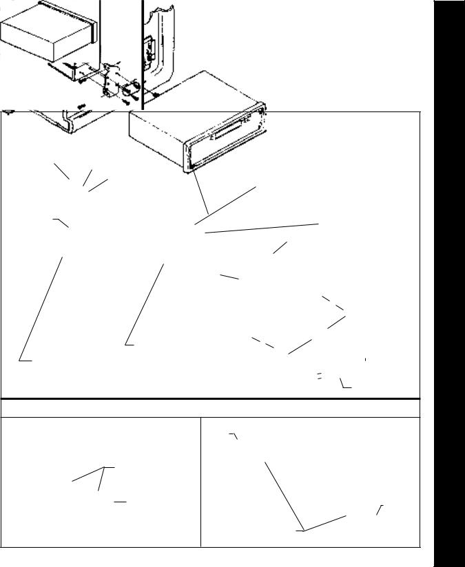
UNIVERSAL INSTALLATION USING MOUNTING SLEEVE
EXISTINGDASHOPENING(FILEEDGESTOFITIF NECESSARY-DONOT OVERFILE)
NOTE: IF DASH IS SOLID, USE MOUNTING SLEEVE AS A TEMPLATE & CUT OPENING
NUT |
|
|
BEND TOP TABS |
||||
|
|||||||
|
|
|
|
PERFORATED STRAP |
|||
|
|
|
|
||||
|
|
|
|
|
|
FASTEN THIS END TO |
|
|
|
|
|
|
|
||
|
|
|
|
|
|
UPWARD |
|
|
|
|
|
|
|
SCREW STUD ON |
|
|
|
|
|
|
|
|
|
|
|
|
|
|
|
REAR OF CHASSIS |
|
SCREW |
BEND BOTTOM TABS |
|
DOWNWARD |
||
|
||
|
RADIO |
|
|
SCREW STUD |
MOUNTING SLEEVE
FASTEN THIS END TO SECURE PART
OF DASHBOARD.
DRILL HOLE IF NECESSARY.
REMOVAL
TOOLS
DETACHABLE
FRONT PANEL
ISO INSTALLATION
REMOVE THE PLASTIC FRAME FROM THE FRONT OF THE CHASSIS BY CAREFULLY UN-SNAPPINGIT.
UN-SNAP AT 2 PLACES
EACH ON TOP AND
BOTTOM
PLASTIC FRAME
TYPICAL INSTALLATION
MAX. SIZE
M5 x 8
MAX. SIZE
M5 x 8
FACTORYMOUNTING BRACKETS
INSTRUCTIONS IONINSTALLAT
2

RADIO WIRING
3
RADIO WIRING
REFER TO PAGE 4 FOR SPEAKER WIRING
AUTOMATIC ANTENNA ANTENNA
EXISTING
ANTENNA
CABLE
ANTENNA LEAD ON
REAR OF RADIO
BLUE
FUSEBLOCK
RED |
“RADIO” FUSE |
+ 12V ACCESSORY |
SCREW
BLACK |
CAR BATTERY |
|
METAL PART OF DASH |
||
|
||
(DRILL HOLE IF NECESSARY) |
|
YELLOW
IMPORTANT
YELLOWWIREMUSTBECONNECTEDASSHOWN
OR RADIO WILL NOT OPERATE PROPERLY
|
POSITIVE (+) TERMINAL |
4 PIN PLUGS |
12V BATTERY |
|
9 PIN PLUG
(SEE PAGE 4 FOR SPEAKER WIRING)
RADIO
 Loading...