

Page 1

Conguration Manual
AT&T activeARC® Performance Access Points
ARC1000MAP Single band IEEE802.11N
Access Point
Page 2

i
ARC1000MAP User’s Manual
Welcome!
This User’s Manual details how to set up the AT&T activeARC® ARC1000MAP access point for the very first time.
Intended audience
This guide is designed to be used by network managers, administrators, and technicians who are responsible for installing, networking
equipment in enterprise and service provider environments. Knowledge of telecommunication and internet protocol (IP) technologies
is assumed.
Finding product documentation
The AT&T activeARC® product and support documentation consists of a variety of manuals, installation guides, videos, knowledge
articles, sample designs, troubleshooting, and FAQ guides to assist you with the deployment of your new and innovative solution.
These and other documents are available for download at http://att.com/activearc or via the AT&T activeARC® Focus Member portal at
http://activearc.att.com/reseller/index.php.
To view PDF files, use Adobe Acrobat Reader® 5.0 or newer. Download Acrobat Reader for free from the Adobe website:
http://www.adobe.com/products.
Find additional documentation at: http://att.com/activearc.
Contact information
Phone: 855.MYARC11 (855.692.7211)
E-mail: support@activearc.att-mail.com
sales@activearc.att-mail.com
Icons
Table of Contents Contact Previous Page Next Page
Page 3

ii
ARC1000MAP User’s Manual
Welcome! ...........................................................................................i
Intended audience ................................................................................................. i
Finding product documentation ........................................................................ i
Contact information .............................................................................................. i
Icons .......................................................................................................................... i
Table of contents .............................................................................ii
Introduction ...................................................................................... 1
AT&T activeARC® series features .......................................................................2
Supported features of AT&T activeARC® web management ....................... 2
Before you start .............................................................................. 3
Package Contents .................................................................................................3
Setting up the access point.................................................................................3
How to log in to your new access point ...................................... 4
ARC1000MAP port diagram ................................................................................4
Login steps ..............................................................................................................5
Quit web network management .........................................................................6
FIT/FAT mode ......................................................................................................... 7
Introduction to the AT&T activeARC® web management ..... 9
Function definitions ..............................................................................................9
Basic Settings ..................................................................................11
Description of this access point ............................................................. 11
Device information .................................................................................... 11
Administrator password .......................................................................... 12
Serial settings ............................................................................................. 12
System settings ......................................................................................... 12
Status ...............................................................................................13
Interfaces .............................................................................................................. 13
Wired settings ............................................................................................ 13
Wireless settings ....................................................................................... 13
Explanation ................................................................................................. 14
Transmit/Receive ................................................................................................ 14
Access Point information status ............................................................14
Client Association................................................................................................ 15
Advanced Configuration ..............................................................16
Ethernet Settings ................................................................................................ 16
Wireless Settings ................................................................................................. 17
Radio ....................................................................................................................... 18
VAP (Virtual Access Point) ................................................................................. 19
Setting security through VAP ................................................................ 20
Setting up Static WEP security configuration ................................. 21
Setting up WPA Personal security configuration ............................ 21
Setting up WPA Enterprise security configuration .........................22
Setting None as your security configuration ...................................23
AP modes ...............................................................................................................24
Provisioning over NAT .................................................................. 25
NAT provisioning configuration ...................................................................... 26
NAT Ports .................................................................................................... 26
Access point NAT configuration ........................................................... 26
Services .......................................................................................... 27
Web Server ............................................................................................................27
NTP ..........................................................................................................................27
Table of contents
Page 4

iii
ARC1000MAP User’s Manual
Maintenance .................................................................................. 28
Configuration management ............................................................................ 28
Resetting an access point to default configuration ......................... 28
Saving current configuration file to a backup location via HTTP... 28
Saving current configuration file to a backup location via TFTP ... 29
Restoring a previously saved file via HTTP ......................................... 29
Restoring a previously saved file via TFTP .......................................... 30
How to reboot the access point ............................................................ 30
Upgrading AP firmware ...................................................................................... 31
Firmware upgrade section and definition ............................................ 31
Using HTTP to upgrade firmware versions .......................................... 31
Using TFTP to upgrade firmware versions...........................................33
Regulatory and compliance ....................................................... 35
Warranty ........................................................................................ 40
Page 5

1
ARC1000MAP User’s Manual
Introduction
AT&T activeARC® Series access points are designed for performance
in small business environments. The ARC1000MAP is a single band
IEEE802.11b/g/n access point (AP). This AP can be FAT (standalone intelligent APs) or FIT (controlled by the active500EM).
This flexibility gives businesses the ability to manage their data
networking infrastructure; creating efficiency and performance.
Performance
Data networks need to perform better in light of the growing
demand for connection, security, and performance at the wireless
edge of the network. Wireless access points must handle the initial
demand for Wi-Fi® connectivity as smart devices flood business
environments. The AT&T activeARC® ARC1000 intelligent access
point enables IT staff with management tools and features to meet
the growing needs of network users.
The AT&T activeARC® Series access point supports up to 32 performance users and load balances those users across various
frequency bands to ensure optimal resource use. Moreover, a business can set different levels of user access rights, as well as rate limit
a user by MAC and IP address. Flexible and feature-rich, the ARC1000 AP is a performance tool at the edge of the computer network.
Page 6

2
ARC1000MAP User’s Manual
AT&T activeARC® series features
Featured data support
• IPv4 Support
• IPv6 Support
• Supports static and DHCP connection
types
• VLAN Support
• IGMP Multicasting
Security
• Static WEP 64
• Static WEP 128
• WPA Personal (TKIP)
• WPA2 personal (TKIP/CCMP (AES))
• WPA Enterprise (RADIUS Support)
Wireless
• Supports 2.4 GHz wireless radios
• Supports IEEE802.11b/g/n modes
• Data rates up to 300Mbps
• Supports 16 SSIDs
Configuration status
• Interfaces
• Transmit/Receive
• Client Associations
Advanced configuration
• Ethernet Settings
• Wireless Settings
• Radio
• VAP
• AP Mode
Maintenance
• Configuration
• Upgrade
Supported features of AT&T activeARC® web management
• The operating systems supported by AT&T activeARC® web network management include the following: Windows XP®, Windows
Server® Enterprise Edition, Windows Server® Standard Edition, Windows Vista®, Windows 7®, Windows 8®, Linux®, and MAC® OS X
10.6/10.7.
• The browsers supported by AT&T activeARC® web network management include the following: Microsoft Internet Explorer® 8.0 and
higher, Firefox® 3.0, Google Chrome™, Safari® including higher versions of these browsers.
• The firewall of the Windows operating system limits the number of connected TCP. Occasionally, the page cannot be opened when
using web network management. To avoid this situation, turn off the firewall of the Windows operating system.
• After the software version of the access point has updated, clear the cache data of the browser before logging in to the access
point through the web network management. Otherwise, the content of AT&T activeARC® web network management may not be
fully displayed.
Page 7

3
ARC1000MAP User’s Manual
Before you start
Package Contents
Unpack the contents to verify:
• AT&T activeARC® ARC1000MAP
• 12V Power Adapter
• Wall-mount kit (kit also used for ceiling-mounting)
• Screw kit
• Support Contact and Set Up Instruction guide
Setting up the access point
Using your web browser to access and manage your new ARC1000MAP is a very simple process.
1. Power up the access point using the included 12V power adapter.
2. Connect your access point to your PC with an Ethernet cable (not provided).
3. Configure your PC/laptop IP address.
4. Launch your supported web browser and type in the IP address of the unit which is 192.168.1.10.
5. Enter the username admin and password admin.
Page 8
4
ARC1000MAP User’s Manual
How to log in to your new access point
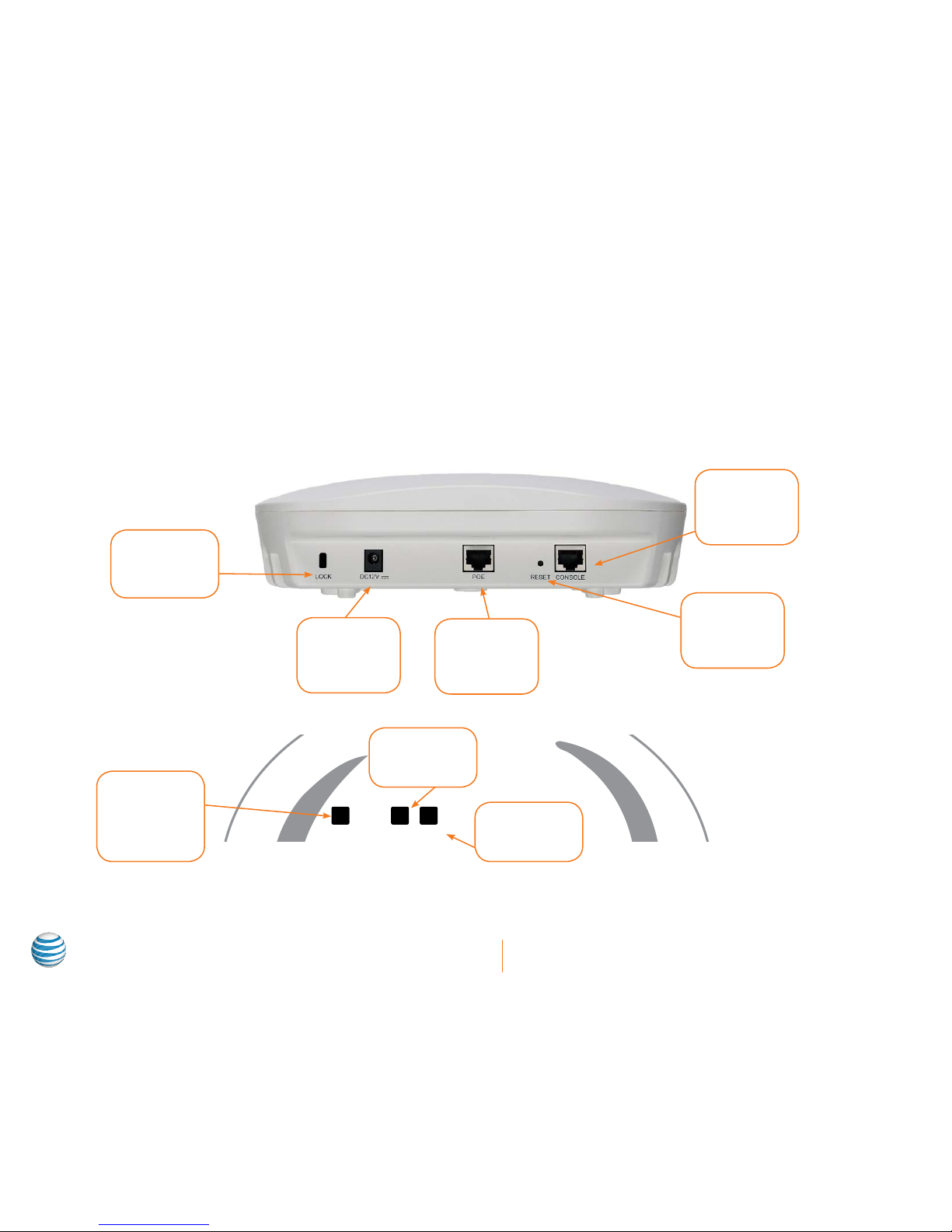
ARC1000MAP port diagram
ARC1000MAP LED diagram
2.4G LAN PWR
Security
Lock
Power
Input for
external power
supply
Network/PoE
Port
RJ-45 data
connection
Reset
To reset the
unit to factory
default
Console
RJ-45 port to
access CLI
management
Wireless
Indicators
Blinks when
wireless is
enabled
LAN
Lit shows
Ethernet link
Power
Lit when powered
up
Page 9

5
ARC1000MAP User’s Manual
Login steps
1. Power up the access point
Plug your device into electrical sockets using the 12V power adapter included with the access point. The ARC1000MAP indoor AP
supports local power and PoE power. Users can choose their method according to their actual network environment. Check to make
sure the power is properly grounded before powering up the unit. After adding power, check to make sure that the PWR LED on the
AP lights up.
2. Connect the access point to your PC
Use a RJ-45 Ethernet cable (not included) to connect a PC or laptop to the access point’s PoE port. The LED marked LAN will light
up after an Ethernet cable is successfully connected to the access point and PC port.
or
Figure 1.1: Environment of web network management
3. Configure your PC/laptop IP address
Configure the TCP/IP address on your PC or laptop so that it’s within the same TCP/IP address range as the access point. You will
need to set the address as a Static IP address. For more information on how to do this, please refer to your PC’s operating system
manual. For example, change the IP address to 192.168.1.0/24 to ensure that both the PC and the device are in the same IP subnet.
The default IP address of the access point is 192.168.1.10. Once completed, if needed, ensure that the PC can communicate with the
access point by running a Ping Test. If you’re not sure how to conduct a ping test on your machine, please consult your PC manual
or an online resource. Running a ping test might differ based on your operating system or type of PC/laptop manufacturer.
4. Launch your PC’s web browser
Open up a web browser and type http://192.168.1.10 in the address bar, and then press Enter.
Page 10
6
ARC1000MAP User’s Manual
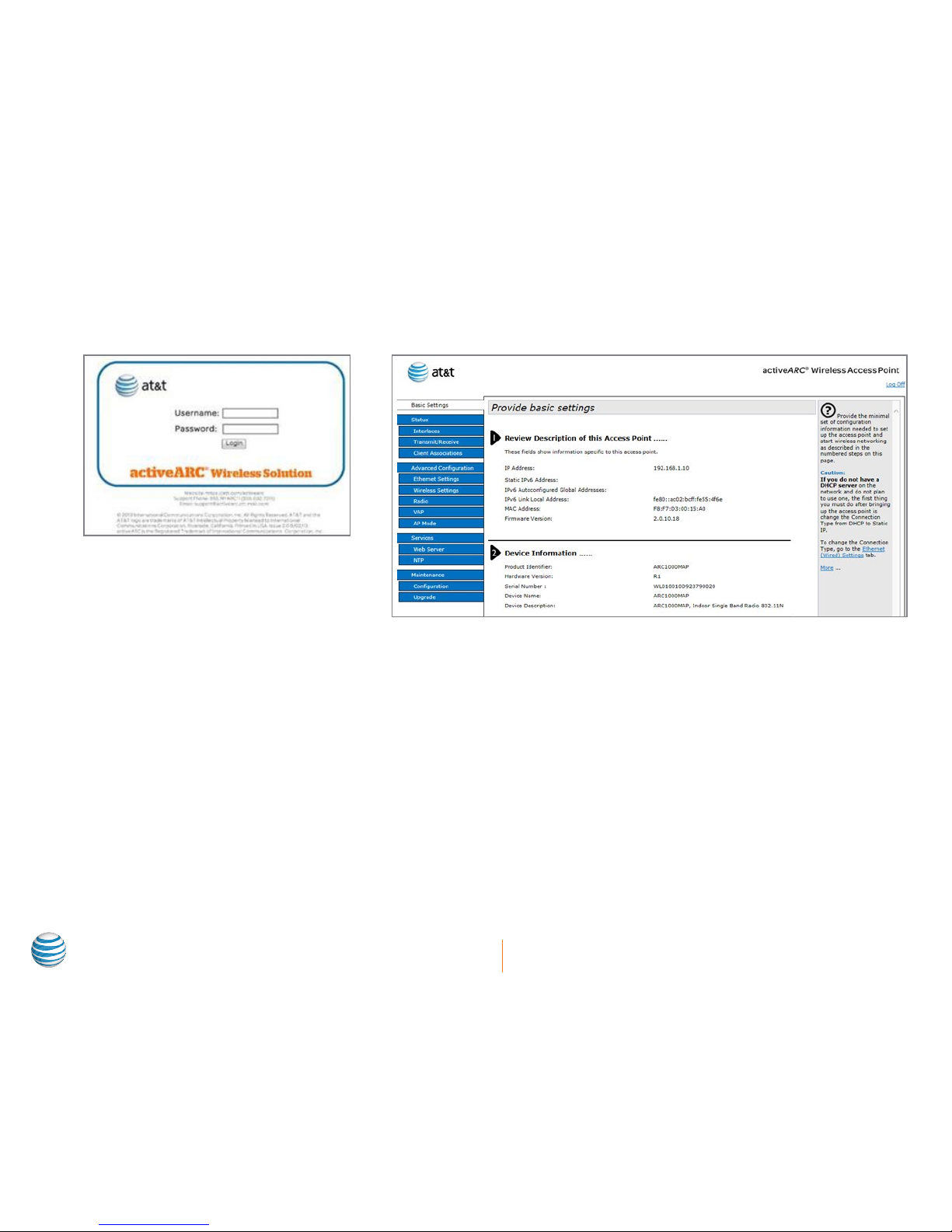
5. Enter the username and password
On the login page, as shown in Figure 1.2 below, type admin in both the Username field and in the Password field, then click Login.
Log on screen after entering TCP/IP address Management interface visible after entering user/password
Figure 1.2: Web network management login page Figure 1.3: Home page of web network management
Quit web network management
Click Log Off on the upper right-hand corner on the Web Network Management page to quit and exit. For security purposes, if the
Page 11
7
ARC1000MAP User’s Manual
system is left unattended for more than 5 minutes, the user will be logged out. The user will be required to log back into the web
management interface to continue configuring the access point.
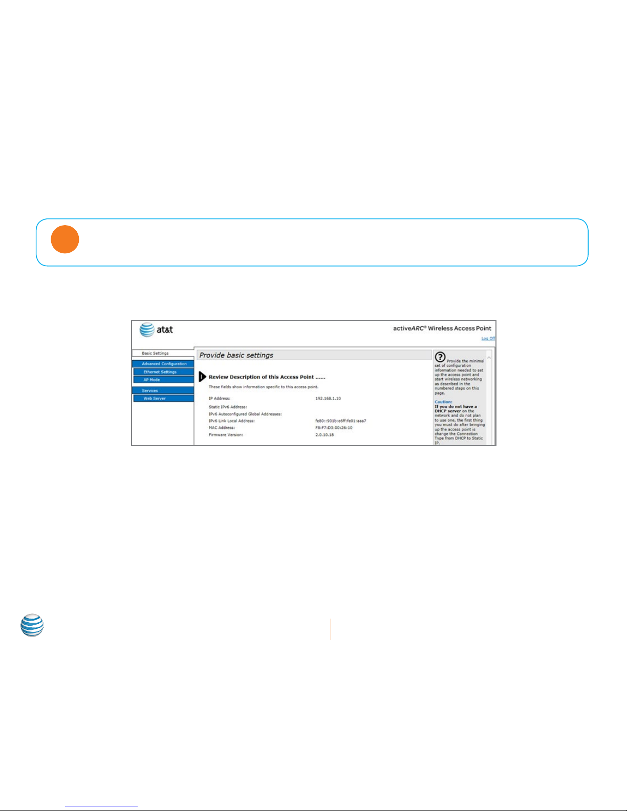
If the first screen you see is one with a limited blue navigation side bar as in Figure 1.4 below, then your access
point is in FIT (controller managed) mode. To operate the access point in FAT (stand-alone) mode, ensure
your AP mode is set to FAT mode. The default mode is FIT.
Note
FIT/FAT mode
FIT mode is designed to operate with an AT&T activeARC® Access Controller (AC).
Figure 1.4: Web management interface in FIT mode
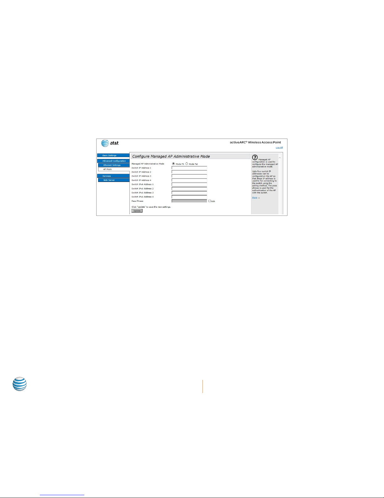
To change from FIT (controller managed) to FAT (stand-alone) follow these three simple steps:
1. Select AP Mode from the navigation bar.
2. Select Mode FAT.
Page 12
8
ARC1000MAP User’s Manual
3. Click Update.
Wait until the unit has refreshed the browser screen. You will need to log in after the refresh.
Figure 1.5: Configure Managed AP Administrative Mode page
Page 13
9
ARC1000MAP User’s Manual
Introduction to the AT&T activeARC® web management
Function definitions
Figure 1.6 provides a quick view of the AT&T activeARC® management features:
Figure 1.6: AT&T activeARC® management features
Page 14

10
ARC1000MAP User’s Manual
Menu/label Sub-menu label Description
Basic settings Shows the IP address, hardware version, firmware version,
MAC address, and device information. The administrator
password, serial ports configuration, and System Settings
can also be configured.
Status Interfaces Shows the real-time wired and wireless configuration of the
AP.
Transmit/Receive Shows the virtual AP-enabling situation and the statistic of
sending and receiving packets of the AP.
Client associations Shows the information of sending and receiving packets of
the terminal, which has been associated with the AP.
Advanced Configuration Ethernet settings Configures the related wired configuration of the AP,
including host name, management VLAN, untagged VLAN,
connection type (DHCP/Static IP selection), and DNS server.
Wireless settings Configures the related wireless configuration of the AP,
including country code, RF switch, wireless mode, and
channel.
Radio Configures the detailed RF parameters, including RF switch,
wireless mode, channel, channel bandwidth, primary channel,
supporting short protection interval, STBC mode, protection,
beacon frame interval, DTIM interval, fragment threshold,
RTS threshold, maximum associated terminals number
(maximum stations), transmission power, multicast rate, and
supported rate.
VAP Configures the authentication mode of the virtual AP and the
related configuration.
Modes of AP Configures the modes and IP address of the AP.
Services Web server Configures the http server status, HTTP server port,
maximum number of users, and timeout of the page.
NTP Configures the NTP server status, NTP server IP address, and
NTP update interval.
Maintenance Configuration Restarts the AP and restores it to factory configuration;
imports and exports files.
Upgrade Upgrades firmware of the AP.
Page 15

11
ARC1000MAP User’s Manual
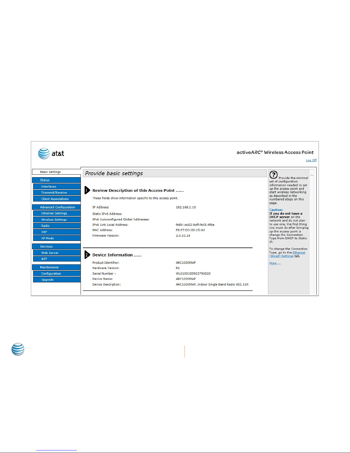
Basic Settings
Basic Settings shows detailed information about the ARC1000MAP access point and allows users to set administrator passwords, and
adjust serial settings and system settings.
Description of this access point
Item Description
IP Address Shows the current access point’s IP address.
IPv6 Address Shows the IPv6 address of the current access
point.
IPv6 Autoconfigured
Global Addresses
Shows the IPv6 auto configured global
address of the access point.
IPv6 Link Local
Address
Shows the IPv6 link local address of the
current access point.
MAC Address Shows the current access point’s MAC
address.
Firmware Version Shows the current access point’s firmware
version.
Device information
Item Description
Product Identifier Shows the current access point’s product
name.
Hardware Version Shows the current access point’s hardware
version.
Serial Number Shows the current access point’s serial
number.
Device Name Shows the name of the current access point.
Device Description Shows the current device’s description.
Figure 1.7: Basic settings tab in web management
Page 16

12
ARC1000MAP User’s Manual
Administrator password
Item Description
Current Password Type the current administrator password.
New Password Type the new password.
Confirm New
Password
Retype the new password. It must be identical
to the value in the New Password field.
Serial settings
Item Description
Baud Rate Select the data transmission rate (Baud Rate). Baud rate of 115200 is the default.
System settings
Item Description
System Name Type the company name or AP name.
System Contact Type the contact name.
System Location Type the device location.
Page 17

13
ARC1000MAP User’s Manual
Status
Status provides data, including network information, statistics of sending and receiving IP packets, and the associated terminal. The
following overview will show users how to view, edit, and change a variety of setting associated with their new edge wireless device.
Interfaces
Wired settings
Item Description
MAC Address Displays the access point’s MAC address.
Management VLAN ID Displays the current access point’s VLAN ID.
IP Address Displays the current access point’s IP address.
Subnet Mask Displays the current access point’s subnet mask.
IPv6 Address Displays the static IPv6 address of the access point.
Static IPv6 Address
Prefix Length
Displays the prefix length of the static IPv6 address.
IPv6 Autoconfigured
Global Addresses
Displays the automatically configured IPv6 address
list.
IPv6 Link Local
Address
Displays the automatically configured IPv6 address
list.
Default IPv6 Gateway Displays the default IPv6 gateway of the access point.
DNS-1 Displays the IP address of the DNS-1 server for the
access point.
DNS-2 Displays the IP address of the DNS-2 server for the
access point.
Default Gateway Displays the access point’s default gateway.
Wireless settings
Item Description
MAC Address Displays the MAC address information of RF1 (Radio 1).
Mode Displays the wireless mode information of RF1 (Radio 1) .
Channel Displays the channel information of RF1 (Radio 1).
Figure 1.8: Status tab in web management
Page 18

14
ARC1000MAP User’s Manual
Explanation
Click Edit to link to the wired and wireless configuration page.
Transmit/Receive
Access Point information status
Access Point Information Status shows the physical ports and the status of the virtual AP.
Item Description
Interface The name of Ethernet port or VAP port.
Status This shows the current status of the
networked device. It shows ‘up’ for on and
‘down’ for off.
MAC Address MAC address of the specific port (interface).
Every interface of the AP has the unparalleled
MAC address. Each RF interface has a
different MAC address.
VLAN ID VLAN number (VLAN ID). You can use VLAN
to create multiple internal and customer
networks on the same AP.
Name (SSID) Wireless network name, also named SSID,
which indicates the WLAN.
Item Description
Interface The name of the Ethernet port or VAP port.
Total Packets Displays the number of the packets that the AP sent (in the sending packet table) or received (in the receiving packet
table).
Total Bytes Displays the number of the bytes that the AP sent (in the sending packet table) or received (in the receiving packet
table).
Total Dropped Packets Displays the number of the sent (in the sending packet table) or received (in the receiving packet table) packets that
the AP dropped.
Total Dropped Bytes Displays the number of the sent (in the sending packet table) or received (in the receiving packet table) bytes that the
AP dropped.
Errors Displays the total number of errors the AP sent or received.
Figure 1.9: Transmitting/Receive tab in web management
Page 19

15
ARC1000MAP User’s Manual
Client Association
Associated terminal showing:
Item Description
Network The SSID of the terminal
associated network
Station The MAC address of the
associated terminal
Station and Client are the same thing.
These are the users of the system.
Note
Item Description
Status Authenticated The IEEE 802.11 authentication status.
Associated The IEEE 802.11 association status.
From Station Packets The number of packets and bytes received from the terminal and the number of dropped
packets and bytes after being received.
Bytes
Dropped Packets
Dropped Bytes
To Station Packets The number of packets and bytes the terminal received and the number of dropped packets
and bytes in transmission.
Bytes
Dropped Packets
Dropped Bytes
Figure 1.10: Client Association tab in web management
Page 20

16
ARC1000MAP User’s Manual
Advanced Configuration
Advanced Configuration includes wired configuration, wireless configuration, configuring RF parameters, virtual AP, and AP modes.
Ethernet Settings
Item Description
Host Name The AP host name.
MAC Address The AP Ethernet port’s MAC address.
Management VLAN ID Used to access the VLAN that is associated
with the IP address of the AP.
Untagged VLAN If the untagged VLAN is disabled, all packets
will be marked with the same VLAN number.
Untagged VLAN ID The packet transmitted in this VLAN has no
tagged VLAN number.
Connection Type Type of connection to configure the IP
address for the AP.
Static IP Address Configure the static IP address. If the
connection type selected is DHCP, this
property cannot be used.
Subnet Mask Configure the subnet mask. If the connection
type selected is DHCP, this property cannot
be used.
Default Gateway Configure the default gateway. If the
connection type selected is DHCP, this
property cannot be used.
DNS Server Configure the DNS mode. Under the manually
appointed mode, the DNS address can be
configured to analyze the domain name.
Item Description
IPv6 Admin Mode If the IPv6 Admin Mode is enabled, the access point can be managed via the IPv6 address. If both IPv4 and IPv6 are
enabled, IPv4 will be preferred.
IPv6 Auto Config
Admin Mode
If enabled, the access point sets the IPv6 address automatically.
Static IPv6 Address Displays the static IPv6 address of the access point.
Figure 1.11: Advanced Configuration tab in web management
Page 21

17
ARC1000MAP User’s Manual
Item Description
Static IPv6 Address
Prefix Length
Displays the prefix length of the static IPv6 address.
IPv6 Autoconfigured
Global Addresses
Displays the IPv6 address or addresses that the access point sets dynamically.
IPv6 Link Local
Address
Displays the IPv6 link local address of the access point.
Default IPv6 Gateway Displays the default IPv6 gateway of the access point.
IPv6 DNS Server Displays the IPv6 DNS server address of the access point.
Wireless Settings
Item Description
Country Choose the country of use.
Radio Interface Select whether the RF for the access point is
On or Off.
MAC Address Displays the MAC address of the RF interface.
Mode The PHY (Physical Layer) standard used by RF.
Channel Select the channel.
Figure 1.12: Wireless Settings tab in web management
Page 22

18
ARC1000MAP User’s Manual
Radio
Radio provides RF parameters.
Item Description
Radio Select the configured RF.
Status Enable/disable the RF.
Mode The PHY standard used by RF.
Channel Select the channel.
Channel Bandwidth The channel bandwidth of 802.11n mode.
Primary Channel The mode of the primary channel (only available in
802.11n mode).
Short Guard Interval
Supported
Configure the short guard. (only available in 802.11n
mode).
STBC Mode Configure the STBC mode. (only in 802.11n mode).
Protection Configure the protection function. (a/b/g/n for all
modes).
Beacon Interval Configure the beacon interval. (a/b/g/n for all modes).
DTIM Interval Configure the DTIM interval. (a/b/g/n for all modes).
Fragment Threshold Configure the fragment threshold. (a/b/g/n for all
modes).
RTS Threshold Configure the RTS threshold. (a/b/g/n for all modes).
Maximum Stations Configure the maximum number of associated
stations. (a/b/g/n for all modes).
Transmit Power Configure the percentage of RF transmission power.
(a/b/g/n for all modes).
Fixed multicast Rate Configure the supported multicast rate. (a/b/g/n for all
modes).
Rate Sets Configure the transmission rate set and the basic
broadcast rate set that is supported by RF. (a/b/g/n for
all modes).
Figure 1.13: Radio tab in web management
Page 23

19
ARC1000MAP User’s Manual
VAP (Virtual Access Point)
Item Description
Radio Select the RF to be configured.
VAP Shows the ID number of the virtual AP.
Enabled Check if the status of the virtual AP is Enabled.
VLAN ID Enter the VLAN for the associated client’s virtual AP.
SSID Enter the name of the wireless network.
Broadcast SSID Select if the SSID is to be broadcast.
Security Select the security mode.
Figure 1.14: VAP (Virtual Access Point) settings tab in web
management
Page 24

20
ARC1000MAP User’s Manual
Setting security through VAP
Modifying the virtual access point setting is simple and provides four (4) different security modes: None, Static WEP, WPA Personal,
and WPA Enterprise. Based on the option the user selects, additional configuration options will be shown.
Select a security type from the drop-down menu. Security configuration options based on the selection .
Figure 1.15: Security type drop-down under VAP tab
Figure 1.16: Security configuration options under Security in VAP tab
Page 25

21
ARC1000MAP User’s Manual
Setting up Static WEP security configuration
If WEP is your required security method, select Static WEP from the drop-down list. Once Static WEP is selected, the user can choose
Transfer key index, Key Length and Type, and even Authentication method (Open system or Shared key) during the configuration
process. Figure 1.17 shows the WEP setting with a Static WEP setting. Provide the WEP keys to the client in order to pass the
authentication or the decryption packet.
Item Description
Transfer Key Index Select the key index.
Key Length Select the key length.
Key Type Select the key type.
WEP Keys Enter the WEP keys (up to four
entries).
Authentication Select the authentication mode.
Setting up WPA Personal security configuration
Select the security configuration as WPA Personal from the drop-down list. Once WPA is selected, the user can select more detailed
security settings. In this secondary box, as shown in Figure 1.18, users can select various types of encryption methods and broadcast
refresh rates. The key, as noted below, should be provided to the client for authentication.
Item Description
WPA Versions Select the WPA version.
Cipher Suites Select the cipher suites.
Key Enter the pre-shared password key.
Broadcast Key
Refresh Rate
Enter the broadcast key refresh rate.
Figure 1.17: Static WEP selection from drop-down list
Figure 1.18: WPA Personal selection from drop-down list
Page 26

22
ARC1000MAP User’s Manual
Setting up WPA Enterprise security configuration
Select the security configuration WPA Enterprise from the drop-down list for advanced security options. Once WPA Enterprise is
selected, numerous configuration fields and detailed configuration information will be displayed. The previously used username and
password from the radius server should be input in the client to pass the authentication.
Item Description
WPA Versions Select the WPA version.
Cipher Suites Select the cipher suites.
Radius IP Address Enter the IP address of the radius
server.
Radius IP Address of
1–3
Enter the IP address of the backup
radius servers.
Radius Key Enter the radius server key (up to 64
characters pre-shared key).
Radius Key of 1–3 Enter the key of the backup radius
server.
Active Server Select the radius server.
Broadcast Key
Refresh Rate (0-
86400)
Enter the broadcast key refresh rate.
Session Key Refresh
Rate (0-86400)
Enter the session key refresh rate.
Figure 1.19: WPA Enterprise selection from drop-down list
Page 27

23
ARC1000MAP User’s Manual
Setting None as your security configuration
The AP can be configured to not have a security setting. IT administrators can choose to set the security configuration as None,
effectively turning off all of the AP’s security features. In this configuration, users can navigate to the access point without security
requirements.
It is NOT recommended to turn off wireless security.
Note
Figure 1.20: None selection from drop-down list
Page 28

24
ARC1000MAP User’s Manual
AP modes
AP modes can be switched between FIT or FAT access point modes. When in FIT mode, the access point is controlled by the central
network controller system, the active EM Series controllers. In FAT mode, the access point will operate as a single device, providing
access to any client connected to it.
Figure 1.21: AP mode configuration
Item Description
Managed AP Administrative Mode Configure the AP modes.
Switch IP Address of 1–4 Configure the IP address of the AC under the thin AP mode (FIT AP Mode).
Switch IPv6 Address of 1-4 Configure the IPv6 address of the AC under the thin AP mode (FIT AP Mode).
Pass Phrase Configure the password of the associated authentication between the AP and the AC under the thin
AP mode (FIT AP Mode).
Page 29

25
ARC1000MAP User’s Manual
Provisioning over NAT
The AT&T activeARC® solution can be deployed over a NAT environment. NAT (Network Address Translation or Network Address
Translator) is the translation of an Internet Protocol address used within one network to a different IP address known within another
network. This allows users to utilize the AT&T activeARC® Access Point products in remote office environments for enterprise
deployments, and in multi-client environments for managed service provider deployments. For example, the AT&T activeARC®
active500EM controller can be located in the one central location or Network Operations Center and communicate with the AT&T
activeARC® access points in remote locations. The AT&T activeARC® solution essentially virtualizes the Internet cloud as a direct link to
devices.
The active500EM can support up to 256 AT&T activeARC® access points over NAT configurations and each AT&T activeARC® Access
Point has the capability to configure up to three active500EM controllers as backups for redundancy in case the master controller is
inaccessible for any reason.
The NAT AP Provisioning figure below displays a typical network topological layout of an access point provisioning over a NAT based
environment. Here, both the AT&T activeARC® access points and the active500EM controller are both behind NAT based firewalls
utilizing private IP addresses.
Figure 1.22 Typical network of Access Point Provisioning over NAT based environment
Page 30

26
ARC1000MAP User’s Manual
NAT provisioning configuration
Both the AT&T activeARC® APs and active500EM Access Controller must be configured to complete the NAT configuration.
NAT Ports
The active500EM and associated access points use TCP ports 57776-57779 to communicate over NAT. Set a policy on your NAT
firewalls, gateways, and/or routers to open TCP ports 57776-57779 to all associated AT&T activeARC
®
devices on the local and remote
networks. Please refer to the NAT device/firewall manufacturer’s user documentation for proper configuration.
Access point NAT configuration
Configure the AT&T activeARC® Access Point in Fit
mode by selecting Advanced Configuration > AP
Mode and choosing Mode Fit.
Under Configure Managed AP Administrative
Mode, enter the global/public IP address of the NAT
supporting firewall, gateway, and/or router, which
is front of the active500EM Access Controller (e.g.
174.210.254.69), in the Switch IP Address 1 field. Click
Update.
If the active500EM Access Controller is not set up
behind a NAT supporting gateway and is placed
directly on a public IP address, then that public IP
address would be entered in the Switch IP Address 1
field.
Up to three additional active500EM Access Controller IP addresses can be entered in the fields Switch IP Address 2, Switch IP Address
3, and Switch IP Address 4 as backups.
Note: There are specific AT&T activeARC
®
active500EM Access Controller configurations required to setup Access Point provisioning
over NAT based environments. Please follow the instructions detailed in Chapter 10 of the active500EM Wireless Web User Interface
Manual to complete the provisioning.
Figure 1.23 NAT Provisioning Access Point Configuration
Page 31

27
ARC1000MAP User’s Manual
Services
Services include web server and NTP server configuration.
Web Server
Item Description
HTTP Server Status Disable/enable the HTTP server
status.
HTTP Port Configures http server port number.
The web can only be accessed via the
identified port.
Maximum Sessions The maximum number of web page
sessions which can be viewed on the
Access Point at the same time.
Session Timeout
(minutes)
Configured timeout value. If the
timeout value is exceeded, the
session will log out automatically.
NTP
Item Description
Status Enable/disable the NTP server.
Server Address Configures the IP address of the NTP
server.
Interval Configures the synchronized interval.
Figure 1.24: Web server configuration
Figure 1.25: NTP server configuration
Page 32

28
ARC1000MAP User’s Manual
Maintenance
Maintenance includes configuration management and the firmware upgrade process.
Configuration management
Resetting an access point to default
configuration
Click Reset to restore the default configuration of AP. The
default working mode of an AT&T activeARC® performance
access point is FIT mode.
ALERT: Resetting the configuration files will replace
old configurations. There is no recovery for the old
configuration unless the user saved a separate file of the
older configuration.
Saving current configuration file to a backup
location via HTTP
Select the download method as HTTP mode. Click
Download, and then confirm the download. The current
configuration files of AP will be downloaded directly
through HTTP.
Figure 1.26 Configuration management under Maintenance tab
Page 33

29
ARC1000MAP User’s Manual
Saving current configuration file to a backup location via TFTP
Choose the download method as TFTP mode, type the configuration file name (the format is *.xml) and the IP address of TFTP server.
Click Download, and confirm it. The configuration file will be downloaded directly to the appointed TFTP server. The file name is the
input name.
Figure 1.27: Saving the current configuration - TFTP
Restoring a previously saved file via HTTP
Once HTTP upload method is selected, click Browse to locate your saved file and select and upload the appropriate file type (the
format is *.xml) to the access point. Once completed, the configuration must be saved by clicking Restore. The current configuration
will be replaced by the newly uploaded configuration file.
ALERT: Newly uploaded configuration files will replace old configurations. There is no recovery for the old configuration unless the user
saved a separate file of the older configuration.
Figure 1.28: Restoring configuration via HTTP
Page 34

30
ARC1000MAP User’s Manual
Restoring a previously saved file via TFTP
Once TFTP is selected, type the file name of the new configuration (file format is *.xml) and the IP address of the TFTP server. Once
completed, Restore, and confirm the request. The current configuration will be replaced by the newly uploaded configuration file.
ALERT: Newly uploaded configuration files will replace old configurations. There is no recovery for the old configuration unless the user
saved a separate file of the older configuration.
Figure 1.29: Restoring configuration via TFTP
How to reboot the access point
Click Reboot, and confirm the action. Once confirmed, the access point will reboot.
Figure 1.30: Reboot of access point
Page 35

31
ARC1000MAP User’s Manual
Upgrading AP firmware
The access point firmware upgrade process can be completed via HTTP or TFTP. Each process is simple and can be completed by any
IT administrator. Current firmware can be downloaded by accessing the AT&T activeARC
®
Focus Member portal at http://activearc.
att.com/reseller/index.php, clicking on Document Library, and downloading the most recent file listed under Firmware Updates.
Download the .tar file to a location on your PC and select that file in Step #3 listed below.
Firmware upgrade section and definition
Figure 1.31: Firmware Upgrade
Item Description
Firmware Version Displays the current firmware version of the AP.
Upload Method Upload by either HTTP or TFTP.
New Firmware Image Click Browse to find firmware version to be uploaded.
Upgrade Click Upgrade to confirm uploading of new firmware image.
Using HTTP to upgrade firmware versions
To complete the firmware upgrade process using HTTP:
1. Select HTTP as the upgrade method.
2. If you know the path of the new firmware file, click Browse to locate the file.
The upgrade file type for the firmware must be a “.tar” file. Do not try to use a bin file or other
types of files or this process will fail.
Note
Page 36

32
ARC1000MAP User’s Manual
3. Once the file is selected, click Upgrade to apply the new firmware file. After clicking Upgrade, there will be a secondary window
describing the upgrade progress.
Figure 1.32: Upgrade firmware using HTTP
4. Click Confirm to start the upgrading process.
By clicking Upgrade and Confirm, the upgrade process will start.
Note
The upgrade process will take a few minutes and progress will be displayed on the GUI screen. During this period, the AP cannot
be accessed. Do not turn off the AP power during the upgrade process. Once the upgrade process is complete, the AP will
automatically restart.
Page 37

33
ARC1000MAP User’s Manual
5. To verify whether the firmware upgrade was successful, check the firmware version on the firmware management page (or the
basic configuration label). If the upgrade was successful, the newer version will be shown in the Firmware Version section.
Figure 1.33: Firmware version under Basic Settings
Using TFTP to upgrade firmware versions
To complete the firmware upgrade process using TFTP:
1. Select TFTP as the uploading method.
2. In the Image Filename text box, type the name of the mirror file (1 to 256 characters). The name includes the integral path of the
mirror file.
For example, if the file is ap_upgrade.tar in the file location of /share/builds/ap, the uploaded location would be /share/builds/ap/
ap_upgrade.tar in the text box.
The upgrade file must be a ‘*.tar’ file. Do not use a bin or other type of file, as these will fail to run.
Note
3. Enter the IP address of the TFTP server.
Page 38

34
ARC1000MAP User’s Manual
4. Click Upgrade.
After clicking Upgrade, a window describing the upgrading process appears.
Figure 1.34: Upgrade Firmware Using TFTP
5. Click Confirm to start the final upgrade process.
By confirming the upgrade process, as well as approving the secondary confirmation, the
upgrade process will start. This process will replace any firmware with the uploaded one.
Note
The upgrade process will take a few minutes. During this period, the AP cannot be accessed. Do not turn off the AP power during the
upgrade process. Once completed, the AP will automatically restart.
6. To confirm that the new firmware is properly uploaded, check the firmware version in the firmware management page (or the basic
configuration label). If the upgrade was successful, the newer version will show in the Firmware Version section.
Page 39

35
ARC1000MAP User’s Manual
Regulatory and compliance
The AT&T activeARC® access points must be installed and used in strict accordance with the manufacturer’s instructions as described
in the user documentation that comes with the product. This product contains encryption. It is unlawful to export out of the United
States without obtaining a U.S. Export License.
This product does not contain any user serviceable components. Any unauthorized product changes or modifications will invalidate
ICC’s warranty and all applicable regulatory certifications and approvals.
Only antennas specified for your region by ICC can be used with this product. The use of external amplifiers or non-ICC antennas may
invalidate regulatory certifications and approvals.
Declaration of ROHS compliance
International Communications Corporation hereby declares that the product AT&T activeARC® access point has been designed
and manufactured in accordance with Directive 2002/95/EC of the European Commission on the restriction of certain hazardous
substances in electrical and electronic equipment. (ROHS)
FCC warning
This device generates and radiates radio-frequency energy. In order to comply with FCC radio-frequency exposure guidelines for an
uncontrolled environment, this equipment must be installed and operated while maintaining a minimum body-to-antenna distance of
20 cm (approximately 8 in).
Canada warning
The radio equipment installer must ensure that the antenna is located or pointed so that it does not emit RF field in excess of Health
Canada limits for the general population; consult Safety Code 6, obtainable from Health Canada’s website: www.hc-sc.gc.ca/rpb.
CAUTION: Exposure to radio frequency radiation
Page 40

36
ARC1000MAP User’s Manual
This equipment complies with IC radiation exposure limits set forth for an uncontrolled environment. End users must follow the
specific operating instructions for satisfying RF exposure compliance. This equipment should be installed and operated with a
minimum distance of 20 cm between the radiator and your body.
USA — Radio frequency requirements
This device must not be co-located or operated in conjunction with any other antenna or transmitter. This device is for indoor use only
when using channels 36, 40, 44 or 48 in the 5.15 to 5.25 GHz frequency range.
High power radars are allocated as primary users of the 5.25 to 5.35 GHz and 5.65 to 5.85 GHz bands. These radar stations can cause
interference and/or damage this device.
Industry Canada — Radio frequency compliance
This device complies with RSS 210 of Industry Canada. Operation is subject to the following two conditions: (1) this device may not
cause interference, and (2) this device must accept any interference, including interference that may cause undesired operation of
this device. L’utilisation de ce dispositif est autorisée seulement aux conditions suivantes: (1) il ne doit pas produire de brouillage et
(2) l’utilisateur du dispositif doit étre prêt à accepter tout brouillage radioélectrique reçu, même si ce brouillage est susceptible de
compromettre le fonctionnement du dispositif.
The term “IC” before the equipment certification number only signifies that the Industry Canada technical specifications were met.
To reduce potential radio interference to other users, the antenna type and its gain should be chosen so that the equivalent
isotropically radiated power (EIRP) is not more than the amount required for successful communication. To prevent radio interference
to the licensed service, this device is intended to be operated indoors and away from windows to provide maximum shielding.
Equipment (or its transmit antenna) that is installed outdoors is subject to licensing.
Pour empecher que cet appareil cause du brouillage au service faisant l’objet d’une licence, il doit etre utilize a l’interieur et devrait etre
place loin des fenetres afin de Fournier un ecram de blindage maximal. Si le matriel (ou son antenne d’emission) est installe a l’exterieur,
il doit faire l’objet d’une licence.
High-power radars are allocated as primary users of the 5.25 to 5.35 GHz and 5.65 to 5.85 GHz bands. These radar stations can cause
interference and/or damage this device.
This device must not be co-located or operated in conjunction with any other antenna or transmitter.
Page 41

37
ARC1000MAP User’s Manual
USA – Federal Communications Commission (FCC) EMC compliance
This equipment has been tested and found to comply with the limits for a Class B digital device, pursuant to Part 15 of the FCC Rules.
These limits are designed to provide reasonable protection against harmful interference in a residential installation. This equipment
generates, uses, and can radiate radio frequency energy and, if not installed and used in accordance with the instructions, may cause
harmful interference to radio communications.
However, there is no guarantee that interference will not occur in a particular installation. If this equipment does cause harmful
interference to radio or television reception, which can be determined by turning the equipment off and on, the user is encouraged to
try to correct the interference by one or more of the following measures:
• Reorient or relocate the receiving antenna.
• Increase the separation between the equipment and receiver.
• Connect the equipment into an outlet on a circuit different from that to which the receiver is connected.
• Consult the dealer or an experienced radio/TV technician for help.
The user may find the following booklet prepared by the Federal Communications Commission helpful: The Interference Handbook.
This booklet is available from the US Government Printing Office, Washington, DC 20402. Stock No. 004-000-0034504.
ICC is not responsible for any radio or television interference caused by unauthorized modification of the devices included with this
ICC Wireless 11b/g PoE Access Point, Model activeARC
®
, or the substitution or attachment of connecting cables and equipment other
than specified by ICC.
The correction of interference caused by such unauthorized modification, substitution, or attachment will be the responsibility of the
user.
Changes or modifications not expressly approved by ICC could void the user’s authority to operate this equipment.
Manufacturer’s FCC declaration of conformity
Model Number: ARC1000MAP International Communications Corporation Equipment Type: WLAN Access Point
Complies with Part 15 of the FCC rules. Operation is subject to the following two conditions: (1) this device may not cause
harmful interference, and (2) this device must accept any interference received, including interference that may cause undesired
operation.
Page 42

38
ARC1000MAP User’s Manual
Safety compliance notice
This device has been tested and certified according to the following safety standards and is intended for use only in information
technology equipment, which has been tested to these or other equivalent standards:
• EN60950-1
• IEC 60950-1
• UL 60950-1
Industry Canada – RF compliance
This device complies with RSS 210 of Industry Canada.
Operation is subject to the following two conditions: (1) this device may not cause interference, and (2) this device must accept any
interference, including interference that may cause undesired operation of this device.
L’utilisation de ce dispositif est autorisée seulement aux conditions suivantes: (1) il ne doit pas produire de brouillage et (2) l’utilisateur
du dispositif doit étre prêt à accepter tout brouillage radioélectrique reçu, même si ce brouillage est susceptible de compromettre le
fonctionnement du dispositif.
The term “IC” before the equipment certification number only signifies that the Industry Canada technical specifications were met.
To reduce potential radio interference to other users, the antenna type and its gain should be chosen so that the equivalent
isotropically radiated power (EIRP) is not more than the amount required for successful communication. To prevent radio interference
to the licensed service, this device is intended to be operated indoors and away from windows to provide maximum shielding.
Equipment (or its transmit antenna) that is installed outdoors is subject to licensing.
Pour empecher que cet appareil cause du brouillage au service faisant l’objet d’une licence, il doit etre utilize a l’interieur et devrait etre
place loin des fenetres afin de Fournier un ecram de blindage maximal. Si le matriel (ou son antenne d’emission) est installe a l’exterieur,
il doit faire l’objet d’une licence.
High-power radars are allocated as primary users of the 5.25 to 5.35 GHz and 5.65 to 5.85 GHz bands. These radar stations can cause
interference and/or damage this device.
This device must not be co-located or operated in conjunction with any other antenna or transmitter.
Page 43

39
ARC1000MAP User’s Manual
Industry Canada – Emissions compliance statement
This Class B digital apparatus complies with Canadian ICES-003. Avis de Conformité à la Réglementation d’Industrie Canada.
Cet appareil numérique de la classe B est conform à la norme NMB-003 du Canada.
Page 44

40
ARC1000MAP User’s Manual
Warranty
The AT&T brands are used under license. Any and all questions about this product should be directed to International Communications Corporation, Inc. at 1-855692-7211. The manufacturer of this AT&T Product (activeARC® product line), International Communications Corporation, Inc. (“ICC”), warrants its products to be
free from defects in workmanship and materials, under normal use and service, starting from the date the original purchaser purchased the product (based on the
invoice date on the authorized Partner’s invoice) from ICC or its Authorized reseller or distributor.
All activeARC
®
hardware, excluding fans and internal power supplies, is under warranty for the life of the product and 2 years after the product is End-of-Life. Fans
and internal power supplies are not included in the lifetime warranty and are covered by a warranty period of five (5) years. Should any activeARC® product fail to
function as warranted, ICC may, at its own discretion, either repair or replace the defective product with a similar or functionally equivalent product, during the
applicable warranty period. ICC will endeavor to repair or replace any product returned under warranty within thirty (30) days of its receipt of the returned product.
End-of-Life of a product is defined as the date that ICC no longer makes the product readily available for sale in its authorized channels. Support for activeARC®
hardware can be extended via an activeARC® Service Contract.
ICC warrants that for a period of two (2) years from the invoice date on the authorized ICC distributor’s invoice that the Software supplied by ICC will perform
substantially in accordance with the specifications set forth in the activeARC® user guide accompanying the Product. In the case of a defect, which is reproducible
by ICC, the Software will be either repaired or replaced, at ICC’s option.
All products that are returned to ICC become the property of ICC. Repaired or replacement products may be refurbished or contain refurbished materials. Any
replaced or repaired product carries the remainder of the initial warranty. ICC is not responsible for any Customer or custom software or firmware, configuration
information or Customer memory data contained in, stored on, or integrated with any products returned to ICC pursuant to any warranty. Customer must back up or
otherwise retain any such information or data prior to shipping product to ICC. Products returned to ICC should have any customer-installed accessory or add-on
components, such as expansion modules, removed prior to returning the product for replacement. ICC is not responsible for these items if they are returned to ICC
with the product.
Prior to returning any defective product, Customers must contact ICC for a Return Material Authorization number (“RMA”). Proof of the original purchase may be
required. Any product returned to ICC without a valid RMA number clearly marked on the outside of the package will be returned to the customer at customer’s
expense. For warranty claims within the US and Canada, please call our toll-free customer support number at 1-855-692-7211. Customers are responsible for all
shipping charges and risk of loss from their location to ICC. ICC is responsible for return shipping charges and risk of loss from ICC to customer’s location.
WARRANTIES EXCLUSIVE: IF AN ICC PRODUCT DOES NOT OPERATE AS WARRANTED ABOVE, CUSTOMER’S SOLE REMEDY SHALL BE REPAIR OR REPLACEMENT
OF THE PRODUCT IN QUESTION, AT ICC’S OPTION. THE FOREGOING WARRANTIES AND REMEDIES ARE EXCLUSIVE AND ARE IN LIEU OF ALL OTHER WARRANTIES
OR CONDITIONS, EXPRESS OR IMPLIED, EITHER IN FACT OR BY OPERATION OF LAW, STATUTORY OR OTHERWISE, INCLUDING WARRANTIES OR CONDITIONS OF
MERCHANTABILITY AND FITNESS FOR A PARTICULAR PURPOSE. PRODUCTS ARE NOT WARRANTED TO OPERATE UNINTERRUPTED OR ERROR FREE. ICC NEITHER
ASSUMES NOR AUTHORIZES ANY OTHER PERSON TO ASSUME FOR IT ANY OTHER LIABILITY IN CONNECTION WITH THE SALE, INSTALLATION, MAINTENANCE
OR USE OF ITS PRODUCTS. ICC SHALL NOT BE LIABLE UNDER THIS WARRANTY IF ITS TESTING AND EXAMINATION DISCLOSE THE ALLEGED DEFECT IN THE
PRODUCT DOES NOT EXIST OR IF IN ITS SOLE JUDGMENT THE ALLEGED DEFECT WAS CAUSED BY CUSTOMER’S OR ANY THIRD PERSON’S MISUSE, NEGLECT,
IMPROPER INSTALLATION OR TESTING, UNAUTHORIZED ATTEMPTS TO REPAIR, OR ANY OTHER CAUSE BEYOND THE RANGE OF THE INTENDED USE, OR BY
ACCIDENT, FIRE, LIGHTNING OR OTHER HAZARD.
LIMITATION OF LIABILIT Y: TO THE FULLEST EXTENT ALLOWED BY LAW, WHETHER BASED IN CONTRACT OR TORT (INCLUDING NEGLIGENCE), ICC SHALL NOT
BE LIABLE FOR INCIDENTAL, CONSEQUENTIAL, INDIRECT, SPECIAL, OR PUNITIVE DAMAGES OF ANY KIND, OR FOR LOSS OF REVENUE, LOSS OF PROFIT, LOSS OF
BUSINESS, OR OTHER FINANCIAL LOSS ARISING OUT OF OR IN CONNECTION WITH THE SALE, INSTALLATION, MAINTENANCE, USE, PERFORMANCE, FAILURE, OR
INTERRUPTION OF ITS PRODUCTS, EVEN IF ICC OR ITS AUTHORIZED DISTRIBUTOR OR RESELLER HAS BEEN ADVISED OF THE POSSIBILITY OF SUCH DAMAGES.
THE MAXIMUM LIABILITY OF ICC UNDER THIS WARRANTY IS LIMITED TO THE PURCHASE PRICE OF THE PRODUCT COVERED BY THIS WARRANTY. THIS WARRANTY
GIVES YOU SPECIFIC LEGAL RIGHTS, WHICH MAY VARY FROM STATE TO STATE. NOTHING IN THIS WARRANTY SHALL BE TAKEN TO AFFECT YOUR STATUTORY
RIGHTS.
Page 45

41
ARC1000MAP User’s Manual
www.att.com/activearc
© 2014 International Communications Corporation, Inc. All Rights Reserved. AT&T and the AT&T logo are trademarks of AT&T Intellectual Property licensed to
lnternationaI Communications Corporation, Riverside, California. Printed in U.S.A. Issue 4.1 AT&T 04/15/14. activeARC is a registered trademark of International
Communications Corporation,Inc. Windows, Windows Server 2003, Windows Vista and Microsoft Internet Explorer are registered trademarks of Microsoft.
Chrome is the trademark of Google, Inc. MAC OS and Safari are trademarks of Apple, Inc. Linux is a registered trademark of Linus Torvalds. Firefox is the registered
trademark of Mozilla, Inc. Acrobat Reader is a registered trademark of Adobe Systems, Inc. Test results and examples are subject to unique business conditions,
client IT environment, ICC products deployed, and other factors. These results may not be typical; your results may vary.
 Loading...