


USER’S MANUAL
Part 2
DRAFT#3
01/21/04
Four-Line Intercom
Speakerphone 945
Please also read
Part 1 — Important
Product Information
© 2004 Advanced American Telephones. All Rights Reserved.
AT&T and the Globe Design are trademarks of AT&T Corp., licensed to Advanced American Telephones.

Visit us at www.telephones.att.com
© 2004 Advanced American Telephones. All Rights Reserved.
AT&T and the Globe Design are trademarks of AT&T Corp., licensed to Advanced American Telephones.
Printed in China. Issue 1AT&T 01/04

CONTENTS |
|
PRODUCT OVERVIEW............ |
1 |
BEFOREYOU BEGIN................. |
2 |
Parts List............................................... |
2 |
Tools Needed...................................... |
2 |
DSL Users ............................................ |
4 |
Glossary................................................ |
5 |
Programmable Features List............ |
6 |
Audible Signals .................................... |
8 |
INSTALLATION............................ |
9 |
Battery Installation............................. |
9 |
Table/Desk Installation..................... |
11 |
Wall Installation................................ |
13 |
Convenience Ports .......................... |
16 |
FEATURE SETUP ...................... |
18 |
Rapid Scroll ......................................... |
19 |
Set One Touch Preference ............ |
19 |
Assign an Extension Number |
|
to Your Phone............................... |
21 |
Turn the Ringer On or Off |
|
for Each Line................................. |
23 |
Select the Ringer Type .................... |
25 |
Set Delay Ring................................... |
27 |
Turn Auto-Mute On or Off........... |
29 |
Set Dial Mode................................... |
31 |
Turn Hold Reminder |
|
On or Off ...................................... |
33 |
Set the Time and Date ................... |
35 |
Turn Line Usage On or Off |
|
for Each Line................................. |
37 |
Assign the Prime Line |
|
(Line Preference) ......................... |
39 |
Set Automatic Mode ....................... |
41 |
Set the Scroll Rate........................... |
43 |
Turn Screen Backlight |
|
On or Off ...................................... |
45 |
Erase All Settings and Return the |
|
Phone to Default Settings ......... |
47 |
Assign the Line Group for |
|
this Phone...................................... |
50 |
Set This Phone to be the |
|
Centrex Console Phone ........... |
52 |
Set the Centrex Console |
|
Delayed Ring Time....................... |
54 |
Set the Display Language ............... |
56 |
TELEPHONE |
|
OPERATION................................. |
57 |
Make or Answer a Call................... |
57 |
Switch Between Handset, Headset |
|
and Speakerphone....................... |
59 |
Call Privacy ........................................ |
60 |
Do Not Disturb ............................... |
60 |
Volume ................................................ |
61 |
Redial................................................... |
61 |
Redial Stack ....................................... |
62 |
Auto Redial........................................ |
62 |
Hold..................................................... |
63 |
Switch Between Lines..................... |
63 |
Mute .................................................... |
64 |
Flash..................................................... |
64 |
Temporary Tone Dialing................. |
64 |
Conference Calls ............................. |
65 |
Transfer a Call................................... |
66 |
Low Battery Indicator .................... |
67 |
Lights and What They Mean.......... |
68 |
ONE TOUCH |
|
OPERATION................................. |
69 |
Store a Number in a |
|
One Touch Location ................... |
70 |
Review a One Touch Entry ........... |
73 |
Dial a One Touch Number............ |
75 |
INTERCOM OPERATION .... |
76 |
Basic Intercom Operations ........... |
77 |
Make an Intercom Call |
|
with the Handset......................... |
78 |
Make an Intercom Call with the |
|
Speakerphone or Headset ........ |
79 |
Answer an Intercom Call .............. |
80 |
End an Intercom or Page Call ...... |
80 |
Page a Specific Extension |
|
(Single-phone Page)..................... |
81 |
Answer a Single-phone Page......... |
81 |
Page All System Phones.................. |
82 |
CONTENTS
I

CONTENTS
Answer a System-wide Page......... |
82 |
Make an Intercom |
|
Conference Call........................... |
83 |
Room Monitor.................................. |
83 |
ADDING A |
|
FAX MACHINE........................... |
84 |
Using a Fax Switch........................... |
84 |
GENERAL PRODUCT |
|
CARE................................................. |
85 |
TECHNICAL |
|
SPECIFICATIONS ..................... |
86 |
IN CASE |
|
OF DIFFICULTY......................... |
87 |
EXPANDING THE |
|
PHONE SYSTEM ....................... |
91 |
Line Groups....................................... |
91 |
Private Lines ...................................... |
92 |
CENTREX |
|
OPERATION................................. |
93 |
Setup Checklist................................. |
93 |
Enabling the Console Phone......... |
93 |
Console Operation ......................... |
93 |
Setting Ring Delay Duration ......... |
94 |
Answering a Delayed Ring............. |
94 |
Picking Up Another |
|
Station's Line................................. |
94 |
INDEX .............................................. |
95 |
II

PRODUCT OVERVIEW
This AT&T 945 Four-Line Intercom Speakerphone is expandable to a 16 station telephone system. The 945 is compatible with AT&T 974, 984, 944, 955 and 964 telephones. (See BEFORE YOU BEGIN starting on page 2 and EXPANDING THE PHONE SYSTEM beginning on page 91 for details.)
The 945 is hearing aid compatible and can be connected to up to four incoming telephone lines. This phone features a speakerphone for hands-free use and a headset jack compatible with most two-band 2.5mm headsets (sold separately). The 945 allows paging, intercom and call transfers between system phones and is capable of connecting three parties in a conference call. This phone also features a 32 number memory for faster dialing. There are two convenience ports available for connecting the phone to another device such as a fax machine or modem.
The 945 is compatible with Centrex service. Centrex is a special subscriber service which may be available from your local telephone company for a fee. If you subscribe to Centrex service, refer to the CENTREX OPERATION section of this manual, beginning on page 93.
This User's Manual contains detailed instructions for installing and operating your AT&T 945 Four-Line Speakerphone. Please be sure to read BEFORE YOU BEGIN starting on page 2 before installing this phone.
PRODUCT OVERVIEW
1

BEGIN |
BEFOREYOU |
BEFOREYOU BEGIN
Parts List
Your box should include:
USER’S MANUAL
Part 2
Four-Line Intercom
Speakerphone 945
Please also read
Part 1 — Important
Product Information
© 2004 Advanced American Telephones. All Rights Reserved.
AT&T and the Globe Design are trademarks of AT&T Corp., licensed to Advanced American Telephones.
This User’s
Manual
This Quick Start Guide provides basic instructions. For addtional installation options and complete instructions which allow you to use all features
of this phone, refer to your User's Manual.
INSTALLATION
Installation of a DSL splitter and an AT&T Z800A filter is required to use the advanced features of this telephone if you have DSL (Digital Subscriber Line) service. Please see “DSL Users” starting on page 4 of your User’s Manual for details.
If you are installing multiple phones in your phone system, you must install and program one set at a time. Each phone must be assigned a unique extension number.
Battery Installation
Install a 9V alkaline battery (purchased separately) in order to use some features of this telephone in the event of a power failure.
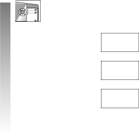
1Remove the wedge from the underside of the base unit. Press on the tabs and pull the wedge away from the phone.
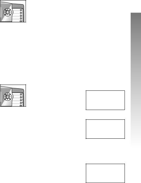
2Remove the battery compartment screw with a small Phillips head screwdriver.
3Pull on the tab to remove the battery compartment cover.
4Insert a 9V battery (purchased separately) following the polarity diagram inside the battery compartment.
5Replace the battery compartment cover and the screw.
6Reattach the wedge to the base unit by sliding the tabs into the holes. Snap the wedge onto the base.
QUICK START GUIDE
Four-Line Intercom
Speakerphone 945
Table/Desk Installation
For best results, follow the directions in “Battery Installation” above, before installing the phone.
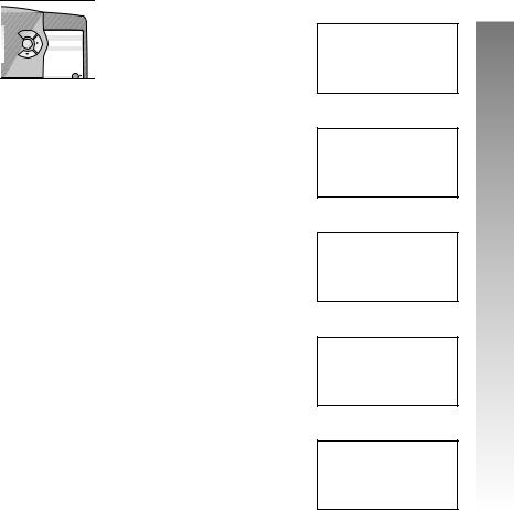
1 Connect the telephone line cords to the telephone as shown in the appropriate illustration below.
• Four One-Line Jacks (To use this installation option, you’ll need to purchase two two-line adapters. Adapters are available at retail stores or by calling 1 800 222–3111.)
Modular telephone jacks
Modular
Lines 3 and 4
telephone jacks Lines 1 and 2
Two-line adapters
Telephone line cords
L3/L4 jack 
 L1/L2 jack
•Two Two-Line Jacks
Modular |
Modular telephone |
telephone jack |
jack Lines 1 and 2 |
Lines 3 and 4 |
|
|
Telephone |
|
line cords |
L3/L4 jack 
 L1/L2 jack
2Connect the handset cord.
Plug one end of the coiled handset cord into the jack on the left side of the phone. Plug the other end into the handset and hang up.
Two seven-foot line cords
Handset
Eight-inch line cord
Base Unit
Coiled handset cord
Power adapter
Tools Needed
You will also need a small Phillips head screw driver to install your phone.
2

This 945 telephone is fully compatible with any AT&T Four-Line Intercom Speakerphone 984 or 974 units you may have installed. You can use a total of 16 945/974/984 units together as extensions in your phone system.
This 945 telephone is also compatible with any AT&T 964/955/944 phones you have previously installed. This 945 telephone is NOT compatible with any 843, 853, 854, 874, or 954 telephones you may have previously installed.
NOTE: If you have one or more 964, 955, or 944 phone(s) installed in the same phone system with this 945 telephone, you can only have 12 extensions and 15 telephone lines in the phone system.
•You must have a modular telephone jack and an electrical outlet not controlled by a wall switch near where you’re installing the phone. The total length of telephone wiring used in this system MUST NOT be more than 600 feet. In some cases a Z800A filter can
be used in a phone system with more than 600 feet of wire. AT&T highly recommends that a Z800A filter be installed by a professional. AT&T CANNOT guarantee that this telephone will work with such a filter, and IS NOT responsible for such installations. A Z800A filter can be obtained by calling
800 222-3111.
•Identify the number of phone lines you’ll use.
•Plan the layout of your phone system.
•All connected phones must have the same Line 1 phone number for the Intercom and Page features to work.
Every individual phone in your telephone system MUST be assigned a unique extension number for the Intercom feature to work. All system phones will sound an error tone until you assign separate extension numbers to each unit. For directions see "Assign an Extension Number to Your Phone" on page 21 of this manual for directions.
•Decide if you want a private line. A private line does not appear on all connected phones.
•Choose your setting for each feature. You will need to program the features after installation (see “Programmable Features List” beginning on page 6 for a brief description of the features. See the FEATURE SETUP section beginning on page 18 for programming instructions.)
BEFOREYOU BEGIN
3

BEFOREYOU BEGIN
DSL Users
Installation of a DSL splitter and an AT&T Z800A filter is required to use the advanced features of this telephone if you have DSL (Digital Subscriber Line) service.
Set-Up for DSL Users
If you are a DSL (Digital Subscriber Line) customer, you may experience interference with the advanced features of this telephone. Certain features of this phone (e.g., intercom, hold, line privacy, etc.) work by sending a data signal using Line 1. This data signal is sent at some of the same frequencies as those used by your DSL service. Microfilters are used to block the high frequency DSL signals from being transmitted through and interfering with your telephones. These same microfilters that may have been installed for your DSL service will also block the data signals between your system phones . Therefore, some features of this phone may not work properly when DSL filters are installed in your building. This problem can occur even if the DSL line is not one of the lines used by the phone system. If you use the microfilters that your DSL service provider may have supplied when you activated DSL service with this phone, some of the phone features will not work. Once the DSL splitter (described below) is installed, you will no longer experience interference.
Installation, by your DSL service provider or other professional, of a DSL splitter (not a"microfilter") AND an AT&T Z800A Isolation filter as close as possible to the "protection block" or "network interface" (where the telephone line enters the house) may resolve DSL interference. (It may be necessary to use a DSL splitter intended for outdoor use.) A DSL splitter allows the data and voice signals to use the same telephone line without interfering with each other. An AT&T Z800A filter isolates the splitter from your phone system and reduces interference with the signals used by the system phones to communicate with each other.
You can obtain an AT&T Z800A filter at no charge by calling 800 2223111. You will also receive a diagram showing the proper installation of the AT&T Z800A filter with a DSL splitter, DSL modem and your system phones. AT&T cannot supply the DSL splitter.
Please contact your DSL service provider or professional contractor for details about obtaining and installing a DSL splitter. Your DSL service provider may require you to bear any installation costs. AT&T and the manufacturer of this product have no affiliation with your DSL provider
and the type or quality of services they offer. Installation must be performed at your own expense and AT&T cannot troubleshoot or provide installation support.
4

NOTE: If your DSL service provider cannot supply a DSL splitter, it is possible to purchase an outdoor DSL splitter (such as a Corning or Allen Tel brand DSL splitter) over the Internet.
If you are a new DSL customer, your DSL service provider will likely ask you if you have more than one telephone line in your home or business. If you answer yes, your DSL service provider will probably advise you that you need a splitter. Your DSL service provider may also ask if you are installing a phone system. If you answer yes, your DSL service provider will most likely advise you that you need a splitter. In most cases, your DSL service provider will supply you with the proper splitter for your specific situation. The DSL splitter, installed properly and in conjunction with a Z800A filter, should
help overcome any interference between the DSL signal and the signals sent by your phone system.
AT&T shall not be responsible for the cost of installation, any damages, lost business, direct or indirect expenses accrued or associated with installation, or other compatibility issues which may arise as a result of using this product while you subscribe to DSL service.
Glossary
Centrex Service: A special subscriber service which may be available from your local telephone company for a fee. This 945 telephone can be used with Centrex Service.
DND: When activated the Do Not Disturb (DND) feature prevents interruptions during a call.
Line Group: A group of system phones sharing some lines within a multi-phone system.
Navigation buttons: These are the buttons used when programming your 945 phone and for scrolling through feature options (E, +, -,>,<).
Phone System: Two or more system phones combined to form an interacting system of shared lines. You can have up to 16 phones in the system.
NOTE: If you have one or more 964, 955, or 944 phone(s) installed in the same phone system with this 945 telephone, you can only have 12 extensions in the phone system.
Prime Line: This is the line on your phone you designate to be selected automatically when you lift the handset, press K, or press h.
System Phone: Any 944, 945, 955, 964, 974 or 984 phone in your phone system.
BEFOREYOU BEGIN
5

BEFOREYOU BEGIN
PROGRAMMABLE FEATURES LIST
Default settings indicated by *.
FEATURE: |
FUNCTION: |
OPTIONS: |
|
|
|
ONE TOUCH |
Choose default mode |
Intercom* or Telephone |
PREFERENCE |
for One Touch (EXT) |
|
|
buttons. |
|
|
|
|
EXTENSION NO |
Assign an extension |
11*-26 |
|
number to this phone. |
|
|
|
|
RINGER ON /OFF |
Turn the ringer on or |
On* or Off |
|
off for each line. |
|
|
|
|
RINGER TYPE |
Select a ring pattern |
Type 1*, 2, 3, 4 |
|
for this phone. |
|
|
|
|
DELAY RING |
Select desired time |
Off*, 2, 4, 6, ... 30 seconds |
|
to delay Central |
|
|
Office ring. |
|
|
|
|
AUTO-MUTE |
Turn Auto-Mute on |
On* or Off |
|
or off (sounds at this |
|
|
extension will be |
|
|
heard automatically |
|
|
when paged). |
|
|
|
|
TONE/PULSE |
Set the dial mode for |
Tone* or Pulse |
|
touch tone or dial |
|
|
pulse (rotary) dialing. |
|
|
|
|
HOLD REMINDER |
Turn the audible |
On* or Off |
|
reminder that a call |
|
|
at this extension |
|
|
is on hold on or off. |
|
|
|
|
TIME/DATE |
Set the time and date. |
01:00 AM 01/01 Sunday* |
|
|
|
LINE USAGE |
Turn Line Usage on |
On* or Off |
|
or off for each line. |
|
NOTE: One ring is equal to about six seconds, two rings equals twelve seconds, and so on.
6
PROGRAMMABLE FEATURES LIST
Default settings indicated by *.
FEATURE: |
FUNCTION: |
OPTIONS: |
|
|
|
PRIME LINE |
Assign a line on this |
Line 1*, 2, 3, 4 |
|
phone to be selected |
|
|
automatically when |
|
|
you lift the handset, |
|
|
press K, or |
|
|
press h. |
|
|
|
|
AUTOMATIC |
Choose default mode |
Speakerphone* or |
MODE |
for calls connected |
Headset |
|
with the handset in |
|
|
the cradle. |
|
|
|
|
SCROLL RATE |
Set the scrolling |
Very Slow, Slow, Medium* |
|
speed for Rapid |
Fast, or Very Fast |
|
Scroll. |
|
|
|
|
LCD BACKLIGHT |
Turn the screen |
On* or Off |
|
display backlight |
|
|
on or off. |
|
|
|
|
RESET ALL |
Return all features |
(Defaults) |
|
to default settings. |
|
|
|
|
LINE GROUP |
Assign your phone |
Line Group 4*-15 or |
|
to a Line Group. |
PRV (private) |
|
|
|
CONSOLE |
Specify whether your |
On or Off* |
|
phone is the Centrex |
|
|
Console phone for |
|
|
your phone system. |
|
|
|
|
CSL DELAY RING |
Set the time to delay |
Off*, 2, 4, 6, ... 30 seconds |
|
ring for Centrex |
|
|
Console phone. |
|
|
|
|
LANGUAGE |
Select the language for |
English*, Espanol, or |
|
screen displays. |
Français |
NOTE: One ring is equal to about six seconds, two rings equals twelve seconds, and so on.
BEFOREYOU BEGIN
7

BEFOREYOU BEGIN
Audible Signals
WHENYOU HEAR: |
IT MEANS: |
|
|
A RAPID DOUBLE-RING |
You have an incoming intercom call. |
PATTERN, REPEATING |
|
|
|
A LONG SINGLE RING, |
You have an incoming transferred call. |
REPEATING |
|
|
|
A SHORT SINGLE RING, |
The extension number you just |
REPEATING |
programmed has already been assigned. |
|
Choose another number |
|
for this extension. |
|
|
A SHORT SINGLE TONE, |
The extension you are calling is |
REPEATING |
in DND mode. |
|
|
A LONG SINGLE TONE, |
The extension you are calling is busy. |
REPEATING |
|
|
|
A VERY LONG SINGLE |
The extension you are calling is |
TONE, REPEATING |
ringing. |
|
|
8
INSTALLATION
If you are installing multiple phones in your telephone system, you must install and program one set at a time. If more than one extension
is assigned the same extension number, a repeating short ring (error ring) will sound at all extensions. Reassign extension numbers, being sure that each extension has a different number from 11 to 26 (see “Assign an Extension Number to Your Phone” on page 21).
Battery Installation
Install a 9V alkaline battery (purchased separately) in order to use some features of this telephone in the event of a power failure. If power fails and a working battery is installed, all four lines of this phone will work only to answer calls with the handset or headset, and to dial calls using the key pad and the One Touch or Redial features. No other features will work until power is restored.
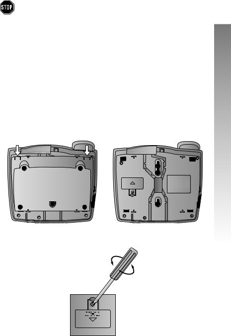
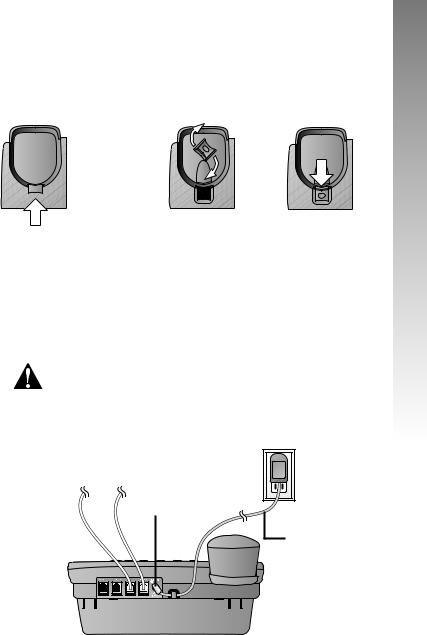
1Remove the wedge from the underside of the base unit.
Press on the tabs in the direction of the arrows and pull the wedge away from the phone.
2Remove the battery compartment screw with a small Phillips head screwdriver.
INSTALLATION
continued on page 10
9
INSTALLATION |
Battery Installation continued from page 9
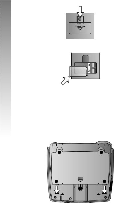
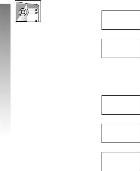
3 Pull on the tab to remove the battery compartment cover.
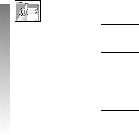
4 Insert a 9V battery (purchased separately).
5Replace the battery compartment cover and the screw.
6If you are wall mounting the phone, turn to “Wall Installation” beginning on page 13. (You will not need the wedge; store it in case you use the phone on a table or desk in the future.)
—OR—
If you are using the phone on a table or desk, reattach the wedge to the base unit by sliding the tabs into the holes as shown. Snap the wedge onto the base. Then, turn to “Table/Desk Installation” beginning on page 11.
10
Table/Desk Installation
For best results, follow the directions in “Battery Installation” on page 9 before installing the phone.
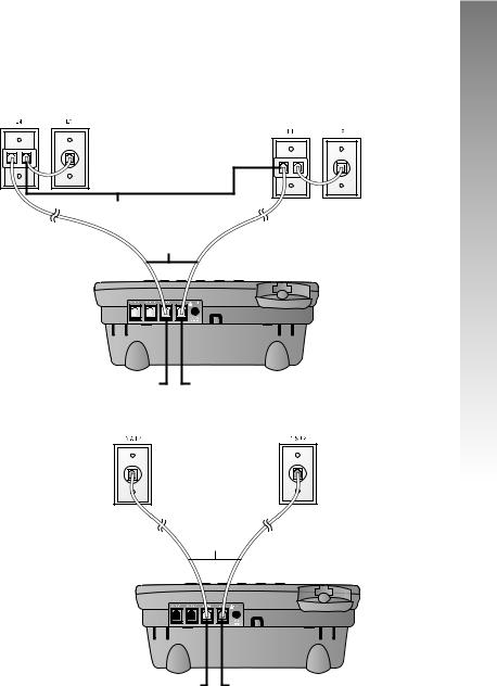
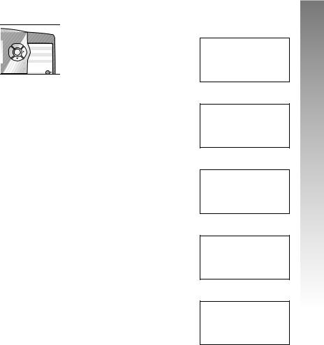
1Connect the telephone line cords to the telephone as shown in the appropriate illustration below.
•Four One-Line Jacks (To use this installation option, you’ll need to purchase two two-line adapters. Adapters are available at retail stores or by calling 1 800 222–3111.)
Modular telephone |
Modular |
|
jacks Lines 3 and 4 |
||
telephone jacks |
||
|
||
|
Lines 1 and 2 |
Two-line adapters
Telephone
line cords
INSTALLATION |
L3/L4 jack |
L1/L2 jack |
• Two Two-Line Jacks
Modular telephone jack Lines 3 and 4
Modular telephone |
jack Lines 1 and 2 |
Telephone
line cords
L3/L4 jack |
L1/L2 jack |
continued on page 12
11
INSTALLATION |
Table/Desk Installation continued from page 11
2Connect the handset cord.
Plug one end of the coiled handset cord into the jack on the left side of the phone. Plug the other end into the handset and hang up.
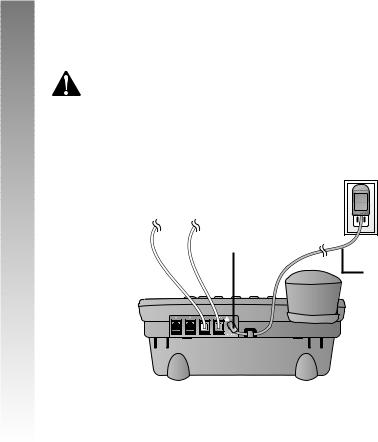
3Connect the power adapter to the telephone.
Use only the power adapter provided with this product. To obtain a replacement, call 1 800 222–3111.
Plug one end of the power adapter into the jack labeled POWER on the back of the phone. Plug the other end into a standard electrical outlet not controlled by a wall switch.
Standard
Electrical
Outlet
POWER jack
Power adapter
4Check for dial tone.
Lift the handset and listen for a dial tone. If you cannot hear a dial tone, turn to IN CASE OF DIFFICULTY beginning on page 87.
5Initialization.
If no battery is installed when you connect the power cord, the phone runs a quick self-test and the screen displays Initializing.. for about three seconds.
NOTE: The phone will run through this same initialization any time it is reconnected to AC power if a charged battery is not installed (for example, after a power failure or when the unit has been unplugged).
12
Wall Installation
For best results, follow the directions in “Battery Installation” on page 9 before installing the phone.
1If the wedge is still attached to the underside of the base unit, follow Step 1 in “Battery Installation” on page 9 to remove the wedge.
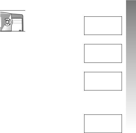
2Reverse the handset tab.
Hold down the switchhook, then pull out the handset tab and rotate it 180 degrees. Push the handset tab down into the grooves so it settles into position.
 Switchhook
 Handset tab
3Connect the telephone line cords to the telephone.
Please refer to the line cord connection instructions in Step 1 of “Table/Desk Installation” on page 11.
4Connect the handset cord.
Plug one end of the coiled handset cord into the jack on the left side of the phone. Plug the other end into the handset and hang up.
5Connect the power adapter to the telephone.
Use only the power adapter provided with this product. To obtain a replacement, call 1 800 222–3111.
Plug one end of the power adapter into the jack labeled POWER on the back of the phone. Plug the power adapter into a standard electrical outlet not controlled by a wall switch.
Standard
Electrical
Outlet
POWER jack
Power adapter
continued on page 14
INSTALLATION |
13
INSTALLATION |
Wall Installation continued from page 13
6Check for dial tone.
Lift the handset and listen for a dial tone. If you cannot hear a dial tone, turn to IN CASE OF DIFFICULTY beginning on page 87.
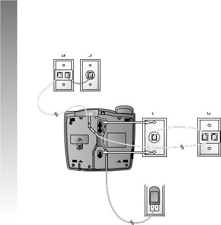
7Mount the phone on the wall.
• Four One-Line Jacks
Modular telephone jacks
Lines 3 and 4
Modular telephone Jacks
Lines 1 and 2
Power
adapter  Standard
  electrical outlet
14
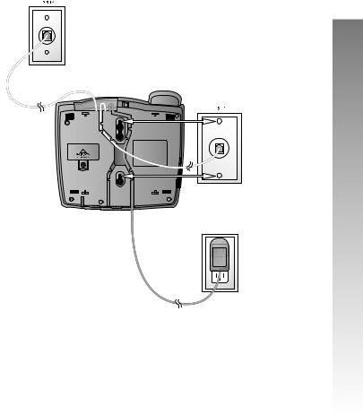
•Two Two-Line Jacks
Modular |
telephone jack |
Lines 3 and 4 |
Modular telephone jack Lines 1 and 2
Power
adapter Standard electrical
outlet
8Initialization.
If no battery is installed when you connect the power cord, the phone runs a quick self-test and the screen displays Initializing.. for about three seconds.
NOTE: The phone will run through this same initialization any time it is reconnected to AC power if a charged battery is not installed (for example, after a power failure or when the unit has been unplugged).
INSTALLATION
15
INSTALLATION |
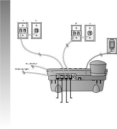
Convenience Ports
If you want to connect another device (such as a modem or fax machine) to the wall jack, you can use the jacks on the phone labeled AUX. These convenience ports use Lines 3 and 4; a call picked up on Line 3 or 4 at another extension may interrupt fax, modem, or message transmission.
•Four One-Line Jacks
Modular telephone jacks Lines 3
and 4 with two-line adapter
Modular telephone jacks |
Lines 1 and 2 with |
two-line adapter |
Standard |
electrical |
outlet |
Power adapter
AUX L4 jack |
AUX L3 jack |
L1/L2 jack |
L3/L4 jack
16
•Two Two-Line Jacks
Modular |
Modular |
|
telephone jack |
||
telephone jack |
||
Lines 3 and 4 |
||
Lines 1 and 2 |
||
|
Standard electrical outlet
Power adapter
AUX L4 jack AUX L3 jack
L1/L2 jack |
L3/L4 jack
INSTALLATION |
17
FEATURE SETUP
FEATURE SETUP


Use the navigation buttons to program or change the feature setup.
•Press Eto activate the programming mode. The screen displays:
FEATUREHSETUP
Menu ONEHTOUCHHHHHHHx
NOTE: If you do not press a key to continue programming within 30 seconds, the telephone automatically exits the Feature Setup menu.
•When xis displayed, you can press -or + repeatedly to move through the menu.
•Press Eto choose the menu item currently displayed and view the options.
Menu Item |
|
|
|
PHONE SETTINGS |
||
|
|
|||||
Current Setting |
|
|
|
|
|
|
Feature |
|
()11 |
||||
|
|
|
EXTENSIONHNOHHHx |
|||
|
|
|
||||
|
|
|
|
|
|
|
•When ()is displayed, you can press >or < to scroll through setting choices.
•Press -to store the setting and show the next option for the feature currently displayed.
•To return to the main menu, press -or + until the screen display includes MAIN MENU or EXIT. Then, press E.
•To exit programming mode, press and hold
E.
NOTE: If the phone beeps twice, repeat the steps to program the feature.
18
|
|
Rapid Scroll |
|
You can scroll through menu items or setting choices |
|
more quickly using this feature. Press and hold the |
||
|
|
desired scroll button (+, -, >or <). The screen |
|
|
|
|
|
will scroll through your choices at the rate you program |
|
during Feature Setup. See “Set the Scroll Rate” on page |
|
43 for programming instructions.
Set One Touch Preference
Choose whether pressing an EXT button automatically initiates an intercom or One Touch call. If you want to place One Touch calls using only one button, set this feature to TELEPHONE. If you want to place intercom calls using only one button, set this feature to INTERCOM. See ONE TOUCH OPERATION beginning on page 69 and INTERCOM OPERATION beginning on page 76 for details about One Touch and intercom calls.
1 Press E. The screen displays:
|
FEATUREHSETUP |
|
|
|
|
|
ONEHTOUCHHHHHHHx |
|
|
|
|
2 Press E. The screen displays:
ONEHTOUCH
()HINTERCOM PREFERENCEHHHHHx
3Press <or >to toggle between INTERCOM and TELEPHONE.
4When the correct setting is shown, press - to save your choice. The screen displays:
ONEHTOUCH
PROGRAMHHHHHHHHx
continued on page 20
FEATURE SETUP
19
FEATURE SETUP

Set One Touch Preference continued from page 19
5 Press -until the screen the displays:
ONEHTOUCH
MAINHMENUHHHHHHx
6 Press E. The screen displays:
FEATUREHSETUP
ONEHTOUCHHHHHHHx
7Proceed to Step 2 on page 21 to set up the next feature (Extension Number)
—OR—
Press and hold Eto return to the idle screen
—OR—
Press -until the screen displays:
FEATUREHSETUP
EXITHHHHHHHHHHHx
Then press Eto return to the idle screen.
20


Assign an Extension Number to Your Phone
Every individual phone in your telephone system MUST be assigned a unique extension number for the intercom feature to work.
1 Press E. The screen displays:
FEATUREHSETUP
ONEHTOUCHHHHHHHx
2 Press -until the screen displays:
FEATUREHSETUP
PHONEHSETTINGSHx
3 Press E. The screen displays:
PHONEHSETTINGS
()H11 EXTENSIONHNOHHHx
4Press <or >until the correct extension number is shown.
5Press -to save the extension number. The screen displays:
PHONEHSETTINGS
RINGERHON/OFFHHx
NOTE: If you duplicate an extension number, you will hear a repeating short ring. Repeat Steps 1-5 and assign a different extension number (from 11 - 26).
continued on page 22
FEATURE SETUP
21
FEATURE SETUP

Assign an Extension Number toYour Phone continued from page 21
6Proceed to Step 5 on page 23 to set the next feature (Ringer On or Off)
—OR—
Press and hold Eto return to the idle screen
—OR—
Press -until the screen displays:
PHONEHSETTINGS
MAINHMENUHHHHHHx
Then, press E. The screen displays:
FEATUREHSETUP
PHONEHSETTINGSHx
Then, press -until the screen displays:
FEATUREHSETUP
EXITHHHHHHHHHHHx
Then, press Eto return to the idle screen.
22


Turn the Ringer On or Off for Each Line
1 Press E. The screen displays:
FEATUREHSETUP
ONEHTOUCHHHHHHHx
2 Press -until the screen displays:
FEATUREHSETUP
PHONEHSETTINGSHx
3 Press E. The screen displays:
PHONEHSETTINGS
EXTENSIONHNOHHHx
4 Press -until the screen displays:
PHONEHSETTINGS
RINGERHON/OFFHHx
5 Press E. The screen displays:
RINGERHON/OFF
()HOn L1HRINGERHHHHHHx
6Press <or >to toggle between On and Off for the line shown.
7Press -to save the displayed ringer setting. The screen will show the current ringer setting for the next line (L1...L4).
8Repeat Steps 6 and 7 to turn the ringer on or off for other lines at this phone.
continued on page 24
FEATURE SETUP
23
FEATURE SETUP

Turn the Ringer On or Off for Each Line continued from page 23
9When you finish setting the ringer, press -until the screen displays:
RINGERHON/OFF
DONEHHHHHHHHHHHx
10 Press E. The screen displays:
PHONEHSETTINGS
RINGERHON/OFFHHx
11Proceed to Step 4 on page 25 to set the next feature (Ringer Type)
—OR—
Press and hold Eto return to the idle screen
—OR—
Press -until the screen displays:
PHONEHSETTINGS
MAINHMENUHHHHHHx
Then, press E. The screen displays:
FEATUREHSETUP
PHONEHSETTINGSHx
Then, press -until the screen displays:
FEATUREHSETUP
EXITHHHHHHHHHHHx
Then, press Eto return to the idle screen.
24


Select the Ringer Type
You can choose a ring pattern for incoming phone calls.
NOTE: Incoming intercom calls use Ringer Type 1 and cannot be changed.
1 Press E. The screen displays:
FEATUREHSETUP
ONEHTOUCHHHHHHHx
2 Press -until the screen displays:
FEATUREHSETUP
PHONEHSETTINGSHx
3 Press E. The screen displays:
PHONEHSETTINGS
()H11 EXTENSIONHNOHHHx
4 Press -until the screen displays:
PHONEHSETTINGS
RINGERHTYPEHHHHx
5 Press E. The screen displays:
RINGERHTYPE
()HTypeH1 L1HRINGERHTYPEHx
6Press <or >to change the ringer type (Type 1 …Type 4) for the line shown.
continued on page 26
FEATURE SETUP
25
FEATURE SETUP

Select the Ringer Type continued from page 25
7Press -to save the current setting and move to the next line with its ringer type.
8Repeat Steps 6 and 7 to set ringer types for other lines on this phone (L1...L4).
9When you are finished setting the ringer type, press -until the screen displays:
RINGERHTYPE
DONEHHHHHHHHHHHx
10 Press E. The screen displays:
PHONEHSETTINGS
RINGERHTYPEHHHHx
11Press -and proceed to Step 5 on page 27 to set the next feature (Delay Ring)
—OR—
Press and hold Eto return to the idle screen
—OR—
Press -until the screen displays:
PHONEHSETTINGS
MAINHMENUHHHHHHx
Then, press E. The screen displays:
FEATUREHSETUP
EXITHHHHHHHHHHHx
Then, press Eto return to the idle screen.
26
 Loading...