

AT&T and the globe symbol are registered trademarks of AT&T Corp.licensed to Advanced American Telephones.
1
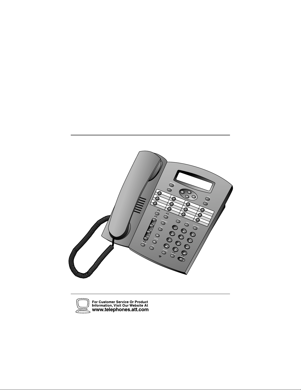
Four-Line Intercom
Speakerphone 944
1
USER’S MANUAL
Part 2
Please also read
Part 1 – Important
Product Information

BEFORE YOU BEGIN ....................... 2
Glossary ............................................... 3
Features List......................................... 4
Audible Signals .................................... 5
INSTALLATION ............................... 6
Table/Desk Installation ........................ 6
Wall Installation................................... 8
Convenience Ports ............................ 12
FEATURE SET UP .......................... 13
Set the Time/Date.............................. 14
Assign an Extension Number
to Your Phone................................ 14
Turn the Ringer On or Off
for Each Line.................................. 14
Select the Ringer Type....................... 15
Set Delay Ring ................................... 15
Turn Line Usage On or Off
for Each Line.................................. 15
Assign the Prime Line
(Line Preference) .......................... 16
Assign the Line Group
for this Phone ................................ 16
Turn Auto-Mute On or Off................. 16
Set Audio Mode.................................. 17
Set the Dial Mode.............................. 17
Set the Flash Time ............................. 17
Turn Hold Reminder On or Off ........ 17
Set Your Phone to be the Centrex
Console Phone .............................. 18
Program the Centrex Console
Delayed Ring Time......................... 18
Erase All Settings and Return
the Phone to Default Settings........ 18
TELEPHONE OPERATION ............... 19
Making or Answering a Call ............... 20
Timer .................................................. 21
Pause................................................... 21
Call Privacy......................................... 22
Do Not Disturb................................... 22
Line-in-Use Lights ............................... 23
Volume................................................ 23
Redial................................................. 23
Auto Redial........................................ 24
Hold .................................................... 24
Switch Between Lines........................ 24
Mute..................................................... 25
Flash..................................................... 25
Temporar y Tone Dialing...................... 25
Conference Calls ................................. 25
Transfer a Call..................................... 26
Low Battery Indicator ........................ 26
SPEED DIAL OPERATION............... 27
Storing a Number in
a Speed Dial Location ..................... 28
Reviewing a Speed Dial Entry ............ 28
Making a Speed Dial Call.................... 28
INTERCOM OPERATION ................. 29
Basic Intercom Operations................. 30
Making an Intercom Call with
the Handset ................................... 30
Making an Intercom Call with the
Speakerphone or Headset ............. 31
Answering an Intercom Call ............ 31
Making a Single-phone Page.............. 31
Answering a Single-phone Page ......... 31
Switching Between an Intercom
Call and a Single-phone Page......... 31
Ending an Intercom or Page Call........ 31
Paging All Phones ............................... 32
Answering a System-wide Page.......... 32
Making an Intercom
Conference Call............................. 32
Room Monitor .................................... 32
ADDING A FAX MACHINE............... 33
Using a Fax Switch............................. 33
IN CASE OF DIFFICULTY ................ 34
EXPANDING THE PHONE SYSTEM .. 36
Line Groups........................................ 36
Private Lines ....................................... 37
CENTREX OPERATION ................... 38
Setup Checklist................................... 38
Enabling the Console Phone.............. 38
Console Operation ............................. 38
Setting Ring Delay Duration................. 39
Answering a Delayed Ring.................. 39
Picking Up Another Station’s Line..... 39
INDEX ........................................... 40
CONTENTS
1

2
This 944 telephone is fully compatible with any AT&T Four-Line Intercom
Speakerphone 964 or 955 units you may have installed. You can use up
to a total of 12 944/955/964 units together as extensions on your phone
system.
• Check to be sure your box contains:
1 Telephone
1 Handset
1 Handset cord
1 Mounting base
2 Seven-foot line cords
1 Eight-inch line cord
1 Power adapter
1 Warranty insert
1 9V battery
1 User’s Manual
• You must have a modular telephone jack and an electrical outlet
not controlled by a wall switch near where you’re installing the
phone.
• The total length of telephone wiring used in this system is
important. If the total length of telephone wiring is more than
600 feet, you may need to use a special filter device. You can call
1 800 222–3111 for information about this filter. You’ll need to
contact a professional to install this filter.
• Identify the number of phone lines you’ll use.
• Plan the layout of your phone system.
• All connected phones must have the same Line 1 phone number
for the Intercom and Page features to work.
• Assign a different Intercom Extension Number (11 through 22)
to each system phone. You’ll need to do this individually at each
telephone.
• Decide if you want a private line. A private line does not appear
on all connected phones.
• Choose your setting for each feature. You will need to program
the features during installation (see “Features List”).
BEFORE YOU BEGIN

3
Glossary
Centrex Service: A special subscriber service which may be available
from your local telephone company for a fee. The 944 telephone can be
used with Centrex Service.
DND: When activated the Do Not Disturb feature prevents interruptions
during a call.
Line Group: A group of system phones sharing some lines within a
multi-phone system.
Navigation buttons: These are the buttons used when programming
your 944 phone and for scrolling through feature options (+, -, >, <,
E, S).
Phone System: Two or more 944/955/964 phones combined into an
interacting system of shared lines. You can have up to 12 phones and
up to 15 telephone lines in the system.
Prime Line: This is the line on your phone you designate to be selected
automatically when you lift the handset, press K, or press h.
System Phone: Any 944, 955 or 964 phone in your phone system.
BEFORE YOU BEGIN

4
Feature Function Setting Option(s)
TIME/DATE
EXTENSION NO
RINGER ON/OFF
RINGER TYPE
DELAY RING
LINE USAGE
PRIME LINE
LINE GROUP
AUTO-MUTE
AUDIO MODE
TONE/PULSE
FLASH TIME
HOLD REMINDER
CONSOLE
CSL DELAY RING
RESET ALL!!!
Set time and date
Assign extension number for this
phone
Turn ringer on or off for each line
Select ring pattern for this phone
Select desired time to delay
Central Office ring
Turn line usage on or off for
each line
Assign a line on this phone to be
selected automatically when you
lift the handset, press K,
or press h
Assign your phone to a Line
Group
Turn Auto-Mute on or off
(sounds at this extension will be
heard automatically when paged)
Choose default mode for calls
connected with handset in cradle
Set dial mode for touch-tone or
dial pulse (rotary) dialing
Set length of signal sent when
you press F
Turn audible reminder that a call
at this extension is on hold on
or off
Specify whether your phone is
the Centrex Console phone for
your phone system
Set time to delay ring for Centrex
Console phone
Return all settings to
default settings
01:00AM 01/01 Sunday*
11-22*
On* or Off
Type 1*,2, 3, 4
Off *, 2, 4, 6, ...30 seconds
On* or Off
Line 1*, 2, 3,4
Line Group 4*-15 or PRV
(private)
On* or Off
Speakerphone* or Headset
Tone* or Pulse
0.3 seconds - 0.9 seconds
0.7 seconds*
On* or Off
On or Off *
Off *, 2, 4, 6, ... 30 seconds
(Defaults)
Features List
NOTE: An * indicates the default setting for each feature.
NOTE: One ring is equal to about six seconds, two rings equals twelve
seconds, and so on.
BEFORE YOU BEGIN

5
BEFORE YOU BEGIN
Audible Signals
You have an incoming intercom call.
You have an incoming transferred call.
The extension number you just programmed has
already been assigned. Choose another number for
this extension.
The extension you are calling is in DND mode.
The extension you are calling is busy.
A rapid double-ring pattern,
repeating
Long single ring, repeating
Short single ring, repeating
Short single tone, repeating
Long single tone, repeating
When you hear: It means:
6
INSTALLATION
NOTE: If you are installing multiple phones in your telephone system,
you must install and program one set at a time. If more than one
extension is assigned the same extension number, a repeating short ring
(error ring) will sound at all extensions. Reassign extension numbers,
being sure that each extension has a different number from 11 to 22
(see “Assign an Extension Number to Your Phone” in FEATURE SET UP).
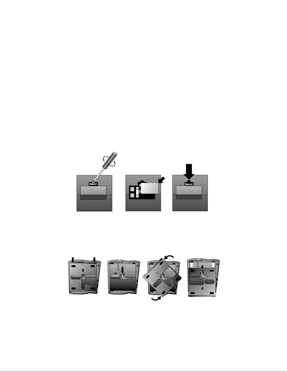
Table/Desk Installation
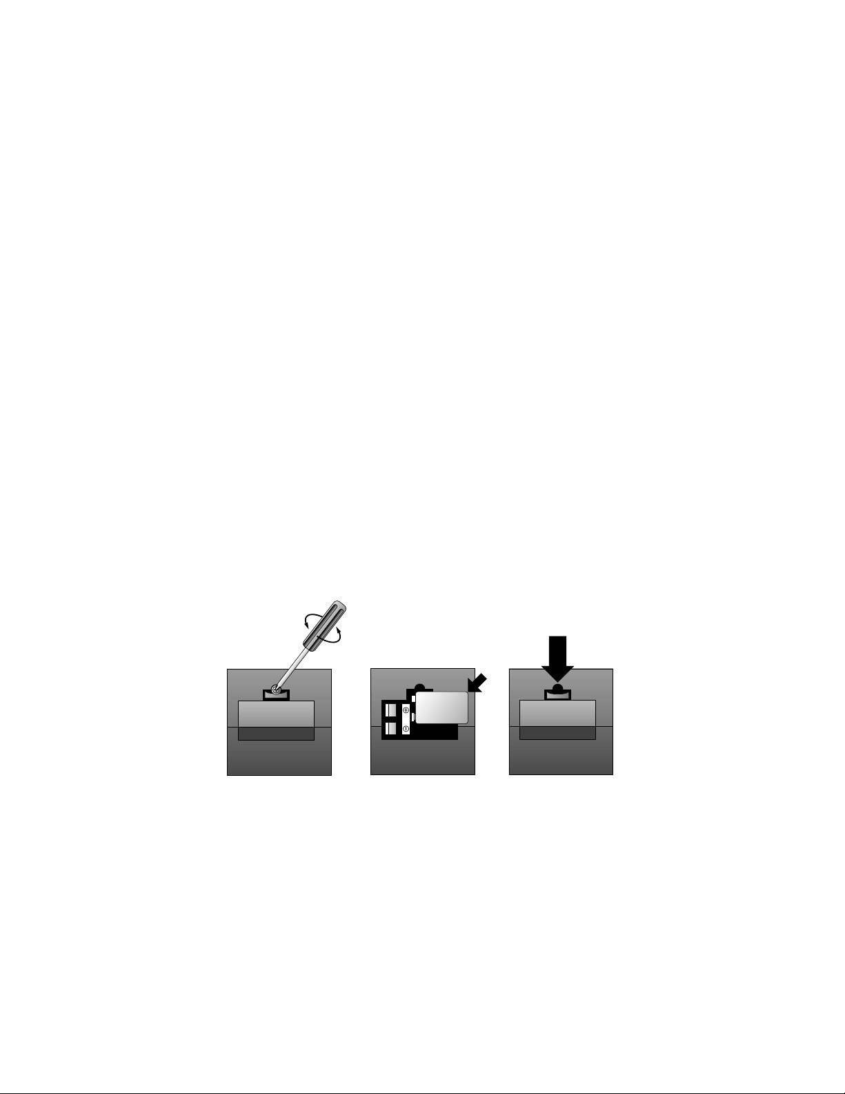
1 Install one 9V battery.
• Press in on the tabs and remove the telephone base.
• Use a small Phillips head screwdriver to remove the screw
and open the battery door.
• Insert the 9V battery (included), and replace the screw to
close the battery door.
• Replace the telephone base.
NOTE: The battery retains telephone memory in the event of a power
failure. If power fails and a working battery is installed, all four lines
of this phone will work only to answer calls with the handset or headset,
and dial calls using the key pad and the Speed Dial or Redial features.
No other features will work until power is restored.
7
INSTALLATION
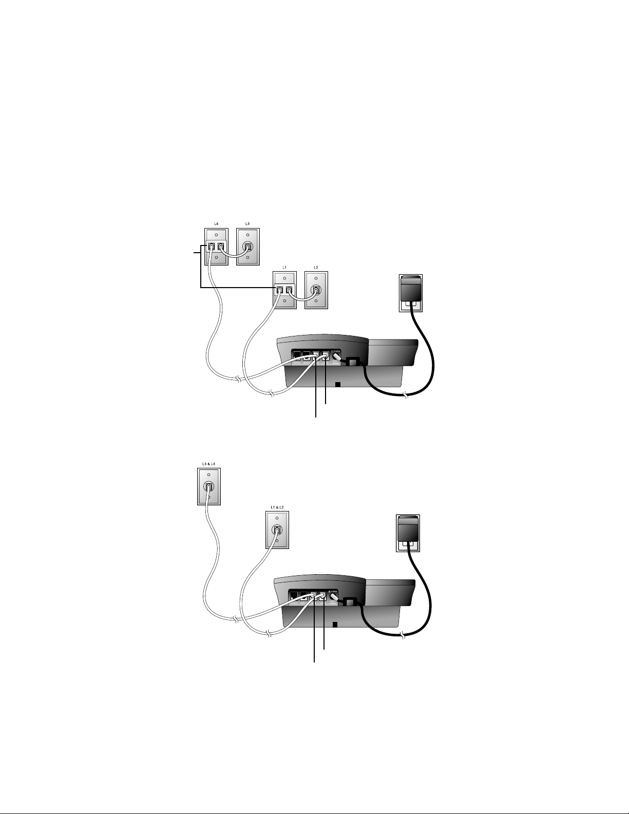
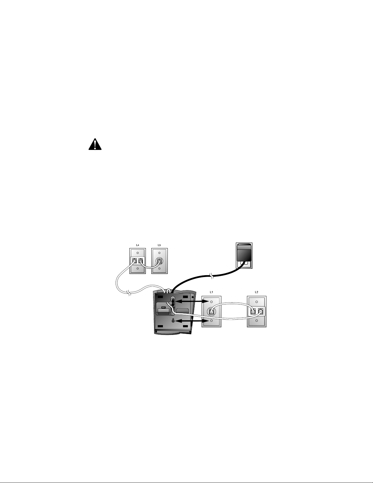
2 Connect the telephone line cords to the telephone.
• Four One-Line Jacks (To use this installation option, you’ll
need to purchase two two-line adapters. Adapters are available
at retail stores or by calling 1 800 222–3111.)
Two-line
Adapters
Telephone
Line Cords
Modular
Telephone Jacks
Lines 3 and 4
Modular
Telephone Jacks
Lines 1 and 2
Standard
Electrical
Outlet
Power Cord
Telephone Jack L1/L2
Telephone Jack L3/L4
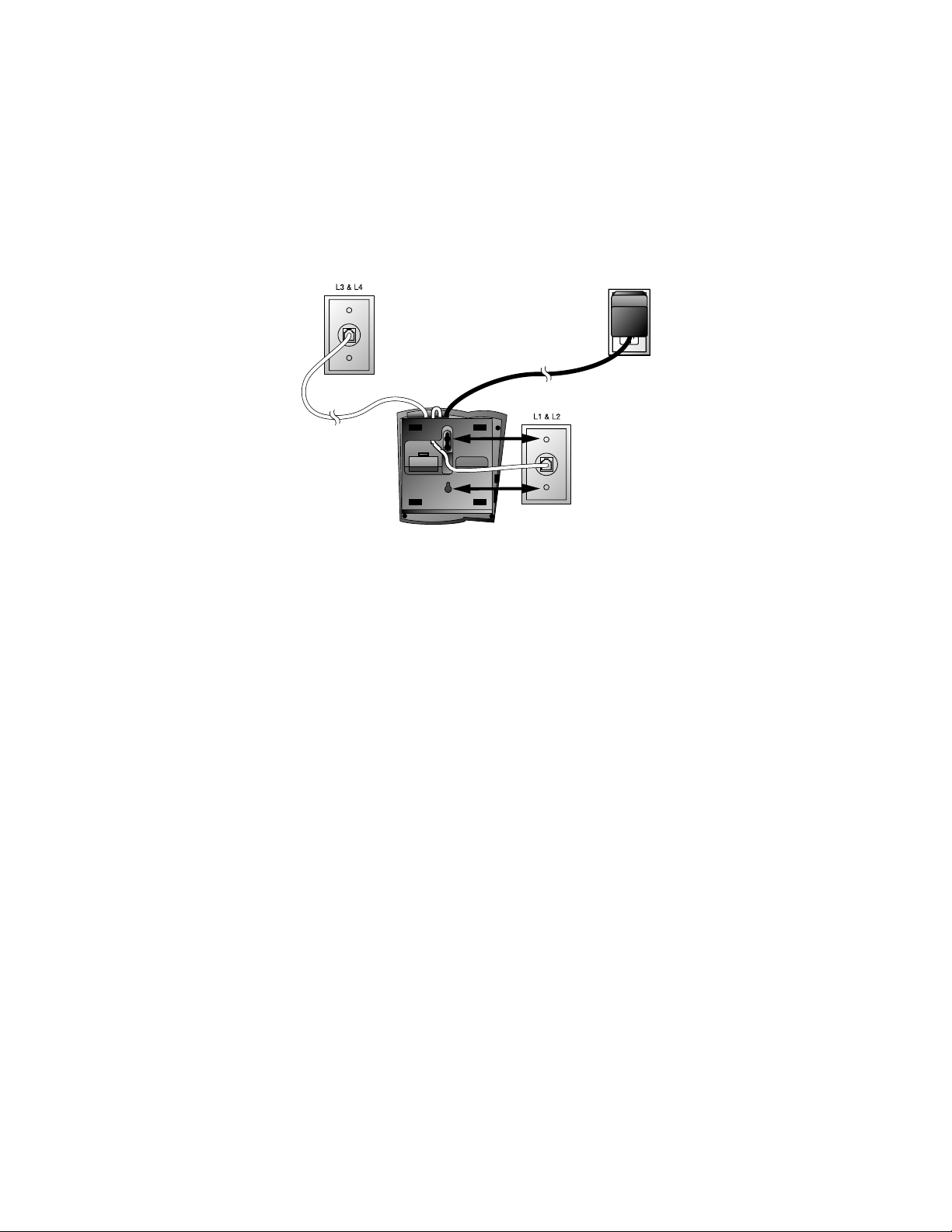
• Two Two-Line Jacks
Telephone
Line Cords
Modular
Telephone Jack
Lines 3 and 4
Modular
Telephone Jack
Lines 1 and 2
Standard
Electrical
Outlet
Power Cord
Telephone Jack L1/L2
Telephone Jack L3/L4
8
INSTALLATION
Wall Installation
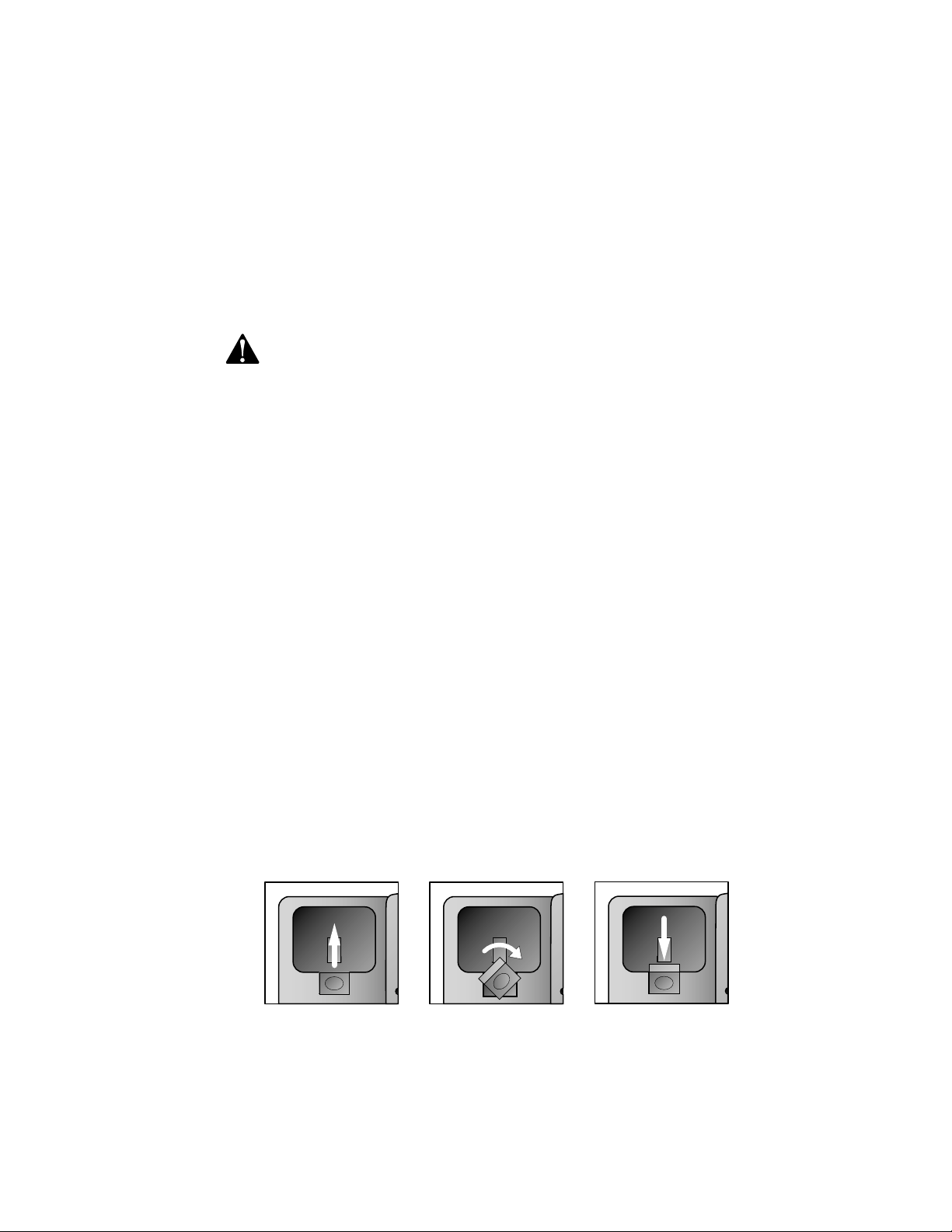
1 Reverse the handset tab.
Hold down the switchhook, then pull the tab out and rotate it
180 degrees. Push the tab down into the grooves so it settles
into position.
3 Connect the handset cord.
Plug one end of the coiled handset cord into the jack on the left side
of the phone. Plug the other end into the handset, and hang up.
4 Connect the power adapter.
Use only the power adapter provided with this product. To obtain
a replacement, call 1 800 222–3111.
Plug one end of the power adapter into the jack labeled POWER
on the back of the phone. Plug the other end into a standard
electrical outlet not controlled by a wall switch.
NOTE: The screen will display POWERFAIL the first time you plug in the
phone. Press any key to clear the screen.
5 Check for dial tone.
Lift the handset and listen for a dial tone. If you cannot hear a dial
tone, turn to IN CASE OF DIFFICULTY.
6 Initialization.
As soon as you connect the power cord, the phone runs a quick
self-test and the screen displays Initializing.. for about seven
seconds. When the test is complete, the phone enters an initial
setup mode and the screen displays press PROG to setup
your phone. See FEATURE SET UP beginning on page 13.
NOTE: The phone will run through this same initialization anytime it
is reconnected to AC power (i.e., after a power failure or when the unit
has been unplugged).
9
INSTALLATION
2 Install one 9V battery.
• Press in on the tabs and remove the telephone base.
• Use a small Phillips head screwdriver to remove the screw
and open the battery door.
• Insert the 9V battery (included), and replace the screw to
close the battery door.
• Replace the telephone base.
NOTE: The battery retains telephone memory in the event of a power
failure. If power fails and a working battery is installed, all four lines
of this phone will work only to answer calls with the handset or headset,
and dial calls using the keypad and the Speed Dial or Redial features.
No other features will work until power is restored.
3 Connect the telephone line cords to the telephone.
Please refer to line cord connection instructions in Step 2 of
“Table/Desk Installation’ on page 7.
4 Turn the base, as shown, and attach it to the bottom of
the phone.
10
5 Connect the handset cord.
Plug one end of the coiled handset cord into the jack on the
left side of the phone. Plug the other end into the handset,
and hang up.
6 Connect the power adapter to the telephone.
Use only the power adapter provided with this product. To obtain
a replacement, call 1 800 222–3111.
Plug one end of the power adapter into the jack labeled POWER
on the back of the phone.
NOTE: The screen will display POWERFAIL the first time you plug in the
phone. Press any key to clear the screen.
7 Check for dial tone.
Lift the handset and listen for a dial tone. If you cannot hear a dial
tone, turn to IN CASE OF DIFFICULTY.
8 Mount the phone on the wall.
• Four One-Line Jacks
INSTALLATION
Modular
Telephone Jacks
Lines 3 and 4
Modular Telephone Jacks
Lines 1 and 2
Standard
Electrical
Outlet
Power Cord
11
Modular
Telephone Jack
Lines 3 and 4
Modular
Telephone Jack
Lines 1 and 2
Standard
Electrical
Outlet
Power Cord
INSTALLATION
9 Plug the power adapter into a standard electrical outlet not
controlled by a wall switch.
10 Initialization.
As soon as you connect the power cord, the phone runs a quick
self-test and the screen displays Initializing.. for about seven
seconds. When the test is complete, the phone enters an initial
setup mode and the screen displays press PROG to setup
your phone. See FEATURE SET UP beginning on page 13.
NOTE: The phone will run through this same initialization anytime it
is reconnected to AC power (i.e., after a power failure or when the unit
has been unplugged).
• Two Two-Line Jacks
12
INSTALLATION
• Two Two-Line Jacks
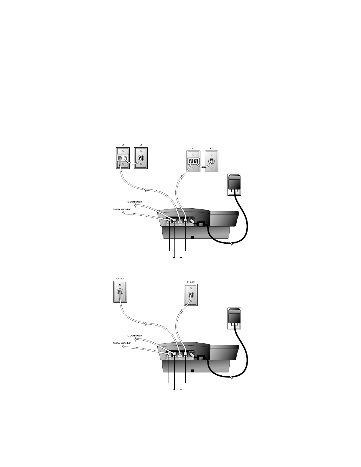
Convenience Ports
If you want to connect another device (such as a modem or fax machine)
to the wall jack, you can use the jacks on the phone labeled AUX. These
convenience ports use Lines 3 and 4; a call picked up on Line 3 or 4 at
another extension may interrupt fax, modem, or message transmission.
Modular
Telephone Jack
Lines 3 and 4
Modular
Telephone Jack
Lines 1 and 2
Standard
Electrical
Outlet
Power Cord
Telephone Jack L1/L2
Telephone Jack L3/L4
Telephone Jack Aux L4
Telephone Jack Aux L3
• Four One-Line Jacks
Modular
Telephone
Jacks
Lines 3 and
4 with
Two-line
Adapter
Modular Telephone Jacks
Lines 1 and 2 with
Two-line Adapter
Standard
Electrical
Outlet
Power Cord
Telephone Jack L1/L2
Telephone Jack L3/L4
Telephone Jack Aux L4
Telephone Jack Aux L3

13
FEATURE SET UP
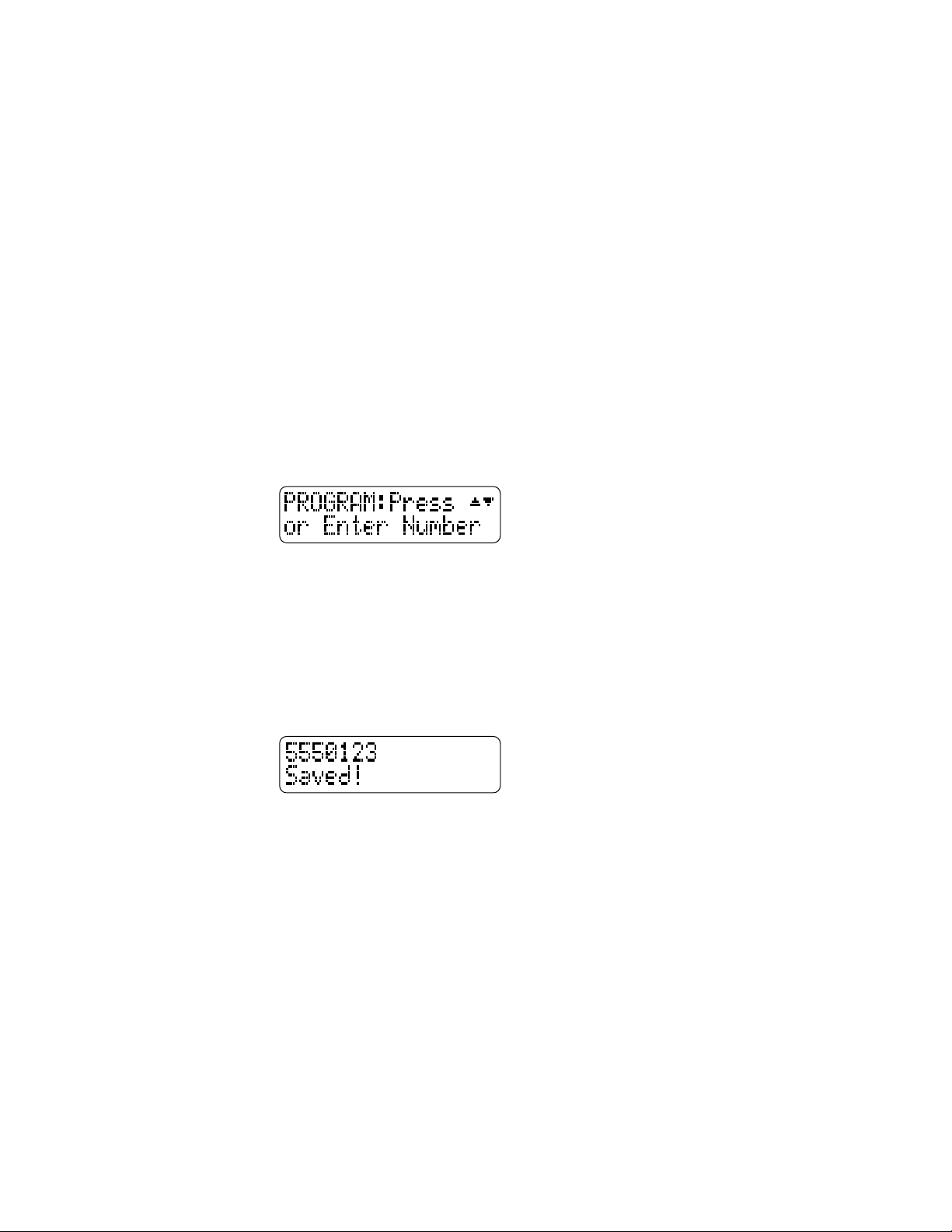
Use the Navigation buttons to program or change the features setup.
• Press G to enter the programming mode. The screen displays:
NOTE: If you do not press a key to continue programming within
20 seconds, the telephone automatically exits the programming mode.
• Press - or + repeatedly to move through the list of options.
• Press > to choose the option currently displayed.
• Press S to store your selections and return to the ‘home screen’
for the feature currently displayed.
You can set up one feature at a time or you can set up a feature and then
move on to set up another feature. After you change one feature,press
+ or - to select another feature. When you are finished with features
setup, press E to exit programming mode.
NOTE: After a feature is successfully programmed, the phone beeps
once. If the phone beeps twice, repeat the steps to set up the feature.
Feature
Options
Store your
selection and
move to next
feature
Scroll through
options
Confirm
option choice
Exit programming
mode
Enter
programming
mode

14
FEATURE SET UP
Set the Time/Date
1 Press G.
2 Press - until the screen displays TIME/DATE.
3 Press >,The screen displays the current setting.
4 Press - or + to change the hour setting.
5 Press S to store the hour setting.
6 Press - or + to change the minutes setting.
7 Press S to store the minutes setting.
8 Press - or + to select AM or PM.
9 Press S to store the setting.
10 Press - or + to change the month.
11 Press S to store the setting.
12 Press - or + to change the day of the month.
13 Press S to store the setting. The screen displays the
current day of the week setting.
14 Press - or + to change the day of the week.
15 Press S to store the setting.
Assign an Extension Number to Your Phone
1 Press G.
2 Press - until the screen displays EXTENSION NO, then press >.
3 Press - or + to select the desired extension number (from 11 to 22).
4 Press S to store your selection.
NOTE: If you duplicate an extension number, you will hear a repeating
short ring. Repeat Steps 1-4 and assign a different number (from 11 to 22).
Turn the Ringer On or Off for Each Line
1 Press G.
2 Press - until the screen displays RINGER ON/OFF, then press >.
3 Press - or + until the screen displays the desired line number,
then press >. The screen displays the current setting for that line.
4 Press - or + to change the setting.
5 Press S to store your selection.
6 Repeat Steps 1-5 to change the ringer setting for additional lines.

15
FEATURE SET UP
Select the Ringer Type
1 Press G.
2 Press - until the screen displays RINGER TYPE, then press >.
3 Press - or + to select the desired setting. You will hear a sample
of each ringer type as you move through the settings.
4 Press S to store your selection.
Set Delay Ring
Set the length of time before incoming calls will ring at this extension.
1 Press G.
2 Press - until the screen displays DELAY RING, then press >.
3 Press - or + to select the desired setting. (One ring is about
six seconds.)
4 Press S to store your selection.
Turn Line Usage On or Off for Each Line
If you are not using all four phone lines, you need to turn off Line Usage
for the unused lines. If you expand to a third or fourth line, turn Line
Usage back on.
You may also restrict the use of certain lines on this phone to intercom
and paging only, by turning off Line Usage for each line to be restricted.
When Line Usage is turned off, that line cannot be used to answer
incoming calls or to make outgoing or transfer calls.
1 Press G.
2 Press - until the screen displays LINE USAGE, then press >.
3 Press - or + until the screen displays the desired line number,
then press >.
4 Press - or + to change the setting.
5 Press S to store your selection.
6 Repeat Steps 1-5 to change the Line Usage status for additional
lines.

16
FEATURE SET UP
Assign the Prime Line (Line Preference)
1 Press G.
2 Press - until the screen displays PRIME LINE, then press >.
3 Press - or + to select the desired setting.
4 Press S to store your selection.
Assign the Line Group for this Phone
1 Press G.
2 Press - until the screen displays LINE GROUP, then press >.
3 Press - or + to select the desired setting.
4 Press S to store your selection.
Turn Auto-Mute On or Off
Choose whether sounds at this extension will be heard automatically in
response to a page (Auto-Mute Off) or only when M is pressed.
Auto-Mute Off permits hands-free conversation and room monitoring;
Auto-Mute On protects privacy.
1 Press G.
2 Press - until the screen displays AUTO MUTE, then press >.
3 Press - or + to change the setting.
4 Press S to store your selection.

17
FEATURE SET UP
17
Set Audio Mode
Choose the mode (speakerphone or headset) the phone will automatically
use to make and answer calls when the handset is in the cradle.
1 Press G.
2 Press - until the screen displays AUDIO MODE, then press >.
3 Press - or + to change the setting.
4 Press S to store your selection.
NOTE: If you have programmed headset as the default mode but the
headset is not plugged in, the phone will switch to speakerphone.
Set the Dial Mode
1 Press G.
2 Press - until the screen displays TONE/PULSE, then press >.
3 Press - or + to change the setting.
4 Press S to store your selection.
Set the Flash Time
NOTE: If you are using this phone within the United States, there is no
need to change the Flash Time from the default setting (0.7 seconds).
1 Press G.
2 Press - until the screen displays FLASH TIME, then press >.
3 Press - or + to select the desired setting.
4 Press S to store your selection.
Turn Hold Reminder On or Off
1 Press G.
2 Press - until the screen displays HOLD REMINDER, then press >.
3 Press - or + to change the setting.
4 Press S to store your selection.

You will need to program the next two features if this phone is the
designated Console Phone for your Centrex system:
Set Your Phone to be the Centrex Console Phone
NOTE: This feature is for use with Centrex systems only.
1 Press G.
2 Press - until the screen displays CONSOLE, then press >.
3 Press - or + to change the setting.
4 Press S to confirm your selection.
Program the Centrex Console Delayed Ring Time
NOTE: This feature is for use with Centrex systems only.
Set the length of time the phone will route your calls to the Centrex
Console phone. One ring is about six seconds.
1 Press G.
2 Press - until the screen displays CSL DELAY RING, then
press >.
3 Press - or + to select the desired setting.
4 Press S to confirm your selection.
Erase All Settings and Return the Phone to Default
Settings
1 Press G.
2 Press - until the screen displays RESET ALL.
3 Press >. The screen displays:
4 Press 7 within three seconds to confirm the RESET ALL command.
The screen displays:
18
FEATURE SET UP

19
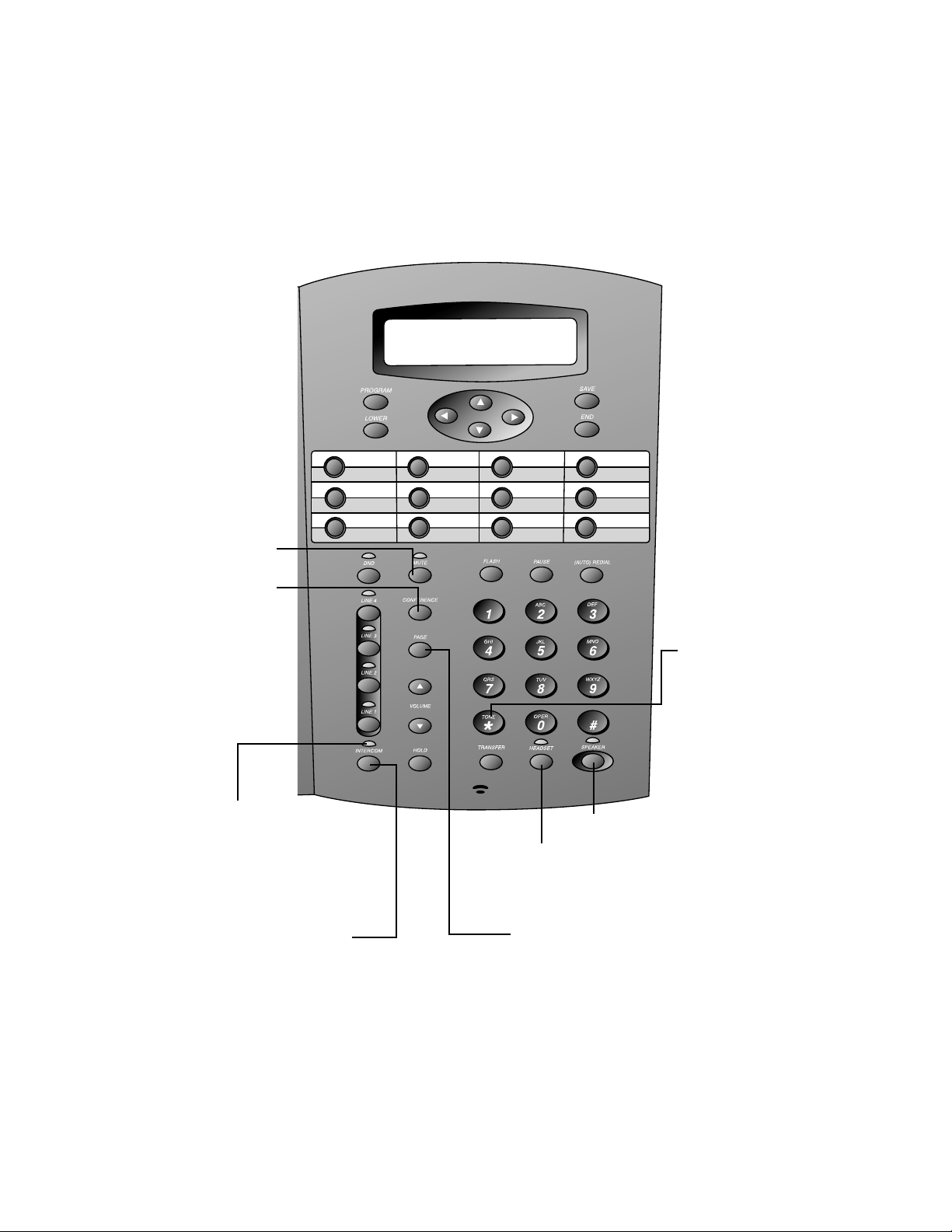
TELEPHONE OPERATION
Activate
custom-calling
services
Activate temporary tone dialing
Activate
hands-free
calling with
speakerphone
Activate
hands-free
calling with
headset
Lit: headset in use
Flashing slowly: waiting to
place Auto Redial call
Flashing quickly: dialing
Auto Redial call
Lit: speakerphone in use
Flashing slowly: waiting to
place Auto Redial call
Flashing quickly: dialing
Auto Redial call
Redirect an incoming call
to any system phone
Initiate a three-party call
Put a caller on hold
Adjust volume of ringer,
handset, speakerphone,
and headset
Line-in-use lights
Line
buttons
Prevents interruptions during a call
Mute the microphone
Redial last
number called
– OR –
Automatically
redial a
number when
the line you’re
calling is busy
Insert a
three-second
pause in
the dialing
sequence

20
NOTE: When you make a call, the phone selects the Prime Line you
programmed. When you answer a call, the phone automatically selects
the ringing line.
Making or Answering a Call
NOTE: This phone will automatically make and answer calls in the mode
(speakerphone or headset) you programmed (see “Set Automatic Audio
Mode” in FEATURE SETUP). Follow the directions below to choose a mode
manually. If the phone is in use on one line, any other calls made
or answered will use the same mode already in use.
NOTE: If you dial a phone number longer than 15 digits, the screen
will display only the last 13 digits.
Handset
To make a call, lift the handset and dial the call.
To answer a call, lift the handset. Replace the handset to end the call.
To override automatic line selection, lift the handset,then press and
release a LINE button
— OR —
Press the LINE button for the line you wish to select, then lift the handset.
Speakerphone
To make a call, press and release the desired LINE button or K.
The SPEAKER light goes on. Wait for a dial tone, then dial the call.
To answer a call, press K or press the LINE button of the incoming
call. Press K again to end the call.
NOTE: If headset is programmed as the default mode (see “Set
Automatic Audio Mode” in FEATURE SETUP), you must press K to
activate the speakerphone.
Headset
You can use this phone hands-free when you install a 2.5mm headset.
Headsets are available for purchase in retail stores (comcode #108041732)
or by calling 1 800 222-3111.
Make sure the headset is plugged into the headset jack located to the left
of the handset jack on the left side of the telephone base. You will hear a
double-beep if you press h and the headset is not plugged in.
NOTE: If headset is programmed as the default mode, (see “Set
Automatic Audio Mode” in FEATURE SET UP) but the headset is not
plugged in, the phone will switch to speakerphone.
TELEPHONE OPERATION

21
TELEPHONE OPERATION
To make a call, press and release h or press the desired LINE
button and then press h. The HEADSET light goes on. Wait for a
dial tone, then dial the call.
To answer a call, press h. Press h again to end the call.
NOTE: If speakerphone is programmed as the default mode (See “Set
Automatic Audio Mode” in FEATURE SET UP), you must press h
to activate the headset.
Switching Modes
To switch from handset to headset or speakerphone, press h or
K, then replace the handset (for headset, headset must be plugged in).
To switch from speakerphone to handset, lift the handset. (Do not
press K or the call will be disconnected.)
To switch from headset to handset (when handset is in the cradle),
lift the handset.
To switch from headset to handset (when handset is off-hook), press
h again.
To switch from headset to speakerphone (when handset is in the
cradle), press K.
To switch from headset to speakerphone (when handset is off-hook),
press K and replace the handset.
To switch from speakerphone to headset, insert the headset plug into
the jack, and press h.
To override automatic line selection, press and release a LINE button
(this activates the speakerphone or headset, whichever is programmed as
the default mode).
Timer
When you make or answer a call, the timer automatically starts. The screen
displays the elapsed time in minutes and seconds for the first hour (up to
59:59 ) and then begins again. The timer stops automatically when you
hang up and the recorded time is displayed for about 10 seconds.
The timer also stops when you place a call on hold and resets when you
release hold.
Pause
While dialing a call press P where you want to insert a three-second
pause in the dialing sequence. This is useful if you are dialing a long-distance
access code and the long-distance carrier requires a pause between the
access code and the telephone number.

22
TELEPHONE OPERATION
Call Privacy
To ensure call privacy,the phone allows only one set at a time to use a line.
Canceling Call Privacy
During the call, press the LINE button for the call. You’ll hear a short beep.
Others can now join the call.
Restoring Call Privacy
Press the LINE button again during the call. You’ll hear a double-beep.
The other phones will be dropped from the call.
NOTE: Call privacy is automatically restored when you end the call.
NOTE: When a non-system phone answers a call, any other system phone
can pick up the call by pressing the LINE button. Once a system phone
picks up the call, Call Privacy is activated and no other system phones
can listen to the call unless Call Privacy is canceled, but non-system
phones which share that line can still join the call.
Do Not Disturb
When your phone is off-hook (i.e., you are on a call) you will hear a low
volume ring when you receive an intercom call. In order to prevent even
this audible signal, activate the Do Not Disturb feature. When you activate
this feature you will not hear paging tones, voice paging, or incoming call
rings. Instead, the LINE light flashes and the INTERCOM light goes on
to signal an incoming call or page. If you receive an intercom call, the
INTERCOM light flashes, and the intercom number calling you appears on
the display.
1 Press N to prevent interruptions. The DND light goes on and
the screen display includes DND.
2 Press N again to resume normal call alerts. The DND light goes
off and the screen no longer shows DND.
When this feature is activated, callers from within your phone system will
hear a short repeating tone (like a fast busy signal).

23
TELEPHONE OPERATION
Line-in-Use Lights
Whenever a line is in use, the Line light will be on. Use the following chart
to determine the exact status of a line.
A Line light shows: To show that:
On steadily The line is in use at another extension
Slow, even blinks You have an incoming direct call
Rapid, even blinks You have an incoming transfer call
Flashing pattern long on, You are talking on the line
brief off
Alternating one long and The line is on hold at your extension
one short flash
Two short and one long The line is on hold at another extension
flash, repeating
Volume
Handset/Speakerphone/Headset Volume Control
When you are on a call, press Volume + to increase call volume. Press
Volume - to decrease volume. You will hear a beep when you reach
the minimum or maximum level.
Ringer Volume
You can adjust the ringer volume while the phone is ringing. While the
line is ringing, press Volume + or Volume - to reach the desired level.
This phone has four ringer volume levels. Each time you adjust the ringer,
you will hear a sample indicating the volume level.
Turning Ringer Off
You may turn the ringer for each line on or off. See “Turn the Ringer
On/Off for Each Line” in FEATURE SET UP.
Redial
The last number dialed on this phone (up to 32 digits) is stored in redial
memory until you dial another number.
Handset
To dial the same number again, lift the handset, listen for the dial tone,
then press a.

24
TELEPHONE OPERATION
Speakerphone or Headset
To dial the same number again, press a. The phone automatically
selects an available line and dials the last number.
NOTE: You will experience a delay before the call is dialed when using
the Redial feature. This is normal.
Auto Redial
Press a twice and the phone automatically selects an available line
— OR —
Press a LINE button to select a line, then press a twice.
The phone redials the number you just called, and continues up to 10 times
until the other line rings, or until you cancel Auto Redial.
When you hear the line ringing or the other party answers, lift the handset or
press K or h to complete the call and speak with the other party.
If you don’t complete the call, the phone disconnects after 30 seconds.
To cancel Auto Redial, press any button (except Volume + or -).
Hold
Press and release H. The light of the line on hold flashes, and a
double-beep sounds every 30 seconds to remind you the call is on hold.
(To turn off the reminder beep, see “Turn Hold Reminder On or Off” in
FEATURE SET UP). You can replace the handset in the cradle without
disconnecting the call. The speakerphone is automatically turned off.
To release Hold, press and release the LINE button of the call on hold.
NOTE: The phone automatically disconnects a call on hold after 20
minutes. To keep a call on hold longer than 20 minutes, release Hold
before 20 minutes and then place the call on hold again.
NOTE: You cannot put an intercom call on hold.
NOTE: If a line is in use, pressing I or p will place the line on
hold and activate the intercom.
Switch Between Lines
1 Press and release H to keep a call on the first line.
2 Press and release the LINE button of another line to make or
answer another call.
NOTE: If you switch lines without pressing H first, you will drop the call.

25
TELEPHONE OPERATION
Mute
This feature lets you mute the telephone so that you can hear the other
party, but the other party can’t hear you.
To activate this feature, press and release M. The MUTE light goes on.
To return to the conversation, press and release M again.
NOTE: Switching from handset to speakerphone or headset, or from
speakerphone or headset to handset, changing lines, and putting a call
on hold also cancel Mute.
Flash
Use F instead of the switchhook to activate telephone company
subscriber services such as Call Waiting or Three-Way Calling.
To adjust the length of the Flash signal, see “Set the Flash Time” in
FEATURE SET UP.
Temporary Tone Dialing
If you have dial pulse (rotary) service, you can change from dial pulse
to touch tone dialing during a call by pressing t. This is useful if
you need to send touch tone signals for access to telephone banking or
long-distance services.
1 Dial the number.
2 Press and release t. Buttons pressed after this send touch
tone signals.
3 After you hang up, the phone automatically returns to rotary
service.
Conference Calls
This feature lets you set up a three-party call by using two lines at the same
time. You can also join an intercom call with a call on an outside line.
1 Make or answer a call.
2 Press and release H.
3 Call someone on another line.
4 When this call is answered, press C. The three-party
conference begins immediately.
5 To end a conference call, hang up. All parties will disconnect.

26
TELEPHONE OPERATION
To talk privately with one party:
1 Press H to place both lines on hold.
2 Press a LINE button to talk privately with the person on that line.
3 Press C to resume the conference call.
To drop one line:
Press the LINE button of the party you want to keep. The other line will
be dropped.
NOTE: Occasionally, the far-end parties on a conference call might not
hear one another.
Transfer a Call
You can transfer a call you answer to any other system phone. Once you
transfer a call, it can be picked up at any other system phone, not just at
the extension you called.
While on a call:
1 Press T.
2 Enter the extension number where you’re transferring the call.
3 Hang up.
Your phone reminds you with a double-beep every 30 seconds when a
transferred call has not been answered.
To answer a transferred call, pick up the handset or press the LINE
button of the call to use the speakerphone or headset. You will know an
incoming call is a transferred call by the distinctive long rings.
NOTE: If you do not dial an extension within 10 seconds, the transfer
is automatically cancelled.
NOTE: If a transferred call is not picked up within 20 minutes, the
phone will automatically disconnect the call.
Low Battery Indicator
The screen displays LOW BATT when the battery needs to be replaced, or
when no battery is installed.

27
SPEED DIAL OPERATION
Use with
SPD buttons
to access
Speed Dial
locations 13
through 24
SPD buttons
Directory card
White spaces:
Speed Dial
locations 1
through 12
Gray Spaces:
Speed Dial
locations 13
through 24
Copy last
number
dialed into
Speed Dial
Enter programming mode
Edit Speed Dial entry
28
SPEED DIAL OPERATION
This telephone has 24 Speed Dial locations where you can store phone
numbers (up to 32 digits long) you wish to dial by pressing only one or
two buttons.
To access locations 13 through 24, press l and then the SPD button
for the desired location.
You may wish to write the names or telephone numbers of Speed Dial
entries on the directory card, using the white spaces for locations 1
through 12 and the gray spaces for locations 13 through 24.
Storing a Number in a Speed Dial Location
1 Press G. The screen displays:
2 Use the dial pad keys to enter the phone number you wish to store
(use < to backspace),
— OR —
Press a to copy the last number you dialed onto the
screen.
3 Press the SPD button (or l and a SPD button) where you wish
to store this entry. A confirmation tone sounds and the screen
displays:
Reviewing a Speed Dial Entry
Press the SPD button (or l and a SPD button) for the location you
wish to review. The screen displays any information stored in that location.
Making a Speed Dial Call
1 Press the SPD button (or l and the SPD button) for the
number you wish to call.
2 When the entry is displayed on the screen,press the desired LINE
button to place the call.
29
INTERCOM OPERATION
Use with
p to
announce
to all
system
phones
Use with
I
to make an
intercom
conference
call
Ring another system
phone connected to Line 1
Announce over the speaker
to the phone you are calling
–OR-–
Activate Room Monitor
Deactivate
Auto-Mute
to answer
a page
–OR-–
Mute this
phone
while using
Room
Monitor
Lit: intercom in use
at another extension
Flashing quickly: you have
an incoming intercom call
Blinking slowly: intercom
in use at this extension
Activate headset
Activate speakerphone
Connect an intercom call
with an outside line, or
connect two calls using
outside lines

30
INTERCOM OPERATION
This intercom features both a single-phone page and a system-wide page.
A single-phone page alerts only one phone; a system-wide page alerts all
phones. Any phone with the Do Not Disturb (DND) feature activated will
not receive a page.
An intercom call rings at the extension called with a repeating
double-ring pattern.
A single-phone page automatically activates the speakerphone on the
receiving phone. You can deactivate the speakerphone by lifting the
handset.
NOTE: If a line is in use, pressing I or p will place the line
on hold and activate the intercom.
Basic Intercom Operations
INTERCOM Any two stations connected to Line 1 can ring each other.
PAGE Lets you “announce” over the speaker of the phone
you’re calling. The person you’ve called can respond
just by talking.
PAGE ALL Lets you “announce” to all phones in the system at the
same time (system-wide page).
CONFERENCE Lets you connect another intercom call with an outside line.
Making an Intercom Call with the Handset
1 Press I and lift the handset. The screen displays ICM.
2 Dial the extension number of the party you wish to reach. If that
extension is idle, you will hear long beeps. If that extension is
busy, you will hear a busy signal. If that extension is set to Do Not
Disturb, you will hear short beeps.
NOTE: The intercom call is automatically cancelled if you do not dial
an extension within 10 seconds.
NOTE: When you direct an intercom call to one extension, any
extension in the system can answer the call by pressing I.

31
INTERCOM OPERATION
Making an Intercom Call with the Speakerphone
or Headset
With the handset in the cradle and the desired line idle,
1 Press I. The phone will automatically activate the line
in the mode (headset or speakerphone) of the last call made.
2 Refer to the screen display and dial the extension number of
the party you wish to reach. If that extension is idle, you will
hear long beeps. If that extension is busy, you will hear a busy
signal. If that extension is set to Do Not Disturb, you will hear
short beeps.
Answering an Intercom Call
When you receive an intercom call you will hear a repeating double-ring
pattern and your screen displays ICM with the extension number of the
caller. Answer the intercom call by lifting the handset, or by pressing
I, K or h to take the call hands-free.
Making a Single-phone Page
1 Press p. The screen displays PAGE.
2 Dial the extension number of the party you wish to reach.
Answering a Single-phone Page
Auto-Mute Off
When your extension receives a page, the phone beeps and the speakerphone
is automatically activated. Answer the call by simply speaking.
If you are on the headset, you can answer the page by pressing h
and speaking through the headset.
Auto-Mute On
The MUTE light will be on. Lift the handset or press M to temporarily
deactivate Auto-Mute and answer the page.
Switching Between an Intercom Call and
a Single-phone Page
When making an intercom call, press p to switch the call to a
single-phone page.
When making a single-phone page, press I to switch the call
to the intercom.
Ending an Intercom or Page Call
Hang up or press K or h again.

32
INTERCOM OPERATION
Paging All Phones
1 Press p t. The screen displays PAGE ALL.
2 Speak toward the telephone or into the headset.
3 Press and release K or h to disconnect.
Answering a System-wide Page
NOTE: Only one extension can answer a system-wide page.
When you receive a system-wide page,your phone beeps and the
screen shows the paging extension:
1 Press p to answer.
2 To end, press and release K or h.
Making an Intercom Conference Call
1 Make or answer a call.
2 Press and release I and enter the extension number
of the third party. The line is automatically put on hold.
3 After the third party answers, press and release C.
4 To end an intercom conference call, hang up.
NOTE: You cannot put an intercom conference call on hold.
Room Monitor
You can activate the speaker of another phone to monitor sounds in
that room.
1 Press and release p.
2 Enter the extension number of the telephone to be monitored.
3 Press and release M if you don’t want sounds on your end to
be heard.
4 To end monitoring, press and release K.
The party at the extension being monitored will hear a beep as with any
page, signaling that the speakerphone has been activated.
NOTE: An extension cannot be monitored when Auto-Mute is turned
on at that extension.

33
ADDING A FAX MACHINE
NOTE: Do not connect a fax machine to Line 1. Doing so will interrupt
the telephone intercom data channel.
You may wish to use a fax machine with your phone. Choose Line 2, 3
or 4 for the fax machine, and connect it according to the manufacturer’s
instructions for installation and use.
• That line’s telephone number is your fax number.
• The same line can be used for outgoing calls (incoming faxes will get
a busy signal).
• Set your fax machine to answer on the first ring (follow manufacturer’s
instructions).
• To prevent the fax line from ringing at all the extensions, turn the
ringer off for that line (see "Turn Ringer On or Off" in FEATURE
SET UP).
NOTE: If you are using a fax switch, or a fax machine with a built-in
fax switch, see "Using a Fax Switch."
Using a Fax Switch
A fax switch lets the telephone know, before the phone rings, whether an
incoming call is a voice call or a fax call. Some fax machines have a built-in
fax switch. Using a fax switch may affect the operation of Line-in-use lights.

34
IN CASE OF DIFFICULTY
If you have difficulty operating this phone, try the suggestions below.
For Customer Service, visit our website at www.telephones.att.com or call
1 800 223-3111. Please retain your receipt as your proof of purchase.
Telephone Does Not Ring
• Make sure the Do Not Disturb (DND) feature is not activated.
• Make sure ringers are turned on.
• If there are several non-system phones on the line that don’t ring,
disconnect some of them. Having too many phones connected can
also result in low ringer volume for non-system telephones.
• If the INTERCOM light flashes but you don’t hear a paging signal,
make sure the Do Not Disturb feature is not activated.
Intercom Paging Signal Not Received
Make sure you have programmed your intercom extension number
correctly. Line 1 must be connected at all extensions, and must be the
same telephone number/line for Page and Intercom to work properly.
Cannot Join a Conversation in Progress
The privacy feature prevents another set on the system from interrupting
a conversation. Make sure you press the LINE button to release privacy.
Error Tone (Fast Busy Signal) Heard When Making an Intercom Call
The Do Not Disturb feature is activated at the extension you are calling.
Line Lights Remain On When No Line is Connected
• Make sure the phone is programmed for that line to be absent.
(See “Set Line Usage for Each Line” in FEATURE SET UP.)
• Make sure that your Line Groups are programmed properly.
(See “Assign the Line Group for this Phone”in FEATURE SET UP.)
• Disconnect all other devices (fax, modem, credit card reader, etc.)
from any lines connected to your 944 phone. These devices can
interfere with the telephone’s data links.
• Make sure the total length of telephone wiring used in your phone
system is less than 600 feet. If the wiring is longer, you may need to
use a special filter device. Call 1 800 222-3111 for information about
this filter. You’ll need to contact a professional to install this filter.

35
IN CASE OF DIFFICULTY
Tone Signals Do Not Activate a Remote Device
• Tone signaling does not work during conference calls.
Operation During a Power Failure
This phone will operate during a power failure if a working battery has
been installed. You will be able to answer calls with the handset or
headset, and dial calls using the keypad and the Speed Dial or Redial
features. No other features will work until power is restored.
Display Screen is Blank
Make sure the power cord is connected to both the phone and an
electrical outlet not controlled by a wall switch.

36
EXPANDING THE PHONE SYSTEM
When you combine two or more 944/955/964 phones you create an
interacting system where phones share lines. You can have up to 12
phones and up to 15 telephone lines. The system can be expanded with
or without Centrex service.
NOTE: All 944 features work as described earlier in this manual.
Line Groups
When phones share lines, Line-in-use lights let users at different extensions
know when a specific line is in use. For accurate Line-in-use lights, the
same lines must be connected to each extension in the Line Group, and
they must have the same incoming telephone number at each extension.
The chart below shows 12 extensions, each sharing the first three lines,
but being assigned to different Line Groups based on other shared or
private lines.
Lines in System
Intercom Stations
L1 L2 L3 L4 L5 L6
ICM 11 ✔✔✔✔
ICM 12 ✔✔✔ ✔
ICM 13 ✔✔✔✔
ICM 14 ✔✔✔ ✔
ICM 15 ✔✔✔✔
ICM 16 ✔✔✔ ✔
ICM 17 ✔✔✔✔
ICM 18 ✔✔✔ ✔
ICM 19 ✔✔✔✔
ICM 20 ✔✔✔ ✔
ICM 21 ✔✔✔✔
ICM 22 ✔✔✔ ✔

37
EXPANDING THE PHONE SYSTEM
Private Lines
You can use the fourth line on each station as a private line. A private line
is a telephone number assigned to just one extension.
NOTE: You must program the lines you are using at each extension so
that the phone knows which lines are shared and which are private
(you cannot physically wire lines with different telephone numbers into
each unit for Line 4).
The chart below shows 12 extensions, each sharing the first three lines
and having its own private line.
Lines in System
Intercom Stations
L1 L2 L3 L4 L5 L6 L7 L8 L9 L10 L11 L12 L13 L14 L15
ICM 11 ✔✔✔✔
ICM 12 ✔✔✔ ✔
ICM 13 ✔✔✔ ✔
ICM 14 ✔✔✔ ✔
ICM 15 ✔✔✔ ✔
ICM 16 ✔✔✔ ✔
ICM 17 ✔✔✔ ✔
ICM 18 ✔✔✔ ✔
ICM 19 ✔✔✔ ✔
ICM 20 ✔✔✔ ✔
ICM 21 ✔✔✔ ✔
ICM 22 ✔✔✔ ✔

38
CENTREX OPERATION
Setup Checklist
Before expanding your system or installing for Centrex, review the
installation checklist. If you have Centrex, contact your local telephone
company for further information about Centrex service.
• The phone number for Line 1 must be the same on all phones
in order for the Intercom and Page features to work.
• Determine the number of phones that will be on the system.
• Identify the phone that will be the Console phone.
• Identify the private line for the Console phone. The Console
phone must have its own private line. This line is not shared
with any other phone.
• Follow the regular installation instructions in this manual.
• Enable the Console phone.
• Store the Centrex pickup codes and the seven-digit phone
numbers in Speed Dial locations. (See SPEED DIAL OPERATION
in this manual.)
Enabling the Console Phone
Determine which phone will be the Console phone for your system and
program the Console following the directions to “Set Your Phone to be
the Centrex Console Phone”in FEATURE SET UP. It is recommended that
Line 4 of the Console be programmed as a private line, to be sure a line is
available for Centrex access.
Console Operation
Once another system phone has enabled its delayed ring, the Console
phone will receive those calls. All the 944 features work in the same
manner as described in this manual.
The Console phone can pick up other Centrex lines through Centrex
switching. The Console can store the Centrex pickup codes and the
seven-digit phone number of each station, except for the Console phone,
in the Speed Dial locations.

CENTREX OPERATION
39
Setting Ring Delay Duration
This feature allows other system telephones’ calls to ring at the Console
phone. After a specified ring delay, the calls will ring at the Console phone.
(See “Program the Centrex Console Delayed Ring Time” in FEATURE SET UP.)
Answering a Delayed Ring
The Console phone rings and the screen displays the station number of
the intercom sending the delayed ring.
1 Select a free line.
2 Enter the Centrex pickup code.
3 Enter the seven-digit phone number of the station sending the
delayed ring.
NOTE: If the Console is using another line and receives a delayed ring,
the Console phone can put the other line on hold and follow Steps 1– 3.
If the Console is on an intercom call, the intercom call should be ended
before picking up the ringing phone.
Picking Up Another Station’s Line
1 Choose a free Centrex line.
2 Enter the Centrex pickup code.
3 Enter the seven-digit phone number of the line you want.

INDEX
+ 3, 13-18
- 3, 13-18
7 18
< 3, 28
> 3, 13-18
AM 14
AUDIO MODE 4, 17
a 23, 24,28
Auto Redial 19, 24
Auto-Mute 4, 16, 29, 31, 32
Call Privacy 22
Call Waiting 25
Centrex 18, 36, 38, 39
Centrex Service 3
Conference 30
C 25, 26,32
Conference Calls 25, 26
CONSOLE 18
CONSOLE 4, 39
Console phone 18, 38, 39
CSL DELAY RING 4, 18
Default settings 4, 18
DELAY RING 4, 15
Delayed Ring 39
Dial mode 4, 17
DND 22
N 22
DND 3, 5, 22, 30, 34
DND light 22
Do Not Disturb 3, 22, 30, 31, 34
E 3, 13
EXTENSION NO 4, 14
Extension Number 2-6, 30-32, 34
F 4, 25
Flash 25
FLASH TIME 17
FLASH TIME 4, 25
Handset 19-21, 23, 25, 31
Headset 19-21, 24-26, 29, 31
h 3, 4,21, 24, 31, 32
Headset light 21
Hold 24, 30, 32
HOLD REMINDER 4, 17
ICM 30, 31
Initializing.. 8, 11
Intercom 2, 5, 24,29, 30-33, 34, 38,39
I 24, 29,30-32
Intercom conference call 29, 32
INTERCOM light 22, 34
LINE GROUP 4, 16
Line Groups 3, 34, 36
LINE light 22
LINE USAGE 15
LINE USAGE 4, 34
Line-in-use lights 19, 23, 33, 36
LOW BATT 26
l 28
Mute 19, 25
M 25, 31,32
Mute light 25, 31
Navigation buttons 3, 13
Page 2, 30, 31, 34, 38
p 24, 29- 32
pt 32
PAGE ALL 30, 32
Pause 19, 21
P 21
PM 14
POWERFAIL 8, 10
PRIME LINE 4, 16
Prime Line 3, 20
Private line 2, 36-38
40

INDEX
G 13-18, 28
PRV 4
Redial 6, 9, 19, 23, 24, 35
RESET! 18
RESET ALL!!! 4
RESET ALL 18
RESET ALL? 18
Ring Delay 39
Ringer 19, 23
RINGER ON/OFF 4, 14
RINGER TYPE 4, 15
Room Monitor 29, 32
S 3, 13-18
Single-phone page 30, 31
SPD button 27, 28
K 3, 4,20, 21, 24, 31, 32
SPEAKER light 20
Speakerphone 17, 19-21, 24-26, 29, 30-32
Speed Dial 6, 9, 27, 35
Speed Dial locations 27, 28, 38
System-wide page 30, 32
Temporary tone 19, 25
Three-party call 19
Three-Way Calling 25
TIME/DATE 4, 14
Timer 21
t 25
TONE/PULSE 4, 17
T 26
Transfer 26
Transferred call 5
Volume 23
Volume + 23, 24
Volume - 23, 24
41

© 2001 Advanced American Telephones. All rights reserved.
Printed in Indonesia. 850005984 Issue 1AT&T 2/01
 Loading...