

Page 1
1
activeARC
®
active500EM
Access Control Data Networking Switch
Hardware Installation Guide
Package contents
Item Units
active500EM 1
Metal brackets 2
Screws 8
Rubber feet 4
RJ-45 Console Cable 1
US power cord 1
activeARC® Support Contact Card 1
Safety precautions
WARNING: Before working on this equipment, be aware of good
safety practices and the hazards involved with electrical circuits.
WARNING: To reduce risk of fire hazard and electric shock, do not
install the unit near wet or damp locations.
CAUTION: To reduce the risk of fire, use only number 26 AWG or
larger UL Listed or CSA Certified telecommunication line cord for all
network and telecommunication connections.
• Keep the product in a dry, clean, and dust-free location. Use only a soft,
damp cloth to clean the product. Inspect and maintain the site and
switch regularly.
• DO NOT expose the product to liquid or moisture.
• DO NOT expose the product to extreme temperatures.
Description of hardware
Front panel
Type active500EM
RJ-45 24
Combo port (SFP
and RJ-45 port)
4
Console port 1 RJ-45 serial console port
Uplinks 4 SFP
LEDS 24 LEDs of the port and 5 LEDs of the system
function
Console description
The active500EM has a RJ-45 serial console port for local and telnet
configuration. The console port supports asynchronous mode. To achieve
asynchronous mode, set the data bit as 8, the stop bit as 1, the parity bit as
none, and the default baud rate as 9600bps.
In addition, the baud rates supported by the console port under Bootrom
mode includes 14400, 19200, 38400, 57600, and 115200(bps). The setting
will not take effect until after the switch is rebooted.
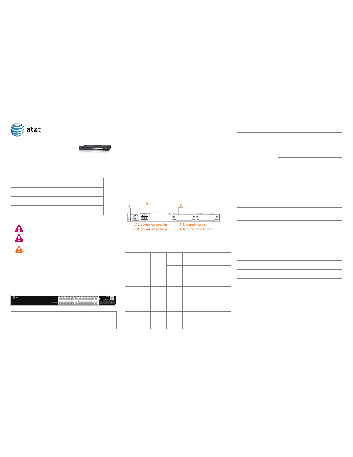
Back panel
The active500EM has one 100-240V 50/60Hz 5A AC power receptacle,
one standby DC power receptacle (48V), one ground connection, and two
expansion slots.
Status LEDs
The active500EM includes 24 port LEDs, power LED, AC power LED, system
automatic diagnoses LED, and 1/2 state LED of the extended module.
LED Panel
symbol
Status Description
Power LED PWR Green Power is operating normally.
Off Power is off or malfunctioning.
Redundancy
power LED
RPU Green Redundancy power unit is
charging.
Off Redundancy power unit is off or
malfunctioning.
System
automatic
diagnoses LED
DIAG Blink
(Green)
System automatic diagnoses
are underway.
Green System automatic diagnoses
completed.
Amber System automatic diagnose is
malfunctioning.
Extended
module LED
Module1/
Module2
Green Extended module is installed.
Amber The installed extended module
is disabled.
Off No extended module.
LED Panel
symbol
Status Description
Link/Activity Amber Ports are in the link state of 10M
or 100M.
Green Ports are in the link state of
1000M.
Blink
(Amber)
Ports are in the active state of
10M or 100M.
Blink
(Green)
Ports are in the active state of
1000M.
Off No link connection or link
connection has failed.
Power system
AC Power - Rated AC power voltage range: 100V-240V
Current: AC: 5A
Frequency: 50/60Hz (±3Hz)
System specifications
Dimension (W x H x D) 440x328.4x43.4 mm
(17.33 x 12.93 x 1.71 in.)
Extended card dimension (Wx H) 107x145.9 mm (4.21x5.75 in.)
Weight 4.85kg (9.67 lb)
Fixed port 20 RJ-45 ports and 4 combo ports (4
SFP and 4 RJ-45)
Management port 1 RJ-45 serial console port
Extended slot 2
Power input AC 100V–240V
DC -48V (-48V– -60V)
Max consumption System 160W
Operating temperature 0°C–50°C
Storage temperature -40°C–70°C
Relative humidity 5%–95%, non-condensing
Mean time between failure Min 120,000 hours MTBF
Maximum operating altitude 7000 ft (2km)
Current AC: 5A; DC: 4A
IMPORTANT: The weight is the machine chassis weight with two extended
modules.
Environmental requirements
• The switch must be installed in a clean area; otherwise, the switch may
be damaged by electrostatic adherence.
• The switch must be maintained within system specifications.
• Ensure sufficient spacing around the switch for good air circulation.
• Avoid placing the switch in direct sunlight. Keep the switch away from
heat sources and strong electromagnetic interference sources.
Page 2
2
• The switch must be mounted to a standard 19’’ rack or placed on a
clean, level desktop.
• The switch must be installed near an accessible power socket outlet.
When using DC input power, please make sure that a 4A circuit breaker
is used and is available near the controller installation site for easy
power off.
• The switch can be installed at a maximum altitude of 7,000 feet (2km).
• The DC power supply is screwed directly into the back of the
active500EM, creating a permanent connection. Therefore, an
appropriate disconnect device should be provided externally to the
active500EM in the case an urgent shutdown is required. The following
types of disconnect devices can be used:
• The main supply plug on the power supply cord.
• An appliance coupler.
• An isolating switch.
• A circuit-breaker.
• Any equivalent device.
Security warnings
• Do not place anything on top of the switch.
• Do not install, move, or relocate the switch and its modules when the
switch is in operation.
• Do not open the switch shell.
• Do not drop metals into the switch. This can cause the switch to shortcircuit.
• Do not touch the power plug or power socket.
• Use standard power sockets, which have overload and leakage
protection.
• Have the emergency power switch on site. In case of emergency, switch
off the power immediately.
Preventing electrostatic discharge damage
CAUTION: Improper power supply system grounding,
extreme fluctuation of the input source, and transients (or
spikes) can result in larger error rate or hardware damage.
Electrostatic discharges (ESD) can cause damage to internal circuits and
the entire switch, and may cause physical injury. To avoid ESD damage:
• Ensure proper grounding of the device.
• Perform regular cleaning to reduce dust.
• Maintain proper temperature and humidity.
• Always wear an ESD wrist strap and antistatic uniform when in contact
with the switch.
Installation notice
• Read the instructions carefully before installation and operation. Prepare
installation materials, tools and installation site.
• Use the brackets and screws provided in the accessory kit with the proper
tools to perform the installation. Always wear an antistatic uniform and
ESD wrist straps. Use standard cables and connectors.
• Clean the site after installation, and ensure the switch is well grounded
before powering on.
CAUTION: Potential risks include: electric leakage, power
supply arcing, power line breakage, overloaded circuit, and
electrical short circuit. If electrical shock, fire, or electrical
short circuit occurs, cut off electricity and seek help.
Device installation
Required tools
• Screwdrivers, both Phillips (crosshead) and Standard (flat-head)
• ESD wrist strap & antistatic uniform
Installing the switch
To mount the active500EM on the 19’’ rack:
1. Attach the two brackets on the active500EM with screws provided in the
accessory kit.
2. Put the bracket-mounted switch into a standard 19’’ rack. Fasten the
active500EM to the rack with the screws provided. Leave enough space
around the switch for good air circulation.
CAUTION: The brackets are used to mount the switch to the
rack, and are not load-bearing. Place a rack shelf under the
switch. Do not place anything on top of the switch. Do not
block the vents on the switch to ensure the proper operation.
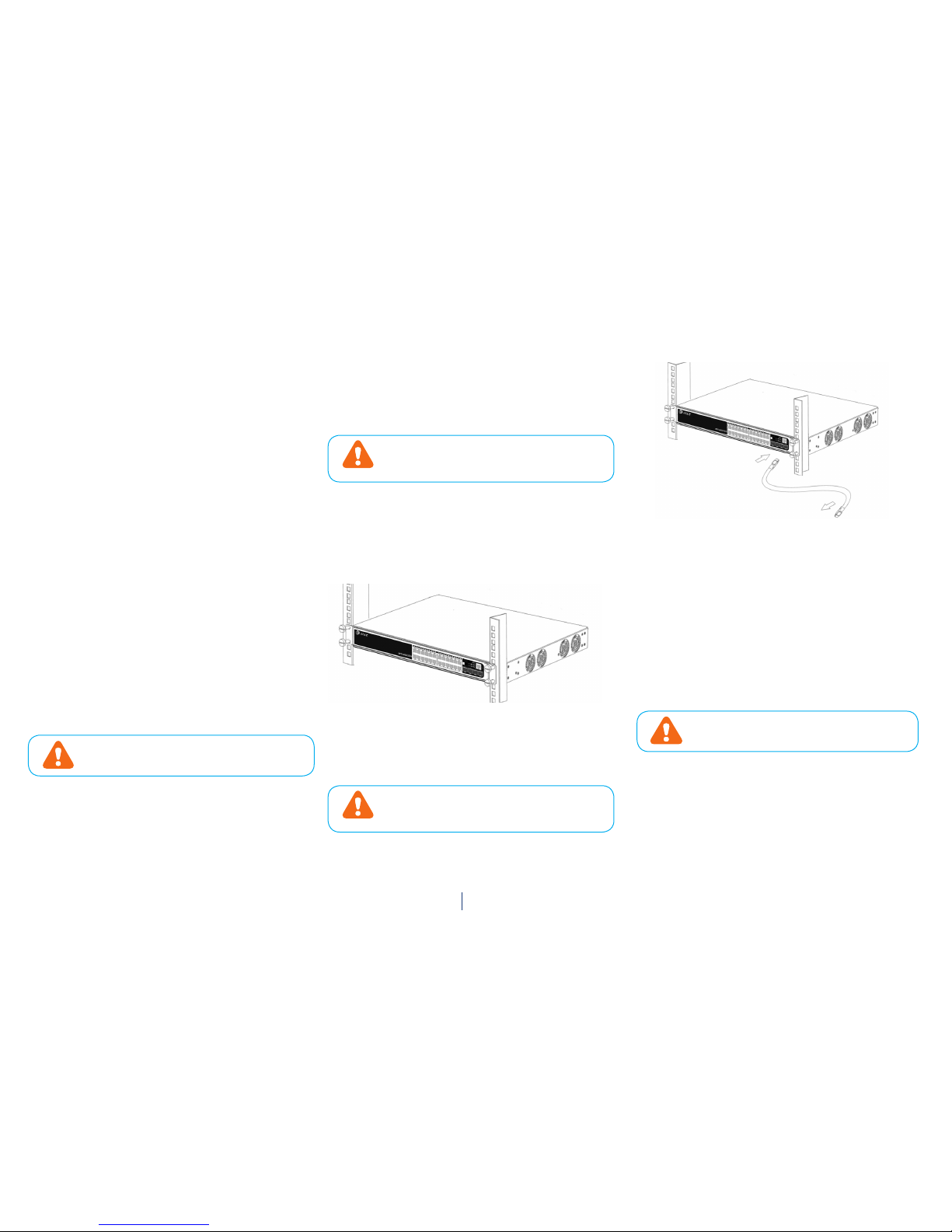
Connecting the console
The active500EM provides a serial console port.
To connect the console to the active500EM Access Control switch:
1. Attach the console cable (included) end to the console port of the
switch.
2. Connect the other side of the console cable to a COM port .
3. Turn on both the switch and the COM port, and configure the switch
through the COM port.
Copper cable cable connection
1. Insert one end of the Ethernet cable into the RJ-45 Ethernet port in the
switch copper port.
2. Insert the other end of the Ethernet cable into the RJ-45 Ethernet port
of the other device.
3. Check all status indicators for the corresponding ports; a lit LED
indicates that the link has been established. Otherwise, the link is not
ready and the cable should be examined.
CAUTION: Verify the label above the port before
connecting cables. Connecting to the wrong port may
damage the switch.
AC power supply connection
1. Insert one end of the power cable (included) into the power source
socket, and the other end into a standard power socket.
2. Check if the power status indicator in the front panel of the switch is
lit. The active500EM is self-adjustable for the input voltage. When the
input voltage is in the range printed on the switch surface, the switch
can operate correctly.
Page 3

3
3. When the switch is powered on, it executes self-test procedures and
starts up.
CAUTION: The input voltage must be within the required
range; otherwise the switch can be damaged or may
malfunction. Do not open the switch shell as physical
injury may occur.
Switch management
Network administrators can use a simple-to-configure web Graphical User
Interface (GUI) to manage and maintain the switch on their network.
Login web network management
The default Web login process and details are identified below. The default
Web login information includes:
Username: admin
Password: admin
IP address of the switch: 192.168.1.1
1. Connect the switch to PC by using an Ethernet cable (not included) to
connect the PC to one of the switch’s Ethernet ports.
2. Configure the IP address for the PC and ensure that it can
communicate with the switch. The connection between the switch and
PC can be done by a direct connection or through the network.
For example, change the IP address to 192.168.1.17 to ensure that the PC
and switch are in the same IP subnet.
3. Launch your PC’s web browser and type http://192.168.1.1 in the
address bar. Press Enter.
4. On the login page, type admin in the Username field, and type admin in
the Password field. Click Login.
5. To quit and exit, click the log off button on the upper right corner on the
web network management page.
© 2014 International Communications Corporation, Inc. All Rights Reserved. AT&T and the AT&T
logo are trademarks of AT&T Intellectual Property licensed to lnternational Communications
Corporation, Riverside, California. Printed in U.S.A. Issue 5.1 AT&T 04/28/14. activeARC is a
registered trademark of International Communications Corporation,Inc.
Contact information
Phone: 1-855.MYARC11 (855.692.7211)
E-mail: support@activearc.att-mail.com
sales@activearc.att-mail.com
www.att.com/activearc
activeARC® web management
The web network management page includes: navigation bar, configuration
area, and help area shown below.
 Loading...