

Atmel ATmega328PB Xplained Mini User Manual
AVR 8-bit Microcontrollers
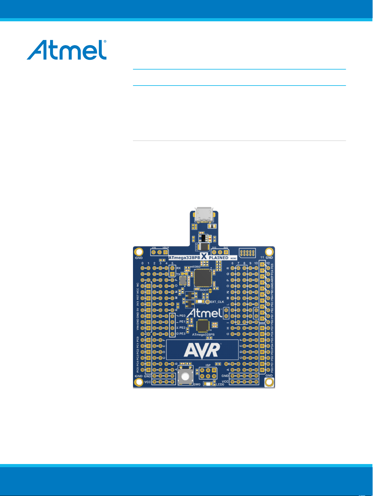
ATmega328PB Xplained Mini
USER GUIDE
Introduction
This user guide describes how to get started with the Atmel® ATmega328PB
Xplained Mini board. The ATmega328PB Xplained Mini evaluation kit is a
hardware platform to evaluate the Atmel ATmega328PB microcontroller. The
evaluation kit comes with a fully integrated debugger that provides seamless
integration with Atmel Studio 6.2 (and later version). The kit provides access
to the features of the ATmega328PB enabling easy integration of the device
in a custom design.
Atmel-42469A-ATmega328PB-Xplained-Mini_User Guide-07/2015

Table of Contents
Introduction......................................................................................................................1
1. Getting Started...........................................................................................................3
1.1. Features....................................................................................................................................... 3
1.2. Design Documentation and Related Links................................................................................... 3
1.3. Xplained Mini Quick Start............................................................................................................. 3
1.3.1. Connect to Atmel Studio................................................................................................ 3
1.3.2. Connect to the COM Port.............................................................................................. 4
1.4. Programming and Debugging...................................................................................................... 4
1.4.1. Programming the Target using mEDBG........................................................................ 4
1.4.2. Debugging the Target using mEDBG.............................................................................5
1.4.3. Programming the Target using an External Programmer.............................................. 6
1.4.4. Programming the ATmega32U4 using an External Programmer...................................6
1.4.5. Programming the ATmega32U4 using a Bootloader..................................................... 7
1.5. Board Assembly........................................................................................................................... 8
1.5.1. Custom Assembly..........................................................................................................8
1.5.2. Standalone Node........................................................................................................... 8
1.5.3. Connecting an Arduino Shield....................................................................................... 8
1.6. mEDBG Command Line Interface................................................................................................8
1.6.1. mEDBG Low Power Modes........................................................................................... 8
1.6.2. mEDBG Fuse Filter........................................................................................................8
1.6.3. How to Issue Commands...............................................................................................8
2. Hardware User Guide.............................................................................................. 11
2.1. Board Overview.......................................................................................................................... 11
2.2. Target Headers and Connectors.................................................................................................11
2.2.1. Target Digital I/O.......................................................................................................... 11
2.2.2. Board Power Header................................................................................................... 12
2.2.3. Target Analogue I/O.....................................................................................................12
2.2.4. Target Programming.................................................................................................... 13
2.2.5. Target Additional I/O.................................................................................................... 13
2.3. Target GUI.................................................................................................................................. 13
2.3.1. Push Button................................................................................................................. 14
2.3.2. User LED..................................................................................................................... 14
2.3.3. QTouch buttons............................................................................................................15
2.4. On-board Power Supply............................................................................................................. 16
2.5. mEDBG...................................................................................................................................... 16
2.5.1. mEDBG Status LED.................................................................................................... 16
2.5.2. mEDBG External Clock............................................................................................... 17
2.5.3. mEDBG COM Port Connection................................................................................... 17
2.5.4. mEDBG JTAG Interface...............................................................................................17
2.5.5. mEDBG USB Interface................................................................................................ 18
2.6. Extension Header Area.............................................................................................................. 18
2.7. Factory Programmed..................................................................................................................19
2.8. Document Revision History........................................................................................................ 20
Atmel ATmega328PB Xplained Mini [USER GUIDE]
Atmel-42469A-ATmega328PB-Xplained-Mini_User Guide-07/2015
2

1. Getting Started
1.1. Features
The ATmega328PB Xplained Mini evaluation board provides a development platform for the Atmel
ATmega328PB.
Key Features
• On-board debugger with full source-level debugging support in Atmel Studio
• Auto-ID for board identification in Atmel Studio
• Access to all signals on target MCU
• One green mEDBG status LED
• One yellow user LED
• One mechanical user push button
• QTouch® user area
• Virtual COM port (CDC)
• External target CLK 16MHz at 5V, 8MHz at 3.3V
• USB powered
• 3V3 regulator
• Arduino shield compatible foot prints
• Target SPI bus header foot print
• Xplained Pro extension headers can easily be strapped in
1.2. Design Documentation and Related Links
The most relevant documents and software for the evaluation board are available here:
Design Documentation - ZIP file containing CAD source, schematics, BOM, assembly drawings, 3D plots,
layer plots, etc.
Atmel Studio - Free Atmel IDE for development of C/C++ and assembler code for Atmel microcontrollers.
Xplained - Atmel Xplained prototyping and evaluation platform.
Atmel Spaces - Open Source projects for Xplained Mini.
1.3. Xplained Mini Quick Start
How to connect the ATmega328PB Xplained Mini board embedded debugger to Atmel Studio and how to
connect the ATmega328PB UART to a COM port.
1.3.1. Connect to Atmel Studio
How to connect the ATmega328PB Xplained Mini board embedded debugger to Atmel Studio to get
started with SW development.
1. Download and install Atmel Studio version 6.2 or later versions.
2. Launch Atmel Studio.
3. Connect the board to the USB port and it will be visible in Atmel Studio.
Atmel ATmega328PB Xplained Mini [USER GUIDE]
Atmel-42469A-ATmega328PB-Xplained-Mini_User Guide-07/2015
3
1.3.2. Connect to the COM Port
How to connect the ATmega328PB UART to a COM port.
All Xplained Mini boards have an embedded debugger (mEBDG) with a number of features, among them
a CDC/COM port, which enables the user to connect the ATmega328PB UART to the PC.
1. Connect the Xplained Mini USB to the PC.
2. A COM port named "mEDBG Virtual COM Port" will be available.
3. Start a terminal emulator or other applications using the COM port, typical COM port settings are
9600 baud N81.
1.4. Programming and Debugging
Programming and debugging the ATmega328PB Xplained Mini.
The target micro-controller is the ATmega328PB.
The mEDBG FW is running on the ATmega32U4.
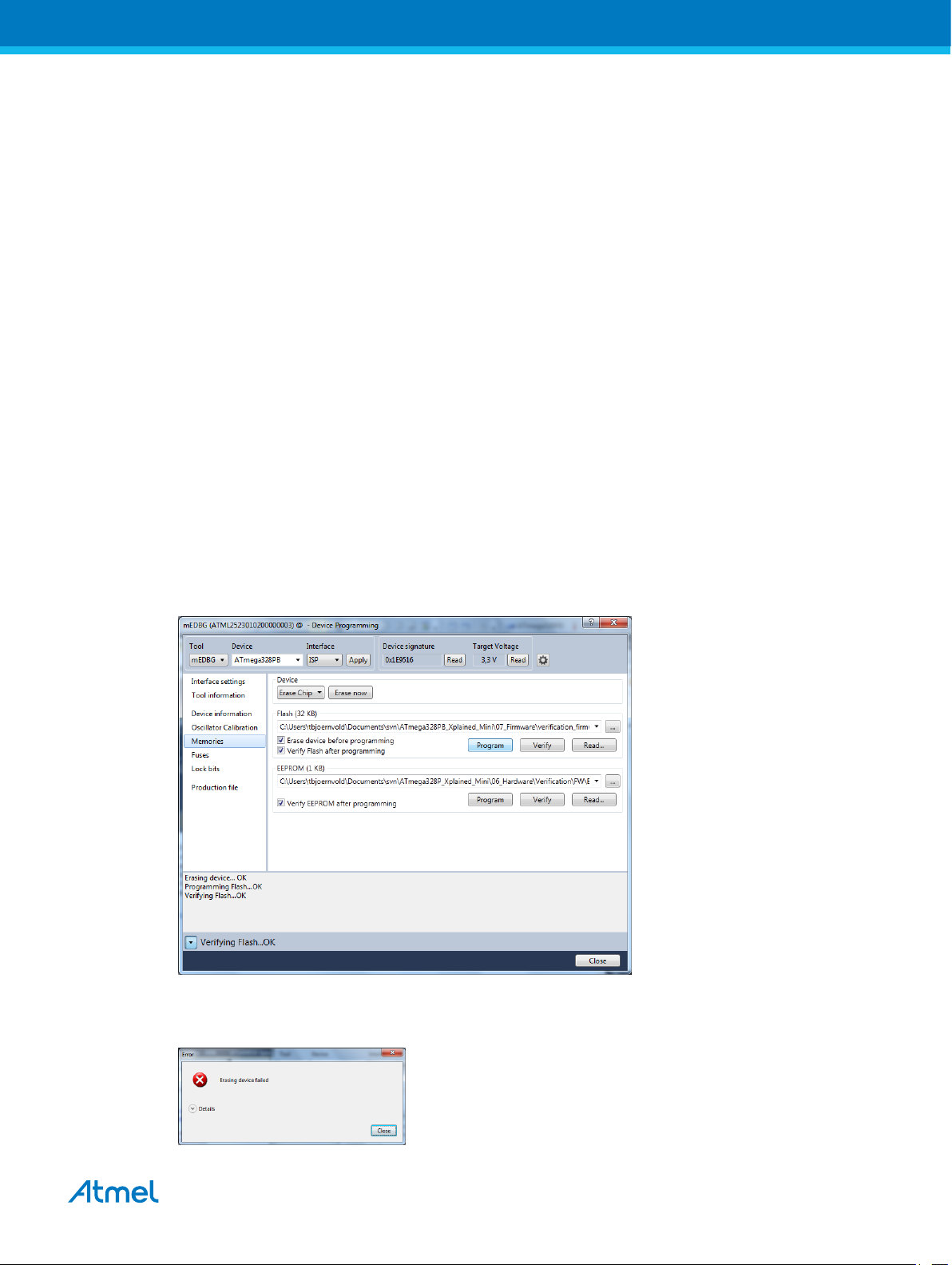
1.4.1. Programming the Target using mEDBG
Using the Embedded Debugger on the ATmega328PB Xplained Mini board to program the
ATmega328PB and setting the fuses.
1. Connect the Xplained Mini USB to the PC.
2. Go to Atmel Studio: click the Tools tab, select Device Programming, and select the connected
mEDBG as Tool with Device as ATmega328PB and Interface to SPI, click Apply.
3. Select "Memories" and locate the source .hex or .elf file and click Program.
4. NOTE: If a previous debug session was not closed by selecting "Disable debugWIRE and Close" in
the Debug menu, the DWEN fuse will be enabled and the target will still be in debug mode, i.e. it
will not be possible to program the target using the SPI.
Atmel ATmega328PB Xplained Mini [USER GUIDE]
Atmel-42469A-ATmega328PB-Xplained-Mini_User Guide-07/2015
4
5. If the source file contains fuse settings, select "Production file" and upload the .elf file to program
the fuses.
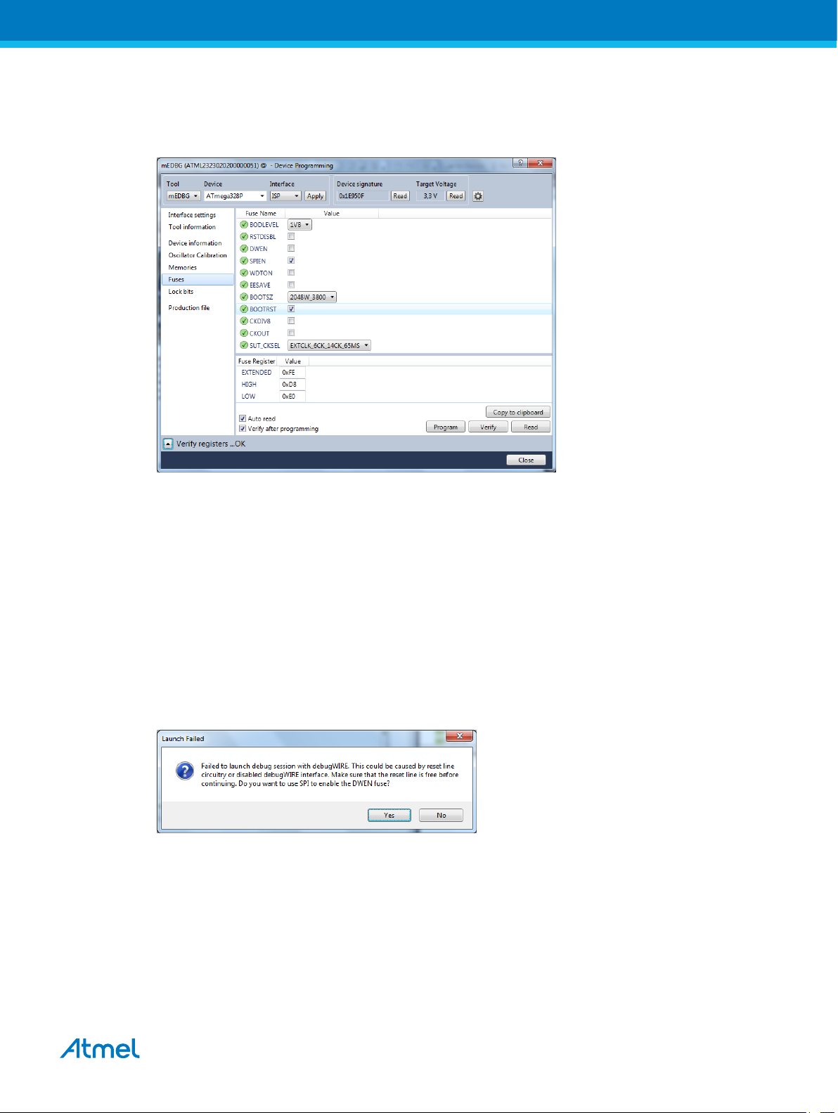
6. Select "Fuses" to program the fuses manually. Set the fuse(s) and click "Program". Recommended
fuse settings:
1.4.2. Debugging the Target using mEDBG
Using the Embedded Debugger on the ATmega328PB Xplained Mini board to debug the ATmega328PB
via debugWIRE.
1. Start Atmel Studio.
2. Connect the Xplained Mini USB to the PC.
3. Open your project.
4. Click the "Project" tab and select the project "properties", click the "Tools" tab and select mEDBG
as debugger and debugWIRE as interface.
5. Click the "Debug" tab and select "Start Debugging and Break".
6. Atmel Studio will display an error message if the DWEN fuse in the ATmega328PB is not enabled,
click YES to make Studio set the fuse using the SPI interface.
7. A debug session is started with a break in main, debugging can start.
8. When exiting debug mode select "Disable debugWIRE and Close" in the Debug tab, this will
disable the DWEN fuse.
Atmel ATmega328PB Xplained Mini [USER GUIDE]
Atmel-42469A-ATmega328PB-Xplained-Mini_User Guide-07/2015
5
Important: If not exiting debug mode by selecting "Disable debugWIRE and Close" in the
Debug menu, the DWEN fuse will be enabled and the target will still be in debug mode, i.e. it
will not be possible to program the target using the SPI.
Important: If any other CPU CLK than the external CLK supplied by the mEDBG is used the
debugWIRE is not guaranteed to work.
Important: Applying a signal to J202/RESET (the RESET_SENSE signal) while debugging
may result in unexpected behaviour. This signal is NOT available during a debugging session
because the RESET line is actively used by the debugWIRE interface
1.4.3. Programming the Target using an External Programmer
How to program the target ATmega328PB using the AVR® JTAGICE mkII, JTAGICE3, Atmel-ICE, or
other Atmel Programmers.
1. Connect the External Programmer USB to the PC.
2. Connect the External Programmer to the ATmega328PB Xplained Mini board SPI connector.
3. Go to Atmel Studio: click the Tools tab, select Device Programming, and select the External
Programmer connected as Tool with Device as ATmega328PB and Interface to SPI, click Apply.
4. Select "Memories" and locate the source .hex or .elf file and click Program.
1.4.4. Programming the ATmega32U4 using an External Programmer
How to program the ATmega32U4 using the AVR® JTAGICE mkII, JTAGICE3, Atmel-ICE, or other Atmel
Programmers.
1. Connect the External Programmer USB to the PC.
2. Connect the External Programmer to the ATmega328PB Xplained Mini board JTAG connector.
3. Go to Atmel Studio: click the Tools tab, select Device Programming, and select the connected
mEDBG as Tool with Device as ATmega32U4 and Interface to JTAG, click Apply.
4. Select "Memories" and locate the source .hex or .elf file and click Program.
Atmel ATmega328PB Xplained Mini [USER GUIDE]
Atmel-42469A-ATmega328PB-Xplained-Mini_User Guide-07/2015
6
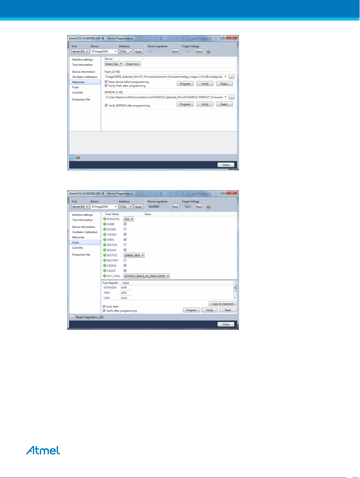
5. Select "Fuses" to program the fuses manually. Set the fuse(s) and click "Program". Recommended
fuse settings:
1.4.5. Programming the ATmega32U4 using a Bootloader
This section describes how to use the bootloader to program the ATmega32U4.
1. Install the Bootloader interface on the PC, download the installer from FLIP.
2. Start the Bootloader PC GUI "FLIP".
3. Short strap J102.
4. Connect the ATmega328PB Xplained Mini board USB connector to the PC.
5. Select Device = ATmega32U4 (Device - Select).
6. Select USB communication (Ctrl+U).
7. Select memory area to program (use the toggle memory button bellow the Atmel logo).
8. Select Load Hex file (Ctrl+L).
Atmel ATmega328PB Xplained Mini [USER GUIDE]
Atmel-42469A-ATmega328PB-Xplained-Mini_User Guide-07/2015
7
 Loading...