


ZT
Atlas Copco ZT, ZT15, ZR, ZT22, ZT18 Instruction Book
...
Instruction book
Atlas Copco Stationary Air Compressors
ZT15, ZT18, ZT22, ZT30, ZT37, ZT45
ZR30, ZR37, ZR45
Instruction book
Copyright 2004, Atlas Copco Airpower n.v., Antwerp, Belgium.
Any unauthorized use or copying of the contents or any part thereof is prohibited. This applies in
particular to trademarks, model denominations, part numbers and drawings.
This instruction book meets the requirements for instructions specified by the machinery directive
98/37/EC and is valid for CE as well as non-CE labelled machines
No. 2920 1472 03
Replaces 2920 1472 02
Registration code: APC Z<55 + VSD / 38 / 392
2004-05 www.atlascopco.com
2920 1472 03 1

Instruction book
This instruction book describes how to handle and operate the subject machine(s) to ensure safe
operation, optimum working economy and long service life.
Read this book before putting the machine into operation to ensure correct handling, operation and
proper maintenance from the beginning. The maintenance schedule comprises measures for keeping
the compressor in good repair.
Keep the book available for the operator(s) and make sure that the compressor is operated and that
maintenance is carried out according to the instructions. Record all operating data, maintenance work
effected, etc. in an operator's logbook available from Atlas Copco. Follow all applicable safety
precautions, amongst others those mentioned in this book.
Repairs must be carried out by trained personnel from Atlas Copco who can also be contacted for any
further information.
In all correspondence mention the type and the serial number, shown on the data plate.
For all data not mentioned in the text, see sections "Preventive maintenance schedule" and "Principal
data".
The company reserves the right to make changes without prior notice.
2920 1472 03 2

Instruction book
1 LEADING PARTICULARS................................................................................................................... 5
1.1 General description........................................................................................................................ 5
1.2 Air flow (Figs. 1.6/1.7) .................................................................................................................. 10
1.3 Condensate drain system (Figs. 1.6/1.7).....................................................................................10
1.4 Oil system (Figs. 1.6/1.7)............................................................................................................. 10
1.5 Cooling system (Figs. 1.6/1.7) ..................................................................................................... 10
1.6 Air dryer on Full-Feature.............................................................................................................. 17
1.6.1 Compressors with an ID dryer (Figs. 1.6) ............................................................................. 17
1.6.2 Compressors with an IMD dryer (Figs. 1.7) .......................................................................... 17
1.7 Electrical system .......................................................................................................................... 18
1.8 Elektronikon control system......................................................................................................... 19
1.8.1 Automatic control of the compressor..................................................................................... 19
1.8.2 Protecting the compressor .................................................................................................... 19
1.8.3 Service warning..................................................................................................................... 19
1.8.4 Automatic restart after voltage failure ...................................................................................19
1.9 Control panel................................................................................................................................ 20
1.9.1 LEDs/buttons/keys ................................................................................................................ 20
1.9.2 Display................................................................................................................................... 21
1.9.3 Function keys (5-Fig. 1.10) ................................................................................................... 21
1.9.4 Emergency stop button (S3-Fig. 1.10) .................................................................................. 22
1.10 Menu-driven control programs................................................................................................... 22
1.10.1 Function of control programs .............................................................................................. 22
1.10.2 Main screen......................................................................................................................... 23
1.10.3 External compressor status indication ................................................................................ 23
2 INSTALLATION ................................................................................................................................. 25
2.1 Dimension drawings..................................................................................................................... 25
2.2 Installation proposal (Figs. 2.6/2.7).............................................................................................. 30
2.3 Electric cables.............................................................................................................................. 34
2.3.1 ZT15 up to ZT22 IEC............................................................................................................. 34
2.3.2 ZT15 up to ZT22 CSA/UL ..................................................................................................... 34
2.3.3 ZT/ZR30 up to ZT/ZR45 IEC.................................................................................................35
2.3.4 ZT/ZR30 up to ZT/ZR45 CSA/UL.......................................................................................... 35
2.4 Pictographs (Figs. 2.9 and 2.10).................................................................................................. 38
2.5 Cooling water requirements......................................................................................................... 39
2.5.1 Type of the system ................................................................................................................ 39
2.5.2 Cooling water parameters ..................................................................................................... 39
3 OPERATING INSTRUCTIONS .......................................................................................................... 43
3.1 Initial start-up ............................................................................................................................... 43
3.2 Starting (Fig. 3.4) ......................................................................................................................... 48
3.3 During operation (Fig. 3.4)........................................................................................................... 48
3.3.1 Checking the display (2-Fig. 3.4) .......................................................................................... 48
3.3.2 On compressors with an IMD dryer (Fig. 1.5) ....................................................................... 50
3.4 Stopping (Fig. 3.4) ....................................................................................................................... 50
3.5 Taking out of operation ................................................................................................................ 50
4 MAINTENANCE ................................................................................................................................. 51
4.1 Preventive maintenance schedule for the compressor................................................................ 51
4.1.1 Regular service operations ................................................................................................... 51
4.1.2 Service kits ............................................................................................................................ 51
4.1.3 Service agreements .............................................................................................................. 51
4.1.4 Service plan........................................................................................................................... 52
4.2 Motor greasing ............................................................................................................................. 52
4.2.1 Fan motor (ZT) ...................................................................................................................... 52
4.2.2 Drive motor (M1-Fig. 1.2) ...................................................................................................... 52
4.3 Oil specifications .......................................................................................................................... 52
4.4 Storage after installation .............................................................................................................. 52
4.5 Service kits................................................................................................................................... 52
5 SERVICING PROCEDURES ............................................................................................................. 54
2920 1472 03 3

Instruction book
5.1 Air filter (AF-Fig. 1.3).................................................................................................................... 54
5.2 Oil and oil filter change (Fig. 3.3)................................................................................................. 54
5.3 Safety valves................................................................................................................................ 54
6 PROBLEM SOLVING ........................................................................................................................ 55
7 PRINCIPAL DATA ............................................................................................................................. 56
7.1 Readings on display (2-Fig. 3.4).................................................................................................. 56
7.2 Settings of safety valves .............................................................................................................. 56
7.3 Settings of overload relay - circuit breakers – fuses.................................................................... 57
7.4 Compressor specifications........................................................................................................... 59
7.5 Conversion list of SI units into British/American units ................................................................. 61
5.1.1 Recommendations ................................................................................................................ 54
5.1.2 Servicing................................................................................................................................ 54
7.1.1 ZT15 up to ZT22.................................................................................................................... 56
7.1.2 ZT30 up to ZT45.................................................................................................................... 56
7.1.3 ZR30 up to ZR45................................................................................................................... 56
7.3.1 ZT15 up to ZT22 IEC............................................................................................................. 57
7.3.2 ZT15 up to ZT22 CSA/UL ..................................................................................................... 57
7.3.3 ZT/ZR30 up to ZT/ZR45 IEC.................................................................................................58
7.3.4 ZT/ZR30 up to ZT/ZR45 CSA/UL.......................................................................................... 58
7.4.1 Reference conditions ............................................................................................................ 59
7.4.2 Limitations ............................................................................................................................. 59
7.4.3 Specific data of ZT15 up to ZT22..........................................................................................59
7.4.4 Specific data of ZT30 up to ZT45..........................................................................................60
7.4.5 Specific data of ZR30 up to ZR45 ......................................................................................... 60
8 INSTRUCTIONS FOR USE OF PULSATION DAMPER................................................................... 62
9 PED .................................................................................................................................................... 62
9.1 Components subject to 97/23/EC Pressure Equipment Directive ............................................... 62
9.2 Overall rating................................................................................................................................ 62
2920 1472 03 4
Instruction book
1 LEADING PARTICULARS
1.1 General description
ZT15 up to ZT45 and ZR30 up to ZR45 are two-stage tooth compressors, driven by an electric motor.
The compressors deliver oil-free air. ZT are air-cooled and ZR are water-cooled.
The compressors are enclosed in a sound-insulated bodywork and include mainly (Figs. 1.2 up to 1.4):
- Air filter (AF)
- Load/no-load valve (TV)
- Low-pressure compressor element (El)
- Intercooler (Ci)
- High-pressure compressor element (Eh)
- Aftercooler (Ca)
- Electric motor (M1)
- Drive coupling
- Gear casing
- Elektronikon
- Safety valves (SVh/SVl)
Full-Feature compressors are additionally provided with an air dryer (Figs. 1.3/1.5), which removes
moisture from compressed air. See section 1.6.
WorkPlace Air System compressors operate at a very low noise level.
®
regulator (1-Fig. 1.2)
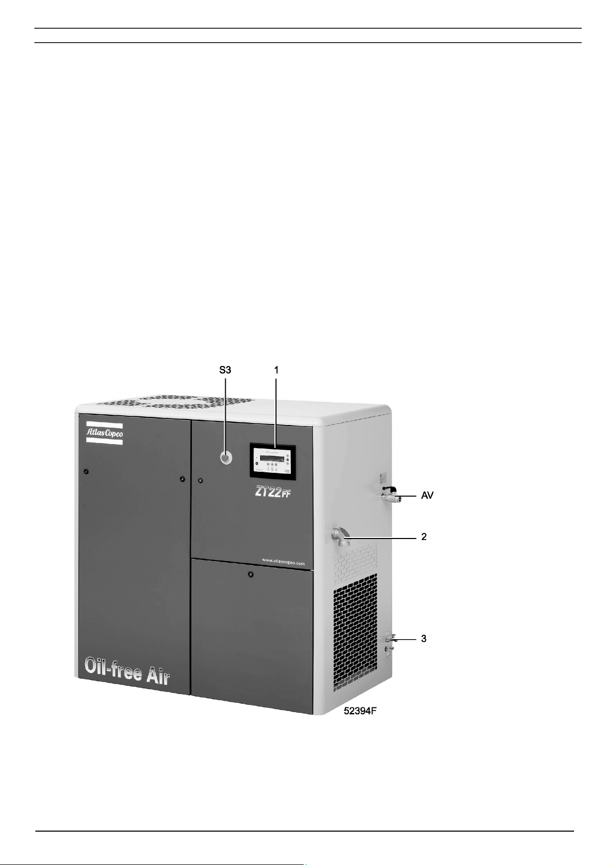
Fig. 1.1 General view
AV Air outlet valve
S3 Emergency stop
button
1 Elektronikon
regulator
2 Electric cable
entry
3 Condensate
drains
2920 1472 03 5
Instruction book
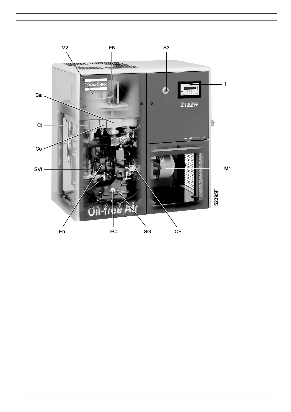
Ca Aftercooler
Ci Intercooler
Co Oil cooler
Eh High-pressure compressor element
FC Oil filler plug
FN Fan
M1 Drive motor
M2 Fan motor
OF Oil filter
SG Oil level sight-glass
SVl Low-pressure safety valve
S3 Emergency stop button
1 Elektronikon regulator
Fig. 1.2 Front view
2920 1472 03 6
Instruction book
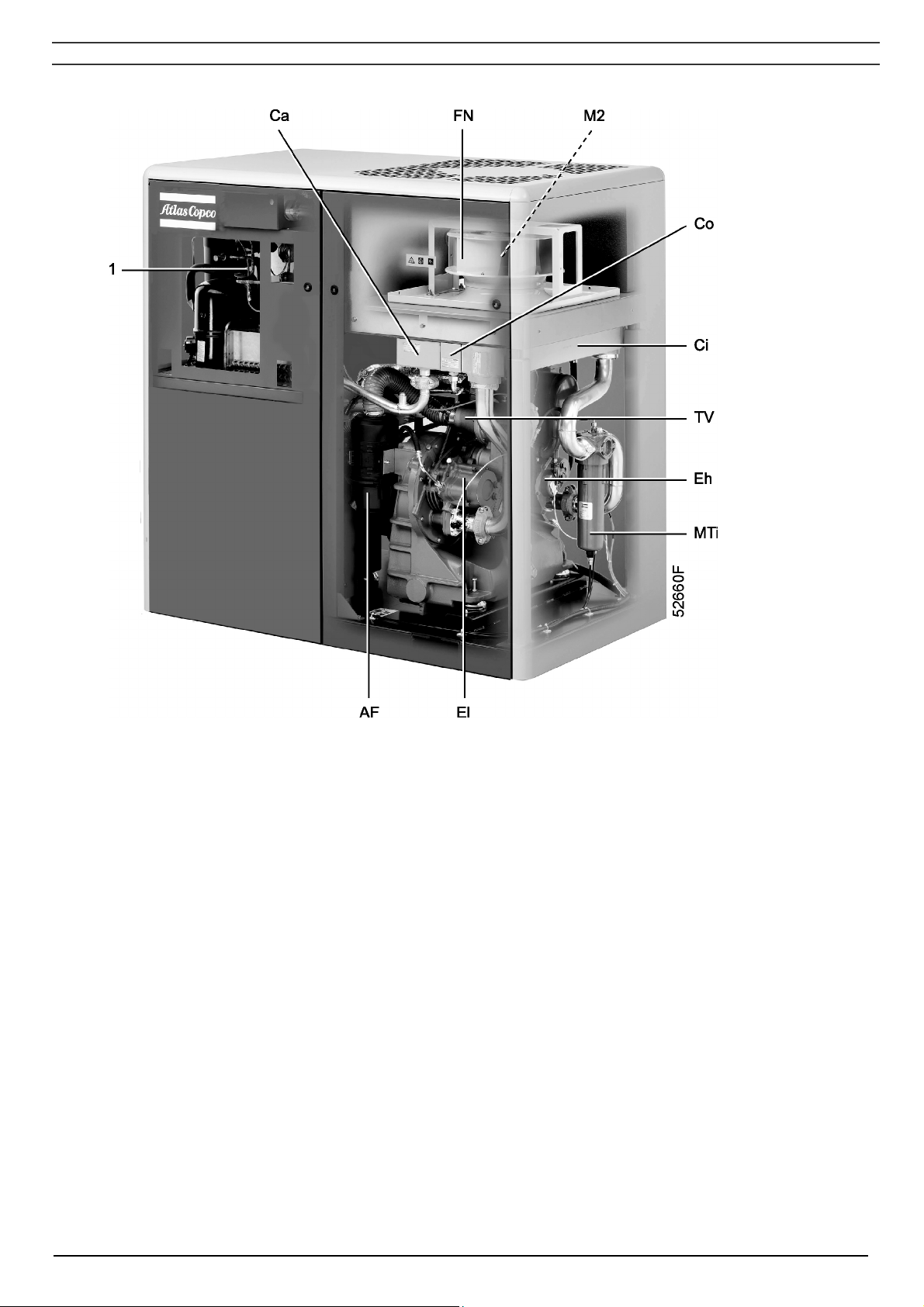
AF Air filter
Ca Aftercooler
Ci Intercooler
Co Oil cooler
Eh High-pressure compressor element
El Low-pressure compressor element
FN Cooling fan
MTi Condensate trap, intercooler
M2 Fan motor
TV Load/no-load valve
1 ID dryer
Fig. 1.3 Rear view, Full-Feature (ID dryer)
2920 1472 03 7
Instruction book
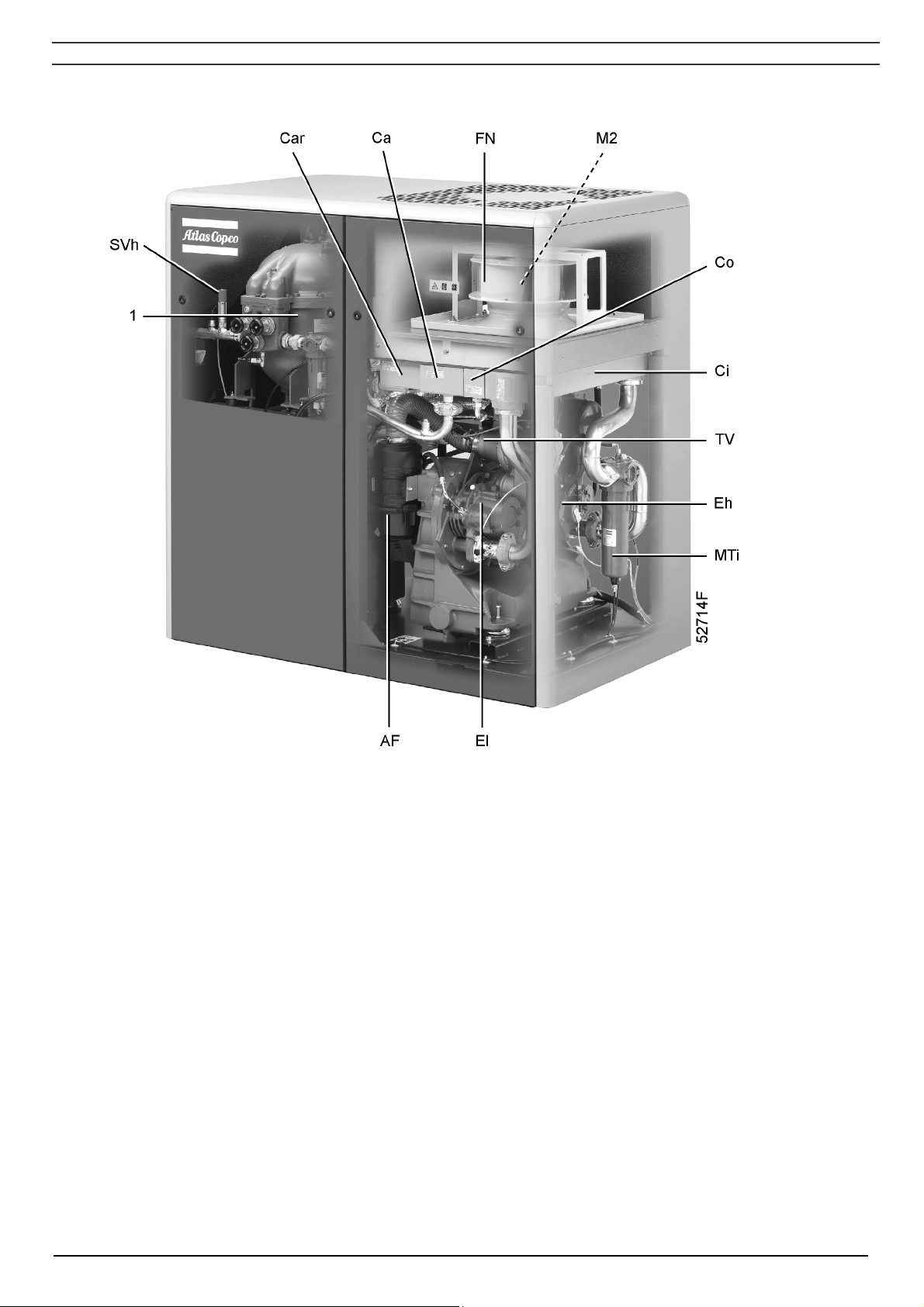
AF Air filter
Ca Aftercooler
Car Cooler, regeneration air
Ci Intercooler
Co Oil cooler
Eh High-pressure compressor element
El Low-pressure compressor element
FN Cooling fan
MTi Condensate trap, intercooler
M2 Fan motor
SVh High-pressure safety valve
TV Load/no-load valve
1 IMD dryer
Fig. 1.4 Rear view, Full-Feature (IMD dryer)
2920 1472 03 8
Instruction book
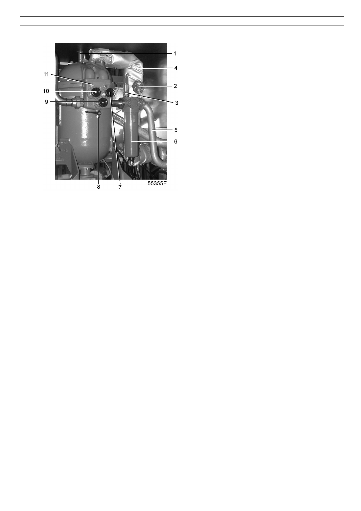
1 Safety valve
2 Shut-off valve, regeneration air
3 Safety valve
4 Inlet regeneration air
5 Inlet pipe, wet compressed air
6 Condensate trap, aftercooler
7 Dryer inlet valve
8 Manual drain valve
9 Dryer by-pass valve
10 Dryer outlet valve
11 Moisture indicator
Fig. 1.5 IMD dryer
2920 1472 03 9

Instruction book
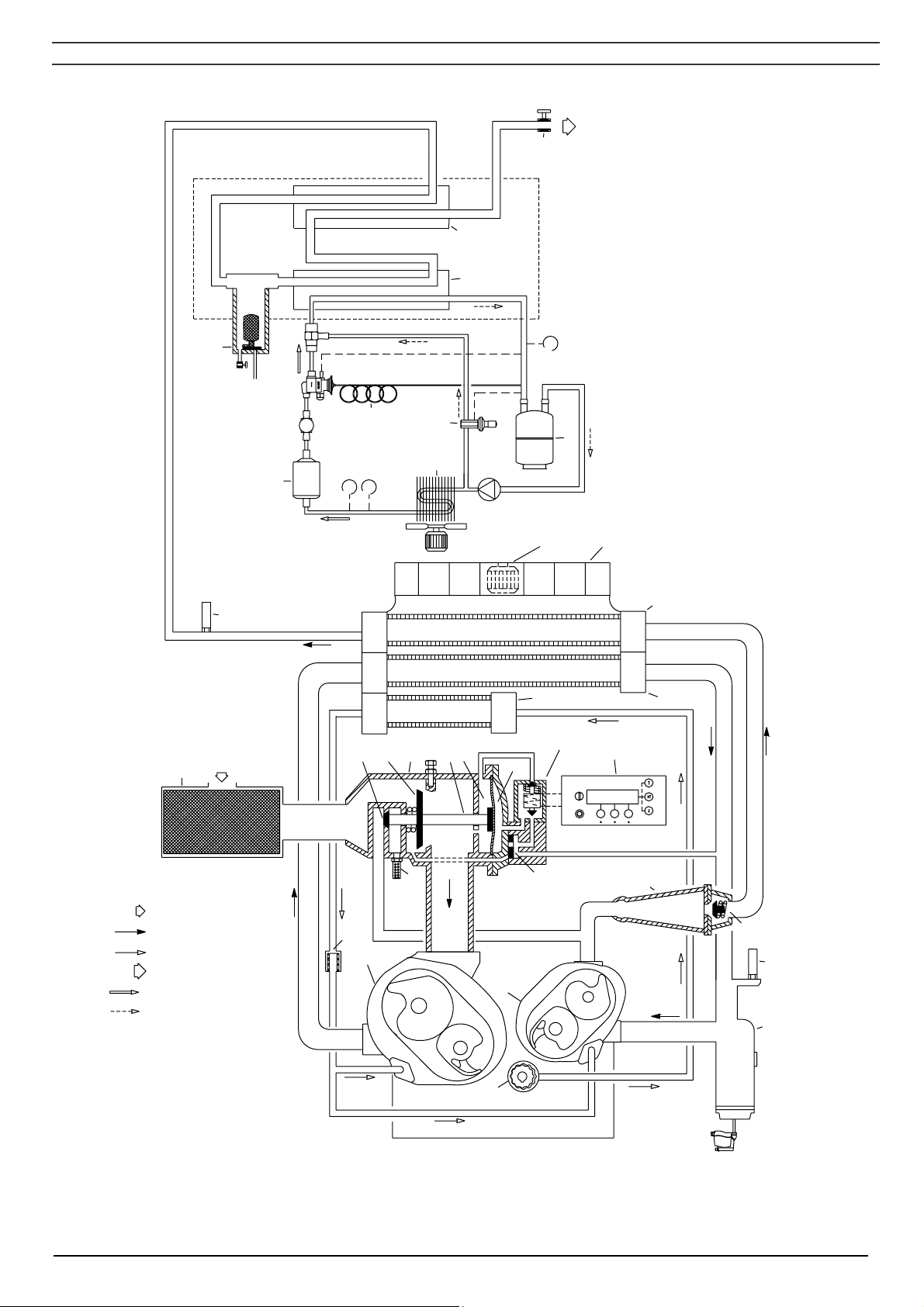
1.2 Air flow (Figs. 1.6/1.7)
Air drawn through filter (AF) is compressed in low-pressure compressor element (El) and discharged
to intercooler (11). The cooled air is further compressed in high-pressure compressor element (Eh)
and discharged through pulsation damper (AS) and aftercooler (15). A check valve (CV) is provided
downstream of the pulsation damper.
1.3 Condensate drain system (Figs. 1.6/1.7)
Two condensate traps are installed: one downstream of the intercooler (MTi) to prevent condensate
from entering the high-pressure compressor element (Eh) and one downstream of the aftercooler
(MTa) to prevent condensate from entering the air outlet pipe. The condensate traps are provided with
a float valve to automatically drain condensate and with a manual drain valve.
For Full-Feature compressors with an ID dryer (Figs. 1.6), the condensate trap downstream the
aftercooler is replaced by a condensate trap (5) in the dryer.
Full-Feature compressors with an IMD dryer (Figs. 1.7) have three additional electronic water drains:
- One on the IMD
- One upstream and downstream the regeneration air cooler
1.4 Oil system (Figs. 1.6/1.7)
Oil is circulated by pump (OP) from the sump of the gear casing through cooler (16) and oil filter (OF)
towards the bearings and timing gears.
The oil system is protected by a valve that opens if the oil pressure should rise above a given value.
The valve is located in the oil filter housing.
1.5 Cooling system (Figs. 1.6/1.7)
ZT compressors
The compressors are provided with an air-cooled oil cooler (16), intercooler (11) and aftercooler (15).
An electric motor-driven fan (FN) generates the cooling air.
ZR compressors
The oil cooler, intercooler and aftercooler are water-cooled.
The water system includes three parallel circuits:
- One for the oil cooler and intercooler.
- One for the aftercooler.
- One circuit is only for compressors with an IMD dryer and contains the regeneration cooler.
Each of these circuits has a separate regulating valve (see section 3.1)
2920 1472 03 10
Instruction book
AV
6
7
5
AF
SVh
8
12
13
10
9
M3
FN2
M2
FN1
15
UV
TV
UA
16
Y1
2
3
1
CM
Elektronikon
F1 F2
11
F3
US
4
AS
AIR INLET (1)
AIR FLOW (2)
OIL FLOW (3)
AIR OUTLET (5)
REFRIGERANT FLUID (6)
OF
El
Eh
CV
SVl
REFRIGERANT GAS (7)
MTi
OP
55347D
EWDi
Fig. 1.6a ZT compressors with an ID dryer
2920 1472 03 11
Instruction book
AF
CM
Elektronikon
F1 F2 F3
AIR INLET (1)
AIR FLOW (2)
OIL FLOW (3)
WATER FLOW (4)
AIR OUTLET (5)
REFRIGIRANT FLUID
REFRIGERANT GAS
(7)
(6)
Y1
2
1
4
El
11
3
SVl
US
UA
Eh
TV
UV
MTi
EWDi
OF
171819
16
OP
AS
CV
15
AV
12
13
M3
10
SVh
8
FN1
Fig. 1.6b ZR compressors with an ID dryer
14
6
7
5
9
55346D
2920 1472 03 12

Instruction book
AF Air filter
AS Pulsation damper
AV Air outlet valve (customer’s installation)
CM Control module
CV Check valve
Eh High-pressure compressor element
El Low-pressure compressor element
EWDi Electronic drain, low-pressure element
FN1 Fan, compressor coolers
FN2 Fan, condenser
M2 Fan motor, compressor coolers
M3 Refrigerant compressor
MTi Condensate trap, intercooler
OF Oil filter
OP Oil pump
SVh Safety valve, high-pressure element
SVi Safety valve, low-pressure element
TV Load/no-load valve
UA Unloader
US Silencer
Y1 Loading solenoid valve
1 Chamber
2 Plunger
3 Chamber
4 Diaphragm
5 Condensate trap, dryer
6 Air/air heat exchanger
7 Air/refrigerant heat exchanger/evaporator
8 Capillary tube
9 Accumulator
10 Refrigerant condenser
11 Intercooler
12 Hot-gas by-pass valve
13 Liquid refrigerant filter/dryer
14 Water outlet valve (customer’s installation)
15 Aftercooler
16 Oil cooler
17 Regulating valve, oil cooler and intercooler water circuit
18 Regulating valve, aftercooler water circuit
19 Water inlet valve (customer’s installation)
Note: References 14 up to 19 apply to ZR compressors only
Figs. 1.6 Flow diagrams/regulating systems for Full-Feature compressors with ID dryer
2920 1472 03 13
Instruction book
AV
SVh
7
28
21
20
19
18
17
5
6
9
8
10
12
29
26
14
27
29
13
FN1
AF
AIR INLET (1)
AIR FLOW (2)
OIL FLOW (3)
AIR OUTLET (5)
MTa
15
16
OF
UV
TV
UA
2
3
US
El
Eh
Y1
1
4
CM
Elektronikon
F1F2F3
11
22
AS
CV
SVl
MTi
OP
55365D
EWDi
Fig. 1.7a ZT compressor with IMD dryer
2920 1472 03 14

Instruction book
AF
CM
Elektronikon
F3
F1 F2
AIR INLET (1)
AIR FLOW (2)
OIL FLOW (3)
WATER FLOW (4)
AIR OUTLET (5)
Y1
2
1
4
El
11
3
SVl
US
UA
Eh
TV
MTi
EWDi
UV
OF
23
16
AS
15
24
31
OP
CV
30
7
SVh
28
21
20
19
18
17
5
6
9
AV
Fig. 1.7b ZR compressor with IMD dryer
8
10
29
12
29
22
25
MTa
26
14
27
55364D
2920 1472 03 15

Instruction book
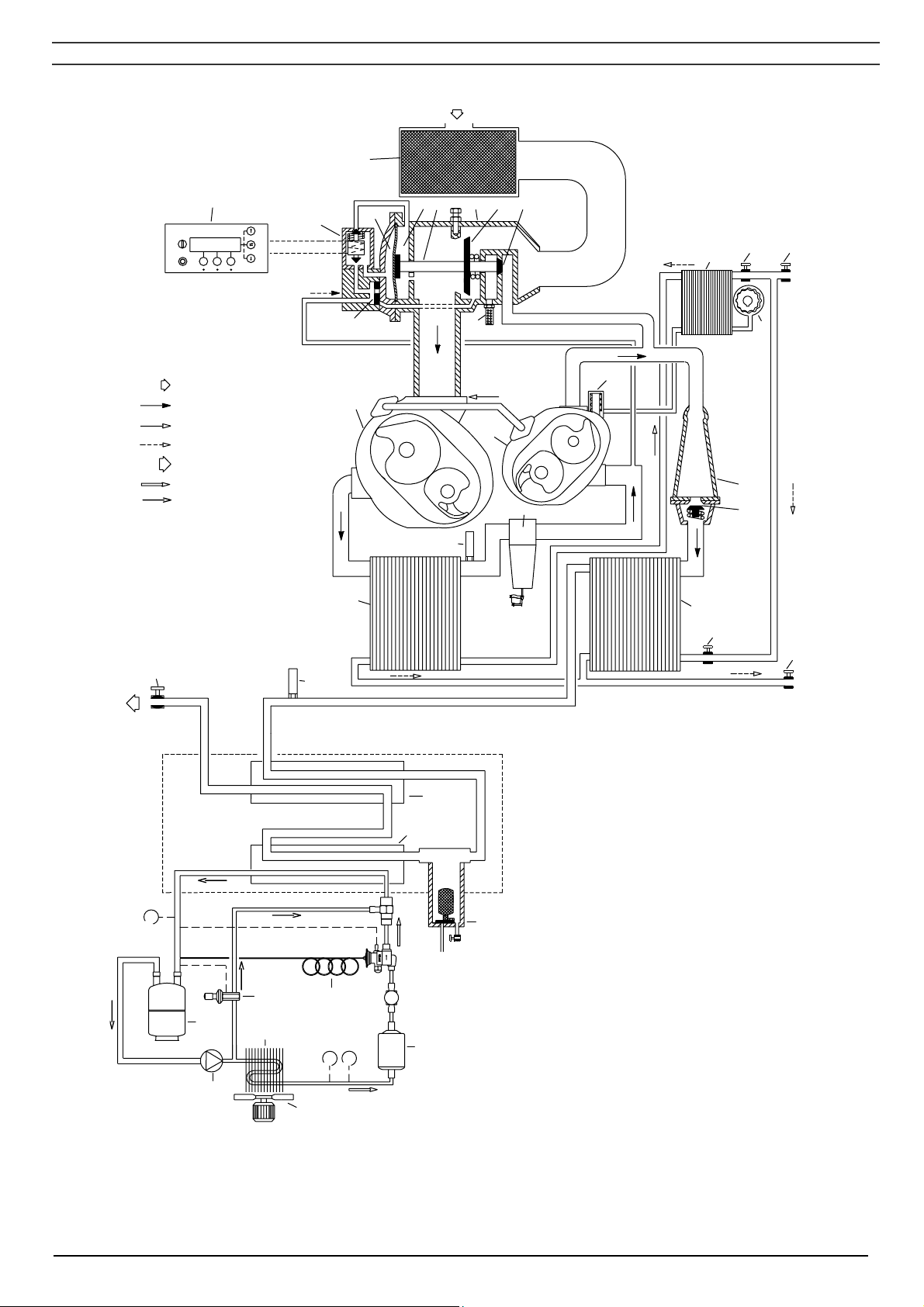
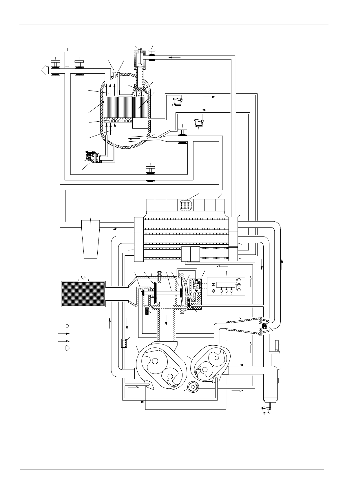
AF Air filter
AS Pulsation damper
AV Air outlet valve (customer’s installation)
CM Elektronikon regulator
CV Check valve
Eh High-pressure compressor element
El Low-pressure compressor element
EWDi Electronic water drain, intercooler
FN1 Cooling fan
MTa Condensate trap, aftercooler
MTi Condensate trap, intercooler
OF Oil filter
OP Oil pump
SVh High-pressure safety valve
SVl Low-pressure safety valve
TV Load/no-load valve
UA Unloader
US Silencer
UV Unloading valve
Y1 Loading solenoid valve
1 Chamber
2 Plunger
3 Chamber
4 Diaphragm
5 Valve for (+) connection, pressure difference gauge
6 Valve for (-) connection, pressure difference gauge
7 Throttle valve, regeneration inlet air
8 Shut-off valve, hot regeneration inlet air
9 Strainer
10 Sealing sector, regeneration air inlet (unsaturated side)
11 Intercooler
12 Rotor
13 Fan motor, air coolers
14 Ejector
15 Aftercooler
16 Oil cooler
17 Electronic water drain, inlet air
18 Water separator, inlet air
19 Demister
20 Rotor sealing arrangement
21 Dry air outlet compartment
22 Regeneration air cooler
23 Regulating valve, oil cooler and intercooler water circuit
24 Regulating valve, aftercooler water circuit
25 Regulating valve, regeneration air cooler water circuit
26 IMD air inlet valve
27 IMD by-pass valve
28 IMD outlet valve
29 Electronic drains, regeneration air cooler
30 Water shut-off valve, water outlet (customer’s installation)
31 Shut-off valve, water inlet (customer’s installation)
Figs. 1.7 Flow diagram/regulating system, ZT Full-Feature with IMD dryer
2920 1472 03 16

Instruction book
1.6 Air dryer on Full-Feature
Full-Feature compressors are provided with a dryer which removes moisture from compressed air.
Two dryer types are available: a refrigerant-type dryer (ID dryer) and an adsorption-type dryer (IMD
dryer).
1.6.1 Compressors with an ID dryer (Figs. 1.6)
Compressed air circuit of the dryer
Compressed air enters heat exchanger (6) and is cooled by the outgoing dried air. Water in the
incoming air starts to condense. The air then flows through heat exchanger/evaporator (7) where the
refrigerant evaporates, causing the air to be further cooled to close to the evaporating temperature of
the refrigerant. More water in the air condenses. The cold air then flows through condensate trap (5),
where all the condensate is separated from the air. The condensate collects in the condensate trap
and is automatically drained. The cold, dried air flows through heat exchanger (6), where it is warmed
up by the incoming air.
Refrigeration circuit of the dryer
Compressor (M3) delivers high-pressure refrigerant gas, which flows through condenser (10) where
most of the refrigerant condenses.
The liquid flows through liquid refrigerant dryer/filter (13) to capillary tube (8). The refrigerant leaves
the capillary tube at evaporating pressure.
The refrigerant enters evaporator (7) where it withdraws heat from the compressed air by further
evaporation at constant pressure. The heated refrigerant leaves the evaporator and is sucked in by
the compressor.
1.6.2 Compressors with an IMD dryer (Figs. 1.7)
Air drying circuit of the dryer
Wet air from the aftercooler (15) enters the dryer through inlet valve (26) and the nozzle of ejector
(14). The air leaving the aftercooler is normally saturated.
In the demister (18), water droplets are removed from the air. The air is then led through rotor (19),
which adsorbs the water vapour. The dried air leaves the dryer through outlet valve (28).
Regeneration air circuit of the dryer
Hot unsaturated regeneration air flows through shut-off valve (8) and throttle valve (7) through the wet
rotor channels (12). Since the hot air has a lower vapour pressure than the wet rotor channels, it will
dry the rotor.
The hot saturated air is then cooled down in regeneration air cooler (22) and led to the suction
chamber of ejector (14), where it is mixed with the wet compressed air from the compressor
aftercooler.
Drain system of the dryer
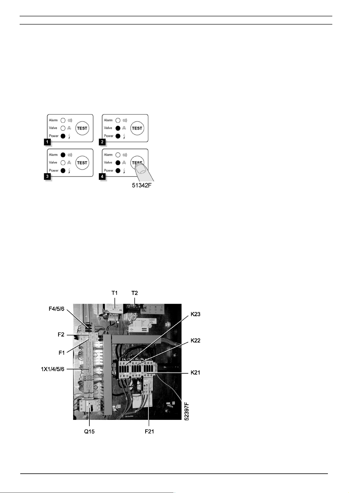
The condensate is collected in three EWD (Electronic Water Drains-Fig. 1.8). A sensor continuously
measures the liquid level. As soon as the collector is filled up to a certain level, the outlet opens,
discharging the condensate. When the collector has been emptied, the outlet closes quickly without
wasting compressed air.
If the controller registers a malfunction, the red alarm LED (Fig. 1.8) starts flashing and the electronic
drain valve will automatically change to the alarm mode, opening and closing the valve according to a
built-in sequence. This condition continues until the fault is remedied. If the fault is not remedied
automatically, maintenance is required. Consult your Atlas Copco Customer Centre.
2920 1472 03 17
Instruction book
Testing the EWD
Functional test
Briefly press the TEST button (Fig. 1.8) and check that the valve opens for condensate discharge.
Checking the alarm signal
- Press the test button for at least 1 minute
- Check that the alarm LED flashes
- Release the test button.
Fig. 1.8 Control panel of Electronic Water Drain (EWD)
1.7 Electrical system
The system mainly includes:
- Elektronikon regulator (1-Fig. 1.1)
- Emergency stop button (S3-Fig. 1.1)
- Electric cabinet (Fig. 1.9)
- Drive motor (M1-Fig. 1.2)
- Pressure and temperature sensors
F1/2 Fuses
F4/5/6 Fuses
F21 Overload relay, drive motor
K21 Line contactor
K22 Star contactor
K23 Delta contactor
Q15 Circuit breaker, fan motor (on ZT)
T1 Main transformer
T2 Transformer, control circuit
1X1/4/5/6 Terminal strips
Fig. 1.9 Electric cabinet, typical
example
2920 1472 03 18

Instruction book
1.8 Elektronikon control system
In general, the Elektronikon regulator has following functions:
- automatic control of the compressor
- protecting the compressor
- monitoring components - service warning
- automatic restart after voltage failure
1.8.1 Automatic control of the compressor
The regulator maintains the net pressure between programmable limits by automatically loading and
unloading the compressor. A number of programmable settings, e.g. the unloading and loading
pressures, the minimum stop time and the maximum number of motor starts are taken into account.
The regulator stops the compressor whenever possible to reduce the power consumption and restarts
it automatically when the net pressure decreases. In case the expected stopping period is too short,
the compressor is kept running to prevent too-short standstill periods.
Warning
A number of time-based automatic start/stop commands may be programmed. Take into account that
a start command will be executed (if programmed and activated), even after manually stopping the
compressor.
1.8.2 Protecting the compressor
Shut-down and motor overload
Several temperature and pressure sensors are provided on the compressor. If one of these
measurements (temperature at LP element outlet, temperature at HP element outlet, intercooler
pressure as well as oil pressure) exceeds the programmed shut-down level, the compressor will be
stopped. This will be indicated on the control display.
The compressor will also be stopped in case of overload of the drive motor.
Consult the safety precautions as mentioned in section 4 and remedy the trouble. See also the User
manual for Elektronikon regulator, section “Status data menu”.
Shut-down warning
If the regulator detects a temperature or pressure just below the programmed shut-down level, this will
be indicated on the control panel to warn the operator before the shut-down level is reached.
The message disappears as soon as the warning condition disappears.
1.8.3 Service warning
A number of service operations are grouped (called Level A, B, C, ...). Each level has a programmed
time interval. If a time interval is exceeded, a message will appear on display (2-Fig. 1.10) to warn the
operator to carry out the service actions belonging to that level. See section 4.
1.8.4 Automatic restart after voltage failure
The regulator has a built-in function to automatically restart the compressor if the voltage is restored
after voltage failure. For compressors leaving the factory, this function is made inactive. If desired,
the function can be activated. Consult Atlas Copco.
2920 1472 03 19
Instruction book
Warning
If activated and provided the module was in the automatic operation mode, the compressor will
automatically restart if the supply voltage to the module is restored within a programmed time period.
The power recovery time (the period within which the voltage must be restored to have an automatic
restart) can be set between 1 and 255 seconds or to Infinite. If the power recovery time is set to
Infinite, the compressor will always restart after a voltage failure, no matter how long it takes to restore
the voltage. A restart delay can also be programmed, allowing e.g. two compressors to be restarted
one after the other.
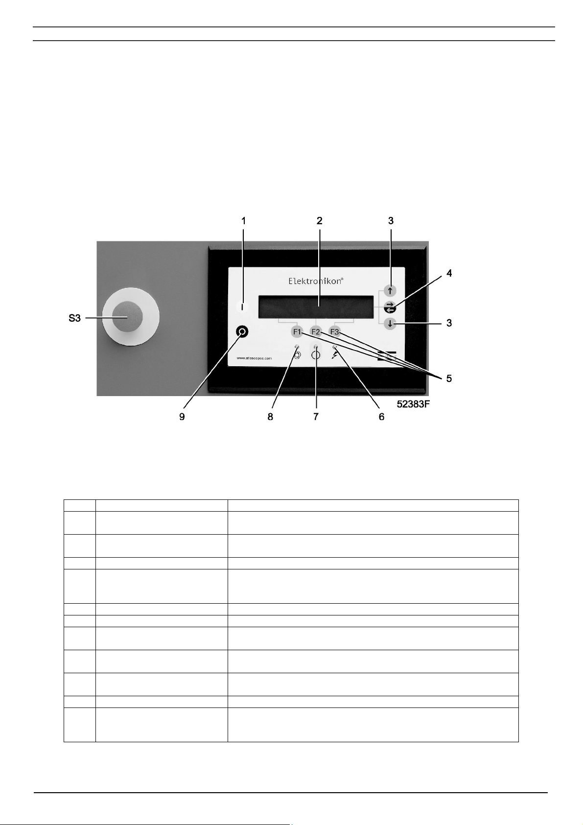
1.9 Control panel
Fig. 1.10 Control panel
1.9.1 LEDs/buttons/keys
Ref. Designation Function
1 Start button Push button to start the compressor. LED (8) lights up,
indicating that the Elektronikon regulator is operative.
2 Display Indicates messages concerning the compressor operating
condition, a service need or a fault.
3 Scroll keys Keys to scroll upwards or downwards through the display.
4 Tabulator key Key to select the parameter indicated by a horizontal arrow.
Only the parameters followed by an arrow pointing to the right
are accessible for modifying.
5 Function keys Keys to control and program the compressor. See section 1.9.3.
6 Voltage on LED Indicates that the voltage is switched on.
7 General alarm LED Is alight if a shut-down warning condition exists. See section
1.8.2.
7 General alarm LED Blinks if a shut-down condition exists, if an important sensor is
out of order or after an emergency stop. See section 1.8.2.
8 Automatic operation LED Indicates that the regulator is automatically controlling the
compressor.
9 Stop button Push button to stop the compressor. LED (8) goes out.
S3 Emergency stop button Push button to stop the compressor immediately in case of
emergency. After remedying the trouble, unlock the button by
pulling it out.
2920 1472 03 20
 Loading...