


GA90
Atlas Copco GA90, GA110, GA132, GA160, GA200 Instruction Book
...
Atlas Copco Stationary Air Compressors
Important
1. This book applies to the compressors from serial number
AIF-024 378 onwards.
2. This book must be used together with the "User manual for Elektronikon
®
regulator", printed matter no.
2920 1291 0x.
*2920125102*
No. 2920 1251 02
Registration code: APC G ≥ 90/'99 / 38 / 995
Replaces 2920 1251 01
2000-01
GA90 - GA110 - GA132 - GA160 - GA200 - GA250 - GA315
GA90 W - GA110 W - GA132 W - GA160 W - GA200 W GA250 W - GA315 W
Instruction Book
• Copyright 2000, Atlas Copco Airpower n.v., Antwerp, Belgium.
Any unauthorized use or copying of the contents or any part thereof is prohibited. This applies
in particular to trademarks, model denominations, part numbers and drawings.
• This instruction book meets the requirements for instructions specified by the machinery directive
98/37/EC and is valid for CE as well as non-CE labelled machines

2920 1251 02
2
Instruction book
This instruction book describes how to handle the machines to ensure safe operation, optimum efficiency and long service life.
Read this book before putting the machine into operation to ensure correct handling, operation and proper maintenance from the
beginning. The maintenance schedule comprises measures for keeping the machine in good condition.
Keep the book available for the operator and make sure that the machine is operated and that maintenance is carried out according
to the instructions. Record all operating data, maintenance performed, etc. in an operator's logbook available from Atlas Copco.
Follow all relevant safety precautions, including those mentioned on the cover of this book.
Repairs must be carried out by trained personnel from Atlas Copco who can be contacted for any further information.
In all correspondence mention the type and the serial number, shown on the data plate.
For all data not mentioned in the text, see sections "Preventive maintenance schedule" and "Principal data".
The company reserves the right to make changes without prior notice.
Page
5 Adjustments and servicing procedures . . . . . . . . . . . . . . 32
5.1 Air filters . . . . . . . . . . . . . . . . . . . . . . . . . . . . . . . . . . . . 32
5.2 Coolers . . . . . . . . . . . . . . . . . . . . . . . . . . . . . . . . . . . . . 32
5.3 Safety valve. . . . . . . . . . . . . . . . . . . . . . . . . . . . . . . . . . 32
6 Problem solving . . . . . . . . . . . . . . . . . . . . . . . . . . . . . . . . . . 33
7 Principal data . . . . . . . . . . . . . . . . . . . . . . . . . . . . . . . . . . . . 33
7.1 Readings on display . . . . . . . . . . . . . . . . . . . . . . . . . . . 33
7.2 Programmable settings . . . . . . . . . . . . . . . . . . . . . . . . . 33
7.3 Settings of safety valves . . . . . . . . . . . . . . . . . . . . . . . . 34
7.4 Settings of overload relay, circuit breakers and fuses . 34
7.4.1 Motor overload relay and fuses for
GA/GA W - 50 Hz with ABB motors . . . . . . . 34
7.4.2 Motor overload relay and fuses for
GA/GA W - 60 Hz with ABB motors . . . . . . . 34
7.4.3 Motor overload relay and fuses for
GA/GA W - 60 Hz with Siemens motors . . . . 35
7.4.4 Fan motor circuit breakers for GA - 50 Hz . . . 36
7.4.5 Fan motor circuit breakers for GA - 60 Hz . . . 36
7.5 Compressor specifications . . . . . . . . . . . . . . . . . . . . . . 36
7.5.1 Reference conditions . . . . . . . . . . . . . . . . . . . . 36
7.5.2 Limitations . . . . . . . . . . . . . . . . . . . . . . . . . . . . 36
7.5.3 Specific data of GA/GA W 90 up to -160
7.5 bar - 50 Hz . . . . . . . . . . . . . . . . . . . . . . . . . 37
7.5.4 Specific data of GA/GA W 90 up to -160
10 bar - 50 Hz . . . . . . . . . . . . . . . . . . . . . . . . . . 37
7.5.5 Specific data of GA/GA W 90 up to -160
13 bar - 50 Hz . . . . . . . . . . . . . . . . . . . . . . . . . . 37
7.5.6 Specific data of GA/GA W 90 up to -160
100 psi - 60 Hz. . . . . . . . . . . . . . . . . . . . . . . . . 38
7.5.7 Specific data of GA/GA W 90 up to -160
125 psi - 60 Hz. . . . . . . . . . . . . . . . . . . . . . . . . 38
7.5.8 Specific data of GA/GA W 90 up to -160
150 psi - 60 Hz. . . . . . . . . . . . . . . . . . . . . . . . . 38
7.5.9 Specific data of GA/GA W 90 up to -160
200 psi - 60 Hz. . . . . . . . . . . . . . . . . . . . . . . . . 39
7.5.10 Specific data of GA/GA W 200 and -250
7.5 bar - 50 Hz. . . . . . . . . . . . . . . . . . . . . . . . . 39
7.5.11 Specific data of GA/GA W 200 and -250
10/13 bar - 50 Hz . . . . . . . . . . . . . . . . . . . . . . 39
7.5.12 Specific data of GA/GA W 200 up to -315
100 psi - 60 Hz. . . . . . . . . . . . . . . . . . . . . . . . . 40
7.5.13 Specific data of GA/GA W 200 up to -315
125 psi - 60 Hz. . . . . . . . . . . . . . . . . . . . . . . . . 40
7.5.14 Specific data of GA/GA W 200 up to -315
150 psi - 60 Hz. . . . . . . . . . . . . . . . . . . . . . . . . 40
7.5.15 Specific data of GA/GA W 250 and -315
200 psi - 60 Hz. . . . . . . . . . . . . . . . . . . . . . . . . 41
7.6 Conversion list of SI units into British/US units . . . . . 41
Contents
Page
1 Leading particulars . . . . . . . . . . . . . . . . . . . . . . . . . . . . . . . . 3
1.1 General description . . . . . . . . . . . . . . . . . . . . . . . . . . . . . 3
1.2 Elektronikon
®
control system . . . . . . . . . . . . . . . . . . . . . 3
1.2.1 Elektronikon regulator . . . . . . . . . . . . . . . . . . . . 3
1.2.2 Control panel . . . . . . . . . . . . . . . . . . . . . . . . . . . 7
1.2.3 Compressor control modes . . . . . . . . . . . . . . . . 8
1.2.4 External compressor status indication . . . . . . . . 8
1.2.5 External communication . . . . . . . . . . . . . . . . . . 8
1.3 Regulating system. . . . . . . . . . . . . . . . . . . . . . . . . . . . . . 8
1.3.1 Air flow. . . . . . . . . . . . . . . . . . . . . . . . . . . . . . . . 8
1.3.2 Condensate drain system . . . . . . . . . . . . . . . . . . 9
1.3.3 Oil system . . . . . . . . . . . . . . . . . . . . . . . . . . . . . . 9
1.3.4 Cooling system . . . . . . . . . . . . . . . . . . . . . . . . . 10
1.3.5 Regulating system . . . . . . . . . . . . . . . . . . . . . . 12
2 Installation . . . . . . . . . . . . . . . . . . . . . . . . . . . . . . . . . . . . . 14
2.1 Dimension drawings . . . . . . . . . . . . . . . . . . . . . . . . . . . 14
2.2 Installation proposal . . . . . . . . . . . . . . . . . . . . . . . . . . . 17
2.3 Electric cables . . . . . . . . . . . . . . . . . . . . . . . . . . . . . . . . 20
2.3.1 GA - 50 Hz . . . . . . . . . . . . . . . . . . . . . . . . . . . . 20
2.3.2 GA W - 50 Hz . . . . . . . . . . . . . . . . . . . . . . . . . 20
2.3.3 GA/GA W - 60 Hz (except for Canada/USA) . 20
2.3.4 GA/GA W - 60 Hz (Canada/USA) . . . . . . . . . 23
2.4 Pictographs . . . . . . . . . . . . . . . . . . . . . . . . . . . . . . . . . . 23
2.5 Cooling water requirements . . . . . . . . . . . . . . . . . . . . . 24
3 Operating instructions. . . . . . . . . . . . . . . . . . . . . . . . . . . . . 25
3.1 Preparation for initial start-up . . . . . . . . . . . . . . . . . . . 25
3.2 Before starting. . . . . . . . . . . . . . . . . . . . . . . . . . . . . . . . 26
3.3 Routine starting . . . . . . . . . . . . . . . . . . . . . . . . . . . . . . . 26
3.4 Starting after emergency stop or shut-down . . . . . . . . 26
3.5 During operation . . . . . . . . . . . . . . . . . . . . . . . . . . . . . . 27
3.5.1 Checking the display . . . . . . . . . . . . . . . . . . . . 27
3.6 Manual unloading/loading . . . . . . . . . . . . . . . . . . . . . . 28
3.7 Stopping . . . . . . . . . . . . . . . . . . . . . . . . . . . . . . . . . . . . 28
3.8 Taking out of operation. . . . . . . . . . . . . . . . . . . . . . . . . 28
4 Maintenance . . . . . . . . . . . . . . . . . . . . . . . . . . . . . . . . . . . . . 29
4.1 Preventive maintenance schedule for the compressor . 29
4.2 Motors . . . . . . . . . . . . . . . . . . . . . . . . . . . . . . . . . . . . . 30
4.2.1 Fan motors (GA only) . . . . . . . . . . . . . . . . . . . 30
4.2.2 Drive motor . . . . . . . . . . . . . . . . . . . . . . . . . . . 30
4.3 Oil specifications . . . . . . . . . . . . . . . . . . . . . . . . . . . . . 30
4.3.1 Roto-injectfluid . . . . . . . . . . . . . . . . . . . . . . . . 30
4.4 Oil change . . . . . . . . . . . . . . . . . . . . . . . . . . . . . . . . . . . 30
4.5 Oil filter change . . . . . . . . . . . . . . . . . . . . . . . . . . . . . . 30
4.6 Storage after installation . . . . . . . . . . . . . . . . . . . . . . . . 31
4.7 Service kits . . . . . . . . . . . . . . . . . . . . . . . . . . . . . . . . . . 32

2920 1251 02
3
Instruction book
1 LEADING PARTICULARS
1.1 General description
GA90 up to GA315 and GA90 W up to GA315 W are singlestage, oil-injected screw compressors, driven by an electric
motor and enclosed in a sound-insulated bodywork.
GA90 up to GA315 are air-cooled, abbreviated as "GA". GA90
W up to GA315 W are water-cooled, abbreviated as "GA W".
The compressors are available for a maximum working pressure
of:
- 7.5, 10 or 13 bar(e) for 50 Hz versions
- 107, 132, 157 or 200 psig for 60 Hz versions
GA and GA W include mainly:
- Air filter(s)
- One or two compressor elements 1)
- One or two unloaders 1)
- Air receiver/oil separator
- Air cooler
- Oil cooler(s)
- Drive motor
- Drive coupling
- Gear casing
- Elektronikon® control system
- Safety valves
Energy recovery
The compressors can easily be provided with the Atlas Copco
energy recovery systems to recover the major part of the
compression heat in the form of hot water.
Heavy-duty filters
A heavy-duty filter kit is available as option allowing the
compressor to operate in heavily contaminated surroundings.
Oil/water separation
Atlas Copco has oil/water separators (type OSM), especially
designed for GA/GA W compressors, to separate oil from
condensate to meet the requirements of the local environmental
codes.
1.2 Elektronikon® control system
1.2.1 Elektronikon regulator
1.2.1.1 Automatic control of compressor operation
The regulator maintains the net pressure between programmable
limits by automatically loading and unloading the compressor.
A number of programmable settings, e.g. the unloading and
loading pressures, the minimum stop time and the maximum
number of motor starts are taken into account.
The regulator stops the compressor whenever possible to reduce
the power consumption and restarts it automatically when the
net pressure decreases. In case the expected unloading period
is too short, the compressor is kept running to prevent tooshort standstill periods.
Warning
A number of time-based automatic start/stop commands may
be programmed. 2) Take into account that a start command
will be executed (if programmed and activated), even after
manually stopping the compressor.
1.2.1.2 Protecting the compressor
Shut-down
If the temperature at the outlet of the compressor elements
exceeds the programmed shut-down level, the compressor will
be stopped. This will be indicated on display (4-Fig. 3a) and
general alarm LED (3) will blink. The compressor will also be
stopped in case of overload of the drive motor and on GA also
in case of fan motor overload.
Remedy the trouble and reset the message on the display before
restarting. See "User manual for Elektronikon® regulator",
section "Submenu ST ATUS DAT A".
Shut-down warning
Before the shut-down level for the compressor element outlet
temperature is reached, a message will appear on display (4Fig. 3a) and general alarm LED (3) will light up, to warn the
operator that the shut-down warning level is exceeded. The
shut-down warning level is a programmable setting below the
shut-down level.
The message disappears as soon as the cause of the trouble is
remedied.
1.2.1.3 Monitoring components subject to service
The regulator continuously monitors the oil, oil filters, oil
separator, drive motor grease and air filters. Each input is
compared to programmed maximum time intervals or pressure
drops. If these limits are exceeded, a message will appear on
display (4-Fig. 3a) to warn the operator to replace the indicated
component, to change the oil or to grease the motor as the case
may be.
1) GA/GA W 90 up to -160 are equipped with one compressor
element and unloader, all other types have two compressor
elements and unloaders.
2) This funcion is called the Timer function. See "User manual for
Elektronikon regulator", section "Submenu TIMERS".
2920 1251 02
4
Instruction book
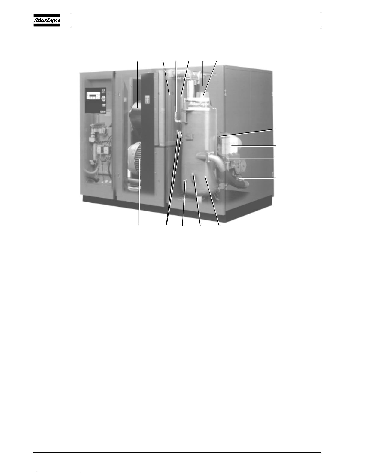
Fig. 1a GA90
AF. Air filter
AR. Air receiver/oil separator
Ca. Air cooler
Co. Oil cooler
CV. Check valve
DP1. Oil drain plug, air receiver
DP4. Oil drain plug, oil cooler
E. Compressor element
FC1. Oil filler plug
FC2. Oil filler plug (only to be used at
initial start-up)
FN2. Fan
Gl. Oil level indicator
M1. Drive motor
OF . Oil filters
SV. Safety valve
UA. Unloader
Vp. Minimum pressure valve
Vs. Oil stop valve
Y1. Loading solenoid valve
Figs. 1. GA90 and GA110 W
50314F
M1 DP1/4
GL
FC1 AR
UA
OF
E
CV
AF FN2CaSV
Co
Vp
2920 1251 02
5
Instruction book
1.2.1.4 Automatic restart after voltage failure
For compressors leaving the factory, this function is made
inactive. If desired, the function can be activated. Consult
Atlas Copco.
Warning
If activated and provided the regulator was in the automatic
operation mode and the compressor control mode (local, remote
1 or remote 2 - see section 1.2.3) was not changed during the
voltage failure, the compressor will automatically restart if the
supply voltage to the module is restored within a programmed
time period (this time period is called the power recovery
time).
The power recovery time can be set between 1 and 254 seconds
or to 0. If the power recovery time is set to 0, the compressor
will always restart after a voltage failure, no matter how long it
takes to restore the voltage.
1.2.1.5 Permissive start
After a start command (either automatic start by the electronic
regulator or manual start), the permissive start function is
operating: if the oil injection pressure at the compressor
elements exceeds the programmed level, the compressor will
not start (indicated as <<Start failure>>). See "User manual
for Elektronikon regulator", section "Programmable settings
for GA90/315".
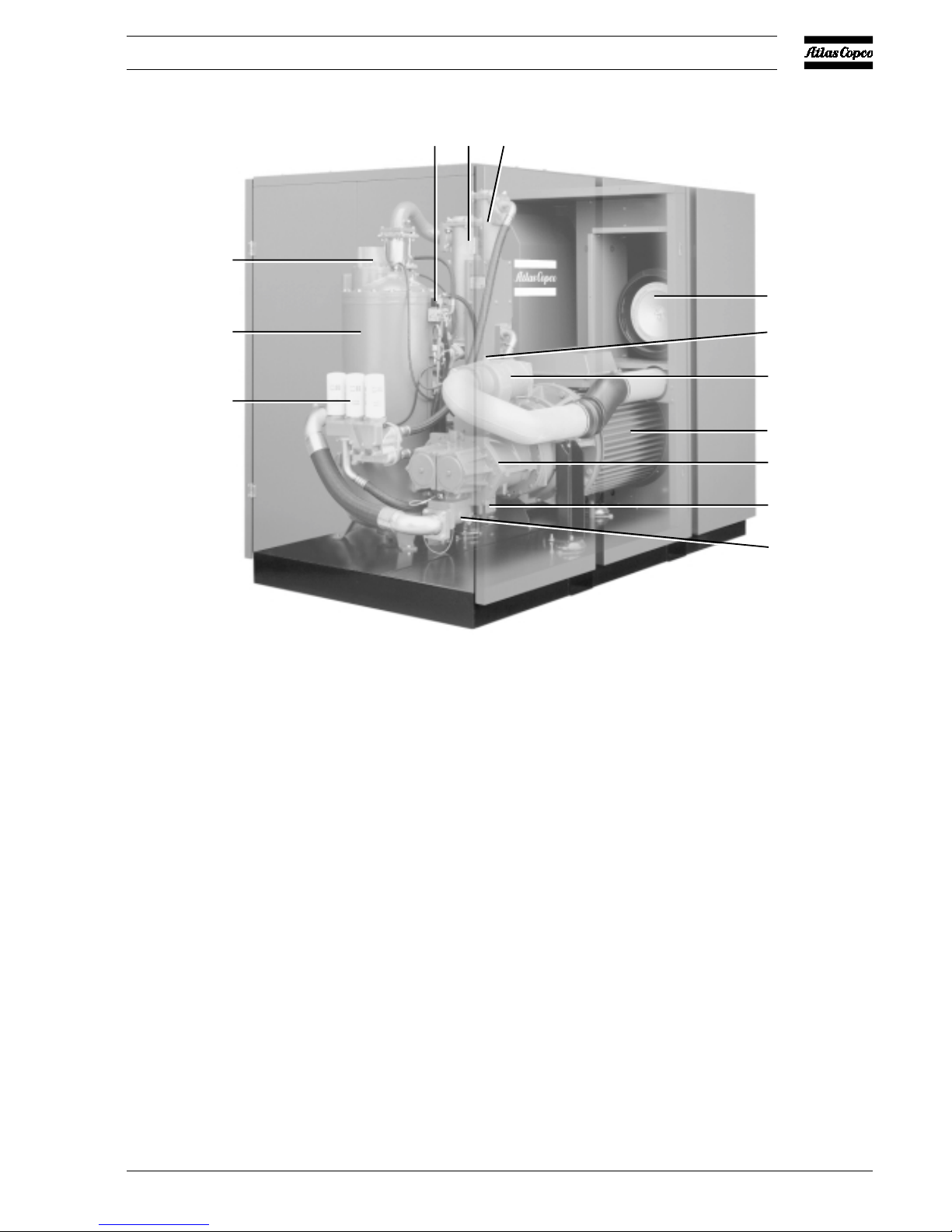
Fig. 1b GA110 W
50315F
Y1
Ca Co
Vp
AR
OF
M1
E
Vs
CV
AF
FC2
UA
2920 1251 02
6
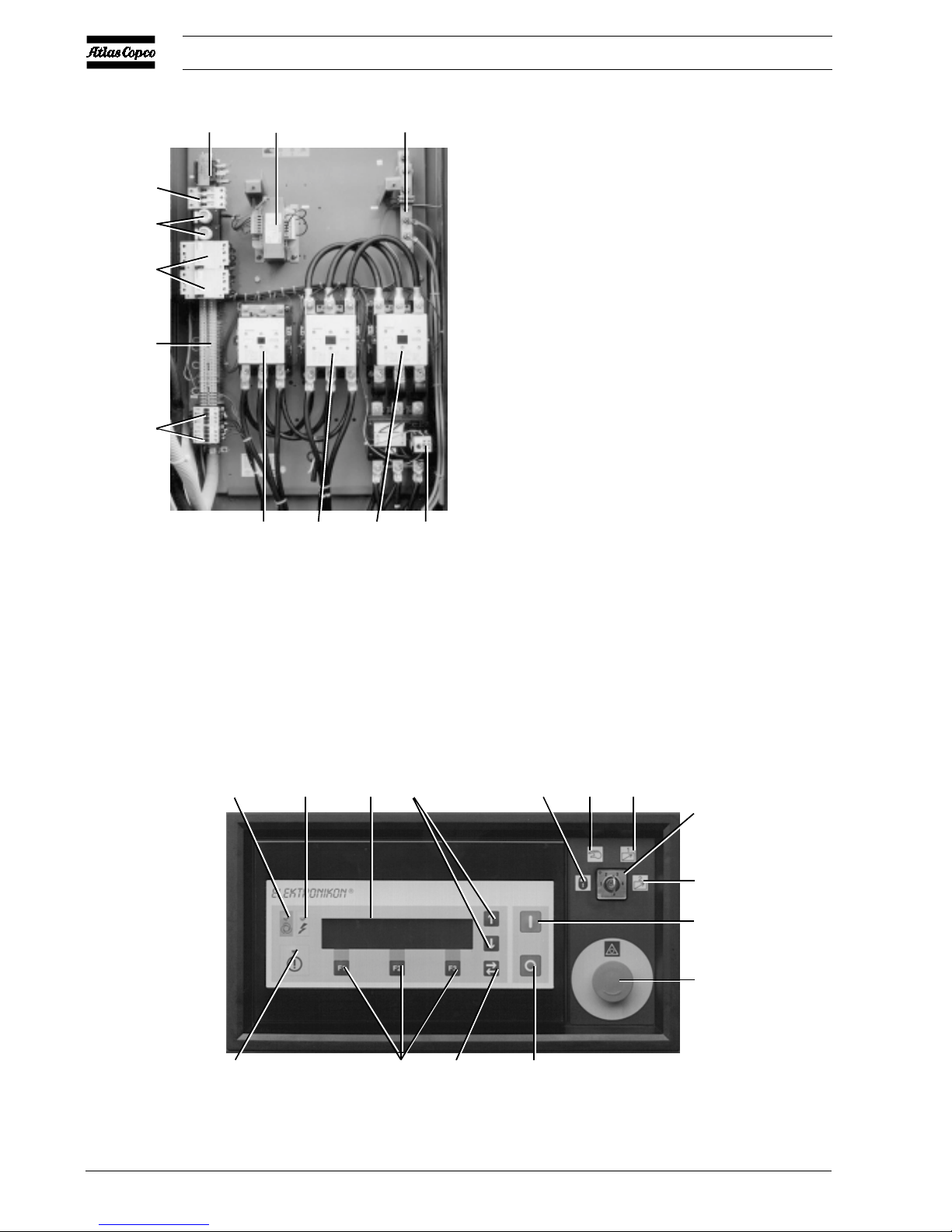
Instruction book
F1/F2. Fuses
F3/F5. Circuit breakers
F21. Overload relay, drive motor (M1)
K15/16. Fan motor contactors 1)
K21. Line contactor
K22. Star contactor
K23. Delta contactor
Q15/16. Fan motor circuit breakers 1)
T1/T2. Transformers
1X1. T erminal strip
1X3. Earthing rail
1) One contactor/circuit breaker on GA90 and -1 10, two
contactors/circuit breakers on GA132 up to -315, not
provided on GA W.
Fig. 2. Electric cabinet (typical example)
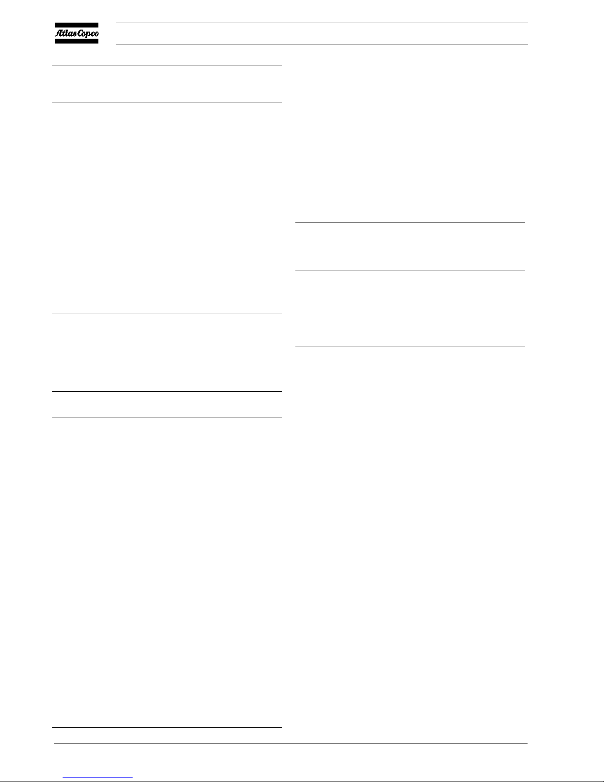
Fig. 3a. Control panel
K22 K23 K21
F21
50309F
T2
T1
1X3
F3/4/5
F1/2
Q15/16
1X1
K15/16
12
46
10 11
12
13
S5
8
S2
3
57
9
50749F

2920 1251 02
7
Instruction book
1.2.2 Control panel (Fig. 3a)
Indicators, keys and buttons
Ref. Designation
1 Automatic operation Indicates that the regulator is auto-
LED matically controlling the com-
pressor: the compressor is loaded,
unloaded, stopped and restarted
depending on the air consumption
and the limitations programmed in
the regulator.
2 Voltage on LED Indicates that the voltage is
switched on.
3 General alarm LED Is alight if a shut-down warning
condition exists. See section 1.2.1.
Blinks if a shut-down condition
exists, if a sensor used to protect
the compressor is out of order or
after an emergency stop. See
section 1.2.1.
4 Display Indicates messages concerning the
compressor operating condition, a
service need or a fault. See "User
manual for Elektronikon
regulator" sections "Submenu
STATUS DATA" and "Submenu
SERVICE".
Ref. Designation
5 Function keys Keys to control and program the
compressor. See below.
6 Scroll keys Keys to scroll through the display.
7 Tabulator key Key to go to the next field of the
display.
8 Start button Push button to start the
compressor. LED (1) lights up
indicating that the regulator is
operative (in automatic operation).
The LED goes out after unloading
the compressor manually.
9 Stop button Push button to stop the
compressor. LED (1) goes out.
The compressor will run unloaded
for 30 seconds before stopping.
S2 Emergency stop Push button to stop the compressor
button immediately in case of emergency .
After remedying the trouble,
unlock the button by turning it
anti-clockwise.
S5 Control mode switch Key switch to select the
compressor control modes. See
section 1.2.3.
Selecting a menu
To facilitate controlling the compressor , menu-driven programs
are implemented in the Elektronikon regulator. Use function
keys (5) to select the menus to program and monitor the
compressor. The "User manual for Elektronikon regulator"
deals elaborately with all regulator functions.
Function keys
The functions of the keys vary depending on the displayed menu.
The actual function is indicated just above the relevant key.
The most common functions are listed below:
Designation Function
(4-Fig. 3a)
Add T o add compressor start/stop commands (day/
hour)
Cancel To cancel a programmed setting when
programming parameters
Delete T o delete compressor start/stop commands
Limits To show limits for a programmable setting
List To list programmed start/stop commands
(day/hour)
Compressor outlet 7.0 bar
Automatically loaded
Menu Show More Unload
F1 F2 F3
Fig. 3b. Example of the main display
Status data
↓
Main Screen Select
F1 F2 F3
Fig. 3c. Example of a main menu
2920 1251 02
8
Instruction book
Designation Function
(4-Fig. 3a)
Load T o load the compressor manually
Main Screen To return from a menu to the main display
(Fig. 3b)
Menu Starting from the main display (Fig. 3b), to
initiate the main menu (Fig. 3c) which gives
access to submenus
Starting from a submenu, to return to the main
menu (Fig. 3c)
Modify T o modify programmable settings
Show More T o have a quick look at the compressor status
Program To program modified settings
Reset To reset a timer or message
Return To return to a previously shown option or
menu
Select To select a submenu or to read more details
of a selection shown on the display
Unload To unload the compressor manually
1.2.3 Compressor control modes
Key switch (S5-Fig. 3a) allows the operator to select four control
modes:
Key position Compressor control mode
10 Compressor off.
11 Local control mode (remote control mode
is made inactive):
- The compressor can only be controlled
by the buttons on the control panel.
- The compressor can be started and
stopped via function Timer (see section
1.2.1), if programmed and activated.
12 Remote control mode 1 (local control is
made inactive):
- The compressor can only be started and
stopped by an ES100 sequence selector
or by external switches. Do not use
maintained-action buttons in case of
remote starting/stopping.
- Compressor start/stop commands via
function T imer (see section 1.2.1) are still
possible, if programmed and activated.
- Emergency stop button (S2) remains
active.
13 Remote control mode 2. The compressor
can be controlled by an ES-type controller or
by computer. Consult Atlas Copco.
Important
- The regulator will only react to a new control mode if the
new position of the control mode switch is maintained for
3 seconds.
- To avoid unauthorized switching over to another control
mode, take out the key after selecting the required mode.
1.2.4 External compressor status indication
Terminal strip (1X1-Fig. 2) is provided with auxiliary contacts
for external indication of:
Indication Relay Terminals Max. load
on strip
1X1
Automatic operation K06 50-51 10 A / 230 V AC
W arning K07 52-53 10 A / 230 V AC
Shut-down K08 54-55 10 A / 230 V AC
Control mode
REMOTE 1 -- 56-57 10 A / 230 V AC
Warning
Stop the compressor and switch off the voltage before
connecting external equipment.
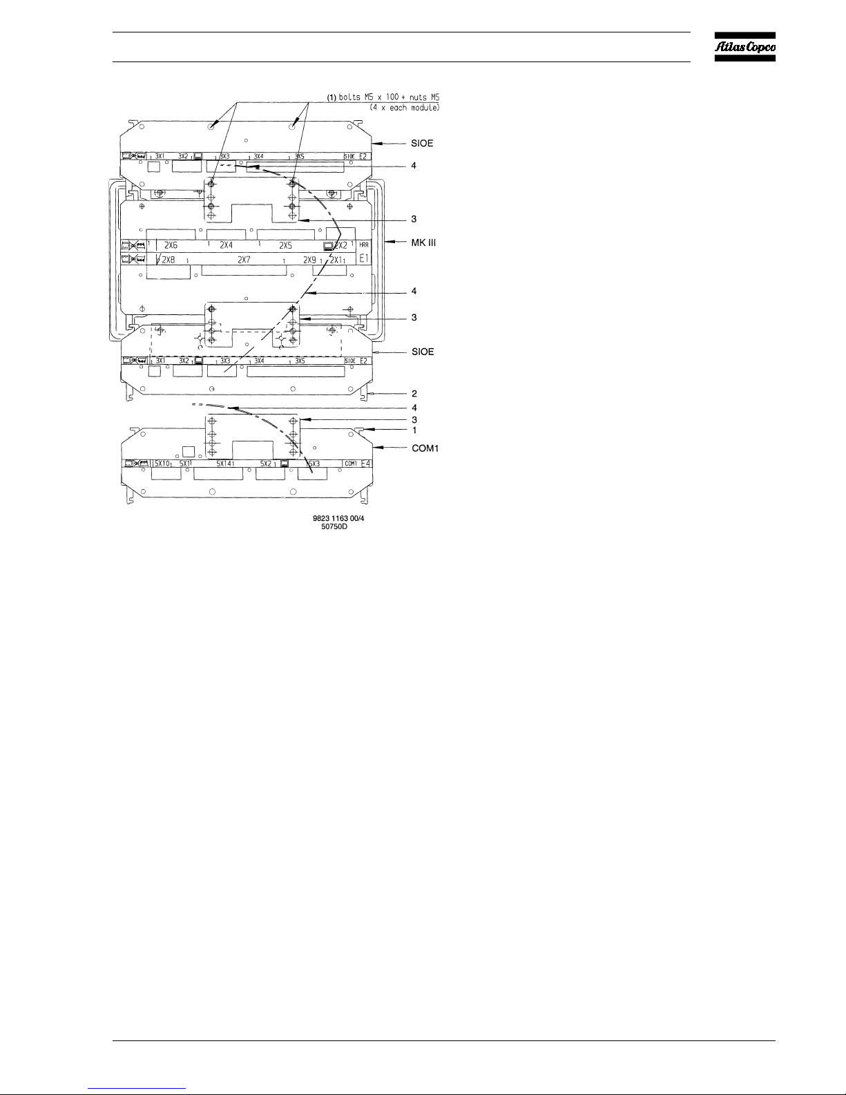
1.2.5 External communication
If it is desired to connect the compressor to an Atlas Copco ES
system (e.g. to an ES100 sequence selector), an optional
communication module (COM1) needs to be installed.
Installation (Fig. 4)
1. Fit the communication module (COM1) and fix it using
plate (3).
2. Connect the 24V power supply from terminals (11 and
12) of terminal strip (1X1) to connector (5X1) of
communication module (COM1).
3. Connect an earth cable between module (COM1) and the
module of the regulator.
4. Connect the cable delivered with the COM1 module from
connector (5X3) of the COM1 module to a free ..X2
connector on a module of the compressor regulator.
5. Consult Atlas Copco to check the installation and to have
the communication software loaded.
1.3 Regulating system (Figs. 5)
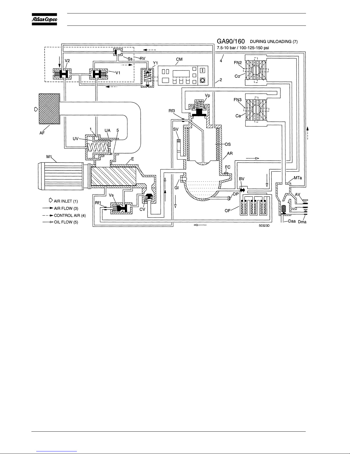
1.3.1 Air flow
GA/GA W 90 up to -160
Air drawn through filter (AF) and unloader (UA) is compressed
2920 1251 02
9
Instruction book
in compressor element (E). Compressed air and oil are
discharged to air receiver/oil separator (AR) via check valve
(CV). In the oil separator compressed air is separated from the
oil. The air is blown via minimum pressure valve (Vp) to air
cooler (Ca). The cooled air is discharged through moisture
trap (MTa) and outlet valve (AV) towards the air net.
Check valve (CV) prevents blow-back of compressed air.
GA/GA W 200 up to -315
Air drawn through filters (AF) and unloaders (UA1 and UA2)
is compressed in compressor elements (E1 and E2).
Compressed air and oil are discharged to air receiver/oil
separator (AR) via check valves (CV1 and CV2). In the oil
separator compressed air is separated from the oil. The air is
blown via minimum pressure valve (Vp) to air cooler (Ca).
The cooled air is discharged through moisture trap (MT a) and
outlet valve (AV) towards the air net.
Check valves (CV1 and CV2) prevent blow-back of compressed
air.
All GA/GA W
Minimum pressure valve (Vp) prevents the receiver pressure
from dropping below a minimum pressure. The valve has a
built-in check valve.
1.3.2 Condensate drain system
A moisture trap (MTa) is installed downstream of the air cooler
to prevent condensate from entering the air outlet pipe. The
trap is provided with a float valve for automatically draining
condensate (Daa) and with a manual drain valve (Dma).
1.3.3 Oil system
GA/GA W 90 up to -160
Air pressure forces the oil from receiver (AR) through oil
cooler(s) (Co), filters (OF) and valve (Vs) to compressor
element (E) and the lubrication points.
COM1. Communication module
MKIII. Electronic regulator
SIOE. Expansion modules (upper module not always
installed)
1. Guide
2. Slot
3. Plate
4. Cable
Fig. 4. Installation of communication module (typical
example)
2920 1251 02
10
Instruction book
Oil stop valve (Vs) prevents compressor element (E) from
flooding with oil when the compressor is stopped.
Valve (BV) by-passes oil cooler(s) (Co) when starting the
compressor from cold condition to ensure rapid warming of
the oil to normal working temperature.
GA/GA W 200 up to -315
Air pressure forces the oil from receiver (AR) through oil
cooler(s) (Co), filters (OF) and valves (Vs1 and Vs2) to
compressor elements (E1 and E2) and the lubrication points.
Oil stop valves (Vs1 and Vs2) prevent compressor elements
(E1 and E2) from flooding with oil when the compressor is
stopped.
Valves (BV) by-pass oil cooler(s) (Co) when starting the
compressor from cold condition to ensure rapid warming of
the oil to normal working temperature.
All GA/GA W
In receiver (AR) most of the oil is removed from the air
centrifugally. Almost all of the remaining oil is removed by
separator element (OS).
1.3.4 Cooling system
The system includes air cooler (Ca) and oil cooler (Co) (GA
W 132 up to -315 have two oil coolers).
On GA, the coolers are cooled by fans (FN2/3) (GA90 and 110 are provided with one fan). GA W are provided with a
cooling water system.
Fig. 5a GA90 up to -160 during unloading (7.5-10 bar/100-125-150 psi)
2920 1251 02
11
Instruction book
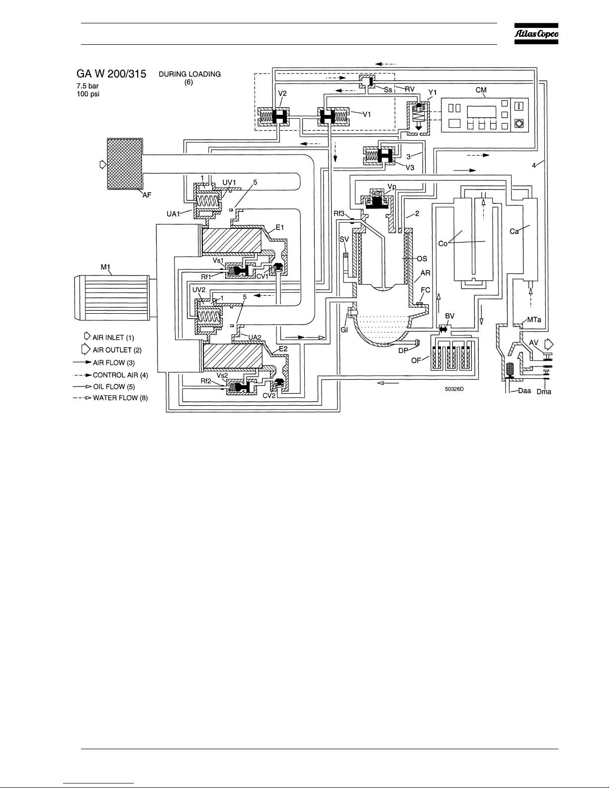
AF . Air filter(s)
AR. Air receiver/oil separator
AV. Air outlet valve
BV. Thermostatic by-pass valve(s),
oil cooler(s)
Ca. Air cooler
CM. Elektronikon® regulator
Co. Oil cooler(s)
CV. Check valve
CV1. Check valve
CV2. Check valve
Daa. Automatic condensate drain
outlet
Dma. Manual condensate drain valve
DP1. Drain plug, oil
E. Compressor element
E1. Compressor element
E2. Compressor element
FC. Filler plug, oil
FN2/3. Fans
Gl. Oil level indicator
MTa. Moisture trap
M1. Drive motor
OF . Oil filters
OS. Oil separator element
Rf1/3. Restrictors
R V. Regulating valve
Ss. Pressure selector valve
SV. Safety valve
UA. Unloader
UA1. Unloader
UA2. Unloader
UV. Unloading valve
UV1. Unloading valve
UV2. Unloading valve
Vp. Minimum pressure valve
Vs. Oil stop valve
Vs1. Oil stop valve
Vs2. Oil stop valve
V1. Control valve for unloading
valve
V2. Vent valve
V3. Vent valve 1)
Y1. Loading solenoid valve
1. Chamber
2. Flexible, control air or blowoff air
3. Flexible, blow-off air
4. Flexible, control air
5. By-pass hole, unloader
1) For GA/GA W 90 up to -160: only provided on 13 bar/200 psi versions
Figs. 5 Regulating systems
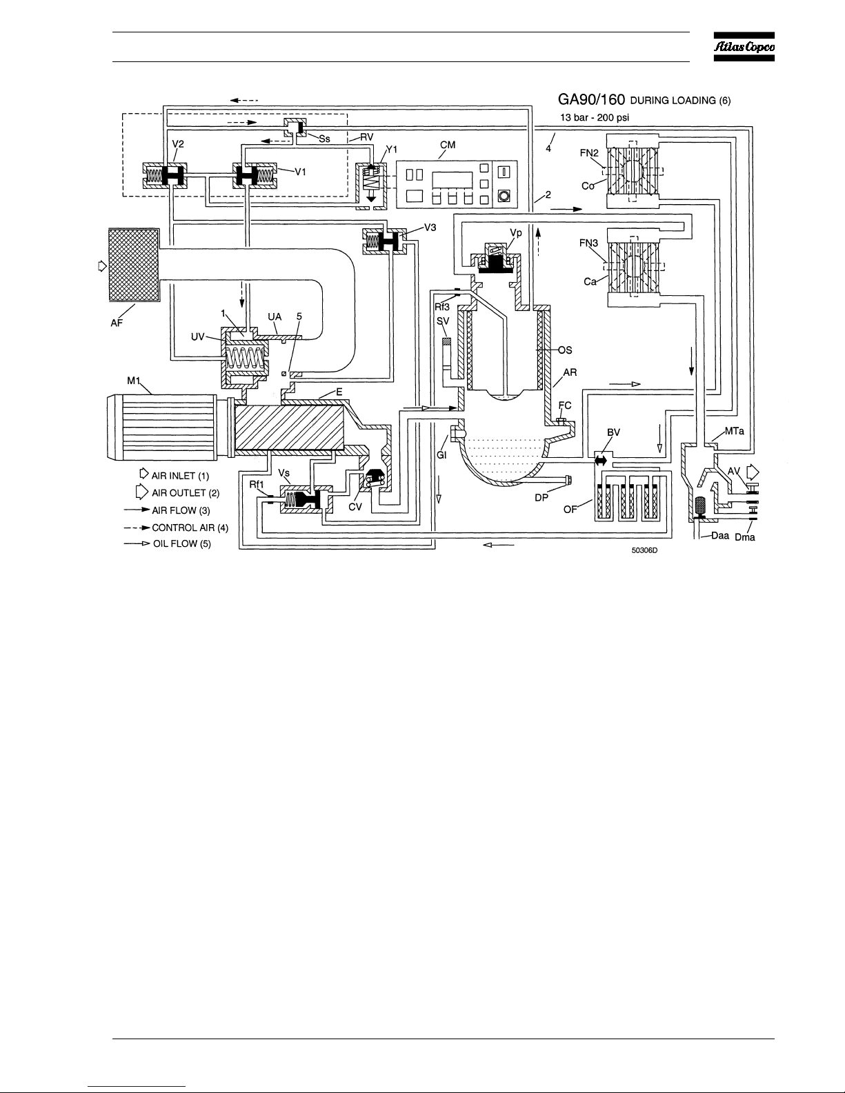
Fig. 5b GA90 up to -160 during loading (13 bar / 200 psi)
2920 1251 02
12
Instruction book
1.3.5 Regulating system
The system is controlled by Elektronikon® regulator (CM)
which keeps the net pressure within programmable pressure
limits by automatically loading and unloading the compressor
depending on the air consumption.
1.3.5.1 Unloading
If the air consumption is less than the air delivery of the
compressor, the net pressure increases. When the net pressure
reaches the upper limit of the working pressure (unloading
pressure), solenoid valve (Y1) is de-energized. The plunger of
the valve moves downwards by spring force:
GA/GA W 90 up to -160
1. Control pressure is fed via flexible (2) and selector valve
(Ss) through solenoid valve (Y1) to valves (V1 and V2).
2. The plungers of valves (V1 and V2) move against spring
force.
3. Control pressure present in chamber (1) of unloader (UA)
is vented to atmosphere through valve (V1). Unloading
valve (UV) closes by spring force.
4. Receiver pressure is released to unloader (UA):
- through flexible (2) and valve (V2)
- on 13 bar/200 psi compressors also through valve (V3)
as this valve is kept open by air from the outlet of
compressor element (E)
5. As the receiver pressure decreases, selector valve (Ss)
switches over.
6. On 13 bar/200 psi compressors, as the pressure at the
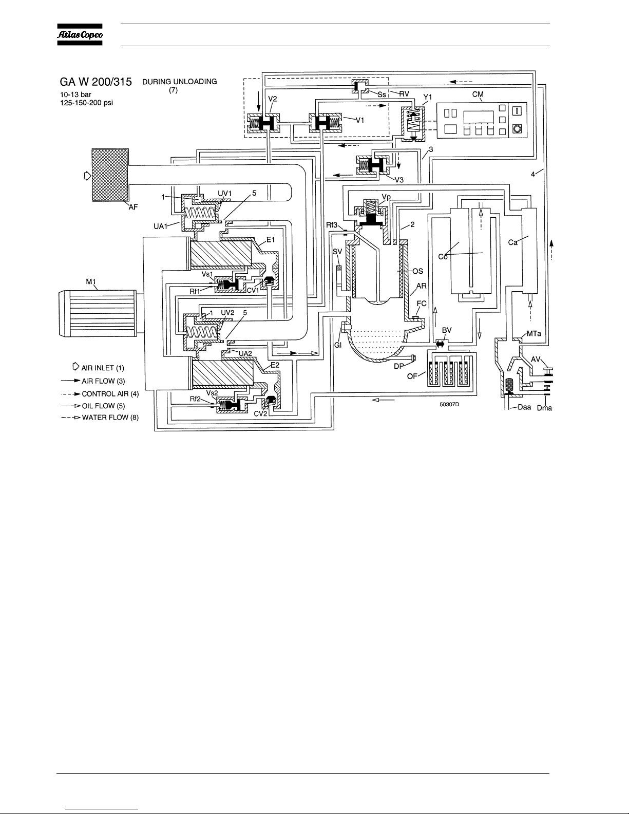
Fig. 5c GA W 200 up to -315 during unloading (10-13 bar/125-150-200 psi)
2920 1251 02
13
Instruction book
outlet of compressor element (E) decreases, valve (V3)
closes by spring force and stops blowing off air.
7. Valve (V2) allows the small flow of air, which remains
drawn in through by-pass hole (5), to blow off from
receiver (AR) via flexible (2) to unloader (UA).
8. Air delivery is stopped (0 %), the compressor runs
unloaded.
GA/GA W 200 up to -315
1. Control pressure is fed via flexible (2) and selector valve
(Ss) through solenoid valve (Y1) to valves (V1, V2 and
V3).
2. The plungers of valves (V1, V2 and V3) move against
spring force.
3. Control pressure present in chambers (1) of unloaders
(UA1 and UA2) is vented to atmosphere through valve
(V1). Unloading valves (UV1 and UV2) close by spring
force.
4. For 7.5 bar/100 psi compressors, receiver pressure is
released:
- through flexible (2) and valve (V2) to unloader (UA1)
- through flexible (3) and valve (V3) to unloader (UA2)
5. For 10/13 bar/125/150/200 psi compressors, receiver
pressure is released:
- through flexible (2) and valve (V2) to unloaders (UA1
and UA2)
- through flexible (3) and valve (V3) to unloaders (UA1
and UA2)
6. As the receiver pressure decreases, selector valve (Ss)
switches over.
7. Valves (V2 and V3) allow the small flow of air, which
remains drawn in through by-pass holes (5), to blow off
from receiver (AR) via flexibles (2 and 3) to unloaders
(UA1 and UA2).
8. Air delivery is stopped (0 %), the compressor runs
unloaded.
Fig. 5d GA W 200 up to -315 during loading (7.5 bar/100 psi)
 Loading...