


GA11

Atlas Copco Stationary Air Compressors
GA11 - GA15 - GA18 - GA22 - GA30C
With Elektronikon I and Elektronikon II regulator
Instruction book
Important
1. From following serial number onwards: AII-268 500
2. This book must be used together with the "User manual for Elektronikon I and II regulators", Printed
Matter No. 2920 1461 0x.
·
Copyright 2002, Atlas Copco Airpower n.v., Antwerp, Belgium.
Any unauthorized use or copying of the contents or any part thereof is prohibited. This applies in
particular to trademarks, model denominations, part numbers and drawings.
·
This instruction book meets the requirements for instructions specified by the machinery
directive 98/37/EC and is valid for CE as well as non-CE labelled machines.
No. 2920 1462 00
Registration code: APC G11-30C / 38 / 994
2002-10
www.atlascopco.com

Instruction book
This instruction book describes how to handle the machines to ensure safe operation, optimum efficiency and long service life.
Read this book before putting the machine into operation to ensure correct handling, operation and proper maintenance from the
beginning. The maintenance schedule comprises measures for keeping the machine in good condition.
Keep the book available for the operator and make sure that the machine is operated and that maintenance is carried out according
to the instructions. Record all operating data, maintenance performed, etc. in an operators logbook available from Atlas Copco.
Follow all relevant safety precautions, including those mentioned on the cover of this book.
Repairs must be carried out by trained personnel from Atlas Copco who can be contacted for any further information.
In all correspondence always mention the type and the serial number, shown on the data plate.
For all data not mentioned in the text, see sections Preventive maintenance schedule and Principal data.
The company reserves the right to make changes without prior notice.
Contents
Page
1 Leading particulars . . . . . . . . . . . . . . . . . . . . . . . . . . . . . . . . 3
1.1 General description . . . . . . . . . . . . . . . . . . . . . . . . . . . . . 3
1.1.1 Compressor variants . . . . . . . . . . . . . . . . . . . . . . 3
1.1.2 Air flow. . . . . . . . . . . . . . . . . . . . . . . . . . . . . . . . 3
1.1.3 Oil system . . . . . . . . . . . . . . . . . . . . . . . . . . . . . . 3
1.1.4 Cooling system . . . . . . . . . . . . . . . . . . . . . . . . . . 3
1.1.5 Condensate drain system . . . . . . . . . . . . . . . . . . 4
1.2 Unloading/loading system . . . . . . . . . . . . . . . . . . . . . . . 4
1.2.1 Unloading . . . . . . . . . . . . . . . . . . . . . . . . . . . . . . 4
1.2.2 Loading . . . . . . . . . . . . . . . . . . . . . . . . . . . . . . . . 5
1.3 Elektronikon II regulator . . . . . . . . . . . . . . . . . . . . . . . . 9
1.3.1 Main functions . . . . . . . . . . . . . . . . . . . . . . . . . . 9
1.3.2 Control panel . . . . . . . . . . . . . . . . . . . . . . . . . . 10
1.3.3 Display . . . . . . . . . . . . . . . . . . . . . . . . . . . . . . . 13
1.3.4 Calling up other menus . . . . . . . . . . . . . . . . . . 13
1.4 Elektronikon I regulator . . . . . . . . . . . . . . . . . . . . . . . . 14
1.4.1 Main functions . . . . . . . . . . . . . . . . . . . . . . . . . 14
1.4.2 Control panel . . . . . . . . . . . . . . . . . . . . . . . . . . 14
1.4.3 Display . . . . . . . . . . . . . . . . . . . . . . . . . . . . . . . 15
1.4.4 Scrolling through all screens . . . . . . . . . . . . . . 15
1.4.5 Pictographs used on the screen . . . . . . . . . . . . 15
1.5 Air dryer . . . . . . . . . . . . . . . . . . . . . . . . . . . . . . . . . . . . 18
1.5.1 Compressed air circuit . . . . . . . . . . . . . . . . . . . 18
1.5.2 Refrigerant circuit . . . . . . . . . . . . . . . . . . . . . . 18
2 Installation . . . . . . . . . . . . . . . . . . . . . . . . . . . . . . . . . . . . . 18
2.1 Dimension drawing . . . . . . . . . . . . . . . . . . . . . . . . . . . . 18
2.2 Installation proposal . . . . . . . . . . . . . . . . . . . . . . . . . . . 18
2.3 Electrical connections . . . . . . . . . . . . . . . . . . . . . . . . . . 21
2.4 Electric cable size . . . . . . . . . . . . . . . . . . . . . . . . . . . . . 21
2.5 Pictographs . . . . . . . . . . . . . . . . . . . . . . . . . . . . . . . . . . 22
3 Operating instructions . . . . . . . . . . . . . . . . . . . . . . . . . . . . . 23
3.1 Before initial start-up . . . . . . . . . . . . . . . . . . . . . . . . . . 23
3.1.1 Safety . . . . . . . . . . . . . . . . . . . . . . . . . . . . . . . . 23
3.1.2 User manual . . . . . . . . . . . . . . . . . . . . . . . . . . . 23
3.1.3 Outdoor/altitude operation . . . . . . . . . . . . . . . . 23
3.2 External compressor status indication/remote control . 23
3.2.1 External compressor status indication . . . . . . . 23
3.2.2 Remote control . . . . . . . . . . . . . . . . . . . . . . . . . 23
3.3 Remote starting/stopping . . . . . . . . . . . . . . . . . . . . . . . 23
3.4 Initial start-up . . . . . . . . . . . . . . . . . . . . . . . . . . . . . . . . 24
3.5 Before starting . . . . . . . . . . . . . . . . . . . . . . . . . . . . . . . . 25
3.6 Operating GA Workplace/Workplace FF . . . . . . . . . . . 25
3.6.1 Starting . . . . . . . . . . . . . . . . . . . . . . . . . . . . . . . 25
3.6.2 During operation . . . . . . . . . . . . . . . . . . . . . . . 25
Page
3.6.3 Checking the display . . . . . . . . . . . . . . . . . . . . 25
3.6.4 Manual control . . . . . . . . . . . . . . . . . . . . . . . . . 26
3.6.5 Stopping . . . . . . . . . . . . . . . . . . . . . . . . . . . . . . 26
3.7 Operating GA Pack/Pack FF. . . . . . . . . . . . . . . . . . . . . 27
3.7.1 Starting . . . . . . . . . . . . . . . . . . . . . . . . . . . . . . . 27
3.7.2 During operation . . . . . . . . . . . . . . . . . . . . . . . 27
3.7.3 Checking the display . . . . . . . . . . . . . . . . . . . . 27
3.7.4 Stopping . . . . . . . . . . . . . . . . . . . . . . . . . . . . . . 28
3.8 Taking out of operation at end of compressor
service life . . . . . . . . . . . . . . . . . . . . . . . . . . . . . . . . . . . 28
4 Maintenance . . . . . . . . . . . . . . . . . . . . . . . . . . . . . . . . . . . . . 28
4.1 Drive motor . . . . . . . . . . . . . . . . . . . . . . . . . . . . . . . . . . 28
4.2 Service actions for GA Pack/Pack FF . . . . . . . . . . . . . 28
4.3 Service plans for GA Workplace/Workplace FF . . . . . 28
4.4 Preventive maintenance schedule . . . . . . . . . . . . . . . . . 29
4.5 Oil specifications . . . . . . . . . . . . . . . . . . . . . . . . . . . . . 30
4.5.1 Atlas Copco Roto-injectfluid . . . . . . . . . . . . . . 30
4.5.2 Mineral oil . . . . . . . . . . . . . . . . . . . . . . . . . . . . 30
4.6 Oil and oil filter change . . . . . . . . . . . . . . . . . . . . . . . . 30
4.7 Storage after installation . . . . . . . . . . . . . . . . . . . . . . . . 30
4.8 Service kits . . . . . . . . . . . . . . . . . . . . . . . . . . . . . . . . . . 30
5 Adjustments and servicing procedures . . . . . . . . . . . . . . . 31
5.1 Air filter . . . . . . . . . . . . . . . . . . . . . . . . . . . . . . . . . . . . . 31
5.2 Coolers . . . . . . . . . . . . . . . . . . . . . . . . . . . . . . . . . . . . . 31
5.3 Safety valve . . . . . . . . . . . . . . . . . . . . . . . . . . . . . . . . . . 31
6 Problem solving . . . . . . . . . . . . . . . . . . . . . . . . . . . . . . . . . . 32
7 Principal data . . . . . . . . . . . . . . . . . . . . . . . . . . . . . . . . . . . . 33
7.1 Readings on display . . . . . . . . . . . . . . . . . . . . . . . . . . . 33
7.2 Motor overload relay, fuses and circuit breaker. . . . . . 33
7.3 Fan control switch (Full Feature) . . . . . . . . . . . . . . . . . 34
7.4 Compressor specifications . . . . . . . . . . . . . . . . . . . . . . 34
7.4.1 Reference conditions . . . . . . . . . . . . . . . . . . . . 34
7.4.2 Limitations . . . . . . . . . . . . . . . . . . . . . . . . . . . . 34
7.4.3 Specific data of GA 7.5 bar . . . . . . . . . . . . . . . 35
7.4.4 Specific data of GA 8.5 bar . . . . . . . . . . . . . . . 35
7.4.5 Specific data of GA 10 bar . . . . . . . . . . . . . . . . 36
7.4.6 Specific data of GA 13 bar . . . . . . . . . . . . . . . . 36
7.4.7 Specific data of GA 100 psi . . . . . . . . . . . . . . . 37
7.4.8 Specific data of GA 125 psi . . . . . . . . . . . . . . . 37
7.4.9 Specific data of GA 150 psi . . . . . . . . . . . . . . . 38
7.4.10 Specific data of GA 175 psi . . . . . . . . . . . . . . . 38
7.5 Conversion list of SI units into US/British units . . . . . 39
8 Instructions for use of air receiver . . . . . . . . . . . . . . . . . . . 39
2
2920 1462 00
Instruction book
1 Leading particulars
1.1 General description
GA11 up to GA30C are stationary, single-stage, oil-injected
screw compressors driven by an electric motor. The
compressors are air-cooled.
1.1.1 Compressor variants
GA Pack
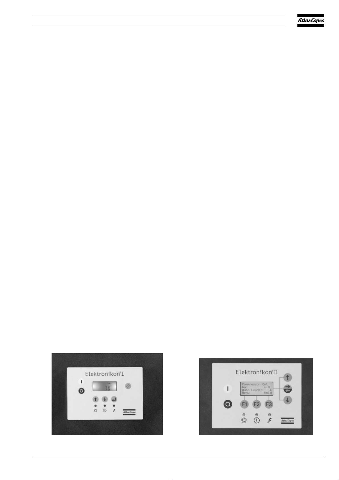
GA Pack are enclosed in a sound-insulated bodywork. The
compressors are controlled by the Atlas Copco Elektronikon
I regulator (Fig. 1.1). The electronic control module is fitted
to the door at the front side. An electric cabinet comprising the
motor starter is located behind this panel.
GA Pack FF
GA Pack FF (Full-Feature) are also controlled by the Atlas
Copco Elektronikon® I regulator (Fig. 1.1). They are
additionally provided with an air dryer integrated in the soundinsulated bodywork. The dryer removes condensate from the
compressed air by cooling the air to near freezing point and
automatically draining the condensate. See section 1.5.
GA Workplace
GA Workplace are enclosed in a sound-insulated bodywork.
The compressors are controlled by the Atlas Copco
Elektronikon® II regulator (Fig. 1.2). The electronic control
module is fitted to the door at the front side. An electric cabinet
comprising the motor starter is located behind this panel. A
condensate trap with automatic drain system is provided.
GA Workplace FF
GA Workplace FF (Full-Feature) are also controlled by the Atlas
Copco Elektronikon® II regulator (Fig. 1.2). They are
additionally provided with an air dryer integrated in the soundinsulated bodywork. The dryer removes condensate from the
compressed air by cooling the air to near freezing point and
automatically draining the condensate. See section 1.5.
1.1.2 Air flow (Figs. 1.7 and 1.8)
Air drawn through filter (1) and open inlet valve (6) into
compressor element (5) is compressed. Compressed air and
oil flow through air receiver/oil separator (15) and air cooler
®
(10) to outlet valve (21).
Minimum pressure valve (12) prevents the receiver pressure
from dropping below a minimum pressure.
1.1.3 Oil system (Figs. 1.7 and 1.8)
Air pressure forces the oil from air receiver (15) through oil
cooler (11) and filter (18) to compressor element (5) and the
lubrication points.
The system comprises a by-pass valve (20). When the oil is
warm, the valve allows all oil to pass through the cooler.
1.1.4 Cooling system (Figs. 1.7 and 1.8)
The cooling system comprises air cooler (10) and oil cooler
(11). The cooling air is generated by fan (9).
52144F
2920 1462 00
Fig. 1.1 Elektronikon I regulator
52143F
Fig. 1.2 Elektronikon II regulator
3
Instruction book
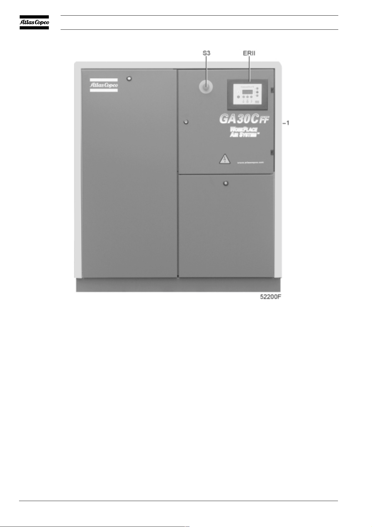
ER II Elektronikon II regulator
S3 Emergency stop button
1 Air outlet
Fig. 1.3 Front view GA30C Workplace Full-feature
1.1.5 Condensate drain system (Fig. 1.6)
All variants except for GA Pack are provided with a condensate
trap in the air outlet system. The trap is equipped with a valve
for automatic condensate draining during operation (2) and a
manually operated valve (1) for draining after stopping the
compressor.
1.2 Unloading/loading system
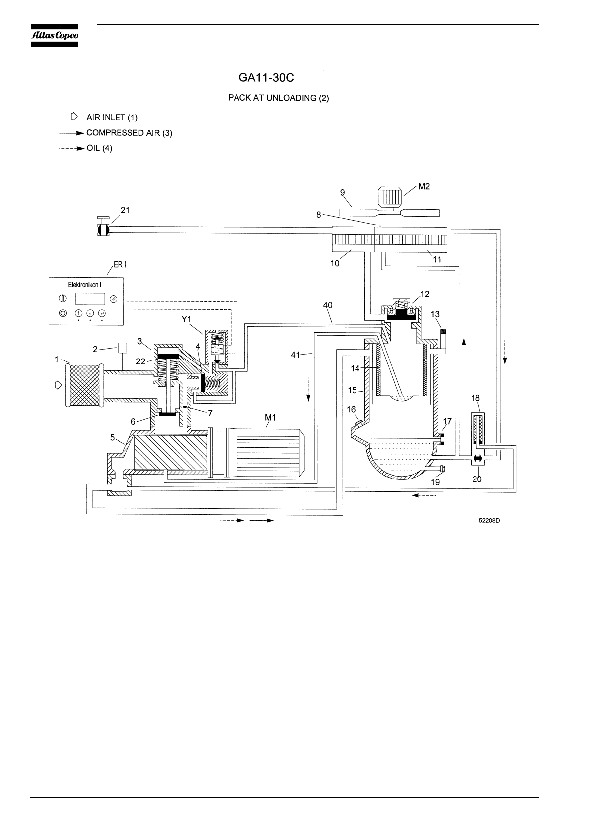
1.2.1 Unloading (Fig. 1.8)
If the air consumption is less than the air output of the
compressor, the net pressure increases. When the net pressure
reaches the unloading pressure, solenoid valve (Y1) is deenergized. The plunger of the valve returns by spring force:
4
2920 1462 00
Instruction book
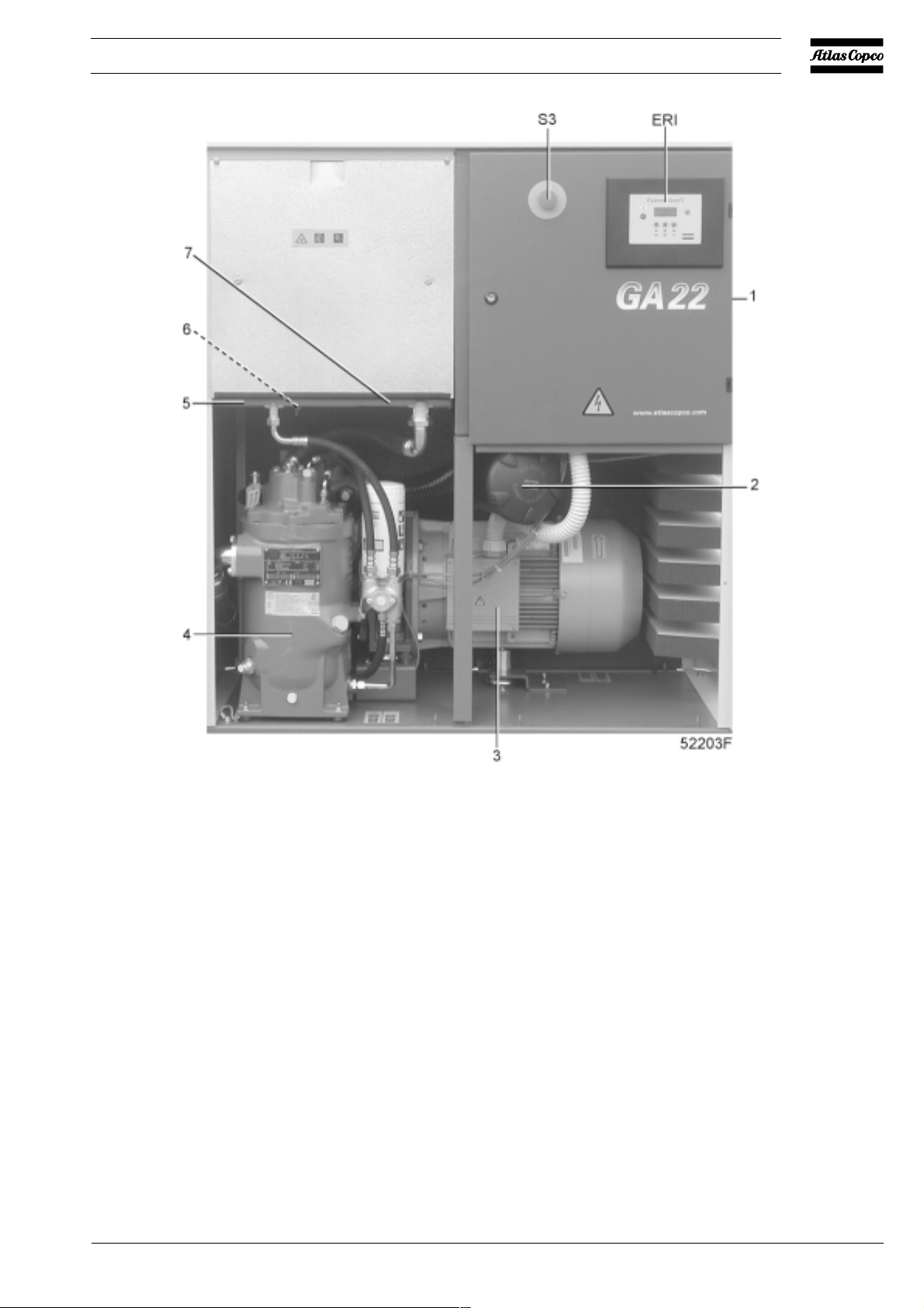
ER I Elektronikon I regulator
1 Air outlet
2 Air filter
3 Drive motor
Fig. 1.4 GA22 Pack
1. The control pressure present in the chambers of loading
plunger (22) and unloading valve (4) is vented to atmosphere
via solenoid valve (Y1).
2. Loading plunger (22) moves upwards and causes inlet valve
(6) to close the air inlet opening.
3. Unloading valve (4) is opened by receiver pressure. The
pressure from air receiver (15) is released towards unloader
(3).
Air output is stopped (0 %), the compressor runs unloaded.
4 Air receiver/oil separator
5 Oil cooler
6 Oil cooler vent plug
7 Air cooler
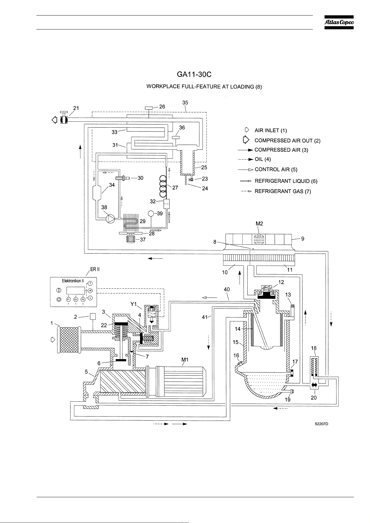
1.2.2 Loading (Fig. 1.7)
When the net pressure decreases to the loading pressure,
solenoid valve (Y1) is energized. The plunger of solenoid valve
(Y1) moves upwards against spring force:
1. Control pressure is fed from air receiver (15) via solenoid
valve (Y1) to loading plunger (22) and unloading valve (4).
2. Unloading valve (4) closes the air blow-off opening.
Loading plunger (22) moves downwards and causes inlet
valve (6) to open fully.
Air output is resumed (100 %), the compressor runs loaded.
2920 1462 00
5
Instruction book
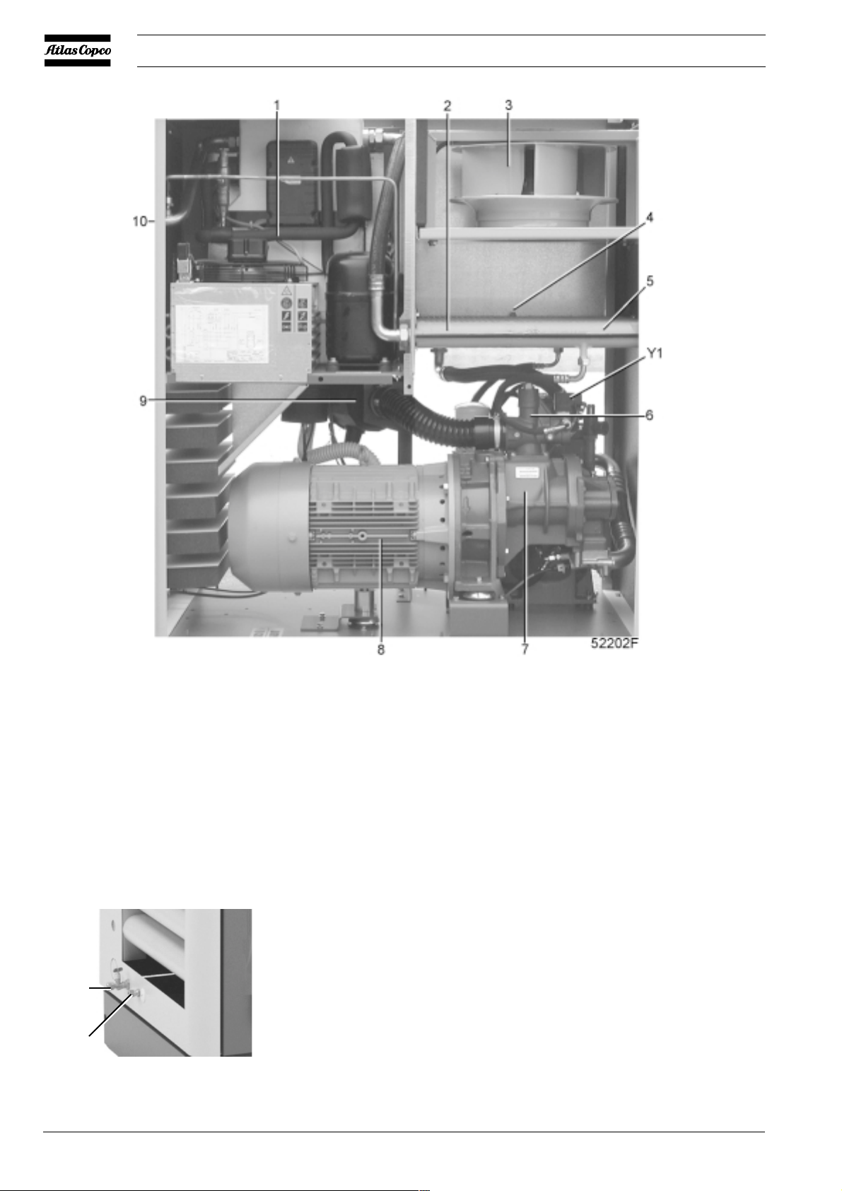
1 Dryer
2 Air cooler
3 Fan
4 Oil cooler vent plug
1
2
51 100F
5 Oil cooler
6 Unloader
7 Compressor element
8 Drive motor
Fig. 1.5 GA22 Workplace Full-Feature
1 Condensate drain valve
2 Automatic condensate drain
Fig. 1.6 Condensate outlets
9 Air filter
10 Air outlet
Y1 Loading solenoid valve
6
2920 1462 00
Instruction book
2920 1462 00
Fig. 1.7 GA Workplace Full-feature during loading
7
Instruction book
ER I Elektronikon I regulator
ER II Elektronikon II regulator
M1 Drive motor
M2 Motor, compressor cooling fan
Y1 Loading solenoid valve
1 Air filter
2 Air filter service indicator
3 Unloader
4 Unloading valve
5 Compressor element
6 Inlet valve
7 By-pass valve
8 Vent plug, oil circuit
9 Compressor cooling fan
10 Air cooler
11 Oil cooler
8
Fig. 1.8 GA Pack during unloading
12 Minimum pressure valve
13 Safety valve
14 Oil separator element
15 Air receiver
16 Oil filler plug
17 Oil level indicator
18 Oil filter
On Full-feature also:
26 Pressure sensor
27 Capillary tube
28 Condenser cooling fan
29 Refrigerant condenser
30 Hot gas by-pass valve
31 Air/refrigerant heat exchanger/
19 Oil drain plug
20 Oil cooler by-pass valve
21 Air outlet valve
22 Loading plunger
23 Manual condensate drain valve
24 Automatic condensate outlet
25 Condensate trap
40 Flexible, control air
41 Flexible, oil scavenging
32 Liquid refrigerant dryer/filter
33 Air/air heat exchanger
34 Accumulator
35 Insulating block
36 Temperature sensor
37 Motor, condenser fan
38 Refrigerant compressor
39 Fan control switch
Figs. 1.7 and 1.8 Air-oil and unloading-loading systems
evaporator
2920 1462 00

Instruction book
1.3 Elektronikon II regulator
GA Workplace and Workplace FF are provided with the
Elektronikon II regulator (Fig. 1.9).
1.3.1 Main functions
1.3.1.1 Automatic control of the compressor
The regulator maintains the net pressure between programmable
limits by automatically loading and unloading the compressor.
A number of programmable settings, e.g. the unloading and
loading pressures, the minimum stop time and the maximum
number of motor starts are taken into account.
The regulator stops the compressor whenever possible to reduce
the power consumption and restarts it automatically when the
net pressure decreases. In case the expected unloading period
is too short, the compressor is kept running to prevent tooshort standstill periods.
Warning A number of time-based automatic start/stop
commands may be programmed (consult the User
manual for Elektronikon I and II regulators). Take
into account that a start command will be executed
(if programmed and activated), even after
manually stopping the compressor.
1.3.1.2 Protecting the compressor
Shut-down
If the compressor element outlet temperature exceeds the
programmed shut-down level, the compressor will be stopped.
This will be indicated on display (3). The compressor will
also be stopped in case of overload of the drive motor and the
fan motor.
Shut-down warning
If the compressor element outlet temperature exceeds a
programmed value below the shut-down level, this will also be
indicated to warn the operator before the shut-down level is
reached.
Service warning
A number of service operations are grouped in plans (called
Service plans A, B and C). Each Service plan has a programmed
time interval. If a time interval is exceeded, a message will
appear on display (3) to warn the operator to carry out the
service actions belonging to that plan.
Warning
On Full-feature compressors, a warning message also appears
if the dewpoint temperature exceeds the warning level.
52227F
1 Stop button
2 Start button
3 Display
4 Scroll keys
5 Tabulator key
S3
1
6 Voltage on LED
7 General alarm LED
8 Automatic operation LED
9 Function keys
Fig. 1.9 Control panel, Elektronikon II
2
8
9
11
3
10
4
5
4
9
9
12
7
6
10 Pictograph, alarm
11 Pictograph, automatic operation
12 Pictograph, voltage on
S3 Emergency stop button
2920 1462 00
9

Instruction book
1.3.1.3 Automatic restart after voltage failure
For compressors leaving the factory, this function is made
inactive. If desired, the function can be activated. Consult
Atlas Copco.
Warning If activated and provided the module was in the
automatic operation mode, the compressor will
automatically restart if the supply voltage to the
module is restored within a programmed time
period.
The power recovery time (the period within which the voltage
must be restored to have an automatic restart) can be set between
10 and 600 seconds or to Infinite. If the power recovery time
is set to Infinite, the compressor will always restart after a
voltage failure, no matter how long it takes to restore the voltage.
A restart delay can also be programmed, allowing e.g. two
compressors to be restarted one after the other.
1.3.2 Control panel (Fig. 1.9)
Ref. Designation Function
1 Stop button Push button to stop the
compressor. LED (8) goes out.
The compressor will stop after
running in unloaded condition for
about 30 seconds.
Ref. Designation Function
2 Start button Push button to start the
compressor. LED (8) lights up
indicating that the regulator is
operative (in automatic operation).
The LED goes out after unloading
the compressor manually.
3 Display Indicates messages concerning the
compressor operating condition, a
service need or a fault.
4 Scroll keys Keys to scroll through the display.
5 Tabulator key Key to select the parameter
indicated by a horizontal arrow.
Only the parameters followed by
an arrow pointing to the right are
accessible for modifying.
6 Voltage on LED In dic ates t hat the voltage is
switched on.
7 General alarm LED Is alight if a warning, service
warning or shut-down warning
condition exists or if a sensor is
out of order.
7 General alarm LED Blinks in case of shut-down, if a
sensor with shut-down function is
out of order or after an emergency
stop.
10
52227F
S3
Fig. 1.9 Control panel, Workplace / Workplace FF
1
2
11
8
9
10
3
4
5
4
9
9
12
7
6
2920 1462 00

Instruction book
Ref. Designation Function
8 Automatic Indicates that the regulator is
operation LED automatically controlling the
compressor: the compressor is
loaded, unloaded, stopped and
restarted depending on the air
consumption and the limitations
programmed in the regulator.
9 Function keys Keys to control and program the
compressor. See below.
10 Pictograph Alarm
11 Pictograph Automatic operation
12 Pictograph Voltage on
S3 Emergency
stop button Push button to stop the compressor
immediately in case of emergency.
After remedying the trouble,
unlock the button by pulling it out.
2920 1462 00
See Fig. 1.11 for denomination of components
Fig. 1.10 Electric cabinet, GA Workplace / Workplace FF (typical example)
11

Instruction book
12
2920 1462 00
 Loading...