


Tensor
SAFETY INSTRUCTIONS
When using electric products, basic precautions
should be followed:
❑ THIS EQUIPMENT MUST BE EARTH GROUNDED.
❑ Always disconnect the equipment from the mains,
by pulling the plug, before opening it for installation,
service etc.
❑ Do not use this product near water.
Tensor DS Drive
Quick Guide
2
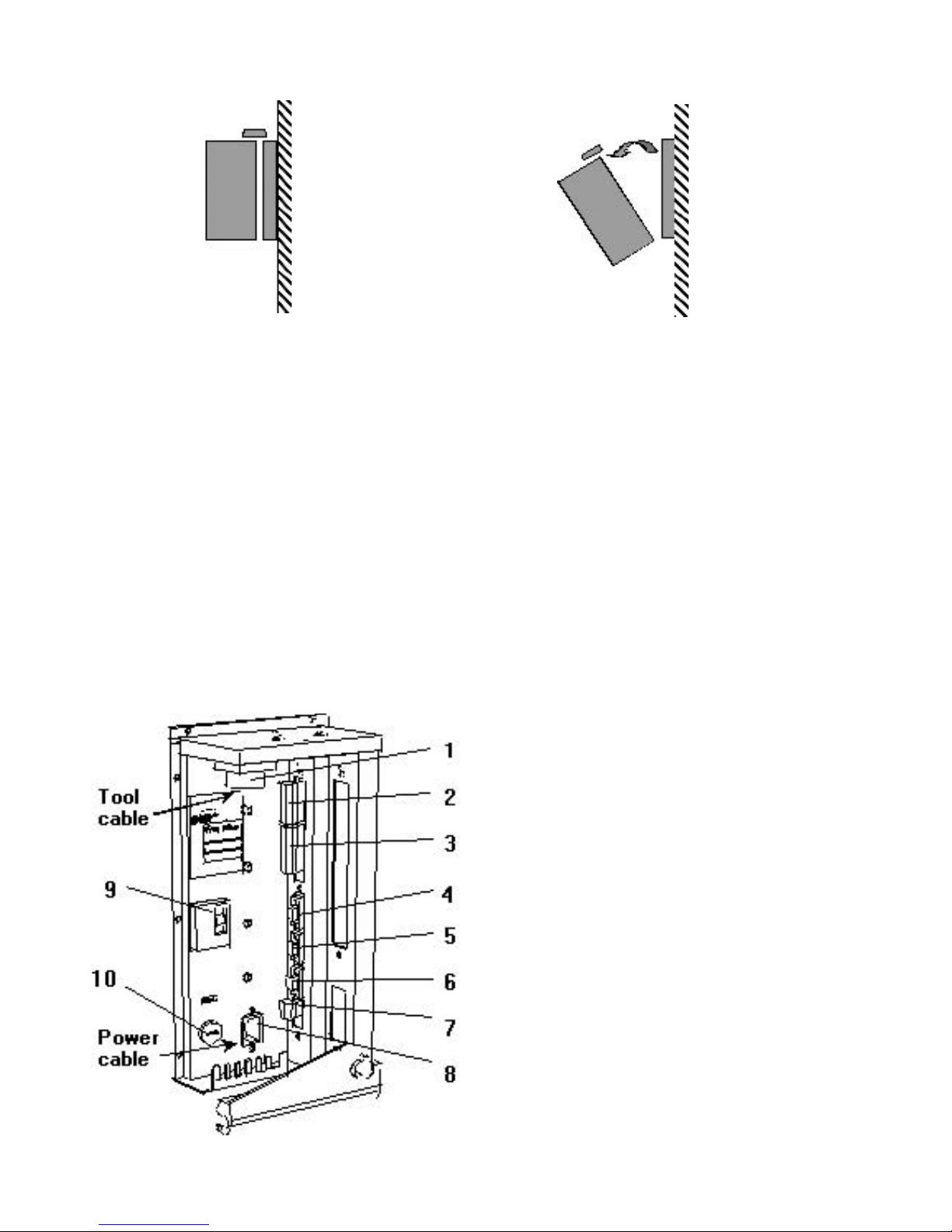
INSTALLATION HARDWARE
1. Open the lock mechanism (see figure 1)
2. Open the DS Drive by pulling it (see figure 2)
3. Connect the tool cable, power cable etc. (see figure 3)
4. Check so that the GFI is switched on
5. Close the DS Drive and lock it
6. Connect the power cable to a power supply 115/230 V
7. Turn the power on
IMPORTANT! Whenever replacing a tool, always turn the power off.
Figure 1 Figure 2
1. Tool cable connector
2. Digital inputs. Only for D312
3. Relay outputs
4. RS 232
5. I/O bus. Only activated
for D312
6. I/O bus. Only activated
for D312
7. Remote control
8. Main power connector
9. Ground fault interrupter,
GFI, 30 mA
10. Main fuse. 6.3 x 32 mm –
Slow Blow,15/20/25 A
Figure 3

15
14
13
12
11
8
7
4
1
2
3
5
6
9
10
3
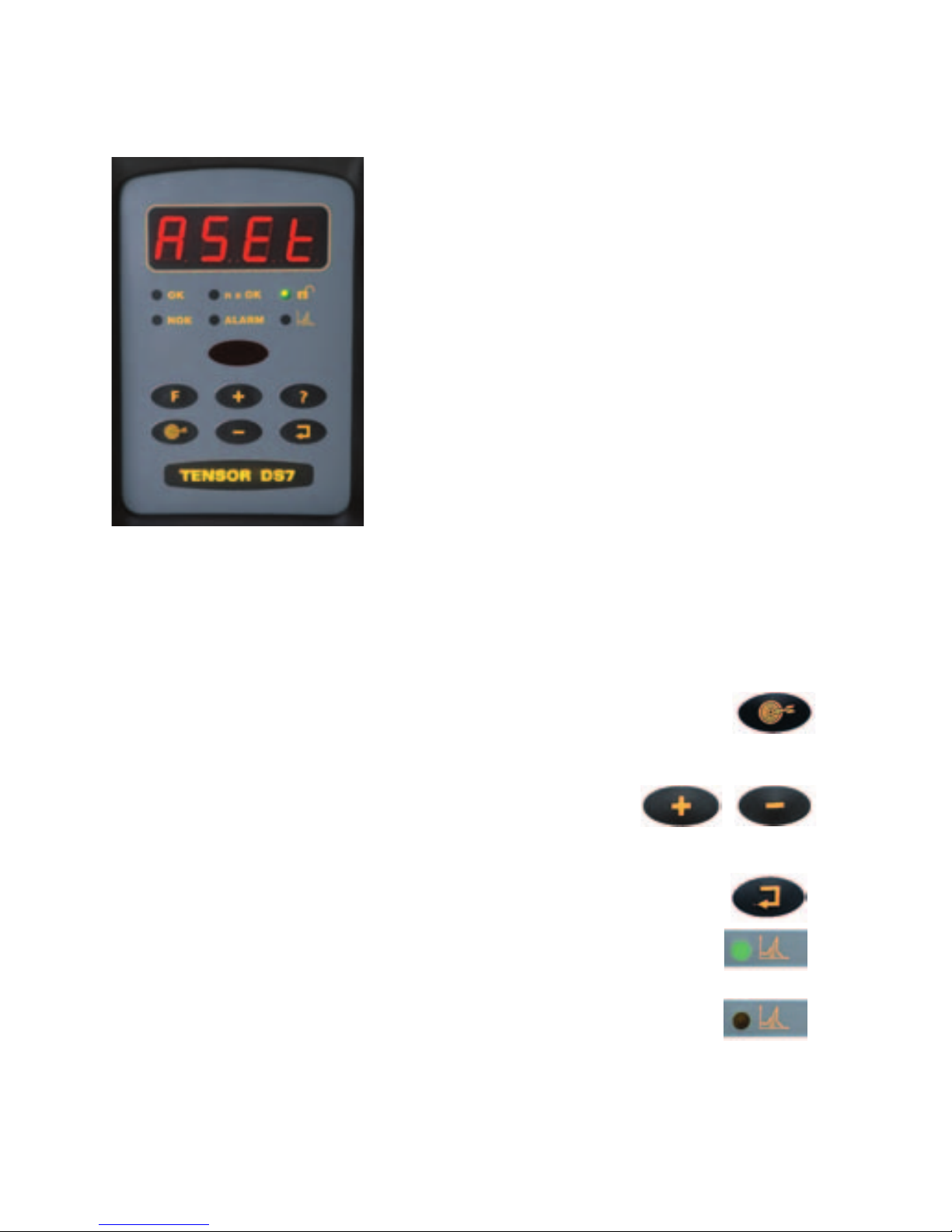
DISPLAY/KEY PAD
1. Display
2. OK LED
3. n x OK LED
4. Lock LED
5. NOK LED
6. Alarm LED
7. Graph LED
8. IRDA
9. Function button
10. AutoSet button
11. Plus button (+)
12. Question mark
button
13. Enter key button
14. Minus button (-)
15. Power
OK LED
Lights up after each tightening with
correct torque.
NOK LED
– Lights up af ter each tightening reaching
first target but not correct torque.
Question Mark
– By pushing this button you can see:
❑ Drive program software version.
❑ Drive version (D302-Basic functionality,
D312-Advanced functionality).
❑ Drive size (DS4, DS7, DS9).
For further information check the DS Drive Manual.
–
4
1. Press the AUTOSET button once and ASEt/F1
appears on the display.
2. Choose final torque target by pressing
+/- buttons.
3. Press the ENTER button once to activate the
AutoSet function.
The Graph LED, lights up.
4. Resume tightening (5-8 times) until the Graph LED
disappear.
Optimum performance has been found and the system is ready
for production.
KEY PAD FUNCTIONS
AutoSet Programming:
The AutoSet Programming
feature allows the DS Drive to
recognise a joint’s stiffness and
adjust the tool for maximum
performance for that particular
joint accordingly.
/
5
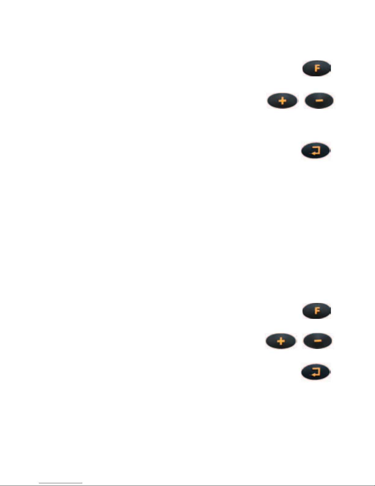
Fine – Tuning Final Target
This enables personnel to fine the final target.
1. Press the FUNCTION button once and Ft/F2
appears on the display.
2. Adjust final torque target by pressing
the +/- buttons.
(The torque can be adjusted a maximum of +15%
or –5% from the original final target).
3. Press the ENTER button and the display starts
to flash.
4. When a new final target has been found within above limits,
the DS Drive is ready to run that program.
Torque Tuning
This is used when a tool is controlled against an external torque
reference. If the torque value on the DS differs from the
traceable value, a Torque Tuning should be performed.
1. Perform a number of tightenings with the external torque
transducer connected, preferably 20 tightenings or more in
order to achieve a good mean value. Calculate the mean value
from the tightenings.
2. Press the FUNCTION button twice and tunE/F3
appears on the display.
3. Press the +/- button until you have the
external mean value on the display.
4. Press the ENTER button and the display starts
to flash.
5. Perform another set of tightenings to control your torque.
6. If the torque is OK you are ready to run. If not, do the
complete procedure over again.
/
/
 Loading...