


TABLE OF CONTENTS |
|
Section 1 GENERAL INFORMATION .......................... |
1 |
1-1 Introduction |
1 |
General Specifications |
2 |
Receiver Specifications ............................ |
3 |
Transmitter Specifications |
3 |
Model 220-CS Power Supply Console Specifications ......... |
4 |
Model 200-PS Portable AC Supply ..................... |
4 |
Rechargeable Battery pack |
5 |
Section 2 INSTALLATION .................................. |
6 |
2-1 Introduction |
6 |
2-2 General Information .............................. |
6 |
2-22 Mobile Installations ............................... |
9 |
2-28 Fixed Station Installations .......................... |
13 |
2-29 Antennas |
13 |
2-33 Fixed Station Antennas |
14 |
Section 3 OPERATION ...................................... |
15 |
3-1 Introduction ................................... |
15 |
3-2 Controls ...................................... |
15 |
3-3 Power Supply On/Off, Mobile Operation ................. |
15 |
3-4 Power Supply On/Off, 220-CS/200-PS .................. |
15 |
3-5 Function Switch |
15 |
3-6 A. F.Gain ..................................... |
15 |
3-7 R. F.Gain ..................................... |
15 |
3-8 Band Selector and Tuning Dial, Model 210X .............. |
15 |
3-9 Band Selector and Tuning Dial, Model 215X |
17 |
3-10 Dial Set ....................................... |
17 |
3-11 Carrier Balance |
17 |
3-12 S-Meter Zero ................................... |
17 |
3-13 Crystal Calibrator ................................ |
17 |
3-14 Proper tuning od Single Sideband Signals |
17 |
3-15 Voice Transmission ............................... |
17 |
3-16 Modulation Level |
18 |
3-17 ALC......................................... |
18 |
3-18 CW Transmission |
18 |
3-19 Heat Sink ..................................... |
18 |
Section 4 CIRCUIT THEORY ................................ |
20 |
4-1 Introduction |
20 |
4-2 Receiver Input Circuit |
20 |
4-3 Sensitivity ..................................... |
20 |
4-4 Selectivity ..................................... |
20 |
4-5 Oscillator Switching .............................. |
20 |
4-6 Transmitter Broadband Circuitry |
24 |
4-7 Receiver Broadband Circuitry |
24 |
4-8 Alignment and Troubleshooting ...................... |
24 |
4-9 Voltage Charts .................................. |
24 |
4-10 Signal Frequency Ranges and Local Oscillator Frequencies ..... |
25 |
4-11 PC-100C - First Mixer/First I.F. Amplifier ............... |
26 |
4-12 PC-200C — Second I.F. Amplifier, Second Mixer, Mic. Amp. |
|
S-Meter Amp. .................................. |
28 |
4-13 PC-300D - Receiver Audio, Oscillator Switch ............. |
30 |
4-14 PC-500D/520A - Pre-Amplifier, Driver, Power Amplifier, |
|
SWR Protect ................................... |
32 |
4-15 PC-400C VFO Board and Tuning Circuits ............... |
34 |
4-16 PC-600 Carrier Oscillator, Buffer Amplifier ............. |
36 |
4-17 PC-800C/1200 Receiver Input Tuning ................. |
38 |
4-18 PC-820 100 kHz Crystal Calibrator ................... |
41 |

|
4-19 PC-900C Transmitter Input Tuning .....…………………………………………............ 42 |
|
|
4-20 PC-1010/1020 Low Pass Filters ...................…………………………………………… 44 |
|
|
4-21 PC-1100A SWR Bridge, Antenna Relay ..............……………………………………… 46 |
|
Section 5 ACCESSORIES .................................... |
………………………………………………………47 |
|
|
5-1 Model PC-120 Noise Blanker ....................... |
……………………………………………47 |
|
5-2 Model l0x Crystal Oscillator ....................... |
……………………………………………...49 |
|
5-4 Model VX-5 VOX .............................. |
……………………………………………………52 |
|
5-5 Model DD-6 Digital Dial .......................... |
……………………………………………….52 |
|
|
|
|
LIST OF ILLUSTRATIONS |
|
Figure |
|
|
1-1 |
Atlas Model 21 Ox Illustrated with Optional 220-CS AC Console |
......... 1 |
2-1 |
Remote CW Transmit Switch for Atlas Transceivers |
......... 8 |
2-2 |
Linear Amplifier connections for Atlas Transceivers |
......... 10 |
2-3 |
Deluxe Plug-In Mobile Mounting Kit Installation |
......... 11 |
2-4 |
Mobile Bracket Kit Installation ...................... |
......... 11 |
2-5 |
D.C. Power Connections .......................... |
......... 12 |
2-6 |
Model 220-CS/200-PS Schematic Diagram ............... |
......... 14 |
3-1 |
Front Panel of ATLAS 210x ........................ |
......... 16 |
3-2 |
Rear Panel of ATLAS 210x/215x .................... |
......... 16 |
4-1 |
ATLAS 210x/215x Modular Design and Plug-in P.C. Boards . . . |
......... 21 |
4-2 |
ATLAS 210x/215x Block Diagram ................... |
......... 22 |
4-3 |
Crystal Ladder Filter Selectivity Characteristics ........... |
......... 23 |
4-4 |
PC-100C Schematic Diagram ........................ |
......... 27 |
4-5 |
PC-200C Schematic Diagram ........................ |
......... 29 |
4-6 |
PC-300C Schematic Diagram ........................ |
......... 31 |
4-7 |
PC-500D/520A Schematic Diagram ................... |
......... 33 |
4-8A |
Model 210x PC-400C Schematic Diagram ............... |
......... 35 |
4-8B |
Model 215x PC-400C Schematic (tuning section only) ....... |
......... 35 |
4-9 |
PC-600 Schematic Diagram ......................... |
......... 37 |
4-10A |
Model 210x PC-800C/1200 Scliematic Diagram ........... |
......... 39 |
4-10B |
Model 215x PC-8000/1200 Schematic Diagram ........... |
......... 40 |
4-11 |
PC-820 Crystal Calibrator Schematic Diagram |
......... 41 |
4-12 |
PC-9000 Transmitter Input Tuning Schematic Diagram ...... |
......... 43 |
4-13 |
PC-1010/1020 low Pass Filter Schematic Diagram ......... |
......... 45 |
4-14 |
PC-1100A SWR Bridge, Antenna Relay Scliematic Diagram . . . |
......... 46 |
5-1 |
PC-120 Noise Blanker Schematic Diagram ............... |
......... 48 |
5-2 |
Model l0x Crystal Oscillator ........................ |
......... 49 |
5-3 |
Model 10X Crystal Oscillator Schematic Diagram |
......... 50 |
5-4 |
Model MT-1 Transformer installation |
......... 51 |
5-5 |
Model DD-6 Digital Dial ........................... |
......... 52 |
5-6 |
Model 210x/215x Chassis Wiring ..................... |
inside back cover |
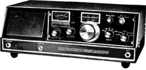
Figure 1-1. Atlas Model 210x Illustrated with Optional 220-CS AC Console
SECTION 1 GENERAL
INFORMATION
1-1. INTRODUCTION
The Atlas 210x Transceiver is designed for single sideband and CW communications in the 10, 15, 20, 40, and 80 meter amateur radio bands. The Atlas 215x covers 15, 20, 40, 80, and 160 meters. They employ all solid state circuitry, with modular construction. The conservative 200 watt power input rating will provide world wide communications from fixed, portable or mobile installations.
Atlas Radio, Inc., is licensed by Southcom International, Inc. of Escondido, California, manufacturers of military and commercial radio equipment. With this agreement. Atlas Radio is able to bring the most advanced state-of-the- art circuit designs to the amateur radio market. Les Earnshaw, founder and Director of R&D at Southcom International, is considered to be one of the foremost solid state engineers in the world, effectively proved by the rapid growth of Southcom International in the military and commercial radio markets of the United States, as well as many other countries.
The high performance and reliability of the Atlas transceiver is enhanced by the finest craftsmanship, and a most thorough quality control program. Our staff is made up of highly skilled assembly workers, technicians, and engineers, many of whom are active radio hams. Our service department, if and when needed, is dedicated to making every Atlas owner a satisfied customer. Speaking for all the gang at Atlas Radio, we wish you many hours of operating pleasure with your Atlas transceiver.
73 Herb Johnson W6QKI President
GENERAL SPECIFICATIONS
BAND COVERAGE:
ATLAS 21 Ox: Covers 80, 40, 20, 15, and 10 meter bands, with internal VFO ranges as follows:
35004000kHz
70007500kHz
14000-14500 kHz
21000-21500 kHz
28400 - 29400 kHz
NOTE: The 10 meter band on the 210x may be easily owner adjusted to cover any 1000 kHz portion of the band.
ATLAS 215x: Covers 160, 80, 40, 20, and 15 meter bands, with internal VFO ranges as follows:
1800 |
2100kHz |
3500 |
4000kHz |
7000 |
7500kHz |
14000 |
14500kHz |
21000 |
21500 kHz |
FREQUENCY CONTROL;
Highly stable VFO common to both receive and transmit modes.
13800 |
14900kHz |
20600 |
21600 kHz |
Note: The Model l0x will not operate on the 28.0 MHz band.
CIRCUIT DESIGN:
All solid state, 4 IC's, 18 transistors, 31 diodes. Single conversion, 5520 kHz I.F.
MODULAR CONSTRUCTION:
Includes plug-in circuit boards for ease of maintenance.
PLUG-IN DESIGN:
Transceiver plugs into the Deluxe Mobile Mounting Bracket, or into the optional 220-CS power supply console, making transfer or removal a simple operation. All connectors are standard: SO-239 antenna jack, 1/4 in. phone jacks for Mic., CW key, external speaker or headphones, and linear amplified control.
FREQUENCY READOUT:
Dial scale calibrated in 5 kHz increments on all bands except 10 meters, where increments are 10 kHz. Tuning knob skirt provides 1 kHz increments on all bands except 10 meters, where increments are 2 kHz.
EXTERNAL FREQUENCY
CONTROL:
Rear socket provides for plug-in of external VFO or crystal oscillator accessory for separate control of transmit and receive frequencies, or for network and MARS operation.
EXTENDED FREQUENCY RANGE WITH CRYSTAL OSCILLATOR:
When the model lOx external crystal oscillator accessory is used, frequency ranges are as listed in the following charts:
1800 - 3000 kHz (Model 215x only)
30005200kHz
5800 - 10000 kHz
POWER SUPPLY REQUIREMENTS
Operates directly from a 12 to 14 volt D.C. source with negative ground (standard automotive system). Current drain is 300 to 500 ma. in receive mode, 16 amps. peak in transmit mode. Atlas model 220-CS power supply console and the model 200-PS portable supply are available for AC operation.
FRONT CONTROLS:
Tuning Dial, Dial Set, Function Switch, Band Switch, A.F. Gain, R.F. Gain, Mic Gain, Sideband Selector, Calibrator On-Off, Dial Light Dimmer, ALC Control.
FINISH:
Black vinyl covered aluminum cabinet and bottom cover, anodized aluminum panel.
WEIGHT:
6 Ibs. 14 oz. (3.1 Kg) net, 8 Ibs. 6 oz. (3.8 Kg) shipping weight.
DIMENSIONS:
9'/2 in. (24.1 cm) wide, 3'/2 in (8.9 cm) high, 9Vi in. (24.1 cm) deep overall.
2
RECEIVER SPECIFICATIONS
CIRCUIT DESIGN: Front end design provides exceptional immunity to overload and cross modulation, matching or out performing the best vacuum tube designs. Signals are converted directly to the 5520 kHz I.F. without preamplification. Converter and product detector are double balanced diode rings. IC's are employed in I.F. and AF stages.
SENSITIVITY: Requires less than 0.4 microvolts for a 10 db signal-plus-noise to noise ratio on 160, 80, 40, and 20 meter bands; 0.4 microvolts on 15 meters; and 0.6 microvolts on 10 meters. SELECTIVITY: Crystal Ladder Filter, 8 poles. Bandwidth: 2.7 kHz @ 6 db, 4.3 kHz @60db,9.2kHz@ 120 db!! Ultimate rejection more than 130db!! Shape Factor 1.6.
IMAGE REJECTION: More than 60 db.
INTERNAL SPURIOUS: Less than equivalent 1 microvolt signal. AGC CHACTERISTICS: Audio output constant within 4 db with signal
variation from 5 microvolts to more than 3 volts.
OVERALL GAIN: Requires less than 1 microvolt signal for 0.5 watts audio output. (CW carrier, 1000 Hertz heterdyne).
AUDIO FIDELITY: 300 to 3000 Hertz, plus or minus 3 db. INTERNAL SPEAKER: 3 in., 3.2 ohm,
.68 oz. magnet. Rear jack permits plug in of external speaker or headphones. Headphones of 500 to 600 ohms are recommended. Headphones of a higher impedance may be used, but will require a higher A.F. Gain setting. Lower impedance headphones will require a lower A.F. Gain setting. When transceiver is plugged into the AC power supply console, internal speaker is disconnected automatically, and front facing speaker on console becomes operative.
METER: Reads "S" units from 1 to 9, plus lOtoSOdb. CALIBRATOR: Provides 100 kHz check points for accurate dial setting.
TRANSMITTER SPECIFICATIONS
CIRCUIT DESIGN : Broadband design eliminates transmitter tuning. Single conversion from I.F. to output frequency produces minimum spurious and mixing products. 2 section low-pass filters on each band provide harmonic suppression equal to commercial standards. Includes ALC and infinite SWR protection.
FREQUENCY CONTROL: Internal VFO automatically transmits on exactly the same frequency that is being received. Rear socket provides for plugin of external VFO or crystal oscillator accessory for separate control of transmit and receive frequencies, or for network and MARS operation.
POWER RATING: 200 watts P.E.P. input, and CW input, (with 50 ohm resistive load and 13.6 volt D.C. supply) on 160,80,40,20,and 15 meter bands; 120W on 10 meter band. Power output: 80 minimum P.E.P. and CW on 160, 80, 40, 20, and 15 meter bands; 50 watts minimum on 10 meter band.
RTTY /SSTV POWER RATING:
Approximately 90 watts P.E.P input (dependent directly on ventilation of heat sink).
EMISSION : SSB: Lower sideband on 40, 80, and 160 meters. Upper sideband on 20, 15, and 10 meters with Sideband Selector switch in NORM position. Opposite with switch in OPP position. CW: offset frequency.
UNWANTED SIDEBAND: More than 60 db down at 1000 Hertz AF input.
CARRIER SUPPRESSION: More than
50 db down.
THIRD ORDER DISTORTION:
Approximately 30 db below peak power.
HARMONIC OUTPUT: More than 35 db below peak power.
SUPRIOUS AND IMAGE OUTPUT:
More than 40 db below peak power.
CW KEYING: Manual send-receive.Semi-break-in with CW accessory installed in AC power supply console.
TRANSMIT CONTROL: Press to talk with Mic. button, or manual transmit with Function Switch on front panel. Automatic voice control when VOX accessory is installed in AC power supply console.
MICROPHONE: Dynamic or crystal.
Plug requirement: standard % in. diam. 3 circuit phone plug.
AUDIO FIDELITY: 300 to 3000 Hertz, plus or minus 3 db.
METER: Reads power amplifier collector current, 0- 16 amperes.
LINEAR AMPLIFIER CONTROL:
Rear jack provides for keying of linear, and ALC control from linear.
MODEL 220-CS POWER SUPPLY CONSOLE SPECIFICATIONS
INPUT VOLTAGE: 110 or 220 volts AC, 50-60 Hz.
INPUT POWER: 10 watts average, receive. 250 watts transmit peak.
OUTPUT: Low current line: 13.6 volts regulated, Vi amp. High current line: 13 volts at 16 amps.
SPEAKER: 3x5 in. oval, 1.1 oz. magnet, 3.2 ohm voice coil.
FINISH: Textured Vinyl bonded to aluminum, durable and scratch resistant.
PLUG-IN DESIGN: Transceiver plugs directly into power supply console, automatically makes connections for antenna and front facing speaker. Mic. jack and headphone jack are brought out to front panel.
ACCESSORIES: Space under transceiver permits addition of VOX unit. Space in rear permits addition of semi-break-in CW.
DIMENSIONS: 15-1/2 in. (39.4 cm) wide. 5-5/8 in. (14.3 cm) high. 9-1/2 in. (24.1 cm) deep.
WEIGHT: 17 Ibs. (7.7 Kg) less transceiver. 20 Ibs. (9.1 Kg) shipping weight.
MODEL 200-PS PORTABLE AC SUPPLY
INPUT VOLTAGE: 110 or 220 volts
AC, 50-60 Hertz.
INPUT POWER: 10 watts average, receive. 250 watts transmit peak.
OUTPUT: Low current line: 13.6 volts regulated, Vi amp. High current line: 12.5 volts at 16 amps.
INCLUDES: On-Off switch, Fuses, AC cord, and D.C. Cable with connector for transceiver.
DIMENSION: 5-1/4 in. (13.3 cm) wide, 3-1/2 in. (8.9 cm) high, 6-1/2 in. (16.5 cm) deep.
WEIGHT: 7 Ibs. 4 oz. (3.3 Kg) less transceiver. 10 Ibs. (4.5 Kg) shipping weight.
RECHARGEABLE BATTERY PACK
Globe Battery Division, Globe-Union Inc., P.O. Box 591, Milwaukee, Wis. 53201, manufactures a "GEL-CELL" rechargeable Battery Pack, Model GC1400 which will operate the Atlas transceivers for a number of hours, with operating time determined by receive-transmit ratio, and modulation level. The battery has an Amphere-Hour rating of 7.5 A.H. It comes in a simulated leather case with shoulder strap, and includes an AC charger.
Your Atlas dealer may handle Globe products. Also, it is anticipated that Atlas Radio may have the GC1400 pack available for Atlas dealers. Otherwise, you may contact Globe directly for reference to a Globe dealer.
SECTION 2
INSTALLATION
2-1. INTRODUCTION This section provides instructions for mobile, portable, or fixed station installations of the
Atlas 210x/215x transceivers.
22. GENERAL INFORMATION
2-3. D.C. POWER. The Atlas transceiver is designed to operate on a power source of 12-14 volts D.C. Power can be delivered to the transceiver via the Deluxe Mounting Kit (DMK), D.C. Cable (DCC), Cigarette Lighter Cable (CLC), Portable Battery Pack, 220-CS AC Console, or 200-PS Portable AC Supply.
2-4. AUTOMOTIVE D.C. ELECTRICAL SYSTEMS. The D.C. electrical systems in automobiles may at times generate high voltage transients (spikes of voltage superimposed on the 12-14 volt D.C. system). These transients may be caused by faulty brushes in the starter motor, alternator or generator, or loose wiring, and can represent a possible hazard to the semiconductors in the transceiver. For this reason, we strongly urge that you read the following notes and follow them carefully.
(a)Clean the battery terminals and clamps, and tighten the clamps securely.
(b)Tighten battery cable terminals where they attach to the engine.
(c)Inspect battery cables and terminals for corrosion or wear. Replace them if they look questionable.
(d)Check battery condition frequently, especially when it approaches its warranty age limit. Use a protective silicone grease on the terminals to inhibit corrosion.
(e)Check the alternator and regulator connections for tightness. Check primary ignition wiring, horn wiring, lights, etc.
(f)Measure the charging voltage from the alternator with the engine running at about twice idling speed. Voltage at the battery terminals should measure 13 volts minimum, 14.5 volts maximum. Consult your auto-electric service shop if correction is required.
2-5. DELUXE MOUNTING KIT (DMK). The Deluxe Mobile Mounting Kit is a plug-in unit designed for easy removal of the Atlas transceivers. All D.C. power connections are made to the DMK and all necessary hook-up cables, including the D.C. battery cable with polarity protection, circuit breaker, and hardware, are part of the kit.
2-6. D.C. CABLE (DCC). The D.C. Cable (DCC) is designed with built-in polarity protection and overload protection. This cable is available from Atlas dealers and can be used with the Mobile Bracket Kit (MBK) or a portable battery pack.
27. CIGARETTE LIGHTER CABLE (CLC). The Cigarette Lighter Cable is designed for use in those instances when D.C. power is required, and the transceiver has not been installed in the automobile using the DMK or MBK kits. The cable has a special cigarette lighter plug on one end, and a transceiver power plug on the other. Polarity and overload protection is included with the cable.
2-8. PORTABLE BATTERY PACK. The 7.5 ampere hour Portable Battery Pack provides 12 volts D.C. power via portable rechargeable batteries. Connections from the battery pack to the transceiver are made with the battery pack cable. All necessary plugs arc provided.
2-9. 220-CS AC CONSOLE. The 220-CS AC Consoles are available through Atlas dealers, and provide all the D.C. power required for the Atlas transceivers The 220-CS operates from either 110 volts AC or 220 volts AC, selected by changing fuses. A Microphone jack, Headphone jack, and antenna connector are also provided on the console.
2-10. 200-PS PORTABLE AC SUPPLY. The model 200-PS AC Supply is designed for portable and utility service where the weight and size of the deluxe AC console is not desired. It's compact size and lightweight make it ideal for the traveler, and yet it will do a completely adequate job in full time duty at the home station. It has a slightly smaller power transformer than the AC console, which reduces D.C. input power about 5 percent, but peak power with voice modulation is the same as with the larger transformer. Also, the 200-PS does not contain a speaker, so the one built into the transceiver is used. The 200-PS operates on either 110 volts AC or 220 volts AC, selected by changing fuses.
It is anticipated that a plastic or simulated leather carrying case will be available from Atlas Radio for the 200-PS supply as well as for the transceiver in the near future.
2-11. TRANSMISSION LINE IMPEDANCE MATCHING. Proper impedance match between the coaxial feedline and the antenna system is considerably more important with the broadbanded solid state amplifier than with tube type transmitters, which generally have a Pi-type matching network. The SWR should be as low as it can be in order to permit full power operation. As SWR increases, power output from the Atlas transceiver decreases approximately as indicated in the following table.
|
|
TABLE 2-1. SWR VERSUS OUTPUT |
||
|
|
|
|
|
SWR |
APPROXIMATE |
|
NOTE |
|
|
OUTPUT |
|
|
|
|
|
|
|
|
1.0 |
100 watts |
|
High SWR will not damage the |
|
1.1 |
98 watts |
|
Atlas transceiver. You may feel |
|
1.2 |
95 watts |
|
free to operate regardless of the |
|
1.3 |
90 watts |
|
SWR. Only power input and |
|
1.5 |
80 watts |
|
output will suffer. Reflected |
|
2.0 |
50 watts |
|
voltage will not cause damage. |
|
3.0 |
20 watts |
|
|
|
|
|
|
|
|
2-12. AMMETER READINGS. The ammeter on the Atlas transceiver provides an excellent indicator of impedance match. In CW transmit mode, the Mic. Gain control becomes the Carrier Insertion control. With a close match you will be able to run the ammeter up to 12 amps or more (with supply voltage of 13.6 VDC or 117/230 VAC).
2-13. INFINITE SWR PROTECTION. The Atlas transceiver has a built-in reflecto-meter which automatically reduces transmitter drive as SWR increases. This makes the power transistors nearly immune to damage from mismatched loads.
2-14. SWR MEASUREMENTS. A bridge for measuring Standing Wave Ratio (SWR) is very useful and strongly recommended for checking impedance match. Use the following procedures.
(a)Switch the bridge to "Forward" or "Sensitivity position.
(b)Set the sensitivity control on the bridge to maximum clockwise position.
(c)Set Mic. Gain on Atlas transceiver to minimum.
(d)Set the transceiver Function Switch to CW mode.
(e)Advance Mic. Gain until meter on bridge reads just full scale. (Mic. Gain is Carrier Insertion control in CW mode).
(f)
Switch bridge to "SWR" or "Reflected" position for the SWR reading.
(g)Tune the transceiver up and down in frequency until you locate minimum SWR. This will indicate the
resonant frequency of the antenna, and also the SWR at that frequency.
(h)
Switch the transceiver back to REC. mode. See Caution note, next page.
CAUTION
OPERATE THE TRANSCEIVER IN CW MODE FOR ONLY SHORT
PERIODS 0V TIME, JUST LONG ENOUGH TO MAKE THE SWR
MEASUREMENT. CHECK HEAT SINK TEMPERATURE DURING
SWR TESTS, AND IE IT IS GETTING QUITE WARM TO THE
TOUCH, LET THE RIG COOL FOR A FEW MINUTES BEFORE
CONTINUING.
2-15. MICROPHONE CONNECTIONS. The microphone may be either a dynamic or crystal type. A low impedance Mic. will work, but will require higher setting of the Mic. Gain control, and may require closer speaking. If a dynamic Mic. is selected, it should preferably be the high impedance type. The choice of microphones is important for good speech quality, and deserves careful consideration. Select a high quality Mic. with smooth response from 300 to 3000 Hertz or more. An excellent choice is the Shure 404C hand Mic. The plug required for the Mic. connector is a standard 1/4 inch diameter, 3 conductor type. The tip connection is the keying circuit for press-to-talk, the ring connection is for the shielded Mic. lead, and the sleeve or barrel is the common ground terminal.
216. VOICE OPERATED TRANSMISSION (VOX). Most press-to talk microphones arc short circuited when the button is not pressed, if the VOX accessory is installed in the AC console, this feature must be disabled. Refer to instructions that come with the Mic. Open the case and locate the switch contacts that short the Mic circuit when the button is not pressed, either disconnect the leads, or bend the contact so they do not make.
2-17. CW KEY. A jack on back of the transceiver is provided for insertion of a standard 1/4 inch diameter 2 conductor phone plug. Connect the CW key to this plug with a 2 conductor cable. The sleeve connection goes to chassis ground. Keying potential is less than 10 volts, positive, and draws less than 5 milliampères. Any of the electronic keyers presently on the market will operate satisfactorily.
2-18. REMOTE CW TRANSMIT SWITCH FOR ATLAS TRANSCEIVERS.
The Atlas transceivers have a function switch which provides for switching into the CW Transmit mode. However, it requires switching from the RLC. to TRANS., and then to the CW position. This procedure is rather awkward, and the circuit shown below (Figure 2-1) provides a more convenient system.
Figure 2-1. Remote CW Transmit Switch for ATLAS Transceivers
8
The remote switch can be a double pole, single throw toggle switch, and may be installed on a bracket or in a small utility box along with the two diodes. Other parts required are two phone plugs, a 9 pin Noval plug, a 4 conductor cable, and a single insulated conductor.
The remote switch unit may be secured near the CW key, or possibly attached to one side of the key base, permitting quick and easy switching to the CW Transmit mode.
Operation of the circuit is as follows:
When the switch is closed, the single conductor wire coming from the MicJack is grounded through the 1N4005 diode, and the switch to pin 4 or the EXT. OSC. socket. This causes the relays in the transceiver to close, placing the transceiver in transmit mode. At the same time, the lead coming from pin 9 is grounded through the 1N4148 diode, thus disabling the Mic. Amp., and preventing voice modulation of the CW signal.
The other circuit of the 2 pole switch connects the +13 volt line from pin 8 to the +CW lead going to pin 1 of the EXT. OSC. socket. This causes the carrier oscillator frequency (NORM. SB only) to move about 800 cycles up into the filter passband, thus providing automatic off-set frequency during CW transmission.
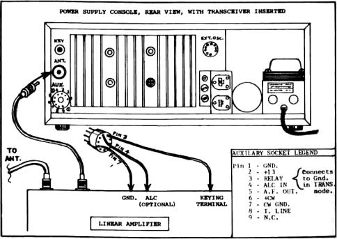
2-19. EXTERNAL OSCILLATOR SOCKET. This socket is a 9 pin Noval installed on the back of the transceiver, and is for plug in of the Atlas Model lOx Crystal Oscillator accessory, Model 206 External VFO, or the Model DD-6B-C Digital Dials. Jumper wires are factory installed on this socket, and must be removed if any of these accessories are to be used. 2-20. AUXILIARY SOCKET. This socket is also a 9 pin Noval, and is for control of a Linear Amplifier or VX-5 or VX-5M CW Semi-breakin.
2-21. LINEAR AMPLIFIER CONNECTIONS. Figure 2-2 illustrates how to connect a linear amplifier to the Atlas transceivers. ALC output from the linear may be connected to Pin 4 on the AUX. socket plug. The ALC control voltage from the linear MUST be positive going. Most linears with an ALC output circuit are negative going. If this is the case with your linear, and you wish to utilize ALC control from the linear, it will be necessary that you modify the linear ALC circuit. This will usually consist of reversing one or two diodes in order to generate a positive voltage control instead of negative.
In view of this requirement, you may choose to use the ALC system of the Atlas transceiver alone. Most linears will operate to the full legal power limit with little or no distortion.
2-22. MOBILE INSTALLATIONS
2-23. DELUXE PLUG-IN MOBILE MOUNTING KIT.
This kit includes:
(a) 6'/2 foot D.C. power cable; (b) 25 Amp. Circuit Breaker; (c) Black anodized aluminum plug-in housing; (d) Two 9-inch and two 12-inch cadmium plated steel mounting bars;
(e) 3 inch wide rear bracket; (f) Package of screws and terminal lugs. Refer to Figure 2-3 for typical transmission hump and under dash mounting arrangements.
1.The rear bracket(s)) should be angled as straight back as possible in order to give good support for pushing and pulling the transceiver in and out of the mount.
2.The mounting brackets must be cut and bent to suit the installation, each being unique. Try different positioning and select the one for best ease of operation, and least interference with automobile controls. Then carefully measure each bracket for length and angle of bend on its toot. Bend as required. After bending the brackets, they may be painted with flat black to match the anodized aluminum parts, if desired.
3.Remove the acorn nut and hex nut. Slip bracket over screw, and replace only the acorn nut.
4.Secure brackets to car with No. 14 sheet metal screws. Tighten screws and nuts securely. No. 10 screws are also furnished in case the No. 14 screws are too large.
5.Antenna connection is made by standard coax connector to the coax jack on the rear of the Deluxe Mounting Kit.
6.An external speaker may be connected as follows: Locate the speaker plug on the back of the mobile mount, just above the Mic. plug. Clip out the wire jumper going from the tip lug to the ring lug. This will disconnect the internal speaker. Connect the external speaker from the tip lug to the ground lug. Impedance should be 4 ohms.
7.Black anodizing provides a very durable finish, much better than paint. However, the ano-dized surface is an electrical insulation. In order to ensure electrical bonding between the transceiver and the car chassis, shakeproof washers must be used under all screw heads. They will cut through the anodizing. Scraping the anodizing off around the junction points on the rear bracket(s) is also recommended. Poor grounding may lead to transmitter instability, which will cause a regenerative or self oscillating condition. If there is any question of adequate grounding, connect a copper braid or strap from the antenna bracket on the mobile mount to the nearest chassis ground, either the bulkhead or transmission hump.
8.The power cable should be run from the mobile mount through the bulkhead into the engine compartment. It should then be connected to the positive and negative terminals as close to the battery as possible. The best way to connect directly to the battery terminal posts is by drilling and tapping for a 10-32 or 10-24 machine screw. The red lead goes to the positive terminal, and the brown to the negative. (Or the white is positive and the black is negative.)
9.The 25 ampere circuit breaker supplied with the kit should be installed in series with the positive lead. It is best to mount it close to the battery end of the cable, at some convenient place on the side of a metal panel or bracket. Sheet metal screws are supplied for this purpose. It is not important that the metal case of the circuit breaker be grounded, since there are no connections made to the case. Cut the positive red power lead, install No. 10 terminal lugs, and secure firmly to the circuit breaker with washers and nuts. Solder the terminal lugs.
NOTICE
The advantage of connecting directly to the battery posts is that loose battery clamps will then not affect the transceiver connections, and the danger of intermittent voltage spikes is reduced. If drilling and tapping the battery posts is not practical, then connect the leads to the engine end of the heavy battery cables. The negative cable will usually be found going to a grounding bolt on the engine block, and the positive cable usually goes to a bolt on the starter solenoid. Use proper terminal lugs at these points for connecting the leads. Battery clamps and terminals should be cleaned and tightened periodically. Anti-corrosion grease is a good recommendation. All other electrical connections under the hood: alternator, regulator, ignition coil,etc.,should also be checked and tightened.
Figure 2-2. Linear Amplifier Connections to ATLAS Transceiver
10
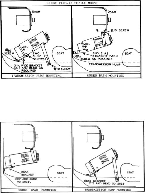
Figure 2-3. Deluxe Plug-in Mobile Mounting Kit Installation
2-24. MOBILE BRACKET KIT (MBK). This kit includes: One 9-inch and two 12-inch cadmium plated steel mounting bars with screws. Figure 2-4 illustrates how the transceiver can be hung under the dash, or mounted over the transmission hump. Each installation is different, so this must be left to the individual. Consult your dealer or friends with mobile experience if need be. The brackets can be cut easily and bent as required. The smaller No. 6x3/4 inch screws are for attaching the brackets to the sides or bottom of the transceiver. They will replace the No. 4x1/4 inch screws that came in the transceiver, thus allowing for the 1/8 inch thickness of the bracket. The No. 6 screws will make the brackets more secure than the original No. 4's would. The No. 14 screws are for securing the brackets to the under side of the dash, or to the transmission hump. No. 10 screws are also furnished in case the No. 14 screws are too large.
Figure 2-4. Mobile Bracket Kit Installation
2-25. INSTALLING D.C. POWER CABLE. The power cable should be run from the transceiver, through the bulkhead, and connected as close to the battery as is practical. The best way is to connect directly to the battery posts. Drill and tap into the lead terminal posts for 10-32 machine screws, and secure No. 10 terminal lugs under these screw heads. The advantage of doing this is that even if the battery clamps work loose, it will not
11

affect the transceiver connections, and the danger of intermittant transient voltage spikes will be reduced.
If drilling and tapping the battery posts is not practical, then connect the leads to the engine end of the battery cables. The negative cable will usually be found going to a bolt on the engine block, while the positive cable usually goes to a bolt on the starter solenoid. Use proper terminal lugs at these points for connecting the leads. The red lead goes to positive and the brown lead to negative. (If power cable has black and white leads, the black is negative, and the white is positive). A protective diode is built into the transceiver plug, and will open if polarity is inadvertantly connected wrong. As discussed in paragraph 2-4, the battery clamps should be cleaned and tightened. All electrical connections should likewise be checked and tightened.
2-26 INSTALLATION OF 25 AMP CIRCUIT BREAKER. The 25 ampere circuit breaker supplied with the kit should be installed in series with the positive lead. It is best to mount it close to the battery end of the cable, at some convenient place on the side of a metal panel or bracket. Short metal screws are supplied for this purpose. It is not important that the metal case of the circuit breaker be grounded, since there are no connections made to the case. Cut the positive red (or white) power lead, install No. 10 terminal lugs, and secure firmly to the circuit breaker with washers and nuts. Solder the terminal lugs.
2-27. OTHER D.C. INSTALLATIONS. In the event that you have not purchased the DMK, MBK, or DCC kits, your transceiver comes with two banana jacks for the positive battery lead, and are to be connected in parallel as shown in Figure 2-5. The banana plug connects to the negative battery lead. The battery leads should be of No. 10 or No. 12 gauge stranded wire of the automotive type. A 20 amp. fuse or circuit breaker should be installed in the positive lead. Figure 2-5 illustrates the proper connections required between the battery and the Atlas transceiver.
CAUTION IT IS EXTREMELY IMPORTANT THAT PROPER POLARITY BE OBSERVED. THE POSITIVE BATTERY LEAD MUST GO TO THE TWO TERMINALS CLEARLY MARKED ON BACK OF THE TRANSCEIVER. THE NEGATIVE BATTERY LEAD MUST GO TO THE TRANSCEIVER CHASSIS GROUND, AND THE BANANA PLUG IS FOR THIS PURPOSE. EVEN MOMENTARY CONNECTION OF THE WRONG POLARITY WILL DESTROY THE TRANSISTORS, AND VOID THE ATLAS WARRANTY.
Figure 2-5. D.C. Power Connections
12
2-28. FIXED STATION INSTALLATIONS
In fixed station installations, the use of the 220-CS eliminates the necessity for making D.C. power connections. The only requirement is that the Atlas Transceiver be firmly seated in the console. When installing the transceiver in the console, always make sure that the unit is pushed all the way into the console. This will insure that all power, Mic, and speaker connections are firmly made.
2-29. ANTENNAS
2-30. MOBILE ANTENNAS. The mobile antenna generally requires more critical adjustment than the home station antenna. This is because it operates over a more narrow bandwidth, and must therefore be adjusted very accurately for resonance. Also, the base impedance is seldom very close to 52 ohms. With the tube type transmitters the Pi matching network will adjust to fairly low impedances, but with a broadband solid state transmitter, such as is used in the Atlas transceivers, a close impedance match is necessary in order to operate at full power. Various claims about impedance are made by manufacturers of mobile antennas, but unfortunately our tests on all the most popular brands indicate that your chances of coming up with a close match are less than 1 to 10. Average base impedance is 18 to 23 ohms. Therefore, some method of transforming the antenna base impedance to 52 ohms is required. (See Section 5-3 for Model MT-1 Broadband Transformer.)
2-31.CAPACITYMATCHINGMETHOD.This is one method for impedance matching to the mobile antenna which works quite well. A capacitor is connected from the antenna base to ground. This capcitor is part of an L network which transforms the base impedance from a low value up to 52 ohms. The small amount of "1" required is actually "borrowed" from the lower part of the loading coil. The capacity value must be determined experimentally, and will vary from band to band, as well as from installation to installation.
On 75 meters, the capacity will generally need to be in the 1000 to 1500 picofarad range. On 40 meters, 300 to 400 picofarads and on 20 meters about 200 picofarads. A variable capacitor can be useful to determine what value is required or a collection of silver mica capacitors, some 100 pf's, 200's, 470's, and a 1000 pf can be paralleled in various combinations until the SWR comes down to a low figure. Once you know how much capacity your antenna needs, it is best to make up the permanent capacitor by paralleling two or more silver micas. This will divide the R.F. current and reduce the chances of overheating a single capacitor with too much current. Follow the procedure described in paragraph 2-14 when tuning the antenna.
2-32. NOISE SUPPRESSION. The subject of noise suppressing automotive ignition and alternator noise is beyond the scope of this manual, so it will only be mentioned briefly. Many cars will create very little interference in the IIF bands covered by the Atlas transceiver. Almost all cars now use resistance type ignition wire, and will probably create very little ignition noise. More likely the high pitched whine from the alternator will cause more trouble. Refer to the various amateur radio handbooks available from your dealer for information on noise suppression. It will usually be found in the mobile sections. Estes Engineering Co., 930 Marine Dr., Port Angeles, Wash. 98362, manufactures an excellent line of suppression kits which can help cure the more stubborn cases. It is quite likely that your dealer sells the Estes Engineering line also.
IMPORTANT: Make sure that the transceiver mounting brackets are well grounded to the transmission hump or bulkhead.
13
2.33. FIXED STATION ANTENNAS
On 10, 15, and 20 meters a doublet and most beam antennas will match quite well across the entire band. On 40 meters a doublet tuned for phone band center will match quite well across the band. On 75 meters the average doublet will have a bandwidth of about 100 kc for SWR of 1.5 or less. To work the entire band with full efficiency will require an antenna tuner. On 160 meters an antenna tuner, or at least some kind of matching system will be essential, since even at resonance it is unlikely that the feed point will be near 52 ohms. In any case, it is always best to optimize the antenna system for the frequency where you do most of your operating.
2.34. ANTENNA TUNER OR. "MATCH BOX." An antenna tuner can be a very useful device to compensate for antenna mismatch. This may be especially true if you happen to have a favorite antenna that has been working just fine with the old tube rig, and now you discover the new solid state rig doesn't like the old antenna. Refer to the antenna handbooks for helpful data, or ask your dealer about antenna tuners now on the market.
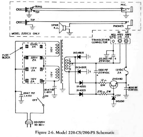
Figure 2-6. Model 220-CS/200-PS Schematic
14
SECTION 3
OPERATION
3-1. INTRODUCTION
This section provided instructions for operating the ATLAS 210x/215x transceiver and identifies operating controls, indicators, and connections. Front panel controls and indicators are shown and described in Figure 3-1. Rear panel controls and connections are shown and described in Figure 3-2.
3-2. CONTROLS
3-3. POWER SUPPLY ON/OFF, MOBILE OPERATION
The Function Switch has an OFF position which turns off the DC supply to the low current circuits. The high current circuits (Driver and Power Amplifier) remain connected to the DC supply line, but are automatically biased off when the low current line is turned off.
3-4. POWER SUPPLY ON/OFF, 220-CS/200PS.
The 220-CS/200-PS supplies have an ON/OFF toggle switch which turns off the AC supply line. This switch should be used rather than the Function Switch OFF position.
3-5. FUNCTION SWITCH
The first position is the OFF position and is used for mobile operation. The REC. position places the transceiver in receive mode. Press-to-talk and VOX circuits are operative in this position. TRANS position switches the transceiver into transmit mode in the event a Mic. without a press-to-talk switch is used, or if you wish to hold-in transmit mode without having to hold the push-to-talk button down. The CW position is also transmit mode except that the Mic. Gain control now becomes a Carrier Insertion control and carrier frequency has been shifted about 800 Hertz. (See CW Transmission)
3-6. A. F. GAIN The A. F. GAIN control is used to control audio volume in receive
mode.
3-7. R. F. GAIN
The purpose of the R.F. Gain control is to permit decreasing the between speech noise level, thus providing more pleasing reception. The AGC system in the ATLAS transceiver has a tremendous dynamic signal range. With full R.F. Gain, sensitivity will automatically return to maximum in the absence of a signal, accompanied by a natural increase in background noise.
You may find it annoying to hear the noise level increase every time the person being received pauses between words or sentences. There are really only two conditions when the R.F. Gain control needs to be on full. One is when you are scanning the band and want to hear weak as well as strong signals. But, a lot of the time you can turn the R.F. Gain down a bit, increase the A.F. Gain correspondingly, and realize more pleasing reception.
3-8. BAND SELECTOR AND TUNING DIAL, MODEL 21 Ox
The numbers on the band selector read in MegaHertz for the respective bands: 3.5 for the 80 meter band, 7.0 for 40 meters, etc.
15
 Loading...