


GUARDIAN PRO™
180 Series
Models MLG180B
MLG180W
Meets the ENERGY STAR® guidelines when used with 120 W Max bulbs.
Features
•Turns on lighting when motion is detected.
•Automatically turns lighting off.
•Photocell keeps the lighting off during daylight hours.
•LED indicates motion was sensed (day or night).
This package includes:
Bulb |
|
|
|
Holders |
|
Rubber Plug |
|
|
|
Plastic Hanger |
|
Cover |
|
|
|
Plate |
Sensor |
|
|
|
|
||
Light Control |
2 Wire |
||
Connectors |
|||
|
|
||
Mounting Bolt |
Mounting Strap |
|
|
Gasket
6 Screws
(3 sizes included)
Requirements
•The light control requires 120-volts AC.
•If you want to use Manual Mode, the control must be wired through a switch.
•Some codes require installation by a qualified electrician.
•This product is intended for use with the enclosed gasket and with a junction box marked for use in wet locations.
OPERATION
Mode: |
On-Time |
Works: Day |
Night |
Test |
5 Seconds |
x |
x |
Auto |
1, 5, or 10 Minutes |
|
x |
Manual |
To Dawn* |
|
x |
* resets to Auto Mode at dawn.
Note: When first turned on wait about 1 1/2 minutes for the circuitry to calibrate.
TEST
Put the ON-TIME switch on the bottom |
|
ON-TIME |
|
|||||
of the sensor in the TEST position. |
|
|
|
|
|
|
|
|
|
|
|
|
|
|
|
|
|
|
|
10 5 1 TEST |
||||||
|
|
|
|
|
|
|
|
|
AUTO |
|
|
|
|
|
|
|
|
|
|
|
|
|
|
|
|
|
Put the ON-TIME switch in the 1, 5, |
ON-TIME |
|||||||
or 10 minute position. |
|
|
|
|
|
|
|
|
|
|
|
|
|
|
|
|
|
|
|
|
|
|
|
|
|
|
|
10 5 1 TEST |
|||||||
MANUAL MODE |
|
|
|
|
|
|
|
|
Manual mode only works at night because daylight returns the sensor to AUTO.
Flip the light switch off for one second then back on to toggle between AUTO and MANUAL MODE.
Manual mode works only with the ON-TIME switch in the 1, 5, or 10 position.
1 Second OFF
then...
... back on.
|
240-026-A |
© 2008 Atlas Lighting Products, Inc. |
598-1092-02 |
Mode Switching Summary
|
TEST |
|
|
|
|
Move ON-TIME Switch to |
||
|
||||||||
|
|
|
|
|
|
|||
|
|
|
|
|
|
|
|
1, 5, or 10 minutes |
|
|
|
|
|
|
|
||
|
AUTO |
|
|
|
|
|
Flip light switch off |
|
|
|
|
|
|
|
|
|
|
|
|
|
|
|
|
|
|
|
|
|
|
|
|
|
|
|
for one second then |
|
|
|
|
|
|
|
|
back on* |
MANUAL MODE |
|
|
|
|||||
|
|
|
|
|||||
*If you get confused while switching modes, turn the power off for one minute, then back on. After the calibration time the control will be in the AUTO mode.
INSTALLATION
For easy installation, select an existing light with a wall switch for replacement.
For best performance, mount the fixture about 8 ft. (2.4 m) above the ground.NOTE: If fixture is mounted higher than 8 ft. (2.4 m), aiming the sensor down will reduce coverage distance.
|
|
|
|
|
|
Wall Mount |
Eave Mount |
||||
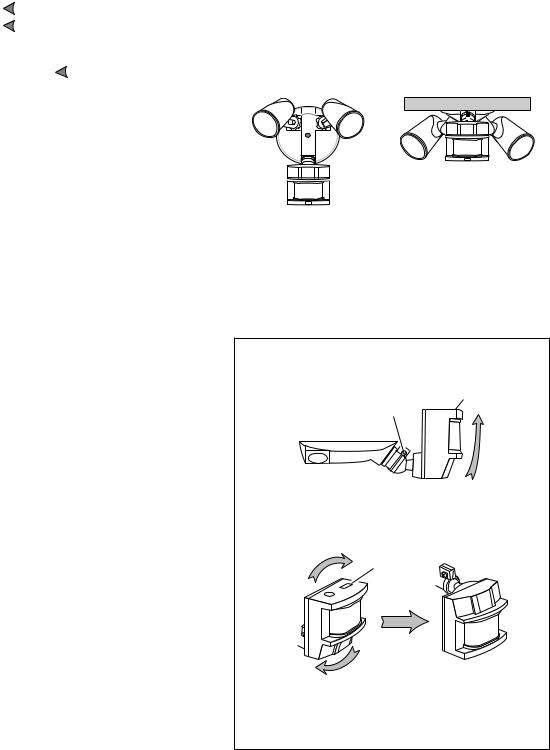
For under eave installation, the sensor head must be rotated as shown in the next two steps for proper operation and to avoid the risk of electrical shock.
For eave mount only:
Swing the sensor head towards the clamp screw joint.
Controls
Clamp Screw
Then rotate the sensor head clockwise 180° so the controls face down.
Controls
Controls 
If the sensor pops out of the ball joint, loosen the clamp screw and push the sensor back into the ball joint. Tighten the clamp screw when done.
598-1092-02

Wire the Light Control
 WARNING: Turn power off at circuit breaker or fuse.
Remove the existing light fixture.
Install the mounting strap as shown using two screws that fit your junction box.
The plastic hanger can be used to hold the fixture while wiring. The small end of the plastic hanger can be threaded through the hole in the center of the cover plate. The small end then goes into one of the slots on the mounting strap.
Route the light control’s wires through the large gasket holes.
Twist the junction box wires and fixture wires together as shown. Secure with wire connectors.
Mounting |
|
|
|
Black to |
|
White to |
|
Strap |
Black |
|
White |
|
|
|
|
Rubber
Plug
Mounting
Bolt
Gasket
Junction box ground wire to green ground screw on fixture.
Mount the Light Control
Align the light control cover plate and cover plate gasket. Secure with the mounting bolt.
Push the rubber plug firmly into place.
If a wet location junction box was not used, caulk the wall plate mounting surface with silicone weather sealant.
To avoid water damage and electrical shock, keep bulb holders 30° below horizontal.
|
Keep bulbs at least |
|
1" (25 mm) from the |
Lock Nut |
sensor.Do not allow |
|
the bulbs to block |
Lens |
the lens. |
Adjust the bulb holders by loosening the lock nuts but do not rotate the bulb holders more than 180° from the factory setting.When screwing in the floodlamps, do not overtighten.
598-1092-02
 Loading...