


Copco Stationary Air Compressors

Instruction book
2920 1521 00 1
Atlas Copco Stationary Air Compressors
Instruction book
SF1 - SF2 - SF4 Skid -Tank-mounted
SF6 - SF8 Twin
SF6 - SF8 - SF11 - SF15 Multi
Copyright 2003, Atlas Copco Airpower n.v, Antwerp, Belgium.
Any unauthorized use or copying of the contents or any part thereof is prohibited. This applies in
particular to trademarks, model denominations, part numbers and drawings.
This instruction book meets the requirements for instructions specified by the machinery directive
98/37/EC and is valid for CE as well as non-CE labelled machines.
No. 2920 1521 00
Registration code: APC SF / 38 / 980
2003-10 www.atlascopco.com
Note: The PED instructions for this machine are included at the end of the book.

Instruction book
2920 1521 00 2
This instruction book describes how to handle the machines to ensure safe operation, optimum
efficiency and long service life.
Read this book before putting the machine into operation to ensure correct handling, operation
and proper maintenance from the beginning. The maintenance schedule comprises measures for
keeping the machine in good condition.
Keep the book available for the operator and make sure that the machine is operated and that
maintenance is carried out according to the instructions. Record all operating data, maintenance
performed, etc. in an operator's logbook available from Atlas Copco. Follow all relevant safety
precautions, including those mentioned on the cover of this book.
Repairs must be carried out by trained personnel from Atlas Copco who can be contacted for any
further information.
In all correspondence mention the type and the serial number, shown on the data plate.
For all data not mentioned in the text, see sections "Preventive maintenance schedule" and "Principal
data".
The company reserves the right to make changes without prior notice.

Instruction book
2920 1521 00 3
1 LEADING PARTICULARS................................................................................................................... 5
1.1 General description........................................................................................................................ 5
1.1.1 Compressor variants ............................................................................................................... 5
1.1.2 Compressor elements (Fig. 1.1).............................................................................................. 5
1.2 Air flow ........................................................................................................................................... 9
1.3 Cooling and condensate drain systems (Fig. 1.9) ......................................................................... 9
1.4 Regulating system on SF Skid - Tank-mounted - Twin ............................................................... 10
1.5 Regulating system on SF Multi .................................................................................................... 11
1.5.1 Controlling the compressor ................................................................................................... 11
1.5.2 Protecting the compressor .................................................................................................... 11
1.5.3 Monitoring components subject to service............................................................................ 11
1.5.4 Automatic restart after voltage failure ...................................................................................11
1.5.5 Control panel (Fig. 1.11) ....................................................................................................... 12
1.5.6 Display – keys ....................................................................................................................... 13
1.5.7 Function keys (5-Fig. 1.11) ................................................................................................... 13
1.6 Electric cabinet on SF Multi ......................................................................................................... 15
1.7 Air dryer on SF Full-Feature (Fig. 1.15)....................................................................................... 16
2 INSTALLATION ................................................................................................................................. 17
2.1 Dimension drawings (Figs. 2.1 up to 2.5) ....................................................................................17
2.2 Installation proposal (Fig. 2.6) ..................................................................................................... 22
2.3 Electrical connections .................................................................................................................. 24
2.4 Pictographs .................................................................................................................................. 27
3 OPERATING INSTRUCTIONS .......................................................................................................... 28
3.1 Initial start-up ............................................................................................................................... 28
3.2 Starting......................................................................................................................................... 28
3.2.1 Multi....................................................................................................................................... 28
3.2.2 Skid - Tank-mounted - Twin .................................................................................................. 28
3.3 During operation .......................................................................................................................... 29
3.3.1 Multi....................................................................................................................................... 29
3.3.2 Skid - Tank-mounted - Twin .................................................................................................. 29
3.4 Stopping....................................................................................................................................... 29
3.4.1 Multi....................................................................................................................................... 29
3.4.2 Skid - Tank-mounted - Twin .................................................................................................. 29
3.5 Taking out of operation at end of compressor service life........................................................... 29
4 MAINTENANCE ................................................................................................................................. 30
4.1 Compressor drive motors ............................................................................................................ 30
4.2 Preventive maintenance schedule for the compressor................................................................ 30
5 ADJUSTMENTS AND SERVICING PROCEDURES ........................................................................ 32
5.1 Air filter (1-Figs. 1.7/1.8) .............................................................................................................. 32
5.2 Belt exchange/tensioning (Fig. 5.1) ............................................................................................. 32
5.3 Coolers......................................................................................................................................... 32
5.4 Safety valve ................................................................................................................................. 33
6 PROBLEM SOLVING ........................................................................................................................ 34
7 PRINCIPAL DATA ............................................................................................................................. 35
7.1 Electric cable size for SF1-8 ........................................................................................................ 35
7.2 Electric cable size for SF 6-15 Multi ............................................................................................ 35
7.3 Overload relays for SF1-8............................................................................................................ 36
7.4 Overload relays for SF6-15 Multi ................................................................................................. 36
7.5 Main fuses for SF1-8.................................................................................................................... 37
7.6 Main fuses for SF6-15 Multi......................................................................................................... 37
7.7 Reference conditions/limitations .................................................................................................. 37
7.8 SF1-4 8bar 50 Hz 1) ................................................................................................................... 38
7.9 SF2-4 10 bar 50 Hz 1) ................................................................................................................ 38
7.10 SF1-4 100 psi 60 Hz 1)............................................................................................................. 38
7.11 SF2-4 145 psi 60 Hz 1)............................................................................................................. 38
7.12 SF6-15 Multi 8 bar 50 Hz 1)...................................................................................................... 39
7.13 SF6-15 Multi 10 bar 50 Hz 1).................................................................................................... 39
7.14 SF6-15 Multi 100 psi 60 Hz 1) .................................................................................................. 39
7.15 SF6-15 Multi 125 psi 60 Hz 1) .................................................................................................. 40

Instruction book
2920 1521 00 4
7.16 SF6-15 Multi 145 psi 60 Hz 1) .................................................................................................. 40
8 REGULATOR FUNCTIONS FOR SF MULTI .................................................................................... 41
8.1 Menu-driven control programs..................................................................................................... 41
8.1.1 Function of control programs ................................................................................................ 42
8.1.2 Main screen........................................................................................................................... 42
8.1.3 Calling up other menus ......................................................................................................... 44
8.2 Quick look at actual compressor status ....................................................................................... 44
8.3 Status data menu......................................................................................................................... 45
8.3.1 No message exists ................................................................................................................ 45
8.3.2 A shut-down message exists ................................................................................................45
8.3.3 A warning message exists .................................................................................................... 46
8.3.4 A service warning message exists ........................................................................................ 47
8.4 Measured data menu................................................................................................................... 47
8.5 Counters menu ............................................................................................................................ 48
8.6 Test menu .................................................................................................................................... 48
8.7 Modify parameters menu ............................................................................................................. 49
8.8 Modifying parameters .................................................................................................................. 49
8.8.1 Modifying the pressure bands ............................................................................................... 50
8.9 Modifying protection settings ....................................................................................................... 51
8.9.1 Checking protections for compressor modules..................................................................... 51
8.9.2 Modifying protections for Dryer LAT on Full-Feature machines ........................................... 52
8.10 Modifying service plans ............................................................................................................. 52
8.11 Programming Clock function...................................................................................................... 54
8.11.1 Programming start/stop/pressure band commands............................................................ 54
8.11.2 To activate/deactivate the timer .......................................................................................... 56
8.11.3 To modify a command......................................................................................................... 56
8.11.4 To add a command ............................................................................................................. 57
8.11.5 To delete commands........................................................................................................... 58
8.12 Configuration menu.................................................................................................................... 59
8.12.1 Programming compressor control modes ........................................................................... 60
8.13 Service menu ............................................................................................................................. 60
8.14 Saved data menu....................................................................................................................... 63
8.15 Programmable settings.............................................................................................................. 64
8.15.1 Regulation settings.............................................................................................................. 64
8.15.2 Service settings ................................................................................................................... 65
9 CONVERSION LIST OF SI UNITS INTO US/BRITISH UNITS ......................................................... 65
Instruction book
2920 1521 00 5
1 LEADING PARTICULARS
1.1 General description
SF1 up to SF15 are stationary, oil-free compressors driven by an electric motor.
1.1.1 Compressor variants
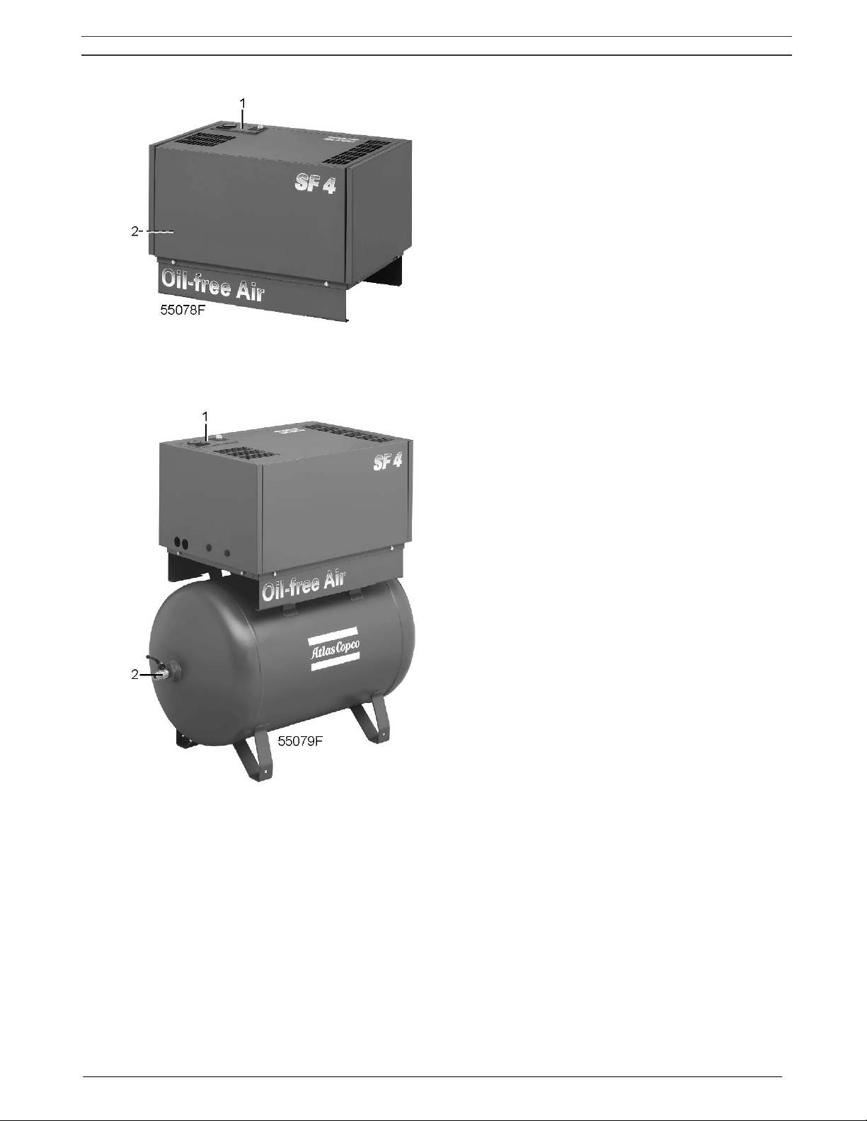
SF Skid (Fig. 1.2)
The components of the compressor are housed in a bodywork with removable front/top panel. The
compressor is mounted on a frame designed to allow easy installation at the required spot.
SF Tank-mounted (Fig. 1.3)
The components of the compressor are housed in a bodywork with removable front/top panel. The
compressor is mounted on an air receiver.
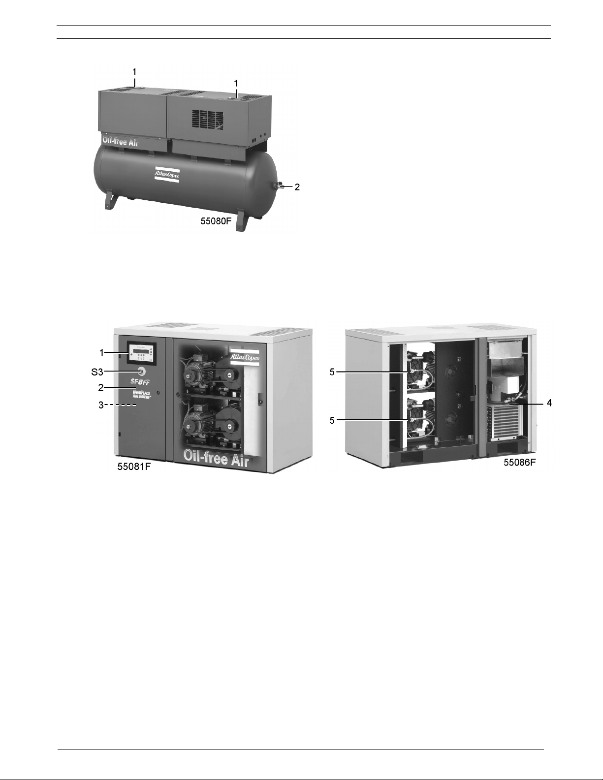
SF Twin (Fig. 1.4)
Two compressor modules are mounted on an air receiver. Each module is provided with its own control
panel.
SF Multi Pack
The compressors have two up to four compressor modules enclosed in a sound-insulated bodywork.
The front door comprises an Elektronikon regulator including the start and stop buttons. An
emergency stop button is also provided. An electric cabinet comprising the motor starter is installed
behind the front door.
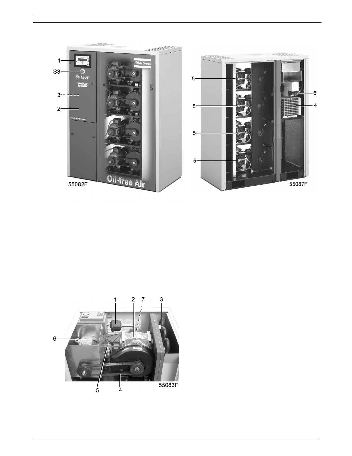
SF Multi Full-Feature (Figs. 1.5 and 1.6)
Full-Feature compressors are Pack compressors additionally provided with an air dryer integrated in
the bodywork. The dryer removes moisture from compressed air by cooling the air to near freezing
point and automatically draining the condensate. See section 1.7.
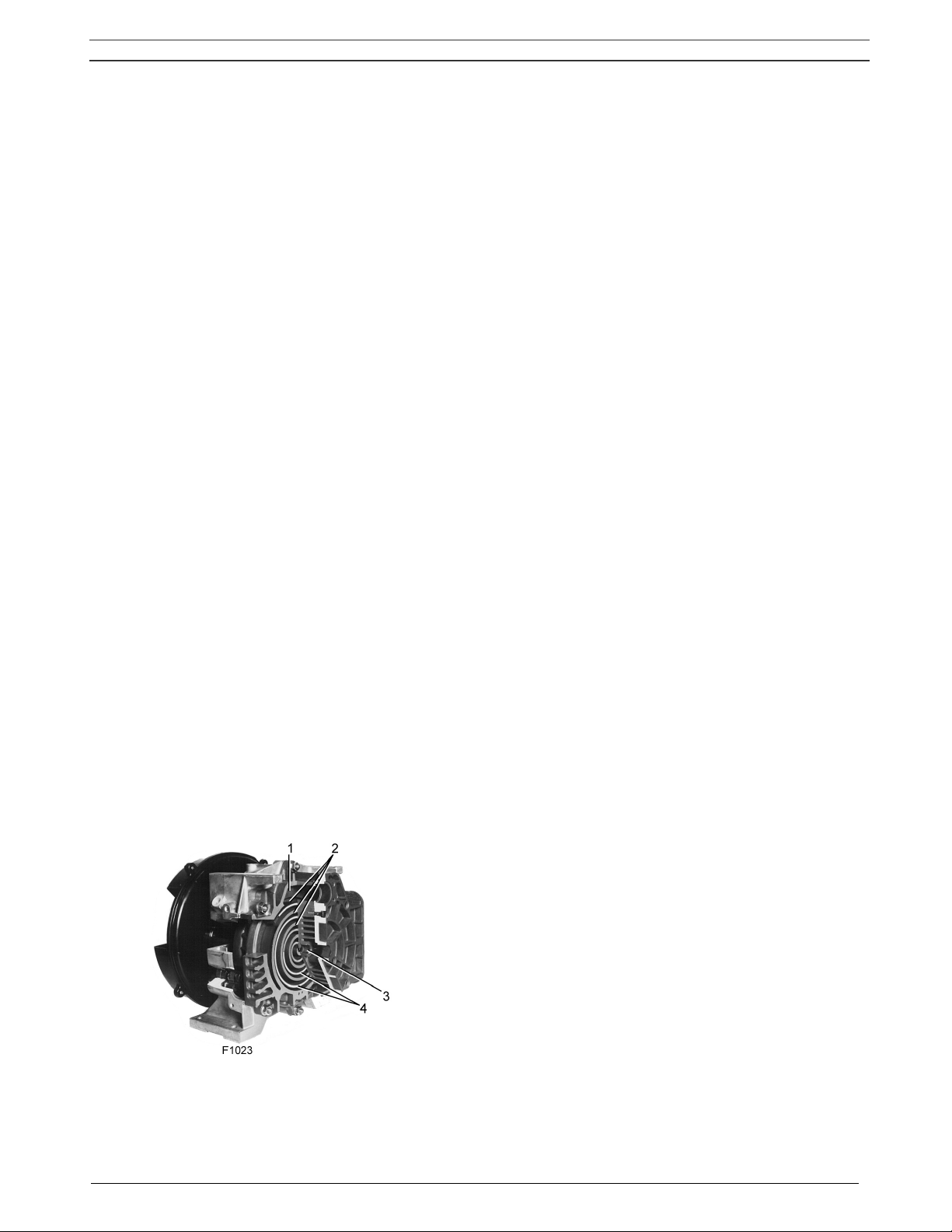
1.1.2 Compressor elements (Fig. 1.1)
Each compressor element consists of a fixed scroll-shaped housing and a scroll-shaped rotor. Air
enters the compressor element through inlet opening (1). Once the air is drawn in, the orbiting scroll
(4) seals the inlet opening and forces the air into a continuously decreasing space. As scroll (4) keeps
orbiting, this process of compression is constantly repeated, resulting in discharging of oil-free
compressed air through outlet opening (3).
1 Air inlet
2 Fixed scroll
3 Compressed air outlet
4 Orbiting scroll
Fig. 1.1 Compressor element
Instruction book
2920 1521 00 6
1 Control panel
2 Air outlet valve
Fig. 1.2 SF4 Skid
1 Control panel
2 Air outlet valve
1.3 SF4 Tank-mounted
Instruction book
2920 1521 00 7
1 Control panels
2 Air outlet valve
Fig. 1.4 SF Twin
1 Elektronikon regulator
2 Electric cabinet
3 Air outlet valve
4 Dryer (on Full-Feature)
5 Compressor modules
S3 Emergency stop button
Fig. 1.5 SF8FF Multi
Instruction book
2920 1521 00 8
1 Elektronikon regulator
2 Electric cabinet
3 Air outlet valve
4 Dryer (on Full-Feature)
5 Compressor modules
6 Safety valve (ASME)
S3 Emergency stop button
Fig. 1.6 SF15FF Multi
1 Air filter
2 Compressor element
3 Air cooler
4 Belts
5 Safety valve
6 Drive motor
7 Safety valve
Fig. 1.7 Details of a compressor module on SF Tank-mounted

Instruction book
2920 1521 00 9
1 Air filter
2 Drive motor
3 Compressor element
4 Compressed air outlet
5 Safety valve (CE)
Fig. 1.8 Details of a compressor module on SF Multi
1.2 Air flow
Air is drawn through the air filter into the compressor modules and is compressed. Compressed air is
discharged through the check valve and air cooler towards the air net.
1.3 Cooling and condensate drain systems (Fig. 1.9)
Each compressor element is cooled by a fan. The fan is mounted on the drive shaft of the compressor
element. The cooling air is blown over the compressor element and air cooler via a duct.
For SF Multi two fans, driven by electric motors, expel warm air from the bodywork.
SF Multi have a condensate trap, with an automatic condensate outlet (2) and a manual drain valve
(1).
1 Manual condensate drain valve
2 Automatic condensate outlet
Fig. 1.9 Condensate drains on SF Multi
Instruction book
2920 1521 00 10
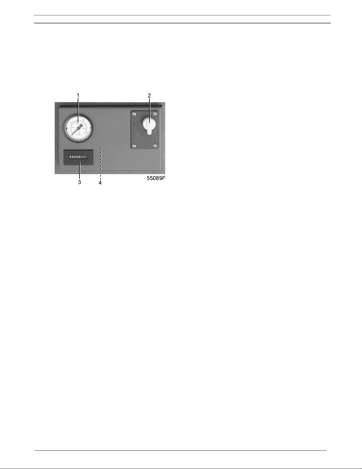
1.4 Regulating system on SF Skid - Tank-mounted - Twin
The air net pressure is kept within limits by a pressure switch mounted in the cabinet below the control
panel (Fig. 1.10). The switch is connected to the air outlet and electrically connected in the circuit of
the drive motor. The switch opens and closes its contacts at pre-set pressures.
1 Pressure gauge
2 On/off switch
3 Hourmeter
4 Air pressure switch/circuit breaker
Fig. 1.10 Control panel SF Skid - Tank-mounted - Twin
When the contacts are closed, the circuit to the drive motor is made: the compressor is operating. The
air output is maximum.
When the pressure reaches the pre-set maximum, the circuit to the drive motor is broken, causing the
compressor to stop. The air output is stopped.
Protecting the compressor
The compressor will be shut down in case temperature switch (TSHH11-Fig. 2.7) trips.
Warning
Before carrying out any inspection or repair, stop the compressor, switch off the voltage, open the
isolating switch and depressurize the compressor.

Instruction book
2920 1521 00 11
1.5 Regulating system on SF Multi
SF Multi are provided with an Elektronikon® regulator (Fig. 1.11) to control the compressor.
The following is a short description of the main functions of the regulator. Consult section 8 for a
detailed description of all functions.
1.5.1 Controlling the compressor
The Elektronikon regulator keeps the net pressure within programmable limits by starting and stopping
the compressor modules, depending on the air consumption. The regulator distributes the running
time among the compressor modules, taking into account the availability and number of running hours
of each compressor module.
When the compressor has stopped automatically and the net pressure decreases, the regulator will
start a compressor module before the net pressure has dropped to the starting pressure to prevent the
net pressure from falling under the programmed minimum level.
1.5.2 Protecting the compressor
If one or more compressor modules are shut down due to a protection function a warning message will
be shown on the display.
The compressor will be shut down in case temperature switch (TSHH20-Fig. 2.8) trips. See also
section 8.3.2.
Warning
Before carrying out any inspection or repair, stop the compressor, switch off the voltage, open the
isolating switch and depressurize the compressor.
After remedying, switch on the voltage and press the key “Reset” (F3).
1.5.3 Monitoring components subject to service
A number of service operations are grouped in plans (called Service plans I, A, B and D). Each
Service plan has a programmed time interval. If a time interval is exceeded, a message will appear on
the display to warn the operator to carry out the service actions belonging to that plan.
1.5.4 Automatic restart after voltage failure
The regulator has a built-in function to automatically restart the compressor if the voltage is restored
after voltage failure. For compressors leaving the factory, this function is made inactive. If desired,
the function can be activated. Consult Atlas Copco.
Instruction book
2920 1521 00 12
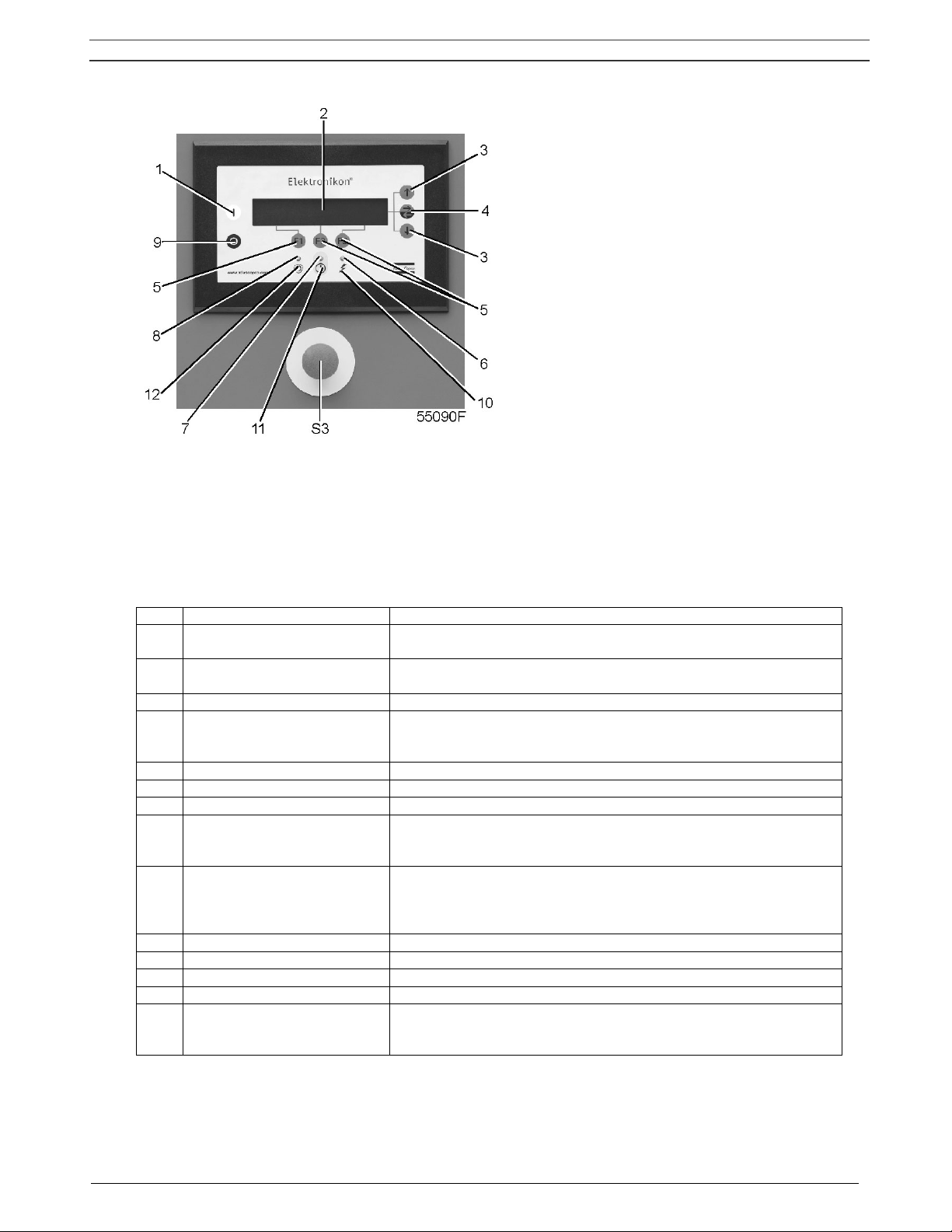
Fig. 1.11 Elektronikon regulator on SF Multi
1.5.5 Control panel (Fig. 1.11)
To control the compressor and to read and modify programmable parameters, the regulator is provided with a
control panel including:
Ref Designation Function
1 Start button
Push button to start the compressor. LED (8) lights up indicating
that the regulator is operative (in automatic operation).
2 Display
Indicates messages concerning the compressor operating
condition, a service need or a fault.
3 Scroll keys Keys to scroll through the display.
4 Tabulator key
Key to select the parameter indicated by a horizontal arrow.
Only the parameters followed by an arrow pointing to the right
are accessible for modifying.
5 Function keys Keys to control and program the compressor.
6 Voltage on LED Indicates that the voltage is switched on.
7 General alarm LED Is alight in case of a warning condition, see section 8.3.
7 General alarm LED
Blinks in case of shut-down condition, if a sensor with shut-
down function is out of order or after an emergency stop. See
section 8.3.
8 Automatic operation LED
Indicates that the regulator is automatically controlling the
compressor: the compressor is stopped and restarted
depending on the air consumption and the limitations
programmed in the regulator.
9 Stop button Push button to stop the compressor. LED (8) goes out.
10 Pictograph Voltage on.
11 Pictograph Alarm condition.
12 Pictograph Automatic operation.
S3 Emergency stop button
Push button to stop the compressor immediately in case of
emergency. After remedying the trouble, unlock the button by
pulling it out.
Instruction book
2920 1521 00 13
1.5.6 Display – keys
Compressor Outlet 7.0 bar
Compressor Running
↓
Menu - - - -
F1 F2 F3
Fig. 1.12 Typical example of a display
Operating condition of a compressor module
The symbols shown above key F3 indicate the operating condition of each control module, see also section
8.1.2:
Symbol Indicates
-
that the compressor module is available (ready to run), each
symbol stands for a compressor module (the left symbol stands for
the lowest mounted module, the right symbol stands for the
highest module)
▄ that the compressor module is running
- (blinking)
that the compressor module is not available (due to minimum stop
time or too many starts)
* (blinking) that the compressor module is shut-down
Scroll keys (3-Fig. 1.11)
These keys, labelled with vertical arrows, allow to scroll through the display.
As long as a downwards pointing arrow is shown at the utmost right position of the display, the key (3) with
the same symbol can be used to see the next item.
As long as an upwards pointing arrow is shown at the utmost right position of the display, the key (3) with the
same symbol can be used to see the previous item.
Tabulator key (4-Fig. 1.11)
This key, labelled with two horizontal arrows, allows the operator to go to the next field of the display, e.g.
during modifying of programmable parameters.
1.5.7 Function keys (5-Fig. 1.11)
The keys are used:
- To call up or program settings
- To reset an active shut-down or service message, or an emergency stop
- To have access to all data collected by the regulator
The function keys allow to make the required selection from a menu of possibilities. The functions of the keys
vary depending on the displayed menu. The actual function is abbreviated and indicated on the bottom line of
the display just above the relevant key. Only the active and relevant functions at a moment are shown:
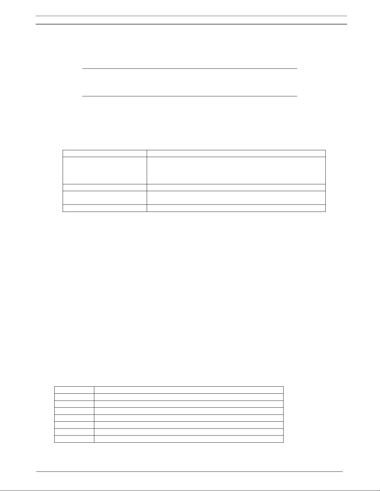
Designation Function
Back To return to a previously shown option or menu
Cancel To cancel a programmed setting when programming parameters
Delete To delete compressor start/stop commands
Extra To find the module configuration of the regulator
Help To find the Atlas Copco internet address
Limits To show limits for a programmable setting
Mainscreen To return from a menu to the main screen
Instruction book
2920 1521 00 14
Designation Function
Menu Starting from the main screen, to have access to submenus
Menu Starting from a submenu, to return to a previous menu
Modify To modify programmable settings
Program To program modified settings
Reset To reset a timer or message
Return To return to a previously shown option or menu
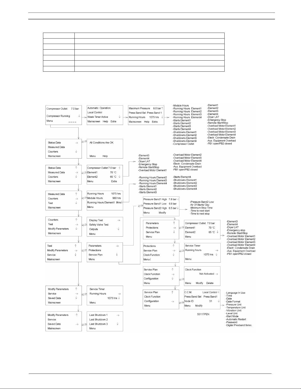
Selecting a menu
To facilitate controlling the compressor, menu-driven programs are implemented in the electronic module.
Use the function keys (5) to select the menus in order to program and monitor the compressor. See also
section 8.
Fig. 1.13 Menu flow, SF Multi
Instruction book
2920 1521 00 15
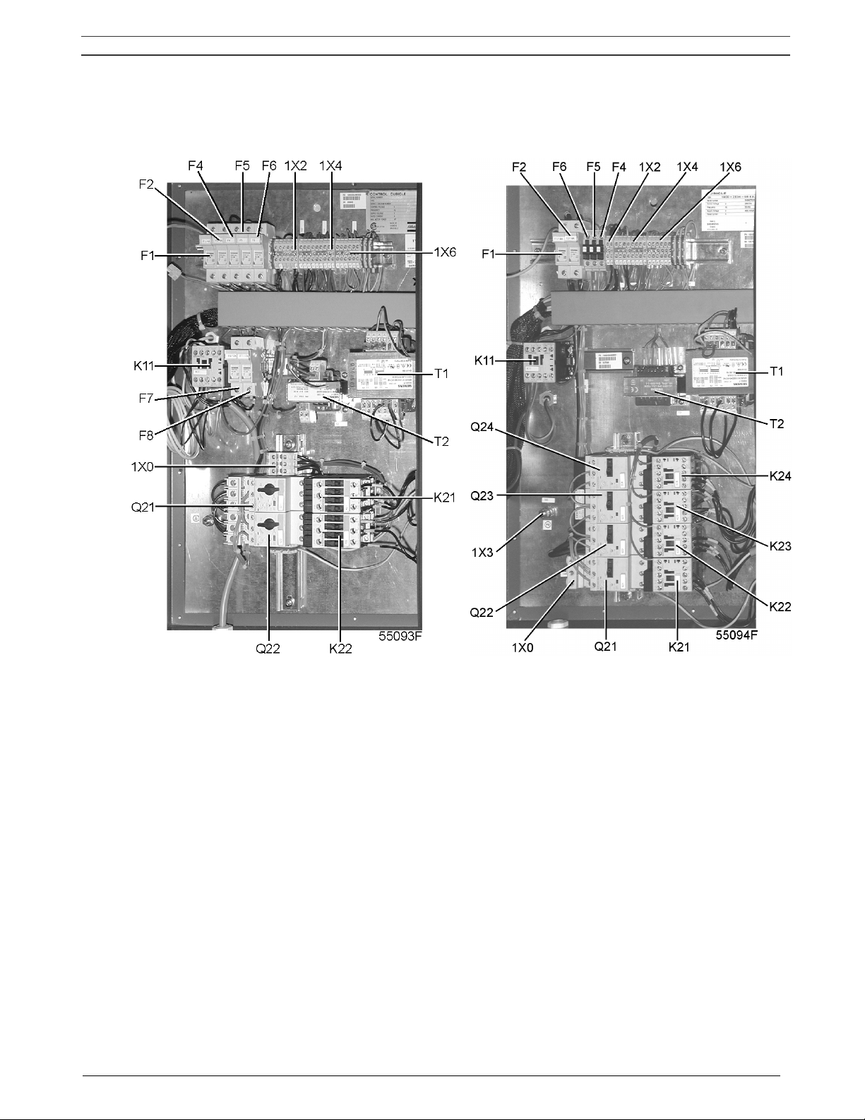
1.6 Electric cabinet on SF Multi
F1/8 Fuses
K11 Auxiliary contactor, dryer
K21/24 Contactors
Q21/24 Circuit breakers
T1/2 Transformers
1X0 Terminal strip, mains supply
1X2 Terminal strip, dryer
1X3/6 Terminal strips
Fig. 1.14 Electric cabinets, SF Multi
Instruction book
2920 1521 00 16
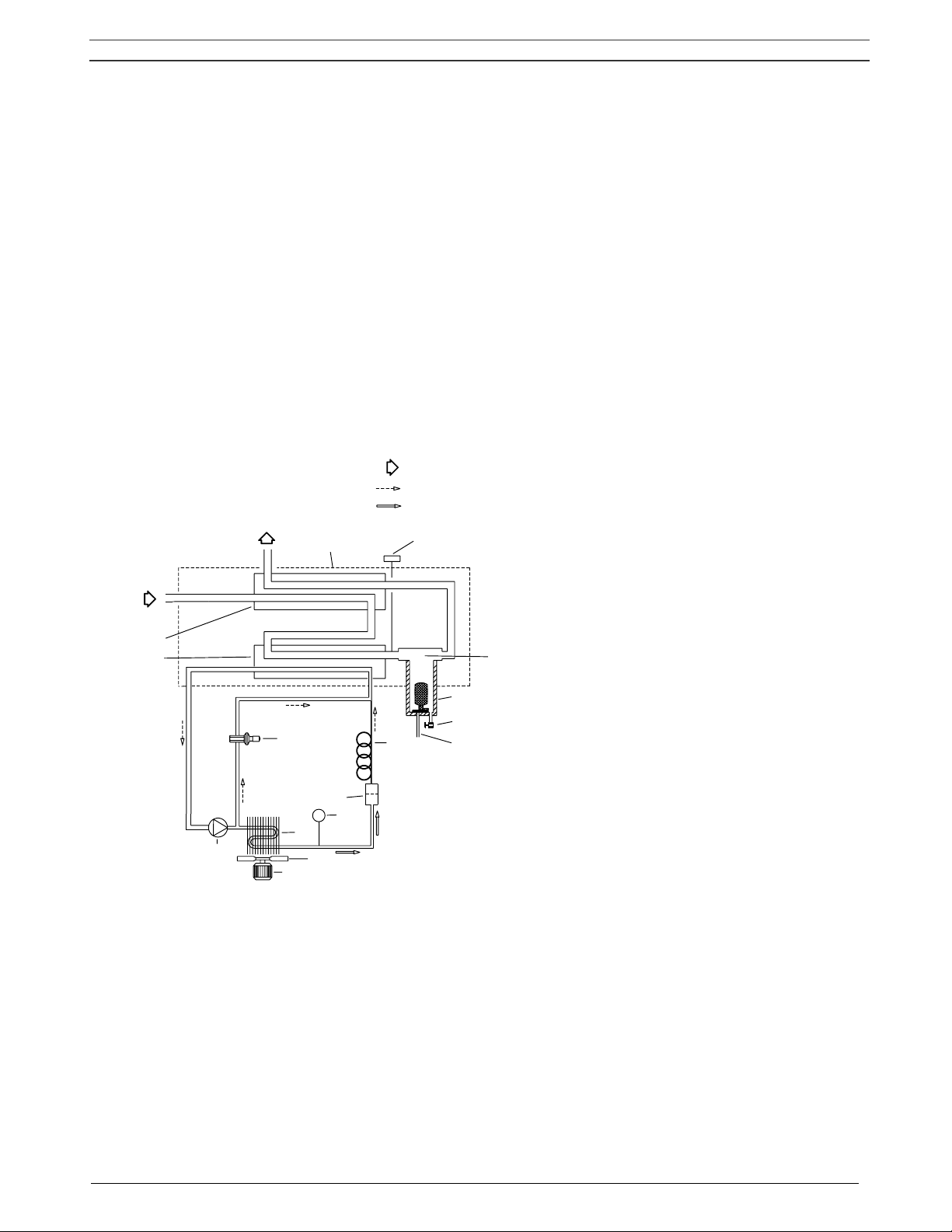
1.7 Air dryer on SF Full-Feature (Fig. 1.15)
Compressed air circuit
Wet compressed air enters heat exchanger (13) and is cooled by the outgoing, cold, dried air. Water in the
incoming air starts to condense. The air then flows through heat exchanger (11) where the refrigerant
evaporates and withdraws heat from the air. More water in the air condenses. The cold air then flows
through condensate separator (3) where the condensate is separated from the air. The condensate is
automatically drained through outlet (5). The cold, dried air then flows through heat exchanger (13), where it
is warmed up by the incoming air.
Refrigerant circuit
Compressor (M1) delivers hot, high-pressure refrigerant gas which flows through condenser (9) where most
of the refrigerant condenses.
The liquid flows through liquid refrigerant dryer/filter (12) to capillary tube (7). The refrigerant leaves the
capillary tube at evaporating pressure.
The refrigerant enters evaporator (11) where it withdraws heat from the compressed air by further evaporation
at constant pressure. The heated refrigerant leaves the evaporator and is sucked in by the compressor.
AO
AI
5
6
4
3
2
1
13
11
12
REFRIGERANT LIQUID (3)
REFRIGERANT GAS (2)
AIR (1)
50972D
7
10
S3
9
8
M2
M1
Text on Fig. 1.15
(1) Air
(2) Refrigerant gas
(3) Refrigerant liquid
AI Wet air inlet 5 Automatic condensate drain
AO Dry air outlet 6 Manual condensate drain valve
M1 Refrigerant compressor 7 Capillary tube
M2 Condenser fan motor 8 Condenser cooling fan
S3 Fan control switch 9 Refrigerant condenser
1 Pressure dewpoint sensor 10 Hot gas by-pass valve
2 Insulating block 11 Air/refrigerant heat exchanger/evaporator
3 Condensate separator 12 Liquid refrigerant dryer/filter
4 Condensate trap 13 Air/air heat exchanger
Fig. 1.15 Dryer on SF Full-Feature
Instruction book
2920 1521 00 17
2 INSTALLATION
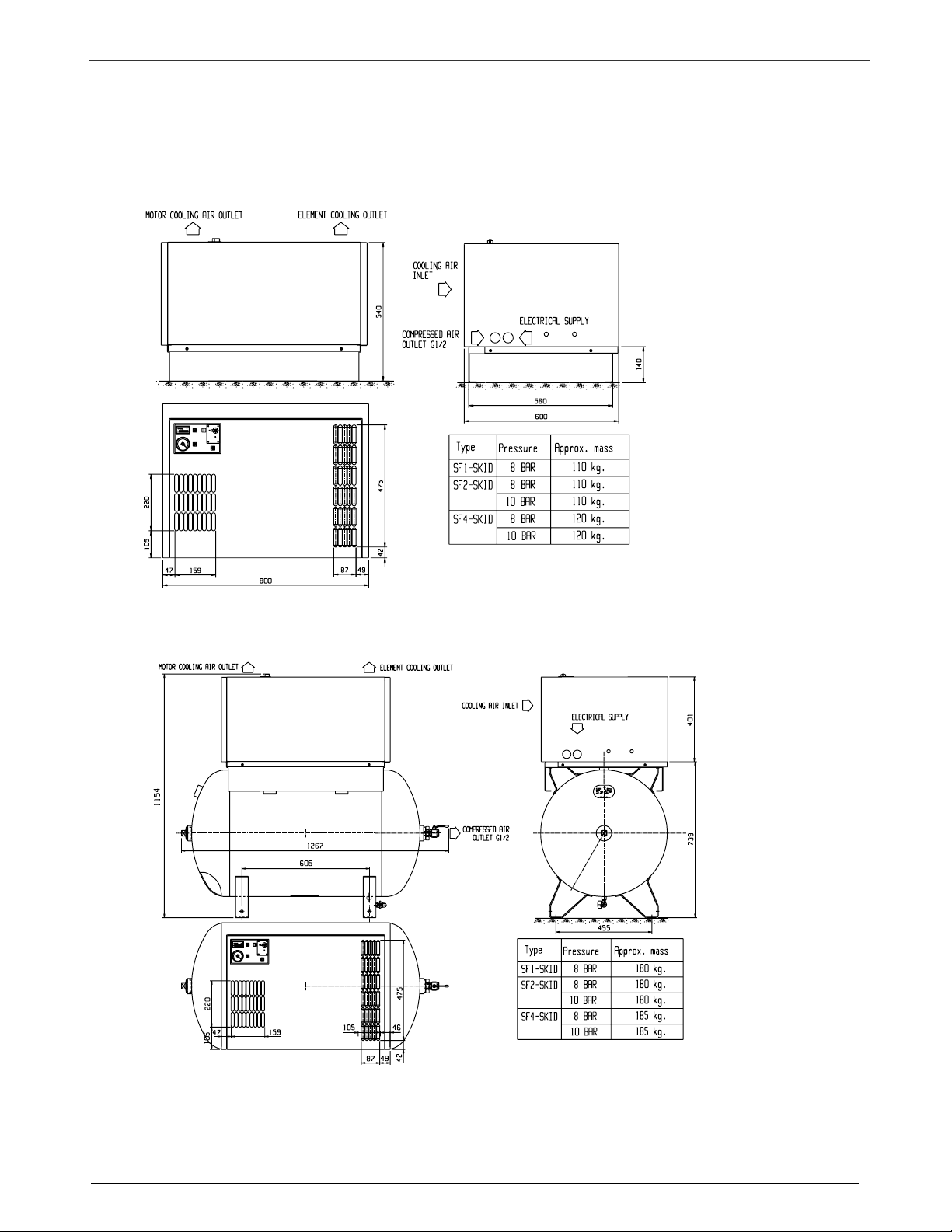
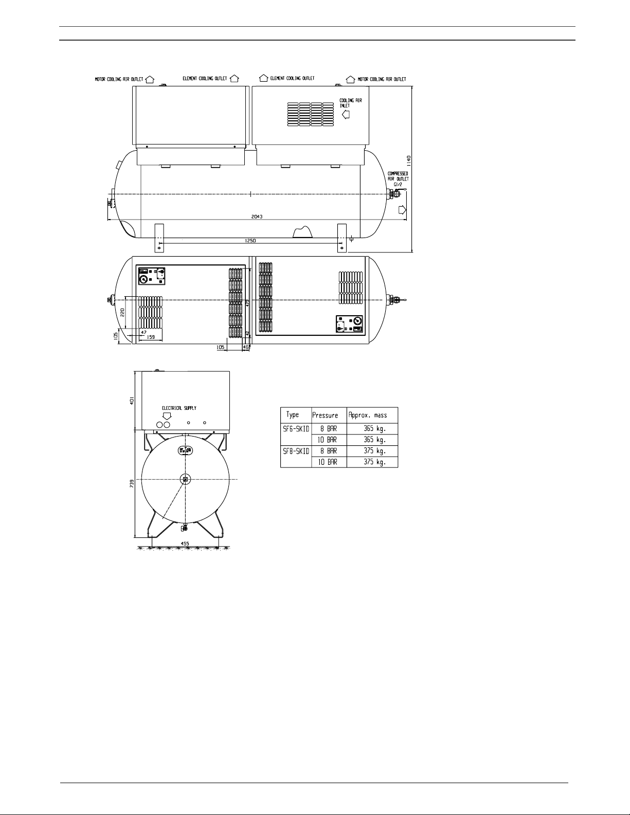
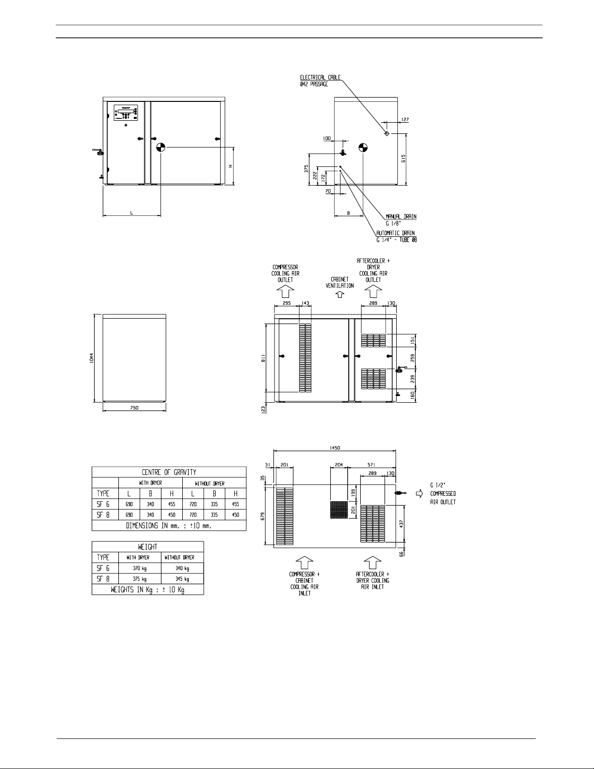
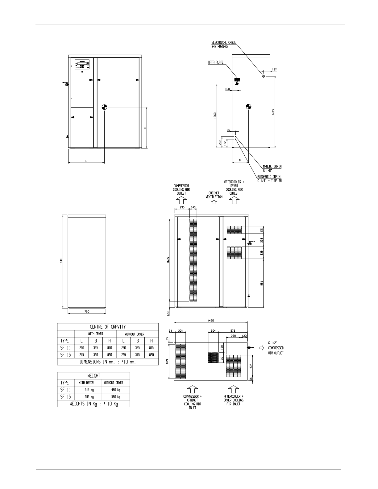
2.1 Dimension drawings (Figs. 2.1 up to 2.5)
9820 4052 00/1
55100D
(1)
(2)
(3)
(4)
(5)
(6)
(7)
(8)
Fig. 2.1 Dimension drawing, SF 1-4 Skid
9820 4053 00/1
55101D
(1)
(2)
(3)
(4)
(5)
(6)
(7)
(8)
Fig. 2.2 Dimension drawing, SF 1-4 Tank-mounted
Instruction book
2920 1521 00 18
9820 4054 00/1
55102D
(1)
(2)
(2)
(1)
(3)
(4)
(5)
(6)
(7) (8)
Fig. 2.3 Dimension drawing, SF 6-8 Twin
Text on Figs.2.1/2.3
1 Motor cooling air outlet 5 Electrical supply
2 Element cooling outlet 6 Type
3 Cooling air inlet 7 Pressure
4 Compressed air outlet 8 Mass, approx.
Instruction book
2920 1521 00 19
(1)
(2)
(3)
(4)
(5)
(6)
(7)
(8)
(9)
(10)
(11)
(8)
(9)
(12)
(13)
(14)
(15)
9820 4027 00
55098D
Fig. 2.4 Dimension drawing, SF 6-8 Multi
Instruction book
2920 1521 00 20
9820 4026 00
55099D
(1)
(16)
(2)
(3)
(4)
(5)
(6)
(7)
(8)
(9)
(10)
(11)
(8)
(9)
(12)
(13)
(14)
(15)
Fig. 2.5 Dimension drawing, SF 11-15 Multi

Instruction book
2920 1521 00 21
Text on Figs. 2.4/2.5
(1) Electric cable
(2) Manual drain
(3) Automatic drain
(4) Compressor cooling air outlet
(5) Bodywork ventilation
(6) Aftercooler and dryer cooling air outlet
(7) Centre of gravity
(8) With dryer
(9) Without dryer
(10) Dimensions +/- 10 mm
(11) Weight
(12) Weight +/- 10 kg
(13) Compressor and bodywork cooling air inlet
(14) Aftercooler and dryer cooling air inlet
(15) Compressed air outlet
(16) Data plate
 Loading...