How it Works
Log In / Sign Up
Buy Points
How it Works
FAQ
Contact Us
Questions and Suggestions
Users
Asus
Loading...
R
RS162-E4/RX4
5
RS163
RS163-E4
RS163-E4/RX4
RS200-E9-PS2
2
RS200-E9-PS2-F
2
RS260-E3RS8
3
RS260-E4/RX8
3
RS300-E10-PS4
4
RS300-E10-RS4
4
RS300-E6
2
RS300-E6/PS2
3
RS300-E6PS4
2
RS300-E7-PS4
7
RS300-E7/RS4
5
RS300-E8-PS4
4
RS300-E8-RS4
5
RS300-E9-PS4
3
RS300-E9-RS4
4
RS300-H8-PS12
2
RS320Q-E7/RS12
RS400-E8-PS2
2
RS400-E8-PS2-F
2
RS500A-E10-PS4
4
RS500A-E10-RS12U
5
RS500A-E10-RS4
2
RS500A-E6PS4
4
RS500A-E9
RS500A-E9-PS4
2
RS500A-E9-RS4
3
RS500A-E9-RS4-U
3
RS500A-S6/PS4
2
RS500A-X6PS4
2
RS500-E6-EPS4
2
RS500-E6/EPS4 ASWM ENTERPRISE
RS500-E6/PS4
5
RS500-E6-PS8
2
RS500-E7/PS4
2
RS500-E8-PS4
3
RS500-E8-RS4
3
RS500-E8-RS4 V2
RS500-E9
RS500-E9-PS4
4
RS500-E9-RS4
4
RS500-E9-RS4-U
4
RS520-E6/ERS8
2
RS520-E6RS8
4
RS520-E8-RS12-E
8
RS520-E8-RS8
8
RS520-E8-RS8 V2
RS520-E9
RS520-E9-RS12-E
4
RS520-E9-RS8
4
RS520-X5/PS8
3
RS540-E8-RS36-ECP
3
RS540-E9-RS36-E
3
RS620SA-E10-RS12
RS700A-E11-RS12U
RS700A-E9-RS12
4
RS700A-E9-RS12V2
3
RS700A-E9-RS4
4
RS700A-E9-RS4V2
3
RS700DA-E6 PS4
2
RS700D-E6PS8
4
RS700D-E6/PS8 ASWM ENTERPRISE
RS700-E6/ERS4
3
RS700-E6/ERS4 ASWM ENTERPRISE
RS700-E6RS4
3
RS700-E7-RS12
RS700-E7/RS4
6
RS700-E7/RS4-C
4
RS700-E7/RS8
6
RS700-E8-RS4
9
RS700-E8-RS4 V2
2
RS700-E8-RS8
8
RS700-E9-RS12
5
RS700-E9-RS4
5
RS700-X7/PS4
5
RS702D-E6PS8
RS704DA-E6/PS4
2
RS704D-E6/PS8
2
RS720A-E11-RS24U
RS720A-E9-RS12V2
3
RS720A-E9-RS24-E
2
RS720A-E9-RS24V2
2
RS720-E6RS12
2
RS720-E6/RS12 ASWM ENTERPRISE
RS720-E7/RS12
3
RS720-E7-RS12-E
6
RS720-E7-RS24-EG
2
RS720-E8-RS12-X
RS720-E8-RS24-E
2
RS720-E8-RS24-ECP
3
RS720-E9-RS12-E
4
RS720-E9-RS24-E
3
RS720-E9-RS24-U
3
RS720-E9-RS8
4
RS720-E9-RS8-G
4
RS720Q-E6 RS12
RS720Q-E6/RS12 ASWM ENTERPRISE
Loading...
Loading...
Nothing found
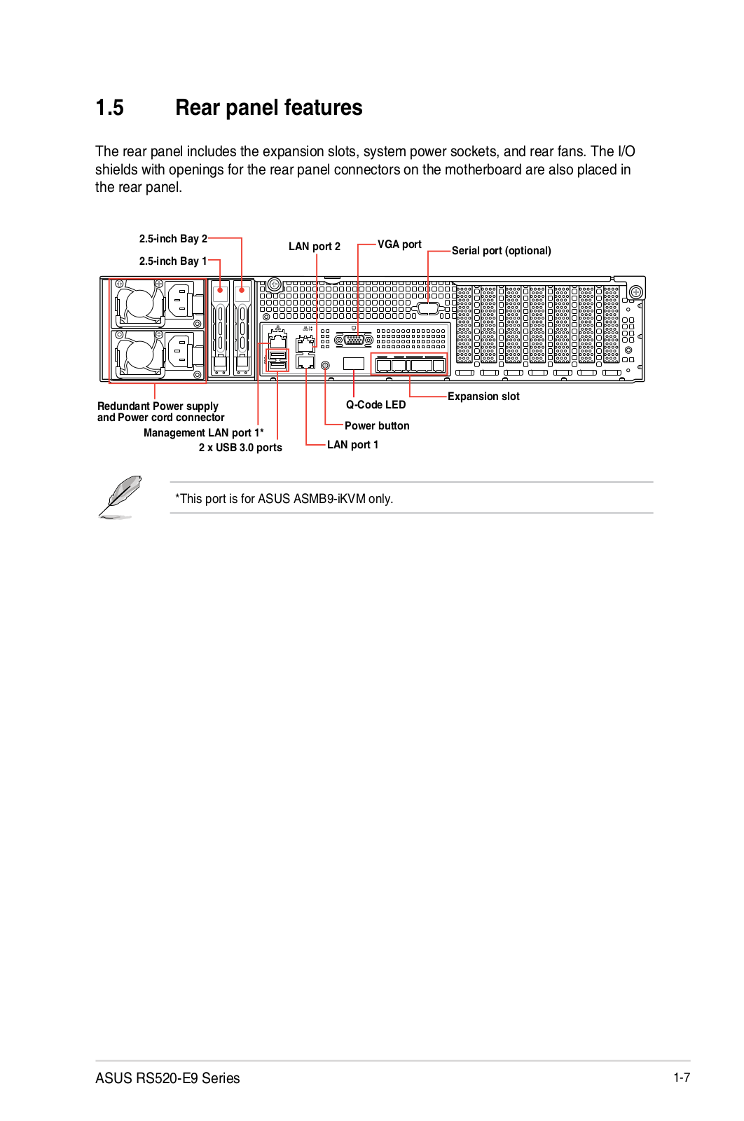
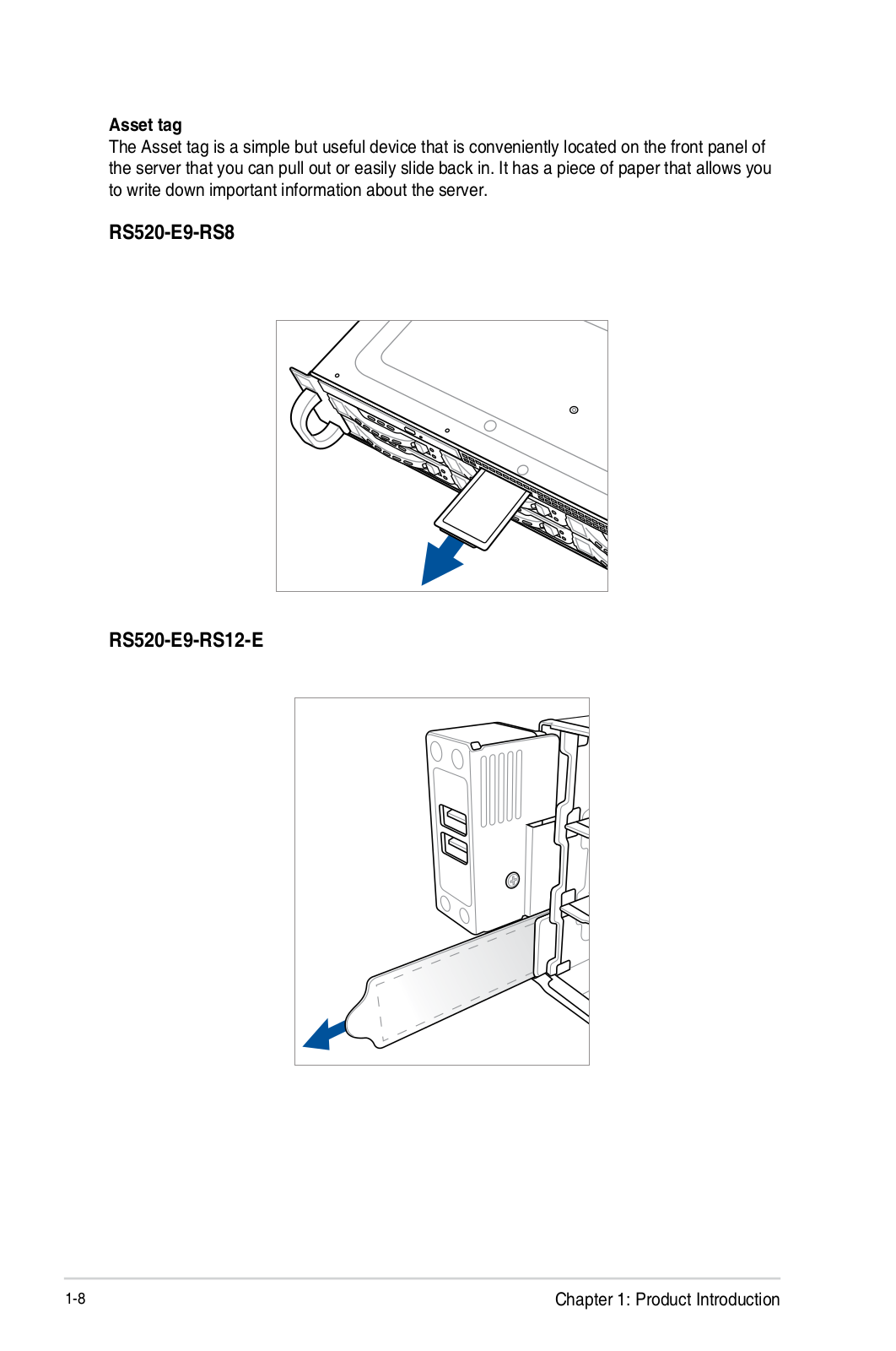
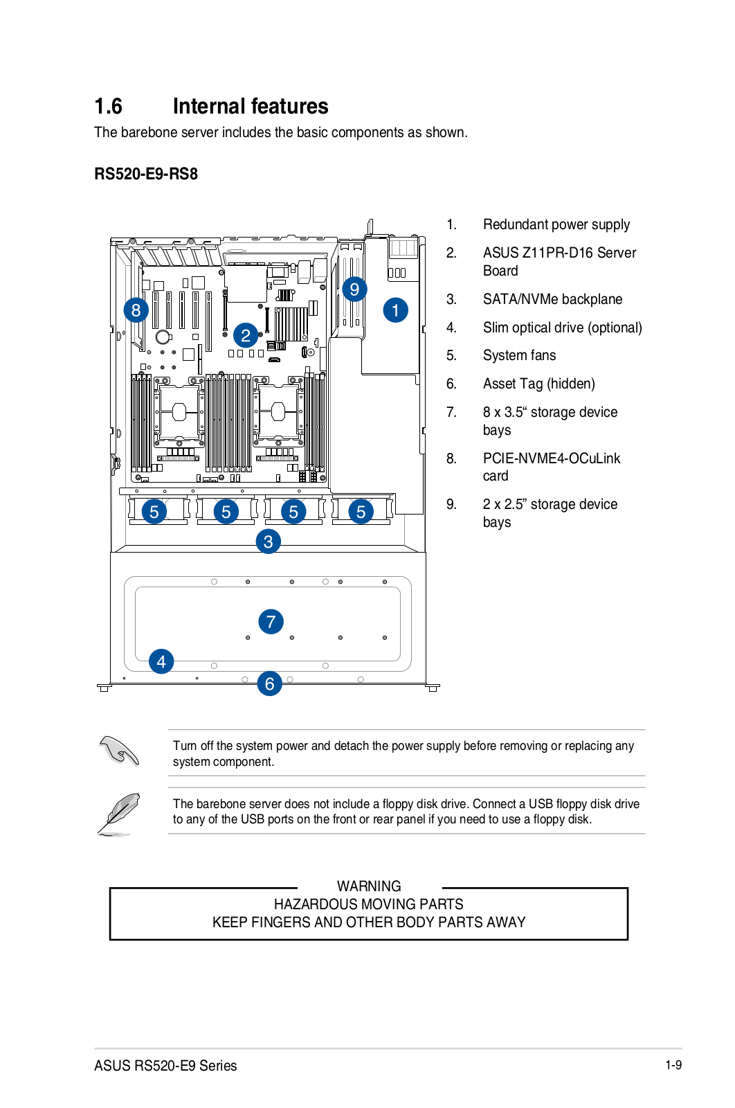
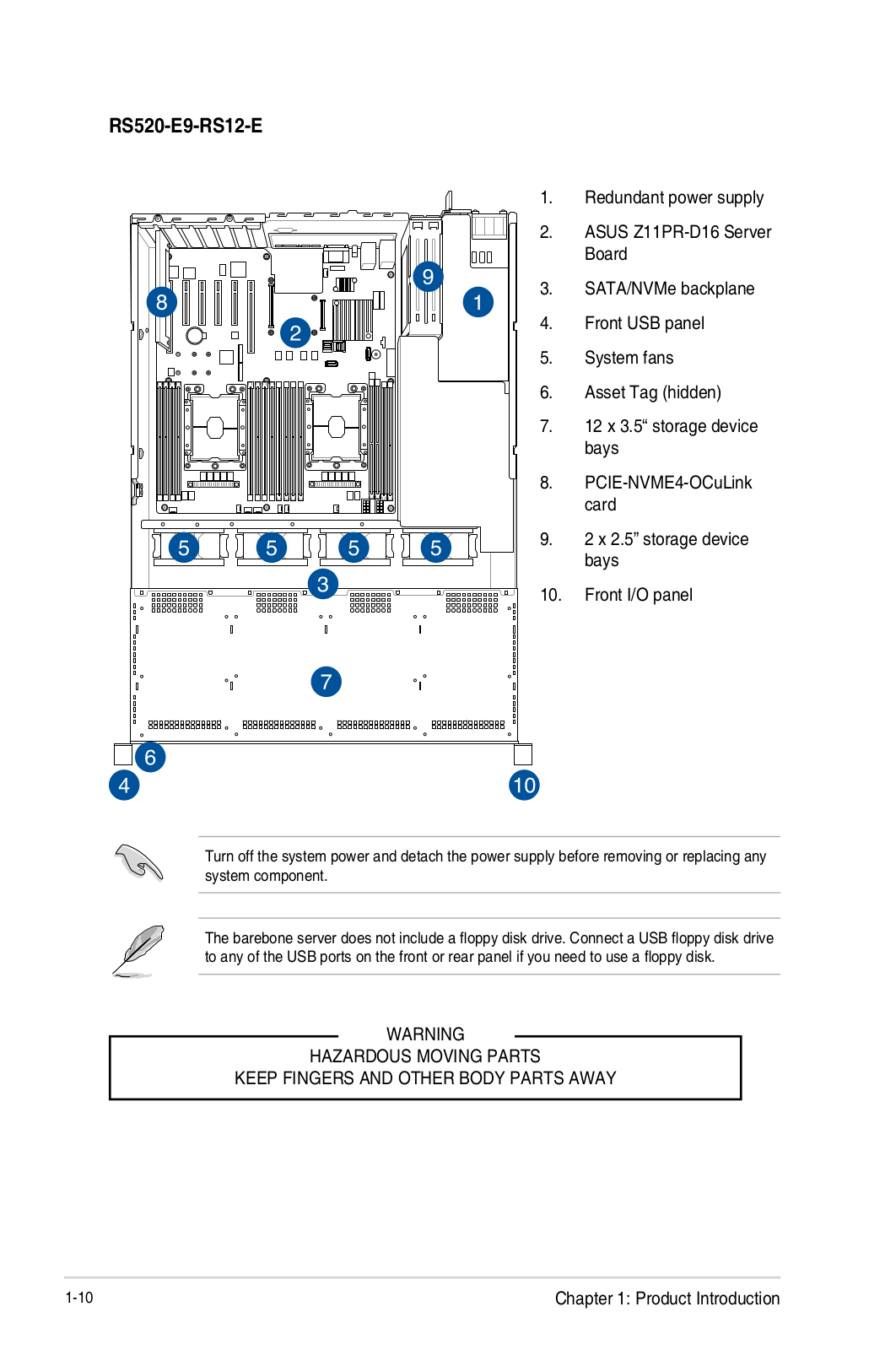
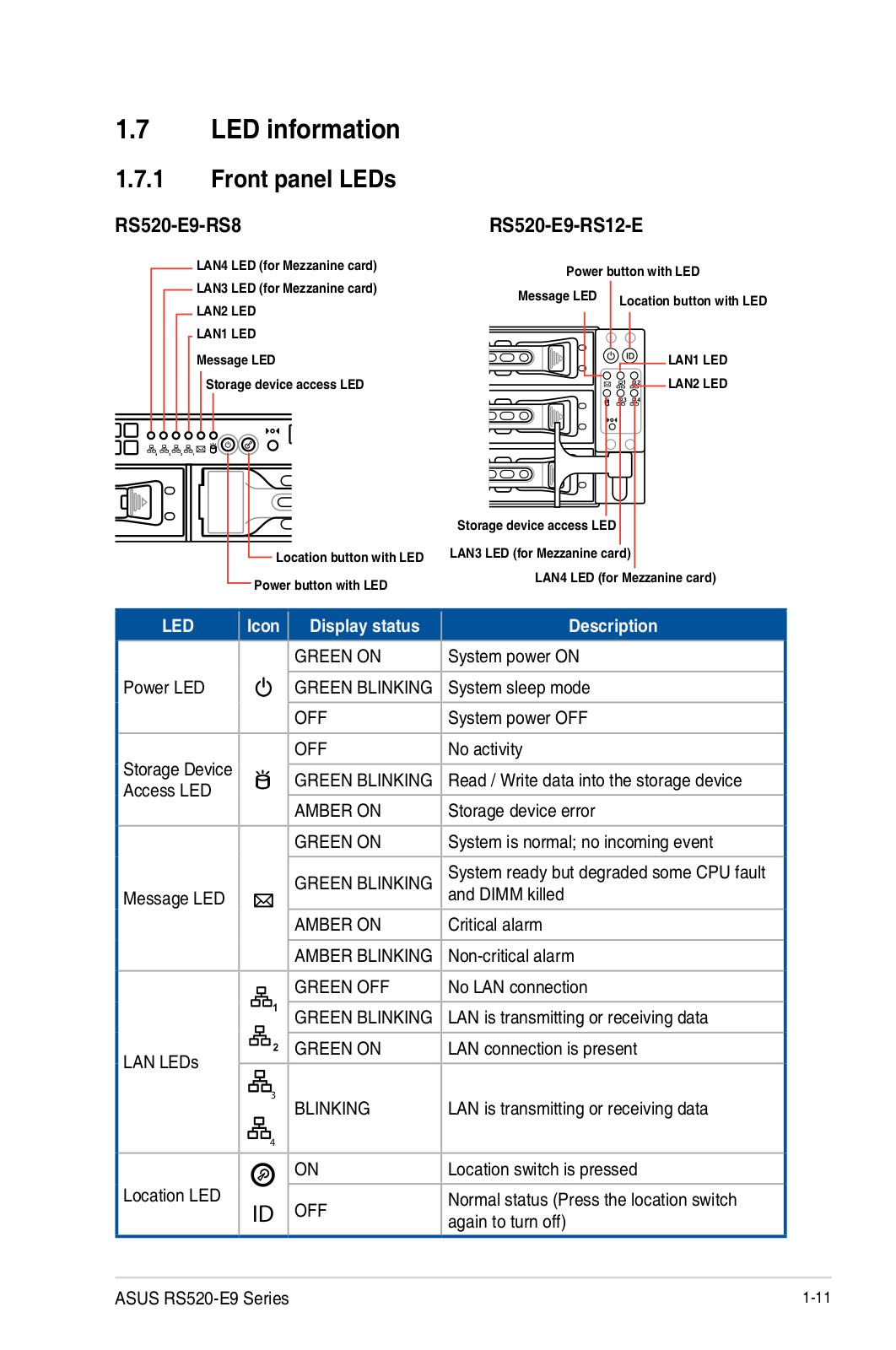
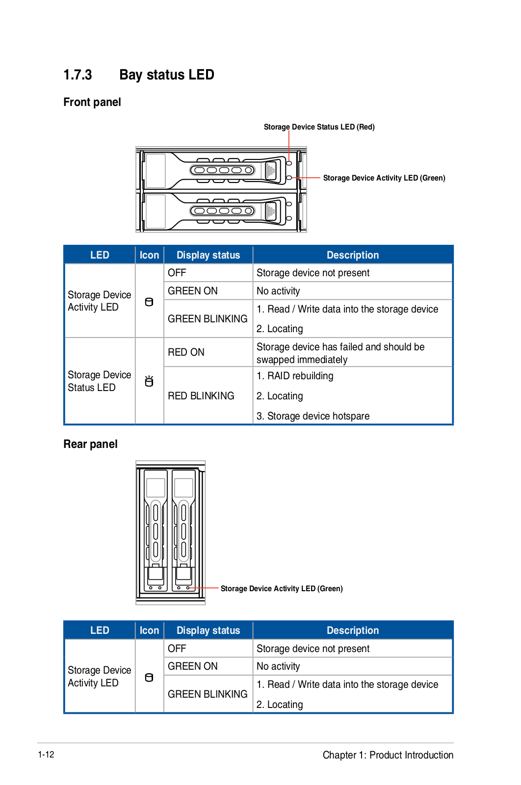
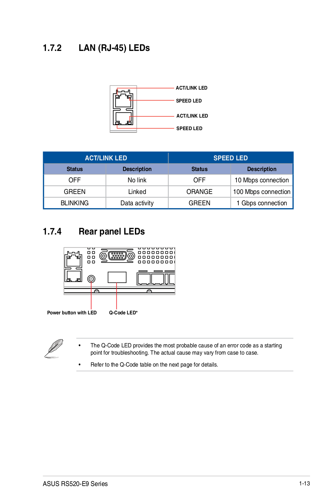
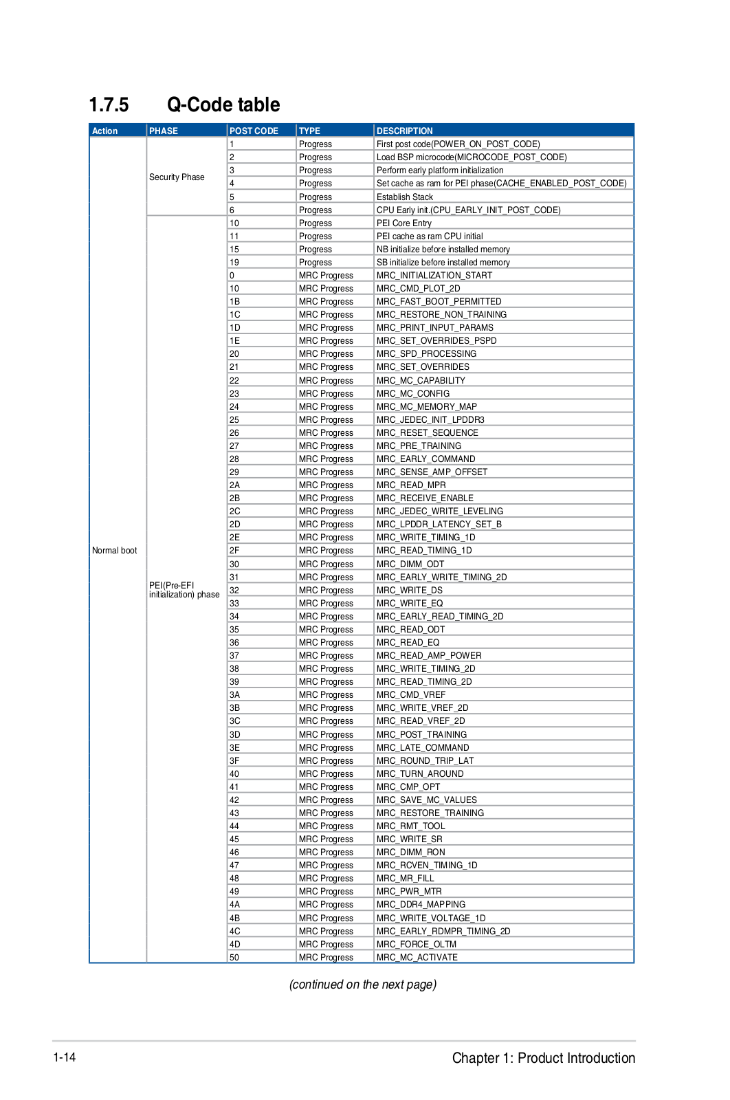
RS520-E9
User Manual
174 pgs
18.24 Mb
0
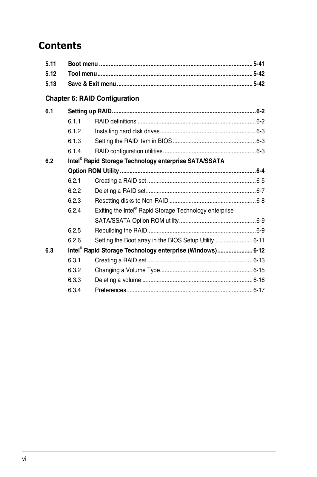
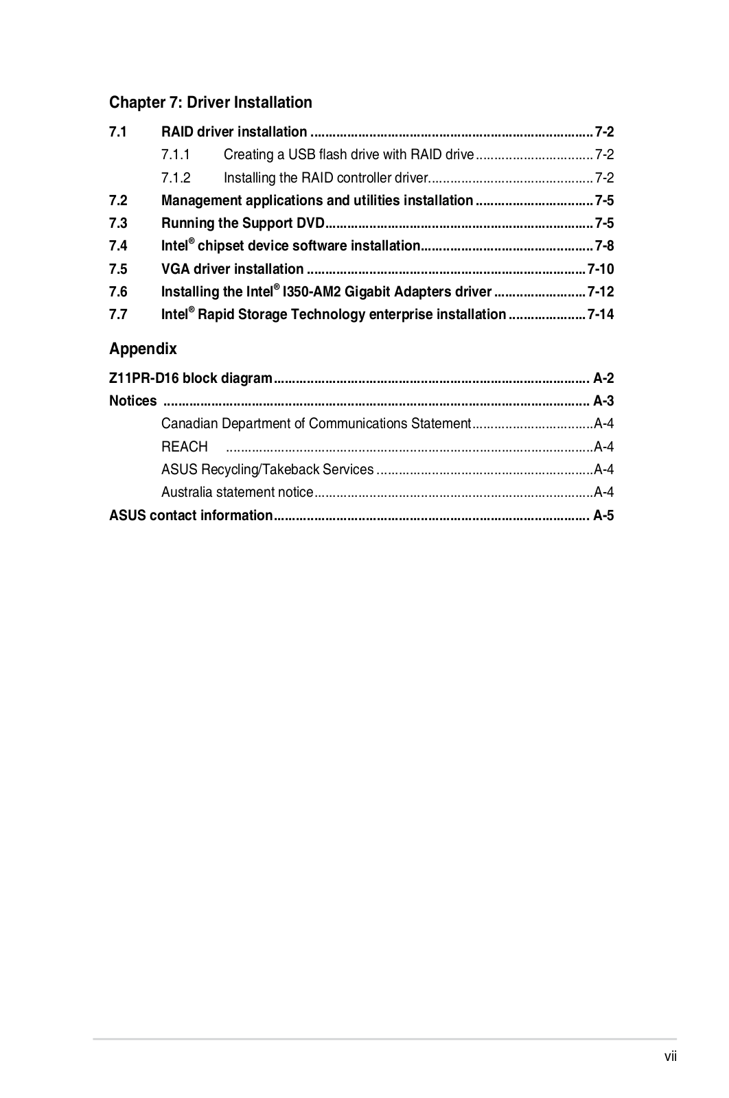
Table of contents
Loading...
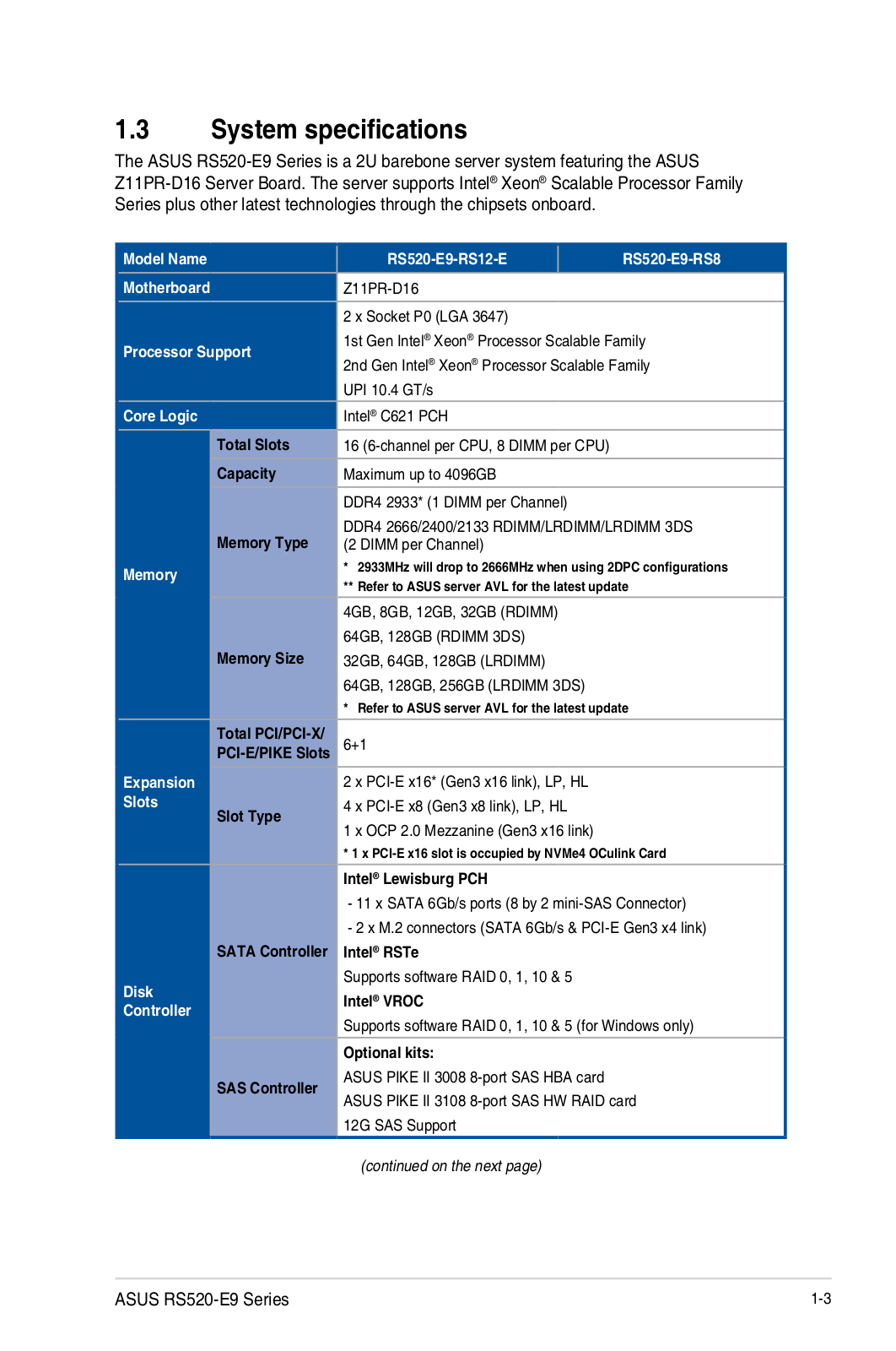
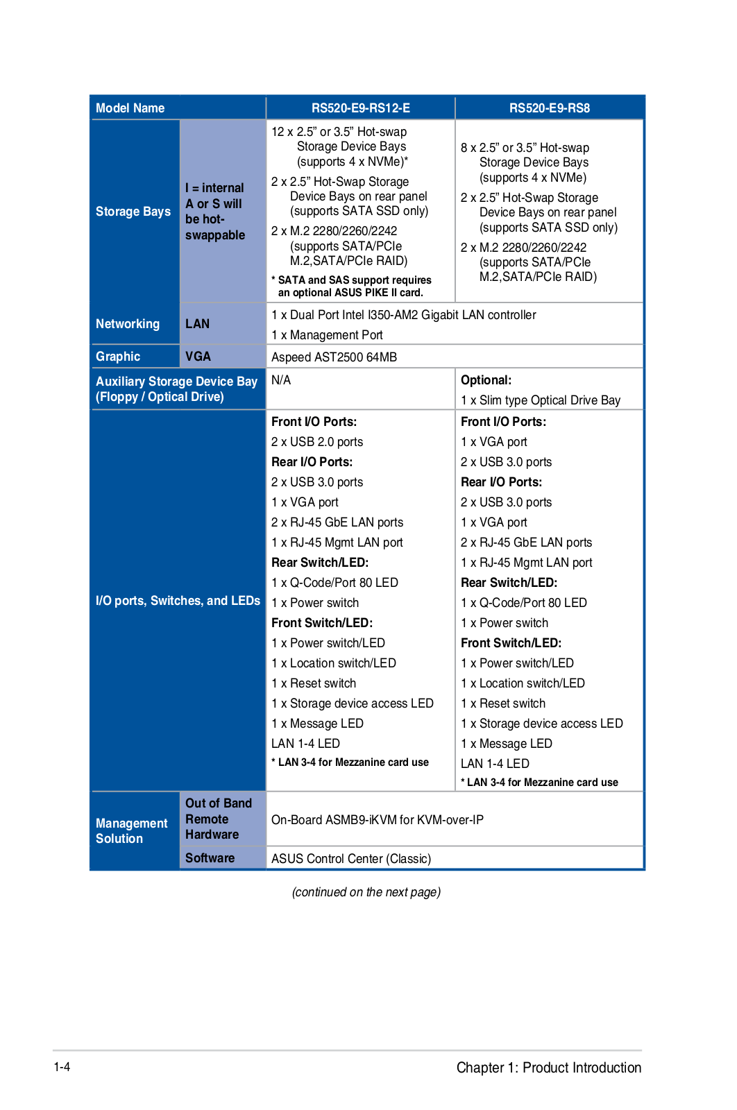
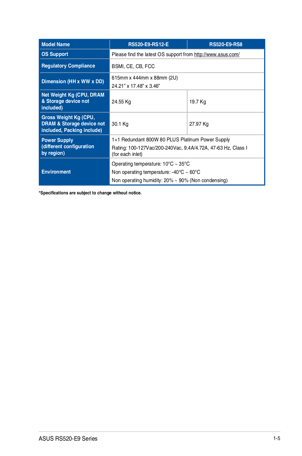
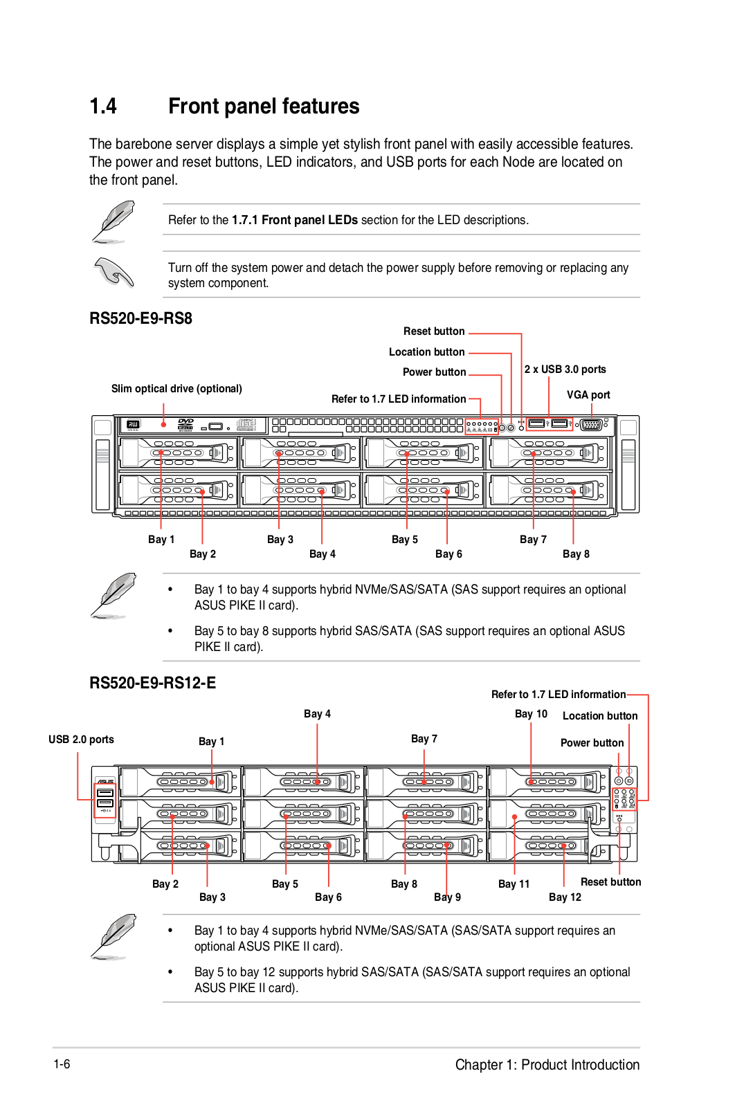
Asus RS520-E9 User Manual
...
Asus User Manual
Download
Specifications and Main Features
Frequently Asked Questions
User Manual
Download
Loading...
+
hidden pages
Unhide
You need points to download manuals.
1 point = 1 manual.
You can buy points or you can get point for every manual you upload.
Buy points
Upload your manuals
 Loading...