

Page 1
RS500A-E6/PS4
1U Rackmount Server
User Guide
Page 2

E5894
First Edition V1
June 2010
Copyright © 2010 ASUSTeK COMPUTER INC. All Rights Reserved.
No part of this manual, including the products and software described in it, may be reproduced, transmitted,
transcribed, stored in a retrieval system, or translated into any language in any form or by any means,
except documentation kept by the purchaser for backup purposes, without the express written permission
of ASUSTeK COMPUTER INC. (“ASUS”).
ASUS provides this manual “as is” without warranty of any kind, either express or implied, including but not
limited to the implied warranties or conditions of merchantability or tness for a particular purpose. In no
event shall ASUS, its directors, ofcers, employees, or agents be liable for any indirect, special, incidental,
or consequential damages (including damages for loss of prots, loss of business, loss of use or data,
interruption of business and the like), even if ASUS has been advised of the possibility of such damages
arising from any defect or error in this manual or product.
Specications and information contained in this manual ae furnished for informational use only, and are
subject to change at any time without notice, and should not be construed as a commitment by ASUS.
ASUS assumes no responsibility or liability for any errors or inaccuracies that may appear in this manual,
including the products and software described in it.
Product warranty or service will not be extended if: (1) the product is repaired, modied or altered, unless
such repair, modication of alteration is authorized in writing by ASUS; or (2) the serial number of the
product is defaced or missing.
Products and corporate names appearing in this manual may or may not be registered trademarks or
copyrights of their respective companies, and are used only for identication or explanation and to the
owners’ benet, without intent to infringe.
ii
Page 3

Contents
Contents ...................................................................................................... iii
Notices ......................................................................................................... vi
Safety information ..................................................................................... vii
About this guide ....................................................................................... viii
Chapter 1: Product introduction
1.1 System package contents ........................................................... 1-2
1.2 Serial number label ......................................................................
1.3 Systemspecications .................................................................
1.4 Front panel features .....................................................................
1.5 Rear panel features ......................................................................
1.6 Internal features ...........................................................................
1.7 LED information ...........................................................................
1.7.1 Front panel LEDs ............................................................
1.7.2 LAN (RJ-45) LEDs ..........................................................
1.7.3 HDD status LED ..............................................................
Chapter 2: Hardware setup
2.1 Chassis cover ............................................................................... 2-2
2.2 Central Processing Unit (CPU) ...................................................
2.2.1 Installing the CPU ...........................................................
2.2.2 Installing the CPU heatsink and airduct ..........................
2.3 System memory ...........................................................................
2.3.1 Overview .........................................................................
2.3.2 Memory Congurations ...................................................
2.3.3 Installing a DIMM ............................................................
2.3.4 Removing a DIMM ..........................................................
2.4 Hard disk drives .........................................................................
2.5 Expansion slot ............................................................................
2.5.1 Installing an expansion card to the riser card bracket ...
2.5.2 Conguring an expansion card .....................................
2.6 Cable connections .....................................................................
2.7 SATAII/SAS backplane cabling .................................................
2.8 Removable/optional components .............................................
2.8.1 System fans ..................................................................
1-2
1-3
1-5
1-5
1-6
1-7
1-7
1-7
1-8
2-3
2-3
2-6
2-7
2-7
2-7
2-9
2-9
2-10
2-12
2-12
2-14
2-15
2-16
2-17
2-17
iii
Page 4

Contents
2.8.2 Installing ASUS PIKE RAID card (optional) .................. 2-18
2.8.3 Installing ASMB4 series management board (optional) ...
Chapter 3: Installation options
3.1 Installing friction rail kit items .................................................... 3-2
3.1.1 Attaching the xing latches to the server ........................
3.1.2 Attaching the rack rails ....................................................
3.1.3 Mounting the server to the rack ......................................
3.2 Installing optional ball-bearing rail kit items ............................
3.2.1 Attaching the rails to the server ......................................
3.2.2 Attaching the rack rails ....................................................
3.2.3 Mounting the server to the rack ......................................
Chapter 4: Motherboard information
4.1 Motherboard layouts .................................................................... 4-2
4.2 Jumpers ........................................................................................
4.3 Internal connectors ......................................................................
Chapter 5: BIOS setup
5.1 Managing and updating your BIOS ............................................ 5-2
5.1.1 ASUS EZ Flash 2 utility ...................................................
5.1.2 BUPDATER utility
5.1.3 ASUS CrashFree BIOS 3 utility ......................................
5.2 BIOS setup program ....................................................................
5.2.1 BIOS menu screen ..........................................................
5.2.2 Menu bar .........................................................................
5.2.3 Navigation keys ...............................................................
5.2.4 Menu items .....................................................................
5.2.5 Submenu items ...............................................................
5.2.6 Conguration elds .........................................................
5.2.7 Pop-up window ...............................................................
5.2.8 Scroll bar .........................................................................
5.2.9 General help ...................................................................
5.3 Main menu ....................................................................................
5.3.1 System Time ...................................................................
5.3.2 System Date ...................................................................
............................................................ 5-3
2-21
3-2
3-3
3-4
3-5
3-5
3-6
3-7
4-4
4-8
5-2
5-5
5-6
5-7
5-7
5-7
5-8
5-8
5-8
5-8
5-8
5-8
5-9
5-9
5-9
iv
Page 5

Contents
5.3.3 SATA1–6 ....................................................................... 5-10
5.3.4 Storage Conguration ....................................................
5.3.5 System Information .......................................................
5.4 Advanced menu .........................................................................
5.4.1 CPU Conguration ........................................................
5.4.2 Chipset Conguration ...................................................
5.4.3 Onboard Devices Conguration ....................................
5.4.4 USB Conguration ........................................................
5.4.5 PCIPnP .........................................................................
5.5 Server menu ...............................................................................
5.6 Power menu ................................................................................
5.6.1 Suspend Mode ..............................................................
5.6.2 Repost Video on S3 Resume ........................................
5.6.3 ACPI 2.0 Support ..........................................................
5.6.4 ACPI APIC support .......................................................
5.6.5 APM Conguration ........................................................
5.6.6 Hardware Monitor .........................................................
5.7 Boot menu ..................................................................................
5.7.1 Boot Device Priority ......................................................
5.7.2 Hard Disk Drives; CDROM Drives ................................
5.7.3 Boot Settings Conguration ..........................................
5.7.4 Security .........................................................................
5.8 Tools menu .................................................................................
5.8.1 ASUS EZ Flash 2 ..........................................................
5.9 Exit menu ....................................................................................
5-11
5-12
5-14
5-14
5-16
5-25
5-26
5-27
5-28
5-30
5-30
5-30
5-30
5-30
5-31
5-32
5-34
5-34
5-34
5-35
5-36
5-38
5-38
5-39
Chapter 6: Driver installation
6.1 LAN driver installation ................................................................. 6-2
6.2 Display driver installation ...........................................................
6.3 ATI SM Bus controller driver installation ...................................
6.4 Management applications and utilities installation ................
6.4.1 Running the support DVD .............................................
6.4.2 Drivers menu .................................................................
6.4.3 Utilities menu .................................................................
6.4.4 Make disk menu .............................................................
6.4.5 Contact information ........................................................
6-6
6-9
6-10
6-10
6-10
6-11
6-11
6-11
v
Page 6
Notices
Federal Communications Commission Statement
This device complies with Part 15 of the FCC Rules. Operation is subject to the
following two conditions:
• This device may not cause harmful interference, and
• This device must accept any interference received including interference that
may cause undesired operation.
This equipment has been tested and found to comply with the limits for a Class B
digital device, pursuant to Part 15 of the FCC Rules. These limits are designed to
provide reasonable protection against harmful interference in a residential installation.
This equipment generates, uses and can radiate radio frequency energy and, if
not installed and used in accordance with manufacturer’s instructions, may cause
harmful interference to radio communications. However, there is no guarantee that
interference will not occur in a particular installation. If this equipment does cause
harmful interference to radio or television reception, which can be determined by turning
the equipment off and on, the user is encouraged to try to correct the interference by
one or more of the following measures:
• Reorient or relocate the receiving antenna.
• Increase the separation between the equipment and receiver.
• Connect the equipment to an outlet on a circuit different from that to which the
receiver is connected.
• Consult the dealer or an experienced radio/TV technician for help.
WARNING! The use of shielded cables for connection of the monitor to the
graphics card is required to assure compliance with FCC regulations. Changes
or modications to this unit not expressly approved by the party responsible for
compliance could void the user’s authority to operate this equipment.
Canadian Department of Communications Statement
This digital apparatus does not exceed the Class B limits for radio noise emissions
from digital apparatus set out in the Radio Interference Regulations of the Canadian
Department of Communications.
This Class B digital apparatus complies with Canadian ICES-003.
DO NOT throw the motherboard in municipal waste. This product has been designed to
enable proper reuse of parts and recycling. This symbol of the crossed out wheeled bin
indicates that the product (electrical and electronic equipment) should not be placed in
municipal waste. Check local regulations for disposal of electronic products.
DO NOT throw the mercury-containing button cell battery in municipal waste. This
symbol of the crossed out wheeled bin indicates that the battery should not be
placed in municipal waste.
vi
Page 7

Safety information
Electrical Safety
• Before installing or removing signal cables, ensure that the power cables for the
system unit and all attached devices are unplugged.
• To prevent electrical shock hazard, disconnect the power cable from the electrical
outlet before relocating the system.
• When adding or removing any additional devices to or from the system, ensure
that the power cables for the devices are unplugged before the signal cables
are connected. If possible, disconnect all power cables from the existing system
before you add a device.
• If the power supply is broken, do not try to x it by yourself. Contact a qualied
service technician or your dealer.
Operation Safety
• Any mechanical operation on this server must be conducted by certied or
experienced engineers.
• Before operating the server, carefully read all the manuals included with the server
package.
• Before using the server, ensure all cables are correctly connected and the power
cables are not damaged. If any damage is detected, contact your dealer as soon
as possible.
• To avoid short circuits, keep paper clips, screws, and staples away from
connectors, slots, sockets and circuitry.
• Avoid dust, humidity, and temperature extremes. Place the server on a stable
surface.
This product is equipped with a three-wire power cable and plug for the user’s
safety. Use the power cable with a properly grounded electrical outlet to avoid
electrical shock.
Lithium-Ion Battery Warning
CAUTION! Danger of explosion if battery is incorrectly replaced. Replace
only with the same or equivalent type recommended by the manufacturer.
Dispose of used batteries according to the manufacturer’s instructions.
CD-ROM Drive Safety Warning
CLASS 1 LASER PRODUCT
Heavy System
CAUTION! This server system is heavy. Ask for assistance when moving or
carrying the system.
vii
Page 8

About this guide
Audience
This user guide is intended for system integrators, and experienced users with at
least basic knowledge of conguring a server.
Contents
This guide contains the following parts:
1. Chapter 1: Product introduction
This chapter describes the general features of the server, including sections
on front panel and rear panel specications.
2. Chapter 2: Hardware setup
This chapter lists the hardware setup procedures that you have to perform
when installing or removing system components.
3. Chapter 3: Installation options
This chapter describes how to install optional components into the barebone
server.
4. Chapter 4: Motherboard information
This chapter gives information about the motherboard that comes with the
server. This chapter includes the motherboard layout, jumper settings, and
connector locations.
5. Chapter 5: BIOS information
This chapter tells how to change system settings through the BIOS Setup
menus and describes the BIOS parameters.
6 Chapter 6: Driver installation
This chapter provides instructions for installing the necessary drivers for
different system components.
viii
Page 9

Conventions
To ensure that you perform certain tasks properly, take note of the following
symbols used throughout this manual.
DANGER/WARNING: Information to prevent injury to yourself when
trying to complete a task.
CAUTION: Information to prevent damage to the components when
trying to complete a task.
IMPORTANT: Instructions that you MUST follow to complete a task.
NOTE: Tips and additional information to help you complete a task.
Typography
Bold text
Italics
<Key> Keys enclosed in the less-than and greater-than
sign means that you must press the enclosed key.
Example: <Enter> means that you must press
the Enter or Return key.
<Key1+Key2+Key3> If you must press two or more keys simultaneously,
the key names are linked with a plus sign (+).
Example: <Ctrl+Alt+D>
Command
exactly as shown, then supply the required
item or value enclosed in brackets.
Example: At the DOS prompt, type the
command line:
Indicates a menu or an item to select.
Used to emphasize a word or a phrase.
Means that you must type the command
format A:/S
References
Refer to the following sources for additional information, and for product and
software updates.
1. ASUS Server Web-based Management (ASWM) user guide
This manual tells how to set up and use the proprietary ASUS server
management utility.
2. ASUS websites
The ASUS websites worldwide provide updated information for all ASUS
hardware and software products. Refer to the ASUS contact information.
ix
Page 10

x1-ASUS RS500A-E6/PS4
Page 11

Chapter 1
This chapter describes the general
features of the chassis kit. It includes
sections on front panel and rear panel
specications.
Product introduction
Page 12
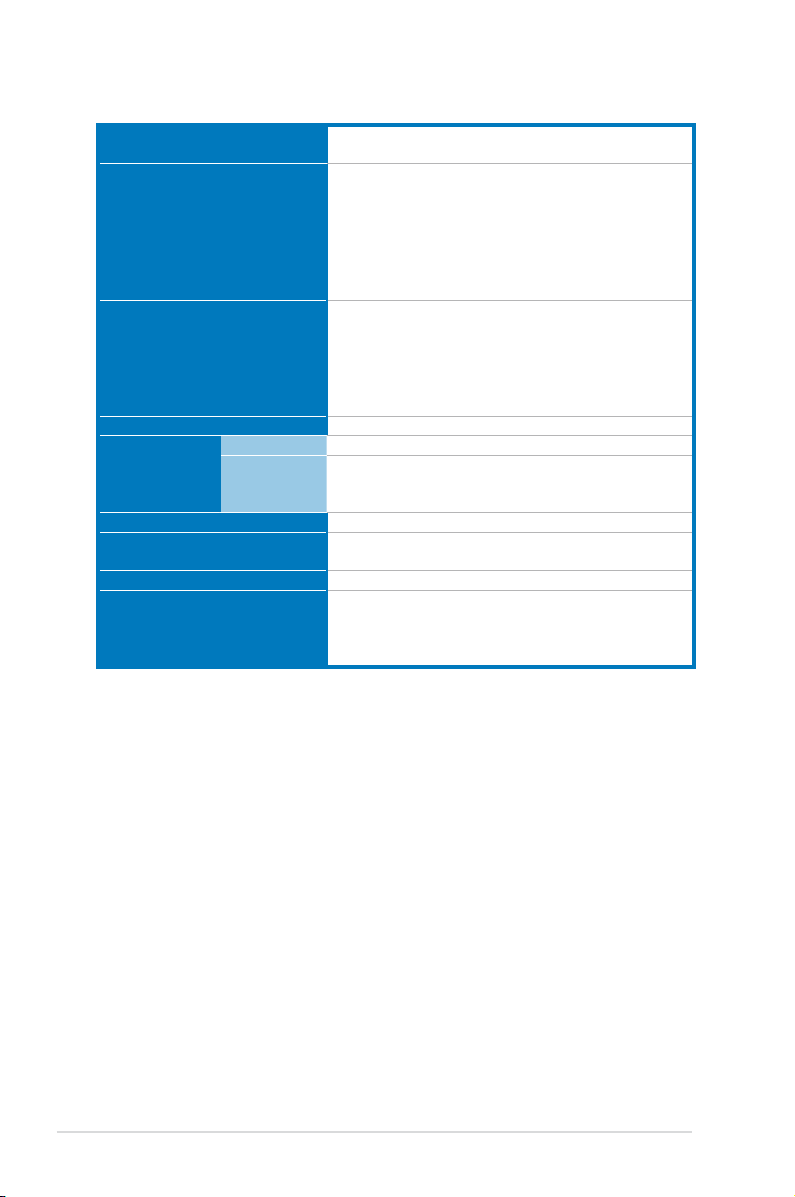
1.1 System package contents
Check your system package for the following items.
Model Name RS500A-E6/PS4
Chassis ASUS R10A 1U Rackmount Chassis
Motherboard ASUS KGNE-D16 Server Board
Component 1 x 500W 80+ Single Power Supply
Accessories 1 x RS500A-E6/PS4 User Guide
Optional Items 2 x CPU Heatsinks (varies by territories)
*ASUS System Web-based Management
4 x Hot-swap 3.5” HDD trays (varies by territories)
1 x SAS/SATAII HDD Backplane (BP4LX-R10A)
1 x PCI Riser Card (RE16L-R10)
1 x Front I/O Shield (FPB-AR14)
5 x System Fans (40 x 56mm)
1 x Air Duct
1 x ASUS ASWM 2.0 User Guide
1 x RS500A-E6/PS4 Support CD (including ASWM*)
1 x Bag of Screws
1 x AC Power Cable
1 x Friction Rail Kit
1 x Slim-type Optical Device
1 x ASMB4-iKVM Remote Management Card
1 x PIKE RAID Card
1 x Anti-virus CD
1 x Semi-ball Bearing Rail Kit
If any of the above items is damaged or missing, contact your retailer.
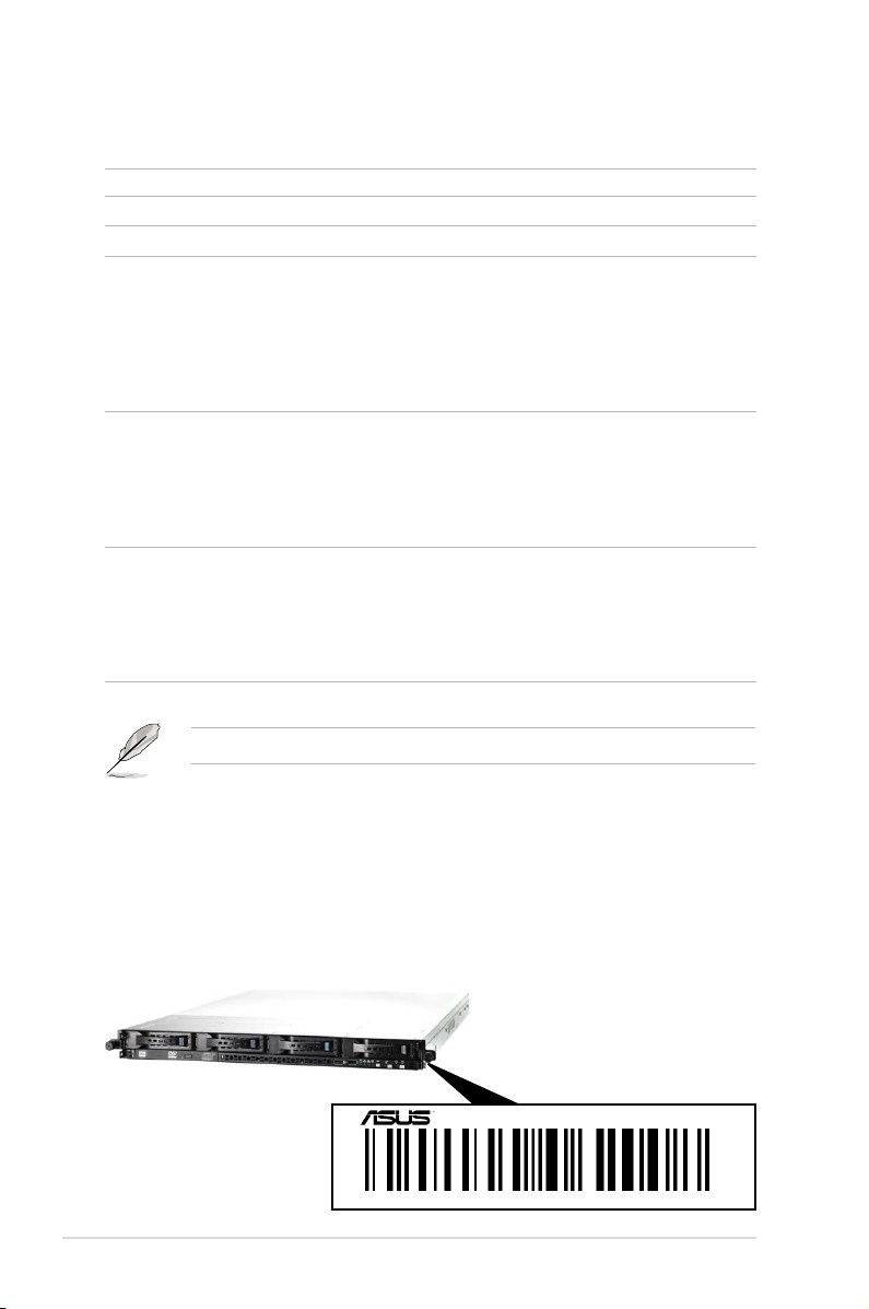
1.2 Serial number label
Before requesting support from the ASUS Technical Support team, you must
take note of the product’s serial number containing 12 characters such as
xxS0xxxxxxxx. See the gure below.
With the correct serial number of the product, ASUS Technical Support team
members can then offer a quicker and satisfying solution to your problems.
RS500A-E6/PS4
xxS0xxxxxxxx
Chapter 1: Product introduction1-2
Page 13
1.3 Systemspecications
The ASUS RS500A-E6/PS4 is a server featuring the ASUS KGNE-D16 server
board. The server supports AMD® LGA 1944 Opteron™ 6100 series processors
with HyperTransport™ technology, plus other latest technologies through the
chipsets onboard.
2 x Socket G34 (LGA 1944)
Processor Support / System Bus
Core Logic
Total Slots
Capacity
Memory
Expansion Slots
Storage
HDD Bays
Networking LAN
Graphic VGA
Memory Type
Memory Size
Total PCI/PCI-X /
PCI-E Slots
Slot Type
Additional Slot
SATA Controller
SAS Controller
I = Internal
A or S will be
hot-swappable
8/12 Core AMD® Opteron™ 6100 Series:
HyperTransport™ Technology 3.0,
6.4 GT/s per link (triple link)
Northbridge: AMD® SR5650
Southbridge: AMD® SP5100
16 (4-channel per CPU)
Maximum up to 256GB (RDIMM)
Maximum up to 64GB (UDIMM)
DDR3 800/1066/1333 UDIMM with ECC / non ECC
DDR3 800/1066/1333 RDIMM
1GB, 2GB, 4GB, 8GB, 16GB (RDIMM)
1GB, 2GB, 4GB (UDIMM)
1
Default Riser Card:
1 x PCI-E G2 x16 slot (G2 x16 link) (Full-Height/
Half-Length)
1 x PIKE Slot for Storage Enhancement
AMD® SP5100:
6 x SATA2 300MB/s ports
Optional:
ASUS PIKE 1064E 4-port SAS RAID card
ASUS PIKE 1078 8-port SAS HW RAID card
ASUS PIKE 2008 8-port SAS2 6G RAID card
ASUS PIKE 2008/IMR 8-port SAS2 6G RAID card
4 x Hot-Swap 3.5” SAS/SATA2 HDD Bays
2 x Intel® PCI-E GbE LAN (82574L)
1 x Mgmt LAN
Aspeed AST2050 8MB
(continued on the next page)
ASUS RS500A-E6/PS4 1-3
Page 14
Auxiliary Storage CD / DVD
1 x Slim-type Optical Device Bay
(Options: No Device / DVD-RW)
3 x RJ-45 ports (One for ASMB4-iKVM)
4 x USB 2.0 ports (Front x 2, Rear x 2)
1 x External Serial Port
Onboard I/O
1 x VGA port
1 x PS/2 keyboard port
1 x PS/2 mouse port
1 x Internal A Type USB port
Windows® Server 2008 R2
Windows® Server 2008 Enterprise 32/64-bit
OS Support
Windows® Server 2003 R2 Enterprise 32/64-bit
RedHat® Enterprise Linux AS5.0 32/64-bit
SuSE® Linux Enterprise Server 10 32/64-bit
(Subject to change without any notice)
Anti-virus Software
Software
Management
Solution
Out of Band
Remote
Optional CA® eTrust™ 7.1 anti-virus software
ASWM 2.0
Optional ASMB4-iKVM for KVM-over-IP support
Management
Dimension (HH x WW x DD)
Net Weight Kg (CPU, DRAM &
HDD not inclu ded)
Power Supply
615mm x 444mm x 43.6mm (1U)
15 Kg
500W 80+ Single Power Supply (Gold Level)
Operation temperature: 10°C — 35°C /
Environment
Non operation temperature: -40°C — 70°C
Non operation humidity: 20% — 90%
(Non-condensing)
*Specicationsaresubjecttochangewithoutnotice.
Chapter 1: Product introduction1-4
Page 15
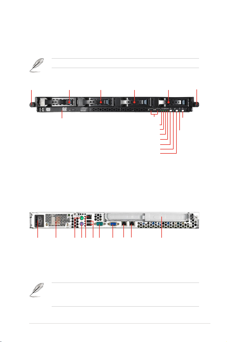
1.4 Front panel features
The barebone server displays a simple yet stylish front panel with easily accessible
features. The power and reset buttons, LED indicators, optical drive, and two USB
ports are located on the front panel.
Refer to section 1.7.1 Front panel LEDs for the LED descriptions.
Rack screw
HDD 1 HDD 2 HDD 3 HDD 4
Optical drive
USB ports
HDD Access LED
LAN2 LED
LAN1 LED
Message LED
Reset button
Location LED
Location switch
Rack screw
Power
button
Power
LED
1.5 Rear panel features
The rear panel includes the expansion slots, system power socket, and rear fans.
The middle part includes the I/O shield with openings for the rear panel connectors
on the motherboard.
Power cord connector
Power supply fan
PS/2 mouse port
Serial port
USB ports
LAN port 3*
PS/2 keyboard port
VGA port
LAN port 2
LAN port 1
Expansion slot
• The ports for the PS/2 keyboard, PS/2 mouse, USB, VGA, and Gigabit LAN
do not appear on the rear panel if motherboard is not present.
• *The port is for ASUS ASMB4-iKVM controller card only.
ASUS RS500A-E6/PS4 1-5
Page 16
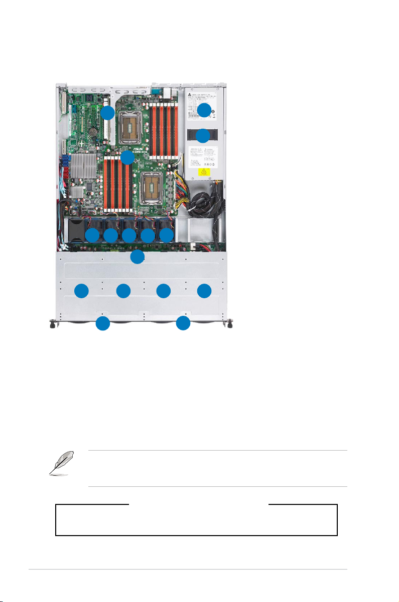
1.6 Internal features
The barebone server includes the basic components as shown.
1. PCI Express G2 x16 slot
Riser Card (G2 x16 link)
1
4
2
3
9
7
8
5
6
10
14131211
16
15
2. Power fans
3. ASUS KGNE-D16
server board
4. Power supply
5. System fan 1* - Connects
to CPU_FAN2 connector
6. System fan 2* - Connects
to FRNT_FAN1
connector
7. System fan 3* - Connects
to FRNT_FAN2
connector
8. System fan 4* - Connects
to FRNT_FAN3
connector
9. System fan 5* - Connects
to FRNT_FAN4
connector
10. SAS/SATAII backplane
11. Hot-Swap HDD tray 1 - Connects to SATA1 port (Port 0)
12. Hot-Swap HDD tray 2 - Connects to SATA2 port (Port 1)
13. Hot-Swap HDD tray 3 - Connects to SATA3 port (Port 2)
14. Hot-Swap HDD tray 4 - Connects to SATA4 port (Port 3)
15. Front I/O board (hidden)
16. Slim-type optical drive
The barebone server does not include a oppy disk drive. Connect a USB oppy
disk drive to any of the USB ports on the front or rear panel if you need to use a
oppy disk.
*WARNING
HAZARDOUS MOVING PARTS
KEEP FINGERS AND OTHER BODY PARTS AWAY
Chapter 1: Product introduction1-6
Page 17
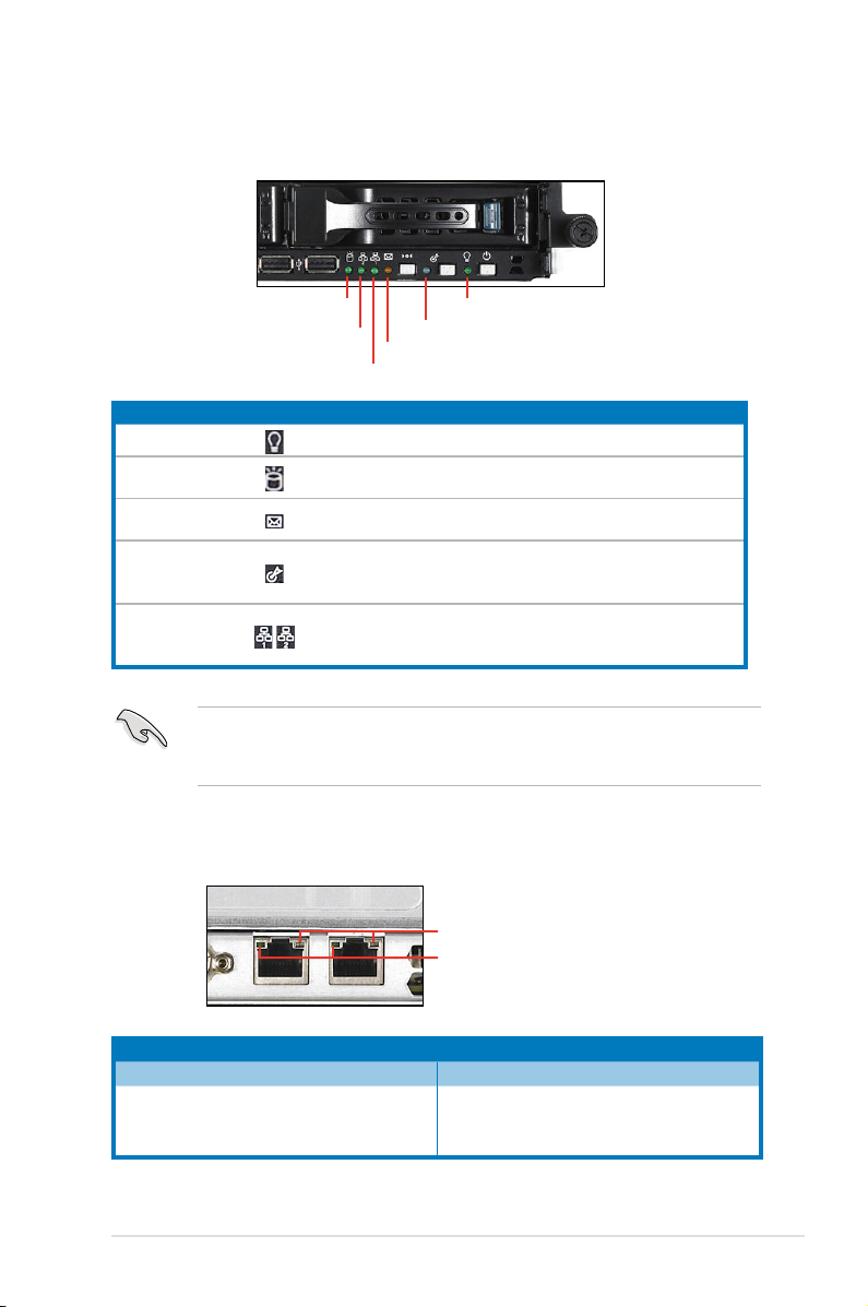
1.7 LED information
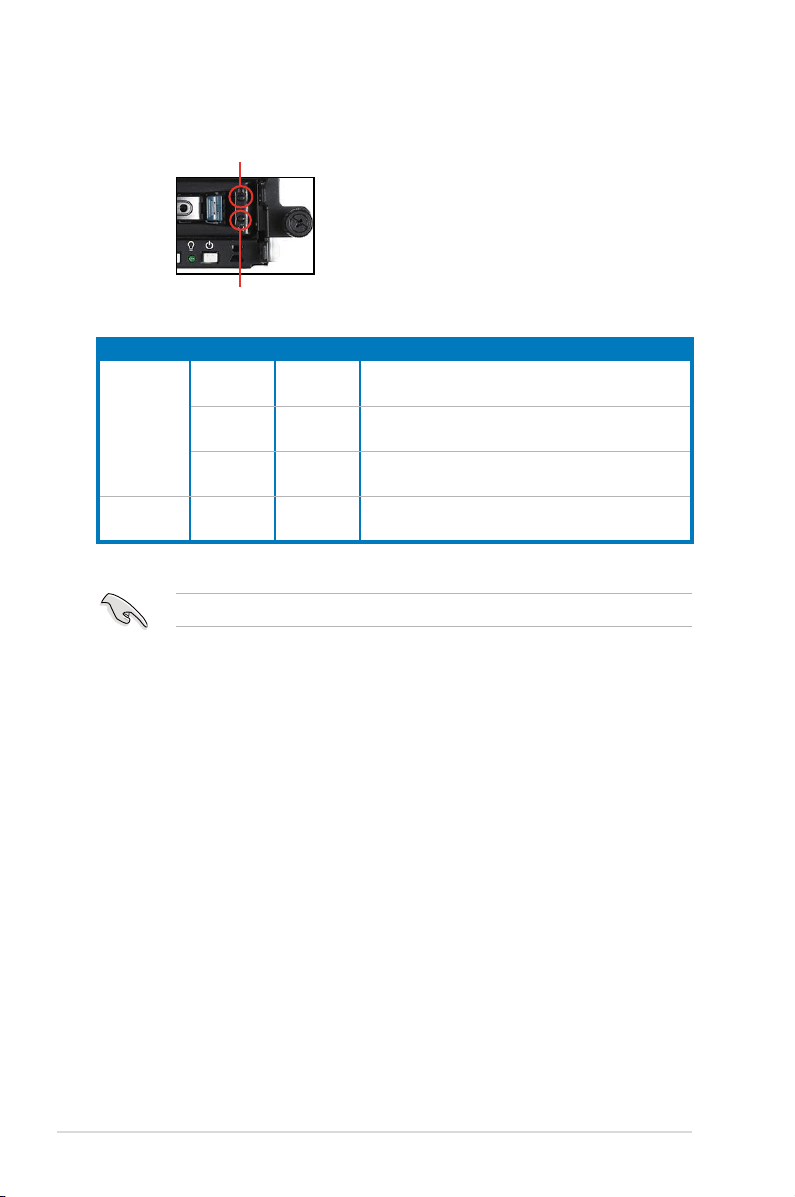
1.7.1 Front panel LEDs
HDD Access LED
LAN2 LED
LAN1 LED
LED Icon Display status Description
Power LED ON System power ON
HDD Access LED
Message LED
Location LED
LAN LEDs
The Message LED functions only when you install the optional ASMB4-iKVM
server management board. Contact the local sales or dealer for detailed
information on purchasing the server management board.
Message LED
OFF
Blinking
OFF
Blinking
OFF
ON
OFF
Blinking
ON
Power LED
Location LED
No activity
Read/write data into the HDD
System is normal; no incoming event
ASWM indicates a HW monitor event
Normal status
Location switch is pressed
(Press the location switch again to turn off)
No LAN connection
LAN is transmitting or receiving data
LAN connection is present
1.7.2 LAN (RJ-45) LEDs
SPEED LED
ACT/LINK LED
ACT/LINK LED SPEED LED
Status Description Status Description
OFF No link OFF 10 Mbps connection
GREEN Linked ORANGE 100 Mbps connection
BLINKING Data activity GREEN 1 Gbps connection
ASUS RS500A-E6/PS4 1-7
Page 18
1.7.3 HDD status LED
HDD status LED
HDD Activity LED
SATAII/SAS HDD LED Description
GREEN ON SATAII/SAS HDD power ON
HDD Status
LED
HDD Activity
LED
RED* ON
GREEN/
RED*
GREEN Blinking Read/write data from/into the SATAII/SAS HDD
*The LED status functions only when you install the optional PIKE RAID card.
Blinking RAID rebuilding
HDD has failed and should be swapped
immediately
Chapter 1: Product introduction1-8
Page 19

Chapter 2
This chapter lists the hardware setup
procedures that you have to perform
when installing or removing system
components.
ASUS RS500A-E6/PS4
Hardware setup
2-
Page 20
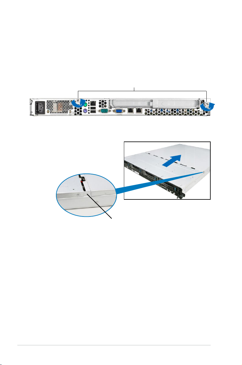
2.1 Chassis cover
Removing the rear cover
1. Loosen the two thumbscrews on the rear panel to release the rear cover from
the chassis.
Thumbscrews
2. Firmly hold the cover and slide it
toward the rear panel for about half
an inch until it is disengaged from
the chassis.
1/2 inch distance
3. Lift the cover from the chassis.
Chapter 2: Hardware setup2-2
Page 21
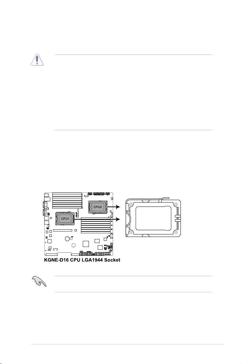
2.2 Central Processing Unit (CPU)
The motherboard comes with dual surface mount LGA 1944 Socket designed for
the AMD® Opteron™ 6100 series CPU in the Land Grid Array (LGA) package.
• Upon purchase of the motherboard, ensure that the PnP cap is on
the socket and the socket contacts are not bent. Contact your retailer
immediately if the PnP cap is missing, or if you see any damage to the PnP
cap/socket contacts/motherboard components. ASUS shoulders the repair
cost only if the damage is shipment/transit-related.
• Keep the cap after installing the motherboard. ASUS will process Return
Merchandise Authorization (RMA) requests only if the motherboard comes
with the cap on the Socket 1944.
• The product warranty does not cover damage to the socket contacts
resulting from incorrect CPU installation/removal, or misplacement/loss/
incorrect removal of the PnP cap.
2.2.1 Installing the CPU
To install a CPU:
1. Locate the CPU socket on the motherboard.
Before installing the CPU, ensure that the socket box is facing toward you and
the load lever is on your left.
2-3ASUS RS500A-E6/PS4
Page 22
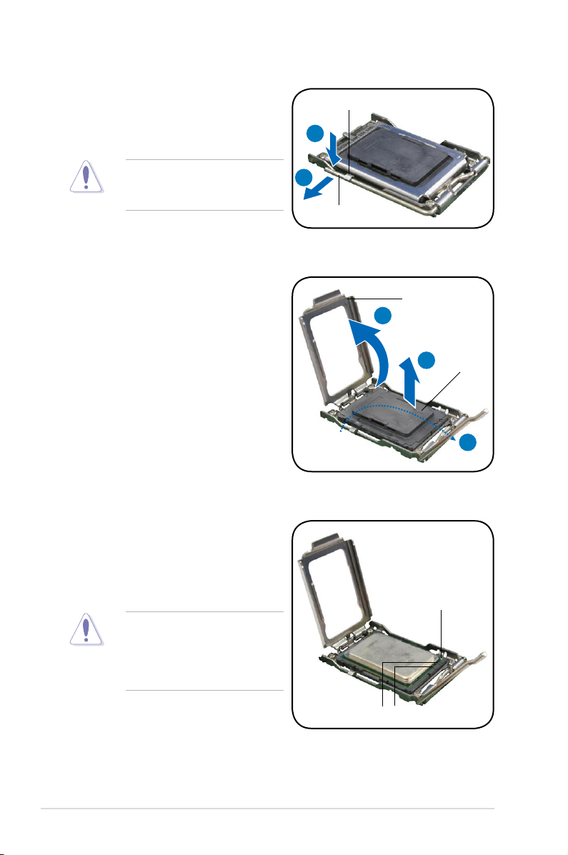
2. Press the load lever with your
thumb (A), then move it to the left
(B) until it is released from the
retention tab.
Retention tab
A
To prevent damage to the socket
pins, do not remove the PnP cap
unless you are installing a CPU.
3. Lift the load lever in the direction of
the arrow to a 135º angle.
4. Lift the load plate with your thumb
and forenger to a 100º angle.
5. Remove the PnP cap from the CPU
socket.
6. Position the CPU over the socket,
ensuring that the gold triangle is on
the bottom-right corner of the socket,
and then t the socket alignment key
into the CPU notch.
B
Load lever
Load plate
4
5
Gold triangle mark
PnP cap
3
The CPU ts in only one correct
orientation. DO NOT force the
CPU into the socket to prevent
bending the connectors on the
socket and damaging the CPU!
Alignment keys
Chapter 2: Hardware setup2-4
Page 23
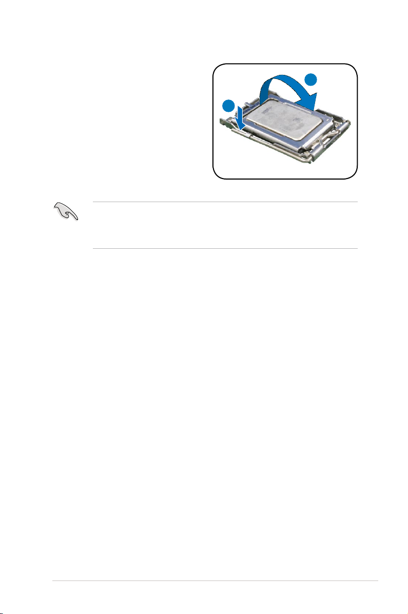
7. Close the load plate (A), then push
the load lever (B) until it snaps into
the retention tab.
Apply some Thermal Interface Material to the exposed area of the CPU that the
heatsink will be in contact with, ensuring that it is spread in an even thin layer.
Some heatsinks come with pre-applied Thermal Interface Material. If so, skip
this step.
A
B
2-5ASUS RS500A-E6/PS4
Page 24
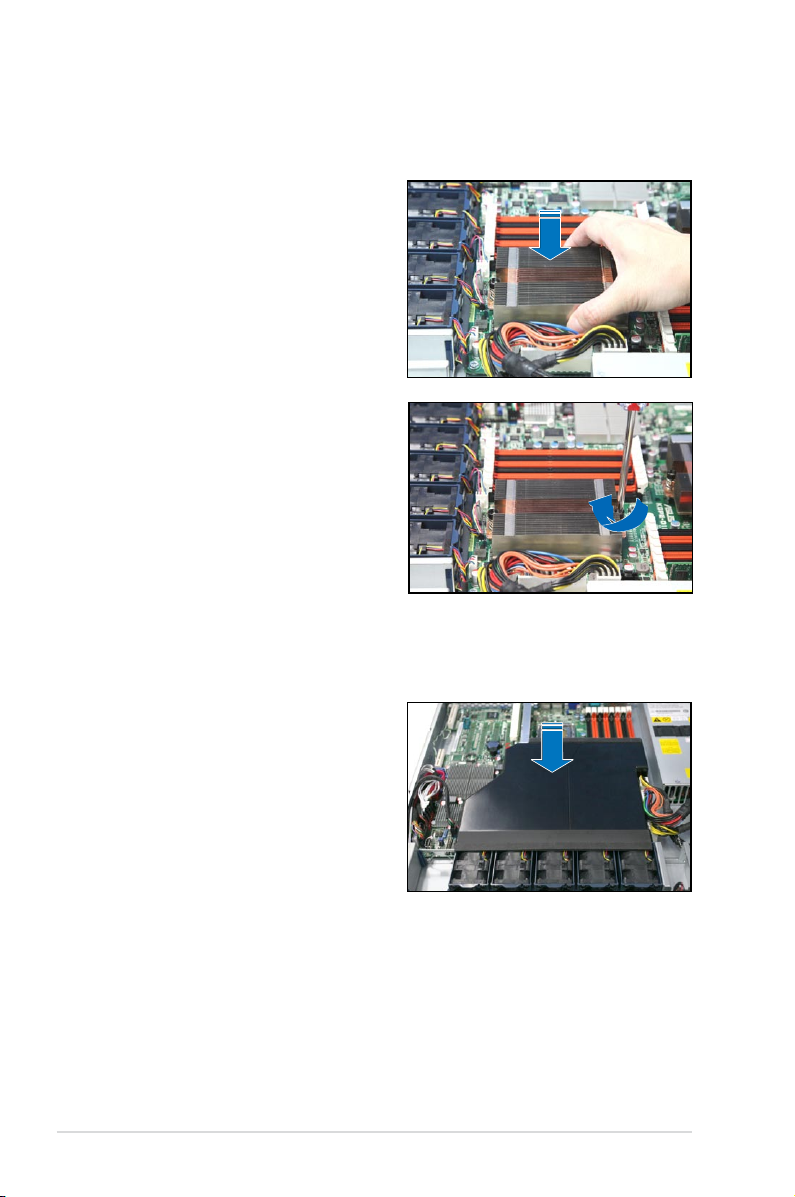
2.2.2 Installing the CPU heatsink and airduct
To install the CPU heatsink:
1. Place the heatsink on top of the
installed CPU, ensuring that the two
fasteners match the holes on the
motherboard.
2. Twist each of the two screws with
a Philips (cross) screwdriver just
enough to attach the heatsink to
the motherboard. When the two
screws are attached, tighten them
one by one to completely secure
the heatsink.
To install the airduct:
1. Position the airduct on top of the
heatsink.
2. Carefully lower the airduct until it
ts in place.
Chapter 2: Hardware setup2-6
Page 25
2.3 System memory
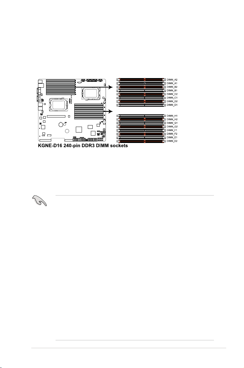
2.3.1 Overview
The motherboard comes with sixteen (16) Double Data Rate 3 (DDR3) Dual Inline
Memory Modules (DIMM) sockets.
The gure illustrates the location of the DDR3 DIMM sockets:
2.3.2 MemoryCongurations
You may install 1GB/2GB/4GB/8GB/16GB Registerd or 1GB/2GB/4GB Unbuffered
with ECC/Non-ECC DDR3 DIMMs into the DIMM sockets using the memory
congurations in this section.
• Always install DIMMs with the same CAS latency. For optimum
compatibility, it is recommended that you obtain memory modules from the
same vendor.
• For CPU1 conguraton, install DIMMs from the orange slots and in the
order as follows: DIMM_A2 -> DIMM_C2 -> DIMM_B2 -> DIMM_D2.
For CPU1 + CPU2 conguraton, install DIMMs from the orange slots and in
the order as follows: DIMM_A2 -> DIMM_E2 -> DIMM_C2 -> DIMM_G2.
•
For Quad Ranks DIMMs, when installing less than or equal to four
DIMMs:
For CPU1 conguration, install DIMMs to the orange slots and in the order
as follows: DIMM_A2 -> DIMM_C2 -> DIMM_B2 -> DIMM_D2.
For CPU1 + CPU2 conguration, install DIMMs to the orange slots and in
the order as follows: DIMM_A2 -> DIMM_E2 -> DIMM_C2 -> DIMM_G2.
•
For Quad Ranks DIMMs, when installing more than four DIMMs:
For CPU1 conguration, install DIMMs in the order as follows: DIMM_A2
-> DIMM_C2 -> DIMM_B2 -> DIMM_D2 -> DIMM_A1 -> DIMM_C1 ->
DIMM_B1 -> DIMM_D1.
For CPU1 + CPU2 conguration, install DIMMs in the order as follows:
DIMM_A2 -> DIMM_E2 -> DIMM_C2 -> DIMM_G2 -> DIMM_B2 ->
DIMM_F2 -> DIMM_D2 -> DIMM_H2 --> DIMM_A1 -> DIMM_E1 ->
DIMM_C1 -> DIMM_G1 -> DIMM_B1 -> DIMM_F1 -> DIMM_D1 ->
DIMM_H1.
2-7ASUS RS500A-E6/PS4
Page 26
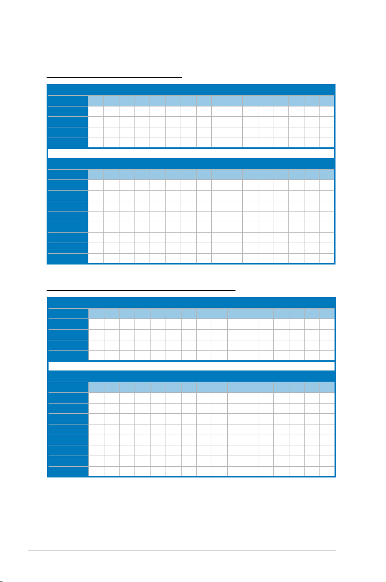
Memory population table
For UDIMM (Single Rank, Dual Ranks)
CPU1Conguration
A2 A1 B2 B1 C2 C1 D2 D1
2 DIMMs
4 DIMMs
6 DIMMs
8 DIMMs
CPU1+CPU2Conguration
2 DIMMs
4 DIMMs
6 DIMMs
8 DIMMs
10 DIMMs
12 DIMMs
14 DIMMs
16 DIMMs
For RDIMM (Single Rank, Dual Ranks & Quad Ranks)
CPU1Conguration
2 DIMMs
4 DIMMs
6 DIMMs
8 DIMMs
V V
V V V V
V V V V V V
V V V V V V V V
A2 A1 B2 B1 C2 C1 D2 D1 E2 E1 F2 F1 G2 G1 H2 H1
V V
V V V V
V V V V V V
V V V V V V V V
V V V V V V V V V V
V V V V V V V V V V V V
V V V V V V V V V V V V V V
V V V V V V V V V V V V V V V V
A2 A1 B2 B1 C2 C1 D2 D1
V V
V V V V
V V V V V V
V V V V V V V V
CPU1+CPU2Conguration
A2 A1 B2 B1 C2 C1 D2 D1 E2 E1 F2 F1 G2 G1 H2 H1
2 DIMMs
4 DIMMs
6 DIMMs
8 DIMMs
10 DIMMs
12 DIMMs
14 DIMMs
16 DIMMs
V V
V V V V
V V V V V V
V V V V V V V V
V V V V V V V V V V
V V V V V V V V V V V V
V V V V V V V V V V V V V V
V V V V V V V V V V V V V V V V
Chapter 2: Hardware setup2-8
Page 27
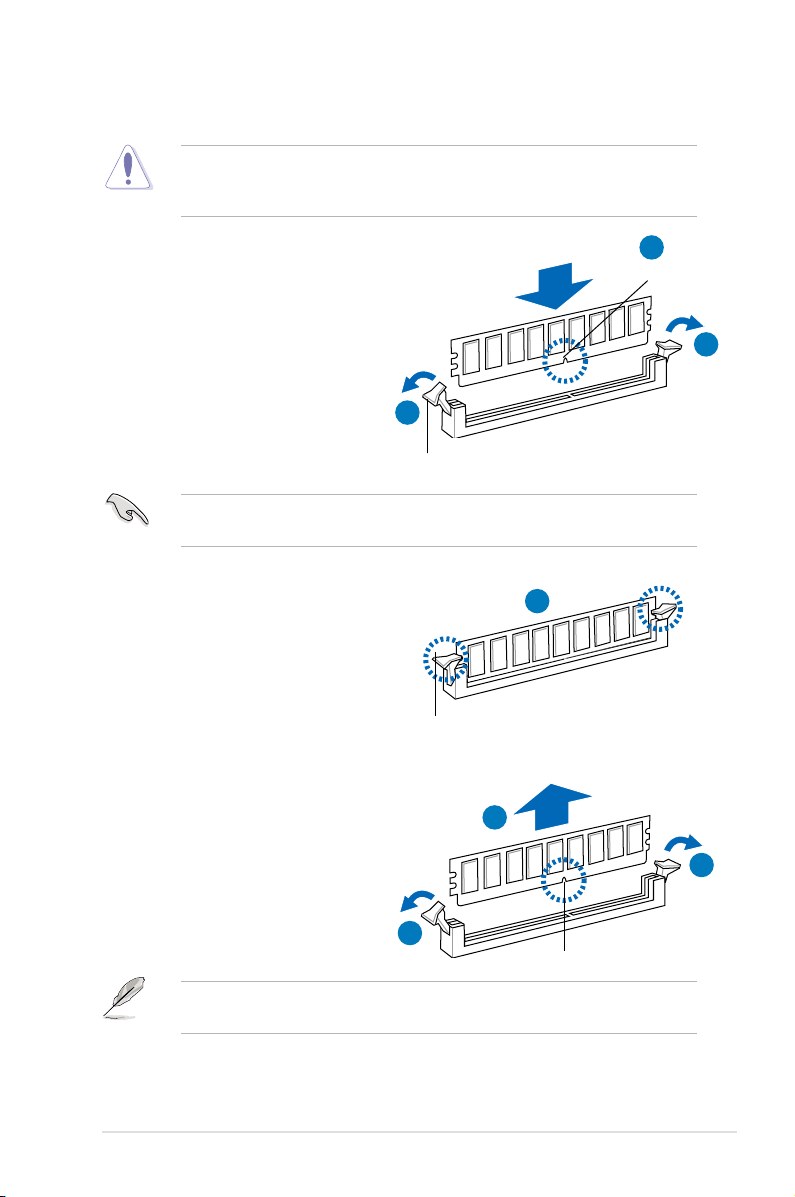
2.3.3 Installing a DIMM
Ensure to unplug the power supply before adding or removing DIMMs or other
system components. Failure to do so may cause severe damage to both the
motherboard and the components.
1. Unlock a DIMM socket by pressing
the retaining clips outward.
2. Align a DIMM on the socket
such that the notch on the DIMM
matches the break on the socket.
Unlocked retaining clip
A DIMM is keyed with a notch so that it ts in only one direction. DO NOT force
a DIMM into a socket to avoid damaging the DIMM.
2
DIMM notch
1
1
3. Firmly insert the DIMM into the
socket until the retaining clips snap
back in place and the DIMM is
properly seated.
Locked Retaining Clip
2.3.4 Removing a DIMM
Follow these steps to remove a DIMM.
1. Simultaneously press the
retaining clips outward to unlock
the DIMM.
1
Support the DIMM lightly with your ngers when pressing the retaining clips.
The DIMM might get damaged when it ips out with extra force.
2. Remove the DIMM from the socket.
3
2
1
DIMM notch
2-9ASUS RS500A-E6/PS4
Page 28
2.4 Hard disk drives
The system supports four hot-swap SATAII/SAS hard disk drives. The hard disk
drive installed on the drive tray connects to the motherboard SATAII/SAS ports via
the SATAII/SAS backplane.
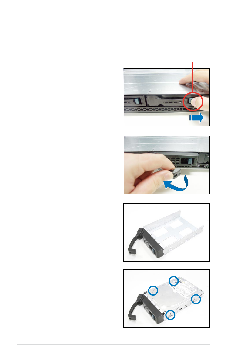
To install a hot-swap SATAII/SAS HDD:
1. Release a drive tray by pushing the
spring lock to the right, then pulling
the tray lever outward. The drive
tray ejects slightly after you pull out
the lever.
2. Firmly hold the tray lever and pull
the drive tray out of the bay.
spring lock
3. Take note of the drive tray holes.
Each side has three holes to t
different types of hard disk drives.
Use two screws on each side to
secure the hard disk drive.
4. Place a SATAII/SAS hard disk drive
on the tray, then secure it with four
screws.
Chapter 2: Hardware setup2-10
Page 29
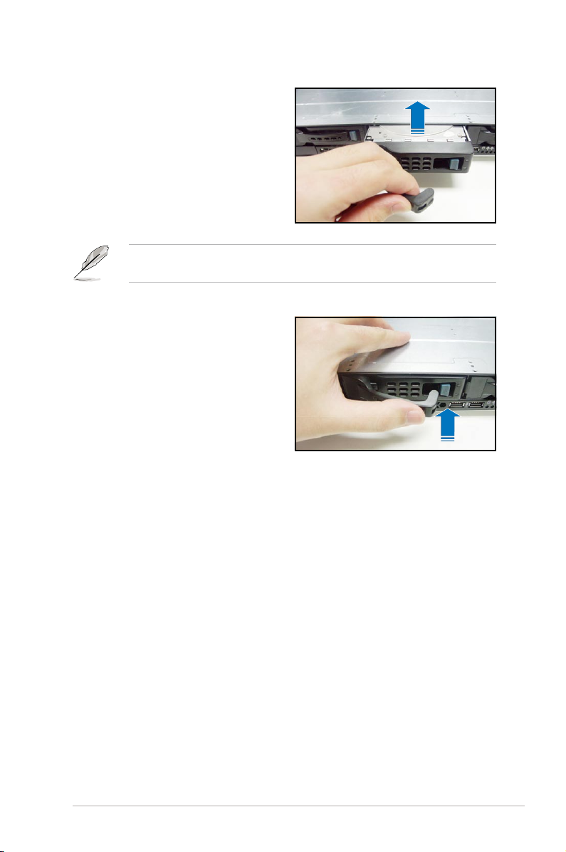
5. Carefully insert the drive tray and
push it all the way to the depth of
the bay until just a small fraction of
the tray edge protrudes.
When installed, the SATAII/SAS connector on the drive connects to the SATAII/
SAS interface on the backplane.
6. Push the tray lever until it clicks,
and secures the drive tray in place.
The drive tray is correctly placed
when its front edge aligns with the
bay edge.
7. Repeat steps 1 to 6 if you wish to
install a second SATAII/SAS drive.
2-11ASUS RS500A-E6/PS4
Page 30
2.5 Expansion slot
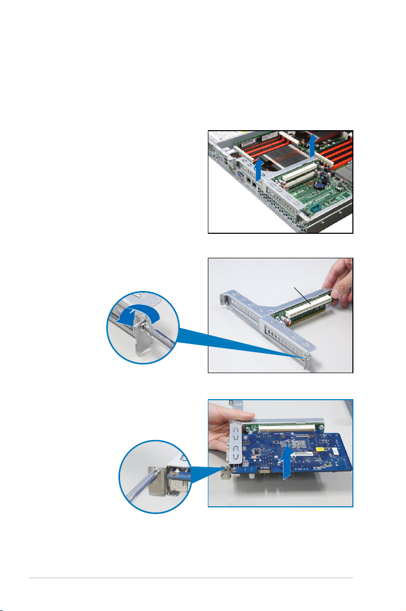
2.5.1 Installing an expansion card to the riser card bracket
The barebone server comes with a riser card bracket. You need to remove the
bracket if you want to install a PCI Express expansion card.
To install a PCI Express expansion card:
1. Firmly hold the riser card bracket,
then pull it up to detach it from
the PCI Express x16 slot on the
motherboard.
2. Place the riser card bracket on a
at and stable surface, then remove
the screw from the slot bay.
PCI Express x16 slot
3. Install a PCI Express expansion
card to the bracket as shown, then
secure the card with a screw.
Chapter 2: Hardware setup2-12
Page 31

To reinstall the riser card bracket:
1. Align the riser card bracket with the
cards to the PCI Express x16 slot
on the motherboard.
2. Press the riser card bracket until
the golden connectors completely
t the slot and the bracket aligns
with the rear panel.
3. Connect the cable(s) to the card, if
applicable.
2-13ASUS RS500A-E6/PS4
Page 32

2.5.2 Conguringanexpansioncard
After installing the expansion card, congure the it by adjusting the software
settings.
1. Turn on the system and change the necessary BIOS settings, if any. See
Chapter 5 for information on BIOS setup.
2. Assign an IRQ to the card. Refer to the following tables.
3. Install the software drivers for the expansion card.
Standard Interrupt assignments
IRQ Priority Standard function
0 1 System Timer
1 2 Keyboard Controller
2 - Programmable Interrupt
3* 11 Communications Port (COM2)
4* 12 Communications Port (COM1)
5* 13 --
6 14 Floppy Disk Controller
7* 15 --
8 3 System CMOS/Real Time Clock
9* 4 ACPI Mode when used
10* 5 IRQ Holder for PCI Steering
11* 6 IRQ Holder for PCI Steering
12* 7 PS/2 Compatible Mouse Port
13 8 Numeric Data Processor
14* 9 Primary IDE Channel
15* 10 Secondary IDE Channel
* These IRQs are usually available for ISA or PCI devices.
Chapter 2: Hardware setup2-14
Page 33

2.6 Cable connections
• The bundled system cables are pre-connected before shipment. You do
not need to disconnect these cables unless you will remove pre-installed
components to install additional devices.
• Refer to Chapter 4 for detailed information on the connectors.
2
2
1
3
5
8
Pre-connected system cables
1. 24-pin SSI power connector (from power supply to motherboard)
2. 8-pin SSI power connectors (from power supply to motherboard)
3. Power supply SMBus connector (from power supply to motherboard)
4. System fan connectors (from motherboard CPU_FAN2, FRNT_FAN1,
FRNT_FAN2, FRNT_FAN3, and FRNT_FAN4 to system fans)
5. USB connector (from motherboard to front I/O board)
6. Panel connector (from motherboard to front I/O board)
7. SATA connectors (from motherboard to SATAII/SAS backplane board)
8. SAS connectors (from motherboard to SATAII/SAS backplane board)
9. Auxiliary panel connector (from motherboard to front I/O board)
9
7
4
4
4
4
4
6
2-15ASUS RS500A-E6/PS4
Page 34

2.7 SATAII/SAS backplane cabling
SAS_SGPIO_CON1 connector*
SGPIO_SELjumper:
pins 1-2 (Onboard)
pins 2-3 (Add-on card)
Connects the data cables
connected to the motherboard
* For PIKE RAID solution, ensure to connect SAS_SGPIO_CON1 to the SGPIO1 connector on the
motherboard.
Connect the SATAII/SAS HDDs
Connects a
8-pin plug from
power supply
Chapter 2: Hardware setup2-16
Page 35

2.8 Removable/optional components
You may need to remove previously installed system components when installing
or removing system devices. Or you may need to install the optional components
into the system. This section tells how to remove/install the following components:
1. System fans
2. ASUS PIKE RAID card (optional)
3. ASUS ASMB4-iKVM (optional)
Ensure that the system is turned off before removing any components.
2.8.1 System fans
To uninstall the system fans:
1. Disconnect the system fan cable
from the fan connector on the
motherboard.
2. Lift the fan, then set aside.
3. Repeat steps 1 to 2 to uninstall the
other system fans.
To reinstall the system fans
1. Insert the fan to the fan cage. The
airow directional arrow on the
fan side should point towards the
system rear panel.
2. Connect the system fan cable to the
fan connector on the motherboard.
2-17ASUS RS500A-E6/PS4
Page 36

2.8.2 Installing ASUS PIKE RAID card (optional)
Follow the steps below to install an optional ASUS RAID card on your motherboard.
If you install the PIKE 1078 or PIKE 2008 Series SAS RAID card, follow steps 1
and 2 to remove the outer heatsink on RAID card.
1. Remove the two screws that secure
the heatsink bracket on the back of
the SAS RAID card.
Heatsink bracket
2. Remove the two screws that
secure the outer heatsink on the
front of the SAS RAID card.
DO NOT remove the inner
heatsink from the SAS RAID
card.
3. Locate the PIKE RAID card slot on
the motherboard.
4. Align the golden ngers of the RAID
card with the PIKE RAID card slot.
Chapter 2: Hardware setup2-18
Page 37

5. Insert the RAID card into the PIKE
RAID card slot. Ensure that it is
completely seated on the PIKE
RAID card slot.
6. Remove the data cables connected
to the SATA connectors on the
motherboard.
7. Connect the data cables, by
numerial order, to the SAS
connectors labeled SAS1-4 (red)
on the motherboard.
8. Set the SGPIO_SEL1 jumper on
the backplane to pin 2-3 when
connecting data cables to the SAS
connectors on the motherboard.
The heatsink on PIKE 1078/PIKE 2008 Series might interfere the components
on the expansion card. Ensure that the height of the components is less than
5.8 mm.
2-19ASUS RS500A-E6/PS4
Page 38

Installing i Button (for PIKE 1078 only)
Follow the steps below to install an optional i Button on your motherboard.
1. Locate the I Button slot on the
motherboard.
2. Snap the I Button in place.
Chapter 2: Hardware setup2-20
Page 39

2.8.3 Installing ASMB4 series management board (optional)
Follow the steps below to install an optional ASMB4 series management board on
your motherboard.
1. Locate the BMC_FW header on the
motherboard.
2. Orient and press the ASMB4
management card in place.
3. Insert the LAN cable plug to
the LAN port 3 (dedicated
LAN) or LAN port 1 (shared
LAN) for server management.
LAN port 3
LAN port 1
2-21ASUS RS500A-E6/PS4
Page 40

Chapter 2: Hardware setup2-22
Page 41

Chapter 3
This chapter describes how to install
the optional components and devices
into the barebone server.
ASUS RS500A-E6/PS4
Installation options
2-
Page 42

3.1 Installing friction rail kit items
Your friction rail kit package contains:
• Two pairs of rack rails (for the rack)
• Nut-and-bolt type screws and one pair of server latches
Nuts and screws Front rack rails Rear rack rails
3.1.1 Attachingthexinglatchestotheserver
Refer to the image below for the locations to attach the two xing latches to the two
sides of the server with four screws.
Fixing latch
Chapter 3: Installation options3-2
Page 43

3.1.2 Attaching the rack rails
To attach the rack rails
1. Place the two front rail rack joints into the rear rail rack slots, as shown in the
following gure.
2. Attach the front and rear rail racks with eight screws and nuts, as shown in
the following gure. Do not secure the screws too tight so that you can still
adjust the length of the rack rails to meet the depth of the server rack.
Front rail rackRear rail rack
Frontrailrackjoints
Rear rail rack slots
3. Select one unit of space (1U) on the rack where you want to install the
barebone server.
4. Measure the depth of the rack to determine the length of the rack rails.
5. Adjust the rack rail to ensure that it ts the rack.
6. Position the rack rail to the 1U space on the rack. Ensure that the front end of
the rack rail goes to the front of the rack space.
7. Secure the front end of the rail with
two rack screws, as shown in the
right gure.
8. Secure the rear end of the rail with
two rack screws, as shown in the
right gure.
9. Fasten the eight screw you secure
in step 2, as shown in the right
gure.
10. Repeat steps 6 to 9 to assemble
and attach the rack rail on the other
side.
9
8
7
8
9
7
3-3ASUS RS500A-E6/PS4
Page 44

3.1.3 Mounting the server to the rack
To mount the server to the rack
1. Place the server on the rack rails, and then push the server all the way to the
depth of the rack.
2. Tighten the two rack screws to
secure the server in place.
To uninstall the server from the rack
1. Loosen the rack screws that secured the server to the rack.
2. Pull the server from the rack.
Remember to press the latches
on both sides to release the
server from the rack.
Chapter 3: Installation options3-4
Page 45

3.2 Installing optional ball-bearing rail kit
items
Your optional ball-bearing rail kit package contains:
• two pair of server rails (for the server)
• two pairs of rack rails (for the rack)
• Nut-and-bolt type screws
Rack railsFront endRear endNuts and screws
3.2.1 Attaching the rails to the server
To attach the server rails:
1. Attach the front end of the server
rail to the side of the chassis,
matching each of the three hooks
to the holes on the rail. Then slide
the rail toward the front panel until it
locks in place.
2. Secure the front end of the server
rail to the side of the chassis with
one screw.
3-5ASUS RS500A-E6/PS4
Page 46

3. Attach the rear end of the server
rail to the side of the chassis,
matching each of the two hooks to
the holes on the rail. Then slide the
rail toward the front panel until it
locks in place.
4. Secure the rear end of the server
rail to the side of the chassis with
one screw.
5. Repeat steps 1 to 4 to attach the second server rail to the other side of the
chassis.
3.2.2 Attaching the rack rails
To attach the rack rails:
1. Select one unit of space (1U) on the rack where you want to install the
barebone server.
2. Install the nuts on the holes of the 1U space on the rack front.
3. Install the nuts on the holes of the 1U space on the corresponding rack rear.
4. Measure the depth of the rack to determine the length of the rack rails.
5. Measure the rack rail when assembled to ensure that it ts the rack.
6. Position the rack rail to the 1U space on the rack. Ensure that the front end of
the rack rail goes to the front of the rack space.
7. Secure the front end of the rail with
two rack screws.
8. Secure the rear end of the rail with
two rack screws.
9. Repeat steps 5 to 8 to assemble
and attach the second rack rail.
Chapter 3: Installation options3-6
Page 47

3.2.3 Mounting the server to the rack
To mount the server to the rack:
1. Align the server rails with the rack rails, then push the server all the way to
the depth of the rack.
2. Tighten the two rack screws to
secure the server in place.
To uninstall the server from the rack:
1. Loosen the rack screws that secured the server to the rack.
2. Pull the server from the rack.
Remember to press the latches
on both sides to release the
server from the rack.
3-7ASUS RS500A-E6/PS4
Page 48

Chapter 3: Installation options3-8
Page 49

Chapter 4
This chapter includes the motherboard
layout, and brief descriptions of the
jumpers and internal connectors.
ASUS RS500A-E6/PS4
Motherboard info
3-
4-1
Page 50

4.1 Motherboard layouts
4-2 Chapter 4: Motherboard information
Page 51

Layout contents
Jumpers Page
1. Clear RTC RAM (CLRTC1) 4-4
2. VGA controller setting (3-pin VGA_SW1))
3. CPU Fan and Chassis Fan control setting
(3-pin CPUFAN_SEL1, CHAFAN_SEL1)
4. LAN controller setting (3-pin LAN_SW1, LAN_SW2)
5. DDR3 voltage control setting
(4-pin LVDDR3_SEL1; LVDDR3_SEL2)
6. Force BIOS recovery setting (3-pin RECOVERY1)
Internal connectors Page
1. Serial ATA connectors
(7-pin SATA1, SATA2, SATA3, SATA4; RED)
(7-pin SATA5, SATA6; Black)
2. SAS connectors
(7-pin SAS1, SAS2, SAS3, SAS4; Red)
(7-pin SAS5, SAS6, SAS7, SAS8; Blue)
3. Hard disk activity LED connector (4-pin HDLED1)
4. USB connector (10-1 pin USB34, USB56; USB78; A-Type USB9)
5. Thermal sensor cable connectors (3-pin TR1, TR2)
6. CPU, front and rear fan connectors
(4-pin CPU_FAN1, CPU_FAN2, FRNT_FAN1, FRNT_FAN2,
FRNT_FAN3, FRNT_FAN4, FRNT_FAN5, REAR_FAN1)
7. Serial General Purpose Input/Output connectors
(8-1 pin SGPIO1/2)
8. Serial port connector (10-1 pin COM2)
9. BMC header (BMC_FW1)
10. TPM connector (20-1 pin TPM1)
11. Power Supply SMBus connector (5-pin PSUSMB1)
12. SSI power connectors
(24-pin SSIPWR1, 8-pin SSI12V1, 8-pin SSI12V2)
13. System panel connector (20-1 pin PANEL1)
14. Auxiliary panel connector (20-2 pin AUX_PANEL1)
4-5
4-5
4-6
4-6
4-7
4-8
4-8
4-9
4-9
4-10
4-10
4-11
4-11
4-12
4-12
4-13
4-13
4-14
4-15
ASUS RS500A-E6/PS4 4-3
Page 52

4.2 Jumpers
1. Clear RTC RAM (CLRTC1)
This jumper allows you to clear the Real Time Clock (RTC) RAM in CMOS.
You can clear the CMOS memory of date, time, and system setup parameters
by erasing the CMOS RTC RAM data. The onboard button cell battery
powers the RAM data in CMOS, which include system setup information such
as system passwords.
To erase the RTC RAM:
1. Turn OFF the computer and unplug the power cord.
2. Move the jumper cap from pins 1–2 (default) to pins 2–3. Keep the cap
on pins 2–3 for about 5–10 seconds, then move the cap back to pins 1–2.
3. Plug the power cord and turn ON the computer.
4. Hold down the <Del> key during the boot process and enter BIOS setup
to re-enter data.
Except when clearing the RTC RAM, never remove the cap on CLRTC jumper
default position. Removing the cap will cause system boot failure!
If the steps above do not help, remove the onboard battery and move the
jumper again to clear the CMOS RTC RAM data. After the CMOS clearance,
reinstall the battery.
4-4 Chapter 4: Motherboard information
Page 53

2. VGA controller setting (3-pin VGA_SW1)
This jumper allows you to enable or disable the onboard VGA controller. Set
to pins 1–2 to activate the VGA feature.
3. CPU Fan and Chassis Fan control setting
(3-pin CPUFAN_SEL1, CHAFAN_SEL1)
These jumpers allow you to switch for fan pin selection. The CPUFAN_SEL1
jumper is for the CPU fans control and the CHAFAN_SEL1 jumper is for the
front fans and rear fans control. Set to pins 1–2 when using 4-pin fans or pins
2–3 when using 3-pin fans.
• If you use a 4-pin fan but set the jumper to pin 2-3, the fan you installed
may not work.
• If you use a 3-pin fan but set the jumper for a 4-pin fan, the fan control will
not work and the fan you installed will always run at full speed.
ASUS RS500A-E6/PS4 4-5
Page 54

4. LAN controller setting (3-pin LAN_SW1, LAN_SW2)
These jumpers allow you to enable or disable the onboard Intel
®
82574L
Gigabit LAN controllers. Set to pins 1-2 to activate the Gigabit LAN feature.
5. DDR3 voltage control setting (4-pin LVDDR3_SEL1; LVDDR3_SEL2)
These jumpers allow you to adjust the DIMM voltage. Set to pins 1–2 to
select 1.5V BIOS control, pins 2–3 to select 1.2V Force or 3–4 to select
1.35V Force.
4-6 Chapter 4: Motherboard information
Page 55

6. Force BIOS recovery setting (3-pin RECOVERY1)
This jumper allows you to quickly update or recover the BIOS settings when it
becomes corrupted.
To update the BIOS:
1. Set the jumper to pins 2–3.
2. Insert the USB ash that contains the original or latest BIOS and turn on
the system to recover or update the BIOS.
3. Shut down the system.
4. Set the jumper back to pins 1–2.
5. Turn on the system.
ASUS RS500A-E6/PS4 4-7
Page 56

4.3 Internal connectors
1. Serial ATA connectors
(7-pin SATA1, SATA2, SATA3, SATA4; RED)
(7-pin SATA5, SATA6; Black)
Supported by the AMD® SP5100 chipset, these connectors are for the Serial
ATA signal cables for Serial ATA hard disk drives that allows up to 3Gb/s of
data transfer rate.
2. SAS connectors
(7-pin SAS1, SAS2, SAS3, SAS4; Red)
(7-pin SAS5, SAS6, SAS7, SAS8; Blue)
This motherboard comes with eight (8) Serial Attached SCSI (SAS) connectors,
the next-generation storage technology that supports both Serial Attached
SCSI (SAS) and Serial ATA (SATA). Each connector supports one device.
• These connectors function only when you install a PIKE RAID card.
• Connect the SAS hard disk drives to SAS connectors 1–4 (red) when
installing a 4-port PIKE RAID card.
4-8 Chapter 4: Motherboard information
Page 57

3. Hard disk activity LED connector (4-pin HDLED1)
This LED connector is for the storage add-on card cable connected to the
SATA or SAS add-on card. The read or write activities of any device connected
to the SATA or SAS add-on card causes the front panel LED to light up.
4. USB connector (10-1 pin USB34, USB56; USB78; A-Type USB9)
These connectors are for USB 2.0 ports. Connect the USB module cables to
connectors USB34 and USB56, then install the modules to a slot opening at
the back of the system chassis. These USB connectors comply with USB 2.0
specication that supports up to 480 Mbps connection speed.
ASUS RS500A-E6/PS4 4-9
Page 58

5. Thermal sensor cable connectors (3-pin TR1, TR2)
These connectors are for temperature monitoring. Connect the thermal
sensor cables to these connectors and place the other ends to the devices,
which you want to monitor temperature.
6. CPU, front and rear fan connectors
(4-pin CPU_FAN1, CPU_FAN2, FRNT_FAN1, FRNT_FAN2, FRNT_FAN3,
FRNT_FAN4, FRNT_FAN5, REAR_FAN1)
The fan connectors support cooling fans of 350 mA–740 mA (8.88 W max.)
or a total of 3.15 A–6.66 A (53.28 W max.) at +12V. Connect the fan cables to
the fan connectors on the motherboard, ensuring that the black wire of each
cable matches the ground pin of the connector.
• DO NOT forget to connect the fan cables to the fan connectors. Insufcient
air ow inside the system may damage the motherboard components.
• These are not jumpers! DO NOT place jumper caps on the fan connectors!
• All fans feature the ASUS Fan Speed technology.
4-10 Chapter 4: Motherboard information
Page 59

7. Serial General Purpose Input/Output connectors (8-1 pin SGPIO1/2)
These connectors are used for the SAS chip SGPIO interface that controls
the LED pattern generation, device information and general purpose data.
These connectors functions only when you install an ASUS PIKE SAS RAID
card.
8. Serial port connector (10-1 pin COM2)
This connector is for a serial (COM) port. Connect the serial port module
cable to this connector, then install the module to a slot opening at the back
of the system chassis.
The serial port module is purchased separately.
ASUS RS500A-E6/PS4 4-11
Page 60

9. BMC header (BMC_FW1)
The BMC connector on the motherboard supports an ASUS
®
Server
Management Board 4 Series (ASMB4).
10. TPM connector (20-1 pin TPM)
This connector supports a Trusted Platform Module (TPM) system, which can
securely store keys, digital certicates, passwords, and data. A TPM system
also helps enhance network security, protects digital identities, and ensures
platform integrity.
4-12 Chapter 4: Motherboard information
Page 61

11. Power Supply SMBus connector (5-pin PSUSMB1)
This connector allows you to connect SMBus (System Management Bus) to
the power supply unit to read PSU information. Devices communicate with an
SMBus host and/or other SMBus devices using the SMBus interface.
12. SSI power connectors
(24-pin SSIPWR1, 8-pin SSI12V1, 8-pin SSI12V2)
These connectors are for the SSI power supply plugs. The power supply
plugs are designed to t these connectors in only one orientation. Find the
proper orientation and push down rmly until the connectors completely t.
• DO NOT forget to connect the 24+8+8-pin power plugs; otherwise, the
system will not boot up.
• Use of a PSU with a higher power output is recommended when conguring
a system with more power-consuming devices. The system may become
unstable or may not boot up if the power is inadequate.
• Ensure that your power supply unit (PSU) can provide at least the minimum
power required by your system.
ASUS RS500A-E6/PS4 4-13
Page 62

13. System panel connector (20-pin PANEL1)
This connector supports several chassis-mounted functions.
1. System power LED (3-pin PLED)
This 3-pin connector is for the system power LED. Connect the chassis
power LED cable to this connector. The system power LED lights up
when you turn on the system power, and blinks when the system is in
sleep mode.
2. Message LED (2-pin MLED)
This 2-pin connector is for the message LED cable that connects to
the front message LED. The message LED is controlled by Hardware
monitor to indicate an abnormal event occurance.
3. System warning speaker (4-pin SPEAKER)
This 4-pin connector is for the chassis-mounted system warning
speaker. The speaker allows you to hear system beeps and warnings.
4. Hard disk drive activity LED (2-pin HDDLED)
This 2-pin connector is for the HDD Activity LED. Connect the HDD
Activity LED cable to this connector. The IDE LED lights up or ashes
when data is read from or written to the HDD.
5. SSI power button/soft-off button (2-pin PWRSW)
This connector is for the system power button. Pressing the power
button turns the system on or puts the system in sleep or soft-off mode
depending on the BIOS settings. Pressing the power switch for more
than four seconds while the system is ON turns the system OFF.
6. Reset button (2-pin RESET)
This 2-pin connector is for the chassis-mounted reset button for system
reboot without turning off the system power.
4-14 Chapter 4: Motherboard information
Page 63

14. Auxiliary panel connector (20-pin AUX_PANEL1)
This connector is for additional front panel features including front panel
SMB, locator LED and switch, chassis intrusion, and LAN LEDs.
1. Front panel SMB (6-1 pin FPSMB)
These leads connect the front panel SMBus cable.
2. LAN activity LED (2-pin LAN1_LED, LAN2_LED
)
These leads are for Gigabit LAN activity LEDs on the front panel.
3. Chassis intrusion (4-1 pin CHASSIS)
These leads are for the intrusion detection feature for chassis with
intrusion sensor or microswitch. When you remove any chassis
component, the sensor triggers and sends a high-level signal to these
leads to record a chassis intrusion event. The default setting is short
CASEOPEN and GND pin by jumper cap to disable the function.
4. Locator LED (2-pin LOCATORLED1 and 2-pin LOCATORLED2)
These leads are for the locator LED1 and LED2 on the front panel.
Connect the Locator LED cables to these 2-pin connector. The LEDs will
light up when the Locator button is pressed.
5. Locator Button/Swich (2-pin LOCATORBTN)
These leads are for the locator button on the front panel. This button
queries the state of the system locator.
ASUS RS500A-E6/PS4 4-15
Page 64

4-16 Chapter 4: Motherboard information
Page 65

Chapter 5
This chapter tells how to change
the system settings through the BIOS
Setup menus. Detailed descriptions of
the BIOS parameters are also provided.
ASUS RS500A-E6/PS4
BIOS setup
3-
Page 66

5.1 Managing and updating your BIOS
The following utilities allow you to manage and update the motherboard Basic
Input/Output System (BIOS) setup:
1.
ASUS EZ Flash 2
2.
BUPDATER utility
(Updates the BIOS using a USB ash disk.)
(Updates the BIOS in DOS mode using a bootable USB
ash disk drive.)
3.
ASUS CrashFree BIOS 3
(To recover the BIOS using a bootable USB ash
disk drive when the BIOS le fails or gets corrupted.)
Refer to the corresponding sections for details on these utilities.
Save a copy of the original motherboard BIOS le to a bootable
disk drive
motherboard BIOS using the ASUS Update or AFUDOS utilities.
in case you need to restore the BIOS in the future. Copy the original
USB ash
5.1.1 ASUS EZ Flash 2 utility
The ASUS EZ Flash 2 feature allows you to update the BIOS without having to use
a DOS-based utility.
Before you start using this utility, download the latest BIOS from the ASUS
website at www.asus.com.
To update the BIOS using EZ Flash 2
1. Insert the USB ash disk that contains the latest BIOS le to the USB port.
2. Enter the BIOS setup program. Go to the
and press <Enter> to enable it.
Or, press <Alt> + <F2> during the POST to enable EZ Flash 2.
menu to select
Tools
EZ Flash 2
ASUSTek EZ Flash 2 BIOS ROM Utility V4.16
Current ROM
BOARD: KGNE-D16
VER: 0201
DATE: 04/30/2010
PATH: A:\
A:
Note
[Enter] Select or Load [Tab] Switch [V] Drive Info
[Up/Down/Home/End] Move [B] Backup [Esc] Exit
5-2 Chapter 5: BIOS setup
Update ROM
BOARD: KGNE-D16
VER: 0202
DATE: 05/21/2010
Page 67

3. Press <Tab> to switch between drives until the correct BIOS le is
found. When found, EZ Flash 2 performs the BIOS update process and
automatically reboots the system when done.
• This function can support devices such as a USB ash disk with FAT 32/16
format and single partition only.
• DO NOT shut down or reset the system while updating the BIOS to prevent
system boot failure!
Ensure to load the BIOS default settings to ensure system compatibility and
stability. Select the Load Setup Defaults item under the Exit menu. See
section 5.9 Exit Menu for details.
5.1.2 BUPDATER utility
The succeeding BIOS screens are for reference only. The actual BIOS screen
displays may not be the same as shown.
The BUPDATER utility allows you to update the BIOS le in DOS environment
using a bootable USB ash disk drive with the updated BIOS le.
UpdatingtheBIOSle
To update the BIOS le using the BUPDATER utility:
1. Visit the ASUS website at www.asus.com and download the latest BIOS le
for the motherboard. Save the BIOS le to a bootable USB ash disk drive.
2. Copy the BUPDATER utility (BUPDATER.exe) from the ASUS support
website at support.asus.com to the bootable USB ash disk drive you created
earlier.
3. Boot the system in DOS mode, then at the prompt, type:
BUPDATER /i[lename].ROM
where [lename] is the latest or the original BIOS le on the bootable USB
ash disk drive, then press <Enter>.
A:\>BUPDATER /i[le name].ROM
ASUS RS500A-E6/PS4 5-3
Page 68

4. The utility veries the le, then starts updating the BIOS le.
ASUSTek BIOS Update for DOS V1.06 (09/08/04)
FLASH TYPE: MXIC 25L1605A
Current ROM
BOARD: KGNE-D16
VER: 0201
DATE: 04/30/2010
PATH:
WARNING! Do not turn off power during ash BIOS
Note
Writing BIOS:
Update ROM
BOARD: KGNE-D16
VER: 0202
DATE: 05/21/2010
DO NOT shut down or reset the system while updating the BIOS to prevent
system boot failure!
5. The utility returns to the DOS prompt after the BIOS update process is
completed. Reboot the system from the hard disk drive.
The BIOS update is nished! Please restart your system.
C:\>
5-4 Chapter 5: BIOS setup
Page 69

5.1.3 ASUS CrashFree BIOS 3 utility
The ASUS CrashFree BIOS 3 is an auto recovery tool that allows you to restore
the BIOS le when it fails or gets corrupted during the updating process. You can
update a corrupted BIOS le using a USB ash drive that contains the updated
BIOS le.
Prepare a USB ash drive containing the updated motherboard BIOS before
using this utility.
RecoveringtheBIOSfromaUSBashdrive
To recover the BIOS from a USB ash drive:
1. Insert the USB ash drive with the original or updated BIOS le to one USB
port on the system.
2. The utility will automatically recover the BIOS. It resets the system when the
BIOS recovery nished.
DO NOT shut down or reset the system while recovering the BIOS! Doing so
would cause system boot failure!
The recovered BIOS may not be the latest BIOS version for this motherboard.
Visit the ASUS website at www.asus.com to download the latest BIOS le.
ASUS RS500A-E6/PS4 5-5
Page 70

5.2 BIOS setup program
This motherboard supports a programmable rmware chip that you can update
using the provided utility described in section
.
BIOS
Use the BIOS Setup program when you are installing a motherboard, reconguring
your system, or prompted to “Run Setup.” This section explains how to congure
your system using this utility.
Even if you are not prompted to use the Setup program, you can change the
conguration of your computer in the future. For example, you can enable the
security password feature or change the power management settings. This
requires you to recongure your system using the BIOS Setup program so that the
computer can recognize these changes and record them in the CMOS RAM of the
rmware chip.
The rmware chip on the motherboard stores the Setup utility. When you start up
the computer, the system provides you with the opportunity to run this program.
Press <Del> during the Power-On Self-Test (POST) to enter the Setup utility;
otherwise, POST continues with its test routines.
If you wish to enter Setup after POST, restart the system by pressing
<Ctrl+Alt+Delete>, or by pressing the reset button on the system chassis. You can
also restart by turning the system off and then back on. Do this last option only if
the rst two failed.
The Setup program is designed to make it as easy to use as possible. Being a
menu-driven program, it lets you scroll through the various submenus and make
your selections from the available options using the navigation keys.
5.1 Managing and updating your
• The default BIOS settings for this motherboard apply for most conditions
to ensure optimum performance. If the system becomes unstable after
changing any BIOS settings, load the default settings to ensure system
compatibility and stability. Select the
Exit Menu. See section
• The BIOS setup screens shown in this section are for reference purposes
only, and may not exactly match what you see on your screen.
• Visit the ASUS website (www.asus.com) to download the latest BIOS le for
this motherboard.
5-6 Chapter 5: BIOS setup
5.9 Exit Menu
Load Setup Defaults
.
item under the
Page 71

5.2.1 BIOS menu screen
Menu items
Main Advanced Server Power Boot Tools Exit
System Time [13:44:30]
System Date [Fri 05/07/2010]
SATA 1 : [ST3160812AS]
SATA 2 : [Not Detected]
SATA 3 : [Not Detected]
SATA 4 : [Not Detected]
SATA 5 : [Not Detected]
SATA 6 : [Not Detected]
Storaga Conguration
System Information
Submenu items
Menu bar
v02.61 (C)Copyright 1985-2010, American Megatrends, Inc.
Congurationelds
BIOS SETUP UTILITY
General help
Use [ENTER], [TAB]
or [SHIFT-TAB] to
select a eld.
Use [+] or [-] to
congure system Time.
←→ Select Screen
↑↓ Select Item
+- Change Field
Tab Select Field
F1 General Help
F10 Save and Exit
ESC Exit
Navigation keys
5.2.2 Menu bar
The menu bar on top of the screen has the following main items:
Main For changing the basic system conguration
Advanced For changing the advanced system settings
Server For changing the advanced server settings
Power For changing the advanced power management (APM)
conguration
Boot For changing the system boot conguration
Tools For conguring options for special functions
Exit For selecting the exit options and loading default
settings
To select an item on the menu bar, press the right or left arrow key on the keyboard
until the desired item is highlighted.
5.2.3 Navigation keys
At the bottom right corner of a menu screen are the navigation keys for that
particular menu. Use the navigation keys to select items in the menu and change
the settings.
The navigation keys differ from one screen to another.
ASUS RS500A-E6/PS4 5-7
Page 72

5.2.4 Menu items
The highlighted item on the
menu bar displays the specic
items for that menu. For
example, selecting Main shows
the Main menu items.
System Time [11:17:09]
System Date [Fri 05/07/2010]
SATA1 [Not Detected]
SATA2 [Not Detected]
SATA3 [Not Detected]]
SATA4 [Not Detected]
SATA5 [Not Detected]
SATA6 [Not Detected]
Storage Conguration
System Information
Use [ENTER], [TAB]
or [SHIFT-TAB] to
select a eld.
Use [+] or [-] to
congure system Time.
The other items (Advanced,
Power, Boot, and Exit) on the
menu bar have their respective
menu items.
Main menu items
5.2.5 Submenu items
A solid triangle before each item on any menu screen means that the item has a
submenu. To display the submenu, select the item and press <Enter>.
5.2.6 Congurationelds
These elds show the values for the menu items. If an item is user-congurable,
you can change the value of the eld opposite the item. You cannot select an item
that is not user-congurable.
A congurable eld is enclosed in brackets, and is highlighted when selected. To
change the value of a eld, select it then press <Enter> to display a list of options.
Refer to 5.2.7 Pop-up window.
5.2.7 Pop-up window
Select a menu item then press <Enter> to display a pop-up window with the
conguration options for that item.
5.2.8 Scroll bar
A scroll bar appears on the right side of a
menu screen when there are items that do
not t on the screen. Press the Up/Down
arrow keys or <Page Up> /<Page Down>
keys to display the other items on the
screen.
Pop-up window
Scroll bar
5.2.9 General help
At the top right corner of the menu screen is a brief description of the selected
item.
5-8 Chapter 5: BIOS setup
Page 73

5.3 Main menu
When you enter the BIOS Setup program, the Main menu screen appears, giving
you an overview of the basic system information.
Refer to section 5.2.1 BIOS menu screen for information on the menu screen
items and how to navigate through them.
Main Advanced Server Power Boot Tools Exit
System Time [13:44:30]
System Date [Fri 05/07/2010]
SATA 1 : [ST3160812AS]
SATA 2 : [Not Detected]
SATA 3 : [Not Detected]
SATA 4 : [Not Detected]
SATA 5 : [Not Detected]
SATA 6 : [Not Detected]
Storage Conguration
System Information
v02.61 (C)Copyright 1985-2010, American Megatrends, Inc.
BIOS SETUP UTILITY
Use [ENTER], [TAB]
or [SHIFT-TAB] to
select a eld.
Use [+] or [-] to
congure system Time.
←→ Select Screen
↑↓ Select Item
+- Change Field
Tab Select Field
F1 General Help
F10 Save and Exit
ESC Exit
5.3.1 System Time [xx:xx:xx]
Allows you to set the system time.
5.3.2 System Date [Day xx/xx/xxxx]
Allows you to set the system date.
ASUS RS500A-E6/PS4 5-9
Page 74

5.3.3 SATA1–6
The items in this menu allow you to set or change the congurations for the SATA
devices installed in the system. Select an item then press <Enter> if you wish to
congure the item.
Main
SATA 5
Device :Hard Disk
Vendor :xxxxxxxxx
Size :xx.xGB
LBA Mode :Supported
Block Mode:16Sectors
PIO Mode :4
Async DMA :MultiWord DMA-2
Ultra DMA :Ultra DMA-6
S.M.A.R.T.:Supported
Type [Auto]
LBA/Large Mode [Auto]
Block(Multi-Sector Transfer)M [Auto]
PIO Mode [Auto]
DMA Mode [Auto]
SMART Monitoring [Auto]
32Bit Data Transfer [Enabled]
v02.61 (C)Copyright 1985-2010, American Megatrends, Inc.
The BIOS automatically detects the values opposite the dimmed items (Device,
Vendor, Size, LBA Mode, Block Mode, PIO Mode, Async DMA, Ultra DMA, and
S.M.A.R.T. monitoring). These values are not user-congurable. These items show
Not Detected if no SATA device is installed in the system.
Type [Auto]
Selects the type of SATA drive. Setting to [Auto] allows automatic selection of the
appropriate SATA device type. Select [CDROM] if you are specically conguring a
CD-ROM drive. Select [ARMD] (ATAPI Removable Media Device) if your device is
either a ZIP, LS-120, or MO drive.
Conguration options: [Not Installed] [Auto] [CDROM] [ARMD]
BIOS SETUP UTILITY
Disabled: Disables LBA
Mode.
Auto: Enables LBA
Mode if the device
supports it and the
device is not already
formatted with LBA
Mode disabled.
←→ Select Screen
↑↓ Select Item
+- Change Option
F1 General Help
F10 Save and Exit
ESC Exit
This item appears in SATA 5/6 only.
LBA/Large Mode [Auto]
Enables or disables the LBA mode. Setting to [Auto] enables the LBA mode if the
device supports this mode, and if the device was not previously formatted with LBA
mode disabled. Conguration options: [Disabled] [Auto]
Block (Multi-Sector Transfer) M [Auto]
Enables or disables data multi-sectors transfers. When set to [Auto], the data
transfer from and to the device occurs multiple sectors at a time if the device
supports multi-sector transfer feature. When set to [Disabled], the data transfer
from and to the device occurs one sector at a time.
Conguration options: [Disabled] [Auto]
5-10 Chapter 5: BIOS setup
Page 75

PIO Mode [Auto]
Allows you to select the data transfer mode.
Conguration options: [Auto] [0] [1] [2] [3] [4]
DMA Mode [Auto]
DMA (Direct Memory Access) allows your computer to transfer data to and from the
hardware devices installed with much less CPU overhead.
The DMA mode consists of SDMA (single-word DMA), MDMA (multi-word DMA), and
UDMA (Ultra DMA). Setting to [Auto] allows automatic selection of the DMA mode.
SMART Monitoring [Auto]
Sets the Smart Monitoring, Analysis, and Reporting Technology.
Conguration options: [Auto] [Disabled] [Enabled]
32Bit Data Transfer [Enabled]
Enables or disables 32-bit data transfer.
Conguration options: [Disabled] [Enabled]
5.3.4 StorageConguration
The items in this menu allow you to set or change the congurations for the SATA
devices installed in the system. Select an item then press <Enter> if you wish to
congure the item.
Main
Storage Conguration
OnChip SATA Channel [Enabled]
SATA Port1 - Port4 [IDE]
SATA Port5 - Port6 [IDE]
BIOS SETUP UTILITY
Disabled
Enabled
Options
←→ Select Screen
↑↓ Select Item
+- Change Option
F1 General Help
F10 Save and Exit
ESC Exit
v02.61 (C)Copyright 1985-2010, American Megatrends, Inc.
OnChip SATA Channel [Enabled]
Allows you to enable or disable the onboard SATA channel.
Conguration options: [Disabled] [Enabled]
ASUS RS500A-E6/PS4 5-11
Page 76

The following two items appear only when you set the OnChip SATA Channel
item to [Enabled].
SATA Port1 - Port4 [IDE]
Sets the conguration for the Serial ATA connectors supported by the Southbridge
chip. Conguration options: [IDE] [AHCI]
• If you want to use the Serial ATA hard disk drives as Parallel ATA physical
storage devices, keep the default setting [IDE].
• If you want the Serial ATA hard disk drives to use the Advanced Host
Controller Interface (AHCI), set this item to [AHCI]. The AHCI allows
the onboard storage driver to enable advanced Serial ATA features that
increases storage performance on random workloads by allowing the drive
to internally optimize the order of commands.
• When this item is set [AHCI], the information of the SATA connectors 1–6
can be seen only under the OS environment or during POST.
SATA Port5 - Port6 [IDE]
Setting this item to [IDE] instead of [AHCI] allows the system to recognize the
optical dirves connected to the SATA connectors 5 or 6 when installing OS.
If you use a SATA optical drive to run the OS installation disk, we strongly
recommend that you install the optical dirve to the SATA connectors 5/6 and set
them to [IDE] mode.
5.3.5 System Information
This menu gives you an overview of the general system specications. The BIOS
automatically detects the items in this menu.
Main
BIOS Information
Version :0201
Build Date :04/30/10
Processor
Type :AMD Opteron(tm) Processor 6172
Speed :2100MHZ
System Memory
Usable Size : 2048MB
BIOS SETUP UTILITY
System Memory Information
v02.61 (C)Copyright 1985-2010, American Megatrends, Inc.
←→ Select Screen
↑↓ Select Item
Enter Go to Sub Screen
F1 General Help
F10 Save and Exit
ESC Exit
5-12 Chapter 5: BIOS setup
Page 77

BIOS Information
Displays the auto-detected BIOS information.
Processor
Displays the auto-detected CPU specication.
System Memory
Displays the auto-detected system memory.
System Memory Information
Displays system memory information.
Main
System Memory Information
CPU1 Memory Conguration
CPU2 Memory Conguration
CPU1/2 Memory Configuration
Allows you to check information of installed memory (8 DIMMs per CPU).
CPU1/2MemoryConguration
Displays the auto-detected memory specication.
BIOS SETUP UTILITY
Main
CPU1 Memory Conguration
Node0 Speed DDR3 1067
Node1 Speed N/A
DIMM_A1 N/A
DIMM_A2 2048 MB, 2R, 1067
DIMM_B1 N/A
DIMM_B2 N/A
DIMM_C1 N/A
DIMM_C2 N/A
DIMM_D1 N/A
DIMM_D2 N/A
BIOS SETUP UTILITY
ASUS RS500A-E6/PS4 5-13
Page 78

5.4 Advanced menu
The Advanced menu items allow you to change the settings for the CPU and other
system devices.
Take caution when changing the settings of the Advanced menu items. Incorrect
eld values can cause the system to malfunction.
Main Advanced Server Power Boot Tools Exit
CPU Conguration
Chipset Conguration
Onborad Devices Conguration
USB Conguration
PCIPnP
v02.61 (C)Copyright 1985-2010, American Megatrends, Inc.
BIOS SETUP UTILITY
Congure CPU.
←→ Select Screen
↑↓ Select Item
Enter Go to Sub Screen
F1 General Help
F10 Save and Exit
ESC Exit
5.4.1 CPUConguration
The items in this menu show the CPU-related information that the BIOS
automatically detects. Some items may not appear if your CPU does not support
the related functions.
Advanced
CPU Conguration
Module Version: 5.1102.1
Physical Count: 2
Logical Count : 12
AMD Opteron(tm) Processor 6172
Revision: D1
Cache L1: 128KB
Cache L2: 512KB
Cache L3: 12MB
Speed : 2100MHz, NB Clk: 1800MHz
Able to Change Freq. : Yes
uCode Patch Level : 0x10000C4
GART Error Reporting [Disabled]
Microcode Updation [Enabled]
Secure Virtual Machine Mode [Enabled]
PowerNow [Enabled]
PowerCap [P-state 0]
ACPI SRAT Table [Enabled]
C1E Support [Enabled]
v02.61 (C)Copyright 1985-2010, American Megatrends, Inc.
BIOS SETUP UTILITY
This option should
remain disabled for
the normal operation.
The driver developer
may enable it for
testing purpose.
←→ Select Screen
↑↓ Select Item
+- Change Option
F1 General Help
F10 Save and Exit
ESC Exit
Scroll down for more items.
CPU2 [Enabled]
v02.61 (C)Copyright 1985-2010, American Megatrends, Inc.
5-14 Chapter 5: BIOS setup
Page 79

GART Error Reporting [Disabled]
This option should remain disabled for the normal operation. The driver developer
may enable it for testing purpose. Conguration options: [Disabled] [Enabled]
Microcode Updation [Enabled]
Allows the system to update the Microcode automatically, enhancing system
performance. Conguration options: [Disabled] [Enabled]
Secure Virtual Machine Mode [Enabled]
Allows you to enable or disable the AMD Secure Virtual Machine.
Conguration options: [Disabled] [Enabled]
PowerNow [Enabled]
Allows you to enable or disable the generation of ACPI_PPC/_PSS/_PCT objects.
Conguration options: [Enabled] [Disabled]
PowerCap [P-state 0]
Allows you to select the highest performance P-state in OS.
Conguration options: [P-state 0] [P-state 1] [P-state 2] [P-state 3] [P-state 4]
ACPI SRAT Table [Enabled]
Allows you to enable or disable the building of ACPI SRAT Table.
Conguration options: [Enabled] [Disabled]
C1E Support [Enabled]
Allows you to enable or disable the C1E support function. This item should be
enabled in order to enable the Enhanced Halt State.
Conguration options: [Disabled] [Enabled]
CPU2 [Enabled]
Allows you to enable or disable CPU2.
Conguration options: [Enabled] [Disabled]
ASUS RS500A-E6/PS4 5-15
Page 80

5.4.2 ChipsetConguration
The Chipset conguration menu allows you to change advanced chipset settings.
Select an item then press <Enter> to display the submenu.
Advanced
Advanced Chipset Settings
NorthBridge Conguration
SouthBridge Conguration
SR5650 Conguration
v02.61 (C)Copyright 1985-2010, American Megatrends, Inc.
BIOS SETUP UTILITY
Options for NB
←→ Select Screen
↑↓ Select Item
Enter Go to Sub Screen
F1 General Help
F10 Save and Exit
ESC Exit
NorthBridgeConguration
Advanced
NorthBrideg Chipset Conguration
Memory Conguration
ECC Conguration
DRAM Timing Conguration
Memroy Timing Parameters [CPU Node 0]
Memory CLK :533 MHz, N/A
CAS Latency(Tcl) :7 CLK , N/A
RAS/CAS Delay(Trcd) :7 CLK , N/A
Row Precharge Time(Trp):7 CLK , N/A
Min Active RAS(Tras) :20 CLK, N/A
RAS/RAS Delay(Trrd) :4 CLK, N/A
Row Cycle (Trc) :27 CLK, N/A
Read to Precharge(Trtp):4 CLK, N/A
Write Recover Time(Twr): 8 CLK, N/A
v02.61 (C)Copyright 1985-2010, American Megatrends, Inc.
BIOS SETUP UTILITY
←→ Select Screen
↑↓ Select Item
Enter Go to Sub Screen
F1 General Help
F10 Save and Exit
ESC Exit
5-16 Chapter 5: BIOS setup
Page 81

MemoryConguration
The memory conguration menu allows you to change the memory settings.
Advanced
Memory Conguration
Bank Interleaving [Auto]
Node Interleaving [Disabled]
Channel Interleaving [Auto]
CS Sparing Enable [Disabled]
Bank Swizzle Mode [Enabled]
V02.61 (C)Copyright 1985-2006, American Megatrends, Inc.
Bank Interleaving [Auto]
Enables the Bank memory interleaving.
Conguration options: [Disabled] [Auto]
Node Interleaving [Disabled]
Enables the Node memory interleaving.
Conguration options: [Disabled] [Auto]
Channel Interleaving [Auto]
Enables the Channel memory interleaving.
Conguration options: [Disabled] [Auto]
CS Sparing Enable [Disabled]
Allows you to reserve a spare memory rank in each node.
Conguration options: [Disabled] [Enabled]
Bank Swizzle Mode [Enabled]
Allows you to enable or disable the Bank Swizzle mode.
Conguration options: [Disabled] [Enabled]
BIOS SETUP UTILITY
Enable Bank Memory
Interleaving
←→ Select Screen
↑↓ Select Item
+- Change Option
F1 General Help
F10 Save and Exit
ESC Exit
ASUS RS500A-E6/PS4 5-17
Page 82

ECCConguration
Advanced
ECC Conguration
ECC Mode [Basic]
DRAM ECC Enable [Enabled]
v02.61 (C)Copyright 1985-2010, American Megatrends, Inc.
ECC Mode [Basic]
Disables or sets the DRAM ECC mode that allows the hardware to report and
correct memory errors.
Conguration options: [Disabled] [Basic] [Good] [Super] [Max] [User]
BIOS SETUP UTILITY
Set the level of ECC
protection. Note: The
‘Super‘ ECC mode
dynamically sets the
DRAM scrub rate so
all of memory is
scrubbed in 8 hours.
←→ Select Screen
↑↓ Select Item
+- Change Option
F1 General Help
F10 Save and Exit
ESC Exit
DRAMTimingConguration
Advanced
DRAM Timing Conguration
DRAM Timing Cong [Auto]
BIOS SETUP UTILITY
Auto
Manual
Options
←→ Select Screen
↑↓ Select Item
+- Change Option
F1 General Help
F10 Save and Exit
ESC Exit
v02.61 (C)Copyright 1985-2010, American Megatrends, Inc.
DRAM Timing Config [Auto]
Allows you to select the DRAM timing mode. Conguration options: [Auto] [Manual]
Memory Clock Speed [400 MHz]
This item appears only when you set the
DRAMTimingCong
item to
[Manual] and allows you to set the memory clock frequency.
Conguration options: [400 MHz] [533 MHz] [667 MHz]
Memory Timing Parameters [CPU Node 0]
Allows you to select which node's timing parameters to display.
5-18 Chapter 5: BIOS setup
Page 83

SouthBridgeConguration
Advanced
SouthBridge Chipset Conguration
SP5100 CIMx Version : 5.5.0
SB Debug Conguration
OHCI HC (Bus 0 Dev 18 Fn 0) [Enabled]
OHCI HC (Bus 0 Dev 18 Fn 1) [Enabled]
EHCI HC (Bus 0 Dev 18 Fn 2) [Enabled]
OHCI HC (Bus 0 Dev 19 Fn 0) [Enabled]
OHCI HC (Bus 0 Dev 19 Fn 1) [Enabled]
EHCI HC (Bus 0 Dev 19 Fn 2) [Enabled]
OHCI HC (Bus 0 Dev 20 Fn 5) [Enabled]
v02.61 (C)Copyright 1985-2010, American Megatrends, Inc.
SBDebugConguration
Advanced
A15 ECOs [Disable]
Port 0 ESP [ISP]
Port 1 ESP [ISP]
Port 2 ESP [ISP]
Port 3 ESP [ISP]
Port 4 ESP [ISP]
Port 5 ESP [ISP]
Dis #THRMTRIP Before KBRst [Enabled]
SATA-IDE Ports Auto Clk Ctrl [Disable]
SATA-AHCI Ports Auto Clk Ctrl [Disable]
SATA PORT0 MODE [Auto]
SATA PORT1 MODE [Auto]
SATA PORT2 MODE [Auto]
SATA PORT3 MODE [Auto]
SATA PORT4 MODE [Auto]
SATA PORT5 MODE [Auto]
BIOS SETUP UTILITY
SouthBridge Debug Conguration
Options for SB
Debug Features
←→ Select Screen
↑↓ Select Item
Enter Go to Sub Screen
F1 General Help
F10 Save and Exit
ESC Exit
Options
Disable
Enabled
←→ Select Screen
↑↓ Select Item
+- Change Option
F1 General Help
F10 Save and Exit
ESC Exit
v02.61 (C)Copyright 1985-2010, American Megatrends, Inc.
A15 ECOs [Disable]
Conguration options: [Disable] [Enabled]
Port 0/1/2/3/4/5 ESP [ISP]
Selects the type or the Port ESP help.
Conguration options: [ISP] [ESP]
Dis #THRMTRIP Before KBRst [Enabled]
Conguration options: [Enabled] [Disabled]
SATA-IDE Ports Auto Clk Ctrl [Disable]
When set to [Enabled], the system will turn off the clocks for the unused SATA
ports in IDE modes. Doing so will enable some power savings.
Conguration options: [Disable] [Enabled]
The hot-plug function will be disabled when turning off the clock for the SATA
port.
ASUS RS500A-E6/PS4 5-19
Page 84

SATA-AHCI Ports Auto Clk Ctrl [Disable]
When set to [Enabled], the system will turn off the clocks for the unused SATA
ports in AHCI modes. Doing so will enable some power savings.
Conguration options: [Disable] [Enabled]
The hot-plug function will be disabled when turning off the clock for the SATA
port.
SATA PORT0/1/2/3/4/5 MODE [Auto]
When set to [GEN1], the SATA prot will run at GEN1 mode. Setting to [Auto]
will leave the SATA port to run at the default mode.
Conguration options: [Auto] [GEN1]
OHCI HC (Bus 0 Dev 18 Fn 0) [Enabled]
Conguration options: [Disabled] [Enabled]
OHCI HC (Bus 0 Dev 18 Fn 1) [Enabled]
Conguration options: [Disabled] [Enabled]
EHCI HC (Bus 0 Dev 18 Fn 2) [Enabled]
Conguration options: [Disabled] [Enabled]
OHCI HC (Bus 0 Dev 19 Fn 0) [Enabled]
Conguration options: [Disabled] [Enabled]
OHCI HC (Bus 0 Dev 19 Fn 1) [Enabled]
Conguration options: [Disabled] [Enabled]
EHCI HC (Bus 0 Dev 19 Fn 2) [Enabled]
Conguration options: [Disabled] [Enabled]
OHCI HC (Bus 0 Dev 20 Fn 5) [Enabled]
Conguration options: [Disabled] [Enabled]
5-20 Chapter 5: BIOS setup
Page 85

SR5650Conguration
Advanced
SR5650 Conguration
PCI Express Conguration
Hyper Transport Conguration
IOMMU [Disabled]
Primary Video Controller [Slot1-PIKE-PCI]
Debug Option
v02.61 (C)Copyright 1985-2010, American Megatrends, Inc.
PCIExpressConguration
Advanced
PCI Express Conguration
PCIE Slot 1 Features
PIKE Slot Features
NB-SB Port Features
PCIE Slot 1 Core Setting
PIKE Slot Core Setting
SB Core Setting
PCI Express Congurat
←→ Select Screen
↑↓ Select Item
Enter Go to Sub Screen
F1 General Help
F10 Save and Exit
ESC Exit
←→ Select Screen
↑↓ Select Item
Enter Go to Sub Screen
F1 General Help
F10 Save and Exit
ESC Exit
v02.61 (C)Copyright 1985-2010, American Megatrends, Inc.
PCIE Slot 1/PIKE Slot Features
Select an item, and then press <Enter> to display its sub-items.
Gen2 High Speed Mode [Auto]
Conguration options: [Auto] [Disabled] [Software Initiated] [Advertised RC]
Link ASPM [Disabled]
Conguration options: [Disabled] [L0s] [L1] [L0s & L1] [L0s Downstream]
[L0s Downstream + L1]
Compliance Mode [Disabled]
Conguration options: [Disabled] [Enable]
Lane Reversal [Disabled]
Conguration options: [Disabled] [Enabled]
ASUS RS500A-E6/PS4 5-21
Page 86

NB-SB Port Features
Press <Enter> to display the sub-items.
NB-SB Link ASPM [L1]
Conguration options: [Disabled] [L1]
NPNB-SBVC1TrafcSupport[Disabled]
Conguration options: [Disabled] [Enabled]
Complicance Mode [Disabled]
Conguration options: [Disabled] [Enable]
PCIE Slot 1/PIKE Slot/SB Core Setting
Select an item, and then press <Enter> to display its sub-items.
Powerdown Unused lanes [Enabled]
This item is available only for the
Conguration options: [Disabled] [Enabled]
Turn Off PLL During L1/L23 [Enable]
This item is available only for the
Conguration options: [Enable] [Disabled]
TX Drive Strength [Auto]
Conguration options: [Auto] [26mA] [20mA] [22mA] [24mA]
TXCLK Clock Gating in L1 [Enable]
Conguration options: [Enable] [Disabled]
LCLK Clock Gating in L1 [Enable]
Conguration options: [Enable] [Disabled]
PCIE Slot 1/PIKE Slot Core Setting
PCIE Slot 1/PIKE Slot Core Setting
.
.
5-22 Chapter 5: BIOS setup
Page 87

HyperTransportConguration
Advanced
Hyper Transport Conguration
HT Extended Address [Disabled]
HT3 Link Power State [Auto]
UnitID Clumping [Auto]
HT Link Tristate [Auto]
NB Deempasies Level [Disabled]
v02.61 (C)Copyright 1985-2010, American Megatrends, Inc.
HT Extended Address [Disabled]
Conguration options: [Auto] [Disabled] [Enable]
HT3 Link Power State [Auto]
Conguration options: [Auto] [LS0] [LS1] [LS2] [LS3]
UnitID Clumping [Auto]
Conguration options: [Auto] [Disabled] [UnitID 2/3] [UnitID B/C]
[UnitID 2/3&B/C]
HT Link Tristate [Auto]
Conguration options: [Auto] [Disabled] [CAD/CTL] [CAD/CTL/CLK]
NB Deempasies Level [Disabled]
Conguration options: [Disabled] [-0.4dB] [-1.32dB] [-2.08dB] [-3.1dB]
[-4.22dB] [-5.50dB] [-7.05dB]
Options
Auto
Disabled
Enabled
←→ Select Screen
↑↓ Select Item
+- Change Option
F1 General Help
F10 Save and Exit
ESC Exit
IOMMU [Disabled]
Conguration options: [Disabled] [Enable]
Primary Video Controller [Slot1-PIKE-PCI]
Allows you to select the primary video controller.
Conguration options: [Slot1-PIKE-PCI] [PIKE-Slot1-PCI] [PCI-Slot1-PIKE]
ASUS RS500A-E6/PS4 5-23
Page 88

Debug Option
Advanced
Memory Decode on Sec. GFX [Disable]
IOC Peer-to-Peer Mode [Auto]
Northbridge interrupt pin [Disable]
v02.61 (C)Copyright 1985-2010, American Megatrends, Inc.
Memory Decode on Sec. GFX [Disable]
Conguration options: [Disable] [Force]
IOC Peer-to-Peer Mode [Auto]
Conguration options: [Auto] [Default] [Mode 1] [Mode 2]
Northbridge interrupt pin [Disable]
Conguration options: [Disable] [Enabled]
Options
Disable
Force
←→ Select Screen
↑↓ Select Item
+- Change Option
F1 General Help
F10 Save and Exit
ESC Exit
5-24 Chapter 5: BIOS setup
Page 89

5.4.3 OnboardDevicesConguration
Advanced
Onboard Devices Conguration
Serial Port1 Address [3F8/IRQ4]
Serial Port2 Address [2F8/IRQ3]
Onboard LAN1 Chip [Enabled]
Onboard LAN2 Chip [Enabled]
Onboard LAN1 Boot [PXE]
Onboard LAN2 Boot [PXE]
v02.61 (C)Copyright 1985-2010, American Megatrends, Inc.
BIOS SETUP UTILITY
Allows BIOS to Enable
or Disable Floppy
Controller.
←→ Select Screen
↑↓ Select Item
+- Change Option
F1 General Help
F10 Save and Exit
ESC Exit
Serial Port1 Address [3F8/IRQ4]
Allows you to select the Serial Port1 base address.
Conguration options: [Disabled] [3F8/IRQ4] [3E8/IRQ4] [2E8/IRQ3]
Serial Port2 Address [2F8/IRQ3]
Allows you to select the Serial Port2 base address.
Conguration options: [Disabled] [2F8/IRQ3] [3E8/IRQ4] [2E8/IRQ3]
Onboard LAN1/LAN2 Chip [Enabled]
Enables or disables the onboard LAN1/2 controller.
Conguration options: [Disabled] [Enabled]
Onboard LAN1/LAN2 Boot [PXE]
Allows you to congure the onboard LAN1/2 boot mode.
Conguration options: [Disabled] [PXE] [iSCSI]
ASUS RS500A-E6/PS4 5-25
Page 90

5.4.4 USBConguration
Advanced
USB Conguration
Module Version - 2.24.5-13.4
USB Devices Enabled :
None
Legacy USB Support [Enabled]
USB 2.0 Controller Mode [HiSpeed]
BIOS EHCI Hand-Off [Enabled]
Legacy USB1.1 HC Support [Enabled]
v02.61 (C)Copyright 1985-2010, American Megatrends, Inc.
BIOS SETUP UTILITY
Enables support for
legacy USB. AUTO
option disables
legacy support if
no USB devices are
connected.
←→ Select Screen
↑↓ Select Item
+- Change Option
F1 General Help
F10 Save and Exit
ESC Exit
The
USB Devices Enabled
device is detected, the item shows
item shows the auto-detected values. If no USB
.
None
Legacy USB Support [Enabled]
Allows you to enable or disable support for legacy USB devices. Setting to [Auto]
allows the system to detect the presence of USB devices at startup. If detected, the
USB controller legacy mode is enabled. If no USB device is detected, the legacy
USB support is disabled. Conguration options: [Disabled] [Enabled] [Auto]
USB 2.0 Controller Mode [HiSpeed]
Allows you to set the USB 2.0 controller to HiSpeed (480Mbps) or FullSpeed
(12Mbps). Conguration options: [FullSpeed] [HiSpeed]
BIOS EHCI Hand-Off [Enabled]
Enables or disables the BIOS EHCI hand-off support.
Conguration options: [Disabled] [Enabled]
The following item appears only when you set
Legacy USB Support
[Enabled].
to
Legacy USB1.1 HC Support [Enabled]
This item appears only when you set Legacy USB Support to [Enabled], and allows
you to congure the Legacy USB1.1 HC support.
Conguration options: [Disabled] [Enabled]
5-26 Chapter 5: BIOS setup
Page 91

5.4.5 PCIPnP
The PCIPnP menu items allow you to change the advanced settings for PCI/PnP
devices.
Take caution when changing the settings of the PCI/PnP Conguration menu
items. Incorrect eld values can cause the system to malfunction.
Advanced
Advanced PCI/PnP Settings
WARNING: Setting wrong values in below sections
Plug And Play O/S [No]
may cause system to malfunction.
v02.61 (C)Copyright 1985-2010, American Megatrends, Inc.
BIOS SETUP UTILITY
NO: lets the BIOS
congure all the
devices in the system.
YES: lets the
operating system
congure Plug and
Play (PnP) devices not
required for boot if
your system has a Plug
and Play operating
system.
←→ Select Screen
↑↓ Select Item
+- Change Option
F1 General Help
F10 Save and Exit
ESC Exit
Plug And Play O/S [No]
When set to [No], BIOS congures all the devices in the system. When set to
[Yes] and if you install a Plug and Play operating system, the operating system
congures the Plug and Play devices not required for boot.
Conguration options: [No] [Yes]
ASUS RS500A-E6/PS4 5-27
Page 92

5.5 Server menu
Main Advanced Server Power Boot Tools Exit
Remote Access Conguration
v02.61 (C)Copyright 1985-2010, American Megatrends, Inc.
RemoteAccessConguration
The items in this menu allows you to congure the Remote Access features. Select
an item then press <Enter> to display the conguration options.
Server
Congure Remote Access type and parameters
Remote Access [Enabled]
Serial port number [COM2]
Base Address, IRQ [2F8h, 3]
Serial Port Mode [57600 8,n,1]
Flow Control [Hardware]
Redirection After BIOS POST [Disabled]
Terminal Type [VT-UTF8]
BIOS SETUP UTILITY
BIOS SETUP UTILITY
Congure Remote
Access.
←→ Select Screen
↑↓ Select Item
Enter Go to Sub Screen
F1 General Help
F10 Save and Exit
ESC Exit
Select Remote Access
type.
←→ Select Screen
↑↓ Select Item
+- Change Option
F1 General Help
F10 Save and Exit
ESC Exit
v02.61 (C)Copyright 1985-2010, American Megatrends, Inc.
Remote Access [Enabled]
Enables or disables the remote access feature.
Conguration options: [Disabled] [Enabled]
The following items appear only when Remote Access is set to [Enabled].
Serial port number [COM2]
Selects the serial port for console redirection.
Conguration options: [COM1] [COM2]
Base Address. IRQ [2F8h, 3]
This item is not user-congurable and changes with the conguration of Serial
port number.
5-28 Chapter 5: BIOS setup
Page 93

Serial Port Mode [57600 8,n,1]
Sets the Serial port mode.
Conguration options: [115200 8,n,1] [57600 8,n,1] [38400 8,n,1] [19200 8,n,1]
[09600 8,n,1]
Flow Control [Hardware]
Allows you to select the ow control for console redirection.
Conguration options: [None] [Hardware] [Software]
Redirection After BIOS POST [Disabled]
Sets the redirection mode after the BIOS Power-On Self-Test (POST). Some
operating systems may not work when set to [Always].
Conguration options: [Disabled] [Boot Loader] [Always]
Terminal Type [VT-UTF8]
Allows you to select the target terminal type.
Conguration options: [ANSI] [VT100] [VT-UTF8]
ASUS RS500A-E6/PS4 5-29
Page 94

5.6 Power menu
The Power menu items allow you to change the settings for the Advanced Power
Management (APM). Select an item then press <Enter> to display the conguration
options.
Main Advanced Server Power Boot Tools Exit
Suspend Mode [Auto]
Repost Video on S3 Resume [No]
ACPI 2.0 Support [ACPI v2.0]
ACPI APIC support [Enabled]
APM Conguration
Hardware Monitor
v02.61 (C)Copyright 1985-2010, American Megatrends, Inc.
BIOS SETUP UTILITY
Select the ACPI state
used for System
Suspend.
←→ Select Screen
↑↓ Select Item
+- Change Option
F1 General Help
F10 Save and Exit
ESC Exit
5.6.1 Suspend Mode [Auto]
Allows you to select the Advanced Conguration and Power Interface (ACPI) state
to be used for system suspend.
Conguration options: [S1 (POS) only] [S3 only] [Auto]
5.6.2 Repost Video on S3 Resume [No]
Determines whether to invoke VGA BIOS POST on S3/STR resume.
Conguration options: [No] [Yes]
5.6.3 ACPI 2.0 Support [ACPI v2.0]
Species the Advanced Conguration and Power Interface (ACPI) version
supported. Conguration options: [ACPI v1.0] [ACPI v2.0] [ACPI v3.0]
5.6.4 ACPI APIC support [Enabled]
Allows you to enable or disable the Advanced Conguration and Power Interface
(ACPI) support in the Advanced Programmable Interrupt Controller (APIC). When
set to Enabled, the ACPI APIC table pointer is included in the RSDT pointer list.
Conguration options: [Disabled] [Enabled]
5-30 Chapter 5: BIOS setup
Page 95

5.6.5 APMConguration
Power
Power On Conguration
Restore on AC Power Loss [Last State]
Resume On PCIE Wake# [Disabled]
Resume On Ring [Disabled]
Resume On RTC Alarm [Disabled]
v02.61 (C)Copyright 1985-2010, American Megatrends, Inc.
Restore on AC Power Loss [Last State]
When set to [Power Off], the system goes into off state after an AC power loss.
When set to [Power On], the system will reboot after an AC power loss. When set
to [Last State], the system goes into either off or on state, whatever the system
state was before the AC power loss.
Conguration options: [Power Off] [Power On] [Last State]
Resume On PCIE Wake# [Disabled]
When set to [Enabled], the system enables the PCI-E to generate a wake event
while the computer is in Soft-off mode.
Conguration options: [Disabled] [Enabled]
BIOS SETUP UTILITY
Options
Power On
Power off
Last State
←→ Select Screen
↑↓ Select Item
+- Change Option
F1 General Help
F10 Save and Exit
ESC Exit
Resume On Ring [Disabled]
When set to [Enabled], the system enables RI to generate a wake event while the
computer is in Soft-off mode. Conguration options: [Disabled] [Enabled]
Resume On RTC Alarm [Disabled]
Allows you to enable or disable RTC to generate a wake-up event.
Conguration options: [Disabled] [Enabled]
The following items appear only when the
Resume On RTC Alarm
to [Enabled].
RTC Alarm Date [15]
To set the alarm date, highlight this item and press the <+> or <-> key to
make the selection.
System Time [12:30:30]
Use the <ENTER>, <TAB> or <SHIFT-TAB> key to select a eld. Use the <+>
or <-> key to congure alarm time.
ASUS RS500A-E6/PS4 5-31
item is set
Page 96

5.6.6 Hardware Monitor
Power
Hardware Monitor
CPU1 Temperature [ 27.5ºC/ 81.5ºF]
CPU2 Temperature [ N/A ]
TR1 Temperature [ N/A ]
TR2 Temperature [ N/A ]
CPU Fan1 Speed [ N/A ]
CPU Fan2 Speed [ N/A ]
Front Fan1 Speed [ 6221RPM ]
Front Fan2 Speed [ 6164RPM ]
Front Fan3 Speed [ 6221RPM ]
Front Fan4 Speed [ 6490RPM ]
Front Fan5 Speed [ 6585RPM ]
Rear Fan1 Speed [ N/A ]
Fan Speed Control [Generic Mode]
VCORE1 Voltage [ 1.090 V]
VCORE2 Voltage [ N/A ]
P1DDR3 Voltage [ 1.532 V]
P2DDR3 Voltage [ N/A ]
P1_+1.2V Voltage [ 1.220 V]
v02.61 (C)Copyright 1985-2010, American Megatrends, Inc.
BIOS SETUP UTILITY
CPU1 Temperature
←→ Select Screen
↑↓ Select Item
+- Change Option
F1 General Help
F10 Save and Exit
ESC Exit
Scroll down for more items.
P2_+1.2V Voltage [ N/A ]
P1_VDDNB Voltage [ 1.092 V]
+1.8V Voltage [ 1.822 V]
+1.2V Voltage [ 1.208 V]
+1.1V Voltage [ 1.110 V]
+12V Voltage [12.360 V]
+5V Voltage [ 5.036 V]
+3.3V Voltage [ 3.282 V]
+5VSB Voltage [ 5.088 V]
+3.3VSB Voltage [ 3.306 V]
VBAT Voltage [ 3.132 V]
v02.61 (C)Copyright 1985-2010, American Megatrends, Inc.
←→ Select Screen
↑↓ Select Item
+- Change Option
F1 General Help
F10 Save and Exit
ESC Exit
CPU1/2 Temperature [xxxºC/xxxºF]
TR1/2 Temperature [xxxºC/xxxºF]
The onboard hardware monitor automatically detects and displays the motherboard
component and CPU temperatures. Select [Ignored] if you do not wish to display
the detected temperatures.
CPU Fan1/2; Front Fan1–5 Speed [xxxxRPM] or [Ignored] / [N/A]
Rear Fan1 Speed [xxxxRPM] or [Ignored] / [N/A]
The onboard hardware monitor automatically detects and displays the speed of
CPU fans, front fans, and rear fan in rotations per minute (RPM). If the fan is not
connected to the motherboard, the eld shows [N/A].
Fan Speed Control [Generic Mode]
Allows you to congure the ASUS Smart Fan feature that smartly adjusts the fan
speeds for more efcient system operation.
Conguration options: [Full Speed Mode] [Whisper Mode] [Generic Mode]
[High Density Mode]
5-32 Chapter 5: BIOS setup
Page 97

VCORE1/2 Voltage, P1/2DDR3 Voltage, P1/2_+1.2V Voltage,
P1_VDDNB Voltage, +1.8V Voltage, +1.2V Voltage, +1.1V Voltage,
+12V Voltage, +5V Voltage, +3.3V Voltage, +5VSB Voltage, +3.3VSB
Voltage, VBAT Voltage
The onboard hardware monitor automatically detects the voltage output through the
onboard voltage regulators. Select [Ignored] if you do not want to detect this item.
ASUS RS500A-E6/PS4 5-33
Page 98

5.7 Boot menu
The Boot menu items allow you to change the system boot options. Select an item
then press <Enter> to display the submenu.
Main Advanced Server Power Boot Tools Exit
Boot Settings
Boot Device Priority
Hard Disk Drives
CDROM Drives
Boot Settings Conguration
Security
v02.61 (C)Copyright 1985-2010, American Megatrends, Inc.
5.7.1 Boot Device Priority
Boot
Boot Device Priority
1st Boot Device [Removable Dev.]
2nd Boot Device [ATAPI CD-ROM]
3rd Boot Device [Hard Drive]
4th Boot Device [Network:IBA GE Slo]
5th Boot Device [Network:IBA GE Slo]
BIOS SETUP UTILITY
BIOS SETUP UTILITY
Species the Boot
Device Priority
sequence.
A virtual oppy disk
drive (Floppy Drive B:
) may appear when you
set the CD-ROM drive
as the rst boot
device.
←→ Select Screen
↑↓ Select Item
Enter Go to Sub Screen
F1 General Help
F10 Save and Exit
ESC Exit
Species the Boot
Device Priority
sequence.
A device enclosed
in parenthesis has
been disabled in the
corresponding type
menu.
←→ Select Screen
↑↓ Select Item
+- Change Option
F1 General Help
F10 Save and Exit
ESC Exit
v02.61 (C)Copyright 1985-2010, American Megatrends, Inc.
1st–xxth Boot Device [XXXXXXX]
These items specify the boot device priority sequence from the available devices.
The number of device items that appears on the screen depends on the number of
devices installed in the system.
Conguration options: [Removable Dev.] [ATAPI CD-ROM] [Hard Drive]
[Network:IBA GE Slot 0300 v1234] [Ntework:IBA GE Slot 0200 v1324] [Disabled]
5.7.2 Hard Disk Drives; CDROM Drives
These two items appear only when you install hard disk drives or optical drives to
you system. These items allow you to specify the boot priority sequence of the hard
disk drives or the optical drives.
5-34 Chapter 5: BIOS setup
Page 99

5.7.3 BootSettingsConguration
Boot
Boot Settings Conguration
Quick Boot [Enabled]
Full Screen Logo [Enabled]
AddOn ROM Display Mode [Force BIOS]
Bootup Num-Lock [On]
Wait For ‘F1‘ If Error [Enabled]
Hit ‘DEL‘ Message Display [Enabled]
Interrupt 19 Capture [Enabled]
v02.61 (C)Copyright 1985-2010, American Megatrends, Inc.
Quick Boot [Enabled]
Enabling this item allows the BIOS to skip some power on self tests (POST) while
booting to decrease the time needed to boot the system. When set to [Disabled],
BIOS performs all the POST items. Conguration options: [Disabled] [Enabled]
Full Screen Logo [Enabled]
Allows you to enable or disable the full screen logo display feature.
Conguration options: [Disabled] [Enabled]
Set this item to [Enabled] to use the ASUS MyLogo2™ feature.
BIOS SETUP UTILITY
Allows BIOS to skip
certain tests while
booting. This will
decrease the time
needed to boot the
system.
←→ Select Screen
↑↓ Select Item
+- Change Option
F1 General Help
F10 Save and Exit
ESC Exit
AddOn ROM Display Mode [Force BIOS]
Allows you to set the display mode for Options ROM.
Conguration options: [Force BIOS] [Keep Current]
Bootup Num-Lock [On]
Allows you to select the power-on state for the NumLock.
Conguration options: [Off] [On]
Wait For ‘F1‘ If Error [Enabled]
When set to [Enabled], the system waits for the <F1> key to be pressed when error
occurs. Conguration options: [Disabled] [Enabled]
Hit ‘DEL‘ Message Display [Enabled]
When set to [Enabled], the system displays the message “Press DEL to run Setup”
during POST. Conguration options: [Disabled] [Enabled]
Interrupt 19 Capture [Enabled]
When set to [Enabled], this function allows the option ROMs to trap Interrupt 19.
Conguration options: [Disabled] [Enabled]
ASUS RS500A-E6/PS4 5-35
Page 100

5.7.4 Security
The Security menu items allow you to change the system security settings. Select
an item then press <Enter> to display the conguration options.
Boot
Security Settings
Supervisor Password : Not Installed
User Password : Not Installed
Change Supervisor Password
Change User Password
v02.61 (C)Copyright 1985-2010, American Megatrends, Inc.
Change Supervisor Password
Select this item to set or change the supervisor password. The Supervisor
Password item on top of the screen shows the default Not Installed. After you set
a password, this item shows Installed.
To set a Supervisor Password:
BIOS SETUP UTILITY
<Enter> to change
password.
<Enter> again to
disable password.
←→ Select Screen
↑↓ Select Item
Enter Change
F1 General Help
F10 Save and Exit
ESC Exit
1. Select the
Change Supervisor Password item and press <Enter>.
2. From the password box, type a password composed of at least six letters
and/or numbers, then press <Enter>.
3. Conrm the password when prompted.
The message “Password Installed” appears after you successfully set your
password.
To change the supervisor password, follow the same steps as in setting a user
password.
To clear the supervisor password, select the Change Supervisor Password then
press <Enter>. The message “Password Uninstalled” appears.
If you forget your BIOS password, you can clear it by erasing the CMOS Real
Time Clock (RTC) RAM. See section 4.2 Jumpers for information on how to
erase the RTC RAM.
5-36 Chapter 5: BIOS setup
 Loading...