


ASUS P8P6-LE Owner's Manual

P8P67 LE
Motherboard

E6348
Revised Edition
January 2011
Copyright © 2011 ASUSTeK Computer Inc. All Rights Reserved.
No part of this manual, including the products and software described in it, may be reproduced,
transmitted, transcribed, stored in a retrieval system, or translated into any language in any form or by any
means, except documentation kept by the purchaser for backup purposes, without the express written
permission of ASUSTeK Computer Inc. (“ASUS”).
Product warranty or service will not be extended if: (1) the product is repaired, modied or altered, unless
such repair, modication of alteration is authorized in writing by ASUS; or (2) the serial number of the
product is defaced or missing.
ASUS PROVIDES THIS MANUAL “AS IS” WITHOUT WARRANTY OF ANY KIND, EITHER EXPRESS
OR IMPLIED, INCLUDING BUT NOT LIMITED TO THE IMPLIED WARRANTIES OR CONDITIONS OF
MERCHANTABILITY OR FITNESS FOR A PARTICULAR PURPOSE. IN NO EVENT SHALL ASUS, ITS
DIRECTORS, OFFICERS, EMPLOYEES OR AGENTS BE LIABLE FOR ANY INDIRECT, SPECIAL,
INCIDENTAL, OR CONSEQUENTIAL DAMAGES (INCLUDING DAMAGES FOR LOSS OF PROFITS,
LOSS OF BUSINESS, LOSS OF USE OR DATA, INTERRUPTION OF BUSINESS AND THE LIKE),
EVEN IF ASUS HAS BEEN ADVISED OF THE POSSIBILITY OF SUCH DAMAGES ARISING FROM ANY
DEFECT OR ERROR IN THIS MANUAL OR PRODUCT.
SPECIFICATIONS AND INFORMATION CONTAINED IN THIS MANUAL ARE FURNISHED FOR
INFORMATIONAL USE ONLY, AND ARE SUBJECT TO CHANGE AT ANY TIME WITHOUT NOTICE,
AND SHOULD NOT BE CONSTRUED AS A COMMITMENT BY ASUS. ASUS ASSUMES NO
RESPONSIBILITY OR LIABILITY FOR ANY ERRORS OR INACCURACIES THAT MAY APPEAR IN THIS
MANUAL, INCLUDING THE PRODUCTS AND SOFTWARE DESCRIBED IN IT.
Products and corporate names appearing in this manual may or may not be registered trademarks or
copyrights of their respective companies, and are used only for identication or explanation and to the
owners’ benet, without intent to infringe.
Offer to Provide Source Code of Certain Software
This product may contain copyrighted software that is licensed under the General Public License (“GPL”)
and under the Lesser General Public License Version (“LGPL”). The GPL and LGPL licensed code in this
product is distributed without any warranty. Copies of these licenses are included in this product.
You may obtain the complete corresponding source code (as dened in the GPL) for the GPL Software,
and/or the complete corresponding source code of the LGPL Software (with the complete machinereadable “work that uses the Library”) for a period of three years after our last shipment of the product
including the GPL Software and/or LGPL Software, which will be no earlier than December 1, 2011, either
(1) for free by downloading it from http://support.asus.com/download;
or
(2) for the cost of reproduction and shipment, which is dependent on the preferred carrier and the location
where you want to have it shipped to, by sending a request to:
ASUSTeK Computer Inc.
Legal Compliance Dept.
15 Li Te Rd.,
Beitou, Taipei 112
Taiwan
In your request please provide the name, model number and version, as stated in the About Box of the
product for which you wish to obtain the corresponding source code and your contact details so that we
can coordinate the terms and cost of shipment with you.
The source code will be distributed WITHOUT ANY WARRANTY and licensed under the same license as
the corresponding binary/object code.
This offer is valid to anyone in receipt of this information.
ASUSTeK is eager to duly provide complete source code as required under various Free Open Source
Software licenses. If however you encounter any problems in obtaining the full corresponding source code
we would be much obliged if you give us a notication to the email address gpl@asus.com, stating the
product and describing the problem (please do NOT send large attachments such as source code archives
etc to this email address).
ii

Contents
Notices ......................................................................................................... vi
Safety information ..................................................................................... vii
About this guide ........................................................................................ vii
P8P67 LE specications summary ........................................................... ix
Chapter 1: Product introduction
1.1 Welcome! ...................................................................................... 1-1
1.2 Package contents .........................................................................
1.3 Special features ............................................................................
1.3.1 Product highlights ...........................................................
1.3.2 Innovative ASUS features ...............................................
1.4 Before you proceed .....................................................................
1.5 Motherboard overview .................................................................
1.5.1 Placement direction ........................................................
1.5.2 Screw holes ....................................................................
1.5.3 Motherboard layout .........................................................
1.5.4 Layout contents ...............................................................
1.6 Central Processing Unit (CPU) .................................................
1.6.1 Installing the CPU .........................................................
1.6.2 Installing the CPU heatsink and fan ..............................
1.6.3 Uninstalling the CPU heatsink and fan .........................
1.7 System memory .........................................................................
1.7.1 Overview .......................................................................
1.7.2 Memory congurations ..................................................
1.7.3 Installing a DIMM ..........................................................
1.7.4 Removing a DIMM ........................................................
1.8 Expansion slots ..........................................................................
1.8.1 Installing an expansion card .........................................
1.8.2 Conguring an expansion card .....................................
1.8.3 PCI slots ........................................................................
1.8.4 PCI Express x1 slots .....................................................
1.8.5 PCI Express x16 slots ...................................................
1.9 Jumpers ......................................................................................
1.10 Connectors .................................................................................
1.10.1 Rear panel connectors ..................................................
1.10.2 Internal connectors .......................................................
1-1
1-1
1-1
1-3
1-6
1-7
1-7
1-7
1-8
1-9
1-10
1-10
1-13
1-14
1-15
1-15
1-16
1-22
1-22
1-23
1-23
1-23
1-23
1-23
1-23
1-25
1-26
1-26
1-28
iii

Contents
1.11 Onboard switches ...................................................................... 1-36
1.12 Onboard LEDs ............................................................................
1.13 Software support ........................................................................
1.13.1 Installing an operating system ......................................
1.13.2 Support DVD information ..............................................
Chapter 2: BIOS information
2.1 Managing and updating your BIOS ............................................ 2-1
2.1.1 ASUS Update utility ........................................................
2.1.2 ASUS EZ Flash 2 ............................................................
2.1.3 ASUS CrashFree BIOS 3 utility ......................................
2.1.4 ASUS BIOS Updater .......................................................
2.2 BIOS setup program ....................................................................
2.3 Main menu ..................................................................................
2.3.1 System Language ..........................................................
2.3.2 System Date ..................................................................
2.3.3 System Time ..................................................................
2.3.4 Security ..........................................................................
2.4 Ai Tweaker menu ........................................................................
2.4.1 Ai Overclock Tuner ........................................................
2.4.2 Turbo Ratio ...................................................................
2.4.3 Memory Frequency .......................................................
2.4.4 EPU Power Saving Mode .............................................
2.4.5 OC Tuner ......................................................................
2.4.6 DRAM Timing Control ...................................................
2.4.7 CPU Power Management .............................................
2.4.8 Offset Mode Sign ..........................................................
2.4.9 DRAM Voltage ..............................................................
2.4.10 VCCIO Voltage ..............................................................
2.4.11 PCH Voltage .................................................................
2.4.12 Load-Line Calibration ....................................................
2.4.13 CPU Spread Spectrum .................................................
2.5 Advanced menu .........................................................................
2.5.1 CPU Conguration ........................................................
2.5.2 System Agent Conguration .........................................
2.5.3 PCH Conguration ........................................................
1-38
1-39
1-39
1-39
2-1
2-2
2-3
2-4
2-7
2-11
2-11
2-11
2-11
2-11
2-13
2-14
2-14
2-14
2-14
2-15
2-15
2-15
2-16
2-16
2-16
2-16
2-17
2-17
2-18
2-18
2-19
2-20
iv

Contents
2.5.4 SATA Conguration ....................................................... 2-20
2.5.5 USB Conguration ........................................................
2.5.6 Onboard Devices Conguration ....................................
2.5.7 APM ..............................................................................
2.6 Monitor menu .............................................................................
2.6.1 CPU Temperature / MB Temperature ............................
2.6.2 CPU Fan / Chassis Fan 1/2 / Power Fan Speed ..........
2.6.3 CPU Q-Fan Control .......................................................
2.6.4 Chassis Q-Fan Control .................................................
2.6.5 CPU Voltage, 3.3V Voltage, 5V Voltage, 12V Voltage ..
2.6.6 Anti Surge Support ........................................................
2.7 Boot menu ..................................................................................
2.7.1 Bootup NumLock State .................................................
2.7.2 Full Screen Logo ...........................................................
2.7.3 Option ROM Messages .................................................
2.7.4 Setup Mode ...................................................................
2.7.5 Boot Option Priorities ....................................................
2.7.6 Boot Override ................................................................
2.8 Tools menu .................................................................................
2.8.1 ASUS EZ Flash Utility ...................................................
2.8.2 ASUS SPD Information .................................................
2.8.3 ASUS O.C. Prole .........................................................
2.9 Exit menu ....................................................................................
2-20
2-21
2-23
2-24
2-24
2-24
2-25
2-25
2-26
2-26
2-27
2-27
2-27
2-27
2-27
2-28
2-28
2-29
2-29
2-29
2-29
2-30
v
Notices
Federal Communications Commission Statement
This device complies with Part 15 of the FCC Rules. Operation is subject to the following two
conditions:
• This device may not cause harmful interference, and
• This device must accept any interference received including interference that may cause
undesired operation.
This equipment has been tested and found to comply with the limits for a Class B digital
device, pursuant to Part 15 of the FCC Rules. These limits are designed to provide
reasonable protection against harmful interference in a residential installation. This
equipment generates, uses and can radiate radio frequency energy and, if not installed
and used in accordance with manufacturer’s instructions, may cause harmful interference
to radio communications. However, there is no guarantee that interference will not occur
in a particular installation. If this equipment does cause harmful interference to radio or
television reception, which can be determined by turning the equipment off and on, the user
is encouraged to try to correct the interference by one or more of the following measures:
•
Reorient or relocate the receiving antenna.
•
Increase the separation between the equipment and receiver.
•
Connect the equipment to an outlet on a circuit different from that to which the receiver is
connected.
•
Consult the dealer or an experienced radio/TV technician for help.
The use of shielded cables for connection of the monitor to the graphics card is required
to assure compliance with FCC regulations. Changes or modications to this unit not
expressly approved by the party responsible for compliance could void the user’s authority
to operate this equipment.
Canadian Department of Communications Statement
This digital apparatus does not exceed the Class B limits for radio noise emissions from
digital apparatus set out in the Radio Interference Regulations of the Canadian Department
of Communications.
This class B digital apparatus complies with Canadian ICES-003.
REACH
Complying with the REACH (Registration, Evaluation, Authorisation, and Restriction of
Chemicals) regulatory framework, we published the chemical substances in our products at
ASUS REACH website at http://csr.asus.com/english/REACH.htm.
DO NOT throw the motherboard in municipal waste. This product has been designed to
enable proper reuse of parts and recycling. This symbol of the crossed out wheeled bin
indicates that the product (electrical and electronic equipment) should not be placed in
municipal waste. Check local regulations for disposal of electronic products.
DO NOT throw the mercury-containing button cell battery in municipal waste. This symbol
of the crossed out wheeled bin indicates that the battery should not be placed in municipal
waste.
vi

Safety information
Electrical safety
• To prevent electric shock hazard, disconnect the power cable from the electric outlet
before relocating the system.
• When adding or removing devices to or from the system, ensure that the power cables
for the devices are unplugged before the signal cables are connected. If possible,
disconnect all power cables from the existing system before you add a device.
• Before connecting or removing signal cables from the motherboard, ensure that all
power cables are unplugged.
• Seek professional assistance before using an adapter or extension cord. These devices
could interrupt the grounding circuit.
• Ensure that your power supply is set to the correct voltage in your area. If you are not
sure about the voltage of the electrical outlet you are using, contact your local power
company.
• If the power supply is broken, do not try to x it by yourself. Contact a qualied service
technician or your retailer.
Operation safety
•
Before installing the motherboard and adding devices on it, carefully read all the manuals
that came with the package.
•
Before using the product, ensure that all cables are correctly connected and the power
cables are not damaged. If you detect any damage, contact your dealer immediately.
•
To avoid short circuits, keep paper clips, screws, and staples away from connectors,
slots, sockets and circuitry.
•
Avoid dust, humidity, and temperature extremes. Do not place the product in any area
where it may become wet.
•
Place the product on a stable surface.
•
If you encounter technical problems with the product, contact a qualied service
technician or your retailer.
About this guide
This user guide contains the information you need when installing and conguring the
motherboard.
How this guide is organized
This guide contains the following parts:
•
Chapter 1: Product introduction
This chapter describes the features of the motherboard and the new technology it
supports.
• Chapter 2: BIOS information
This chapter tells how to change system settings through the BIOS Setup menus.
Detailed descriptions of the BIOS parameters are also provided.
vii
Conventions used in this guide
To ensure that you perform certain tasks properly, take note of the following symbols used
throughout this manual.
DANGER/WARNING: Information to prevent injury to yourself when trying to
complete a task.
CAUTION: Information to prevent damage to the components when trying to
complete a task.
IMPORTANT: Instructions that you MUST follow to complete a task.
NOTE: Tips and additional information to help you complete a task.
Where to nd more information
Refer to the following sources for additional information and for product and software
updates.
1. ASUS websites
The ASUS website provides updated information on ASUS hardware and software
products. Refer to the ASUS contact information.
2. Optional documentation
Your product package may include optional documentation, such as warranty yers,
that may have been added by your dealer. These documents are not part of the
standard package.
Typography
Bold text Indicates a menu or an item to select.
Italics
Used to emphasize a word or a phrase.
<Key> Keys enclosed in the less-than and greater-than sign means
that you must press the enclosed key.
Example: <Enter> means that you must press the Enter or
Return key.
<Key1>+<Key2>+<Key3> If you must press two or more keys simultaneously, the key
names are linked with a plus sign (+).
Example: <Ctrl>+<Alt>+<D>
viii

P8P67 LE specications summary
CPU LGA1155 socket for Intel® Second Generation Core™ i7 / Core™
Chipset Intel® P67 Express Chipset
Memory 4 x DIMM, max. 32GB, DDR3 2200(O.C.) / 2133(O.C.) /
Expansion slots 1 x PCI Express 2.0 x16 slot (blue, single at x16 mode)
Multi-GPU support Supports ATI® Quad-GPU CrossFireX™ technology
i5 / Core™ i3 processors
Supports 32nm CPU
Supports Enhanced Intel® SpeedStep Technology (EIST)
Supports Intel® Turbo Boost technology 2.0
* The Intel® Turbo Boost technology 2.0 support depends on the
CPU types.
** Refer to www.asus.com for Intel® CPU support list.
1866 (O.C.) / 1600 (O.C.) / 1333 / 1066 MHz, non-ECC,
un-buffered memory
Dual-channel memory architecture
Supports Intel® Extreme Memory Prole (XMP)
* The maximum 32GB memory capacity can be supported with
8GB or above DIMMs. ASUS will update the memory QVL
once the DIMMs are available in the market.
** Hyper DIMM support is subject to the physical characteristics
of individual CPUs. Some hyper DIMMs only support one
DIMM per channel. Refer to the Memory QVL (Qualied
Vendors List) for details.
*** Due to CPU behavior, DDR3 2200/2000/1800 MHz memory
module will run at DDR3 2133/1866/1600 MHz frequency as
default.
**** Refer to www.asus.com for the latest Memory QVL (Qualied
Vendors List).
***** When you install a total memory of 4GB capacity or more,
Windows® 32-bit operating system may only recognize less
than 3GB. We recommend a maximum of 3GB system
memory if you are using a Windows® 32-bit operating
system.
1 x PCI Express 2.0 x16 slot (black, at x4 mode, compatible with
PCI Express x1 and x4 devices)
2 x PCI Express 2.0 x1 slots
3 x PCI slots
* Due to the CrossFireX™ limitation, PCIe x16_2 slot must
run at x4 mode to set up a CrossFireX™ conguration. The
default setting is x2 mode. Go to the BIOS setup to change the
settings. See section 2.5.6 Onboard Devices Conguration in
the BIOS for details.
** The PCIe x1 slots share the bandwidth with the PCIe x16_2
slot. Thus, all PCIe x1 slots will be disabled when you install
two CrossFireX™ graphics cards on both the PCIe x16 slots to
set up a CrossFireX™ conguration.
(continued on the next page)
ix

P8P67 LE specications summary
LAN
Realtek® 8111E Gigabit LAN controller
IEEE 1394 VIA® VT6308P controller supports 2 x IEEE 1394a ports
(1 port at the mid-board, 1 port at the back panel)
Storage Intel® P67 Express Chipset:
- 4 x Serial ATA 3.0 Gb/s connectors (blue)
- 2 x Serial ATA 6.0 Gb/s connectors (gray)
- Intel
®
Rapid Storage technology with RAID 0, 1, 5, and
0+1(10) support
Marvell® PCIe SATA 6.0 Gb/s controller:
- 1 x eSATA port at the back I/O (6.0 Gb/s ready)
- 1 x Serial ATA 6.0 Gb/s connector (navy blue)
- 1 x Ultra DMA 133/100/66 connector for up to 2 PATA
devices
Audio Realtek® ALC892 8-channel High Denition Audio CODEC
- BD Audio Layer Content Protection
- Supports 192khz/24bit BD Lossless Sound
- Supports Jack-detection, Multi-streaming, and Front Panel
Jack-Retasking
- Optical S/PDIF Out port at back I/O
USB ASMedia USB3.0 controller:
- 2 x USB 3.0 ports (blue, at the back panel)
Intel® P67 Express Chipset:
- 14 x USB 2.0/1.1 ports (8 ports at the mid-board, 6 ports at the
back panel)
ASUS unique
features
ASUS Xtreme Design
ASUS Hybrid Processor - TurboV EVO
- TurboV, Auto Tuning
ASUS Protect 3.0 Design
- ASUS Anti-Surge Protection
- Low EMI
- ESD
- EPU
ASUS Hybrid Switches
- MemOK!
- TPU
ASUS Quiet Thermal Solutions
- ASUS Fanless Design: Stylish Heatsink Solution & MOS
Heatsink
- ASUS Fan Xpert
ASUS EZ DIY
- EFI BIOS
- ASUS AI Suite II
- ASUS CrashFree BIOS 3
- ASUS EZ Flash 2
- ASUS MyLogo 2™
(continued on the next page)
x

P8P67 LE specications summary
ASUS exclusive
overclocking
features
Other features
Rear panel ports 1 x PS/2 Mouse port (green)
Internal connectors/
switches/ buttons
BIOS features 32 Mb Flash ROM, EFI BIOS, PnP, DMI v2.0, WfM 2.0, ACPI v2.0a,
Manageability
Accessories 1 x UltraDMA 133/100 cable
Precision Tweaker:
- vCore: Adjustable CPU voltage at 0.005V increment
- vCCIO: Adjustable I/O voltage at 0.005V increment
- vDRAM Bus: 190-step Memory voltage control
- vPCH: 190-step Chipset voltage control
SFS (Stepless Frequency Selection):
- BCLK/PEG frequency tuning from 80MHz up to 300MHz at
1MHz increment
Overclocking protection:
- ASUS C.P.R. (CPU Parameter Recall)
100% All High-quality Conductive Polymer Capacitors
1 x PS/2 Keyboard port (purple)
1 x Optical S/PDIF output
1 x eSATA port
1 x IEEE 1394a port
1 x LAN (RJ-45) port
6 x USB 2.0/1.1 ports
2 x USB 3.0 ports (blue)
8-channel audio I/O
4 x USB 2.0/1.1 connectors support additional 8 USB 2.0/1.1 ports
4 x SATA 3.0 Gb/s connectors
3 x SATA 6.0 Gb/s connectors
1 x CPU fan connector
2 x Chassis fan connectors
1 x Power fan connector
1 x Front panel audio connector
1 x IEEE 1394a connector
1 x S/PDIF Out connector
1 x System panel connector
1 x COM connector
1 x IDE connector
1 x TPU switch
1 x MemOK! button
1 x 24-pin EATX power connector
1 x 8-pin EATX 12V power connector
SM BIOS v2.6, Multi-language BIOS
WOL by PME, WOR by PME, PXE
1 x Serial ATA 6.0Gb/s cable
2 x Serial ATA 3.0Gb/s cables
1 x I/O shield
1 x User Manual
1 x Support DVD
(continued on the next page)
xi

P8P67 LE specications summary
Support DVD Drivers
Form factor
* Specications are subject to change without notice.
ASUS utilities
ASUS Update
Anti-virus software (OEM version)
ATX form factor: 12 in x 8.8 in (30.5 cm x 22.4 cm)
xii
Chapter 1
Product introduction
1.1 Welcome!
Thank you for buying an ASUS® P8P67 LE motherboard!
The motherboard delivers a host of new features and latest technologies, making it another
standout in the long line of ASUS quality motherboards!
Before you start installing the motherboard, and hardware devices on it, check the items in
your package with the list below.
1.2 Package contents
Check your motherboard package for the following items.
Motherboard ASUS P8P67 LE motherboard
Cables 2 x Serial ATA 3.0Gb/s cables
1 x Serial ATA 6.0Gb/s cable
1 x Ultra DMA 133/100 cable
Accessories 1 x I/O shield
Application DVD ASUS motherboard support DVD
Documentation User Manual
If any of the above items is damaged or missing, contact your retailer.
1.3 Special features
1.3.1 Product highlights
Intel® LGA1155 Intel® Second Generation Core™ i7 / Core™
i5 / Core™ i3 processors
This motherboard supports the Intel® second generation Core™ i7 /
Core™ i5 / Core™ i3 processors in LGA1155 package with memory and
PCI Express controllers integrated to support 2-channel (4 DIMMs) DDR3
memory and 16 PCI Express 2.0 lanes. This provides great graphics
performance. Intel® second generation Core™ i7 / Core™ i5 / Core™ i3
processors are among the most powerful and energy efcient CPUs in
the world.
1-1Chapter 1: Product introduction
Intel® P67 Express Chipset
The Intel® P67 Express Chipset is the latest single-chipset design to
support the new 1155 socket Intel® Core™ i7 / Core™ i5 / Core™ i3
second generation processors. It uses serial point-to-point links, which
allows increased bandwidth and stability, and provides an improved
performance. It also provides two SATA 6.0 Gb/s and four SATA 3.0 Gb/s
ports for faster data retrieval at double the bandwidth of current bus
systems.
Dual-Channel DDR3 2200(O.C.) / 2133(O.C.) / 1866(O.C.) /
1600(O.C.) / 1333 / 1066MHz support
The motherboard supports DDR3 memory that features data transfer
rates of 2200(O.C.) / 2133(O.C.) / 1866(O.C.) / 1600(O.C.) / 1333 /
1066 MHz to meet the higher bandwidth requirements of the latest 3D
graphics, multimedia, and Internet applications. The dual-channel DDR3
architecture enlarges the bandwidth of your system memory to boost
system performance.
• The maximum 32GB memory capacity can be supported with 8GB or above DIMMs.
ASUS will update the memory QVL once the DIMMs are available in the market.
• Hyper DIMM support is subject to the physical characteristics of individual CPUs.
Some hyper DIMMs only support one DIMM per channel. Refer to the Memory QVL
(Qualied Vendors List) for details.
• Due to CPU behavior, DDR3 2200/2000/1800 MHz memory module will run at DDR3
2133/1866/1600 MHz frequency as default.
• Refer to www.asus.com for the latest Memory QVL (Qualied Vendors List).
• When you install a total memory of 4GB capacity or more, Windows
system may only recognize less than 3GB. We recommend a maximum of 3GB
system memory if you are using a Windows® 32-bit operating system.
®
32-bit operating
True Serial ATA 6Gb/s support
The Intel® P67 Express Chipset natively supports the Serial ATA (SATA)
interface, delivering up to 6.0 Gb/s data transfer. ASUS provides extra
SATA 6.0 Gb/s ports with enhanced scalability, faster data retrieval, and
double the bandwidth of current bus systems.
USB 3.0 support
Experience ultra-fast data transfer at 4.8Gbps with USB 3.0 – the latest
connectivity standard. Built to connect easily with next-generation
components and peripherals, USB 3.0 transfers data 10 times faster and
is also backward compatible with USB 2.0 components.
PCI Express 2.0 support
This motherboard supports PCI Express 2.0 devices for double speed
and bandwidth which enhances system performance.
ASUS P8P67 LE1-2
S/PDIF out connector at the back I/O
This motherboard provides convenient connectivity to external home
theater audio systems via the optical S/PDIF (SONY-PHILIPS Digital
Interface) out connecor at the back I/O. The S/PDIF transfers digital audio
without converting it to analog format and keeps the best signal quality.
8-channel high denition audio
The onboard 8-channel HD audio (High Denition Audio, previously
codenamed Azalia) CODEC enables high-quality 192KHz/24-bit audio
output and jack-detect feature that automatically detects and identies
what types of peripherals are plugged into the audio I/O jacks and noties
users of inappropriate connection, which means there will be no more
confusion of Line-in, Line-out, and Mic jacks.
Gigabit LAN solution
The onboard LAN controller is a highly integrated Gb LAN controller. It is
enhanced with an ACPI management function to provide efcient power
management for advanced operating systems.
100% All High-quality Conductive Polymer Capacitors
This motherboard uses all high-quality conductive polymer capacitors for
durability, improved lifespan, and enhanced thermal capacity.
Quad-GPU CrossFireX™ Support
The motherboard’s powerful Intel® P67 platform optimizes PCIe allocation
in multiple-GPU congurations of CrossFireX™. This allows you to enjoy
a never before-experienced brand new gaming style.
1.3.2 Innovative ASUS features
ASUS EFI BIOS (EZ Mode)
ASUS brand new EFI BIOS offers a user-friendly interface that goes
beyond traditional keyboard BIOS input to enable more exible and
convenient mouse controls. You can easily navigate the new EFI BIOS
with the same smoothness as their operating system. The exclusive
EZ Mode displays frequently-accessed setup info, while the Advanced
Mode is for experienced performance enthusiasts that demand far more
intricate system settings.
TPU
Unleash your performance with ASUS’ simple onboard switch or AI Suite
II utility. ASUS Auto tuning feature can intelligently optimize the system
for fast, yet stable clock speeds, and the TurboV gives you the freedom to
adjust CPU frequencies and ratios to optimize performance under varied
system conditions.
1-3Chapter 1: Product introduction
MemOK!
MemOK! quickly ensures memory boot compatibility. This remarkable
memory rescue tool requires a mere push of the button to patch memory
issues. MemOK! determines failsafe settings and dramatically improves
your system boot success. Get your system up and running in no time.
ASUS TurboV
Feel the adrenaline rush of real-time OC-now a reality with the ASUS
TurboV. This easy OC tool allows you to overclock without exiting or
rebooting the OS; and its user-friendly interface makes overclock with just
a few clicks away. Moreover, the ASUS OC proles in TurboV provides
the best O.C. settings in different scenarios.
Auto Tuning
Auto Tuning is an intelligent tool that automates overclocking to achieve
a total system level up. This tool also provides stability testing. Even O.C.
beginners can achieve extreme yet stable overclocking results with Auto
Tuning!
ASUS Anti-Surge Protection
This special design prevents expensive devices and the motherboard
from damage caused by power surges from switching power supply
(PSU).
AI Suite II
With its fast user-friendly interface, ASUS AI Suite II consolidates all the
exclusive ASUS features into one simple to use software package. It
allows you to supervise overclocking, energy management, fan speed
control, and voltage and sensor readings. This all-in-one software offers
diverse and ease to use functions, with no need to switch back and forth
between different utilities.
ASUS EPU
ASUS EPU is a unique power saving technology that detects the current
system loadings and adjusts the power consumption in real time.
Fanless Design: stylish heatsink solution
The stylish heatsink features a 0-dB thermal solution that offers users a
noiseless PC environment. Not only the beautiful shape upgrades the
visual enjoyment for motherboard users, but also the heatsink design
lowers the temperature of the chipset and power phase area through
high efcient heat-exchange. Combined with usability and aesthetics,
the ASUS stylish heatsink will give users an extremely silent and cooling
experience with the elegant appearance!
ASUS P8P67 LE1-4
Fan Xpert
ASUS Fan Xpert intelligently allows you to adjust the CPU and chassis
fan speeds according to different ambient temperatures caused by
different climate conditions in different geographic regions and your PC’s
loading. The built-in variety of useful proles offer exible controls of fan
speed to achieve a quiet and cool environment.
ASUS MyLogo2™
This feature allows you to convert your favorite photo into a 256-color
boot logo for a more colorful and vivid image on your screen.
ASUS CrashFree BIOS 3
ASUS CrashFree BIOS 3 is an auto-recovery tool that allows you to
restore a corrupted BIOS le using the bundled support DVD or USB
ash disk that contains the latest BIOS le.
ASUS EZ Flash 2
ASUS EZ Flash 2 is a utility that allows you to update the BIOS without
using an OS-based utility.
C.P.R. (CPU Parameter Recall)
The BIOS C.P.R. feature automatically restores the CPU default settings
when the system hangs due to overclocking failure. C.P.R. eliminates the
need to open the system chassis and clear the RTC data. Simply shut
down and reboot the system, and the BIOS automatically restores the
CPU parameters to their default settings.
ErP ready
The motherboard is European Union´s Energy-related Products (ErP)
ready, and ErP requires products to meet certain energy efciency
requirements in regards to energy consumptions. This is in line with
ASUS vision of creating environment-friendly and energy-efcient
products through product design and innovation to reduce carbon
footprint of the product and thus mitigate environmental impacts.
1-5Chapter 1: Product introduction

1.4 Before you proceed
Take note of the following precautions before you install motherboard components or change
any motherboard settings.
• Unplug the power cord from the wall socket before touching any component.
• Before handling components, use a grounded wrist strap or touch a safely grounded
object or a metal object, such as the power supply case, to avoid damaging them due to
static electricity.
• Hold components by the edges to avoid touching the ICs on them.
• Whenever you uninstall any component, place it on a grounded antistatic pad or in the
bag that came with the component.
• Before you install or remove any component, ensure that the ATX power supply is
switched off or the power cord is detached from the power supply. Failure to do so may
cause severe damage to the motherboard, peripherals, or components.
ASUS P8P67 LE1-6
P8P67 LE
1.5 Motherboard overview
Before you install the motherboard, study the conguration of your chassis to ensure that the
motherboard ts into it.
Ensure that you unplug the power cord before installing or removing the motherboard.
Failure to do so can cause you physical injury and damage motherboard components.
1.5.1 Placement direction
When installing the motherboard, ensure that you place it into the chassis in the correct
orientation. The edge with external ports goes to the rear part of the chassis as indicated in
the image below.
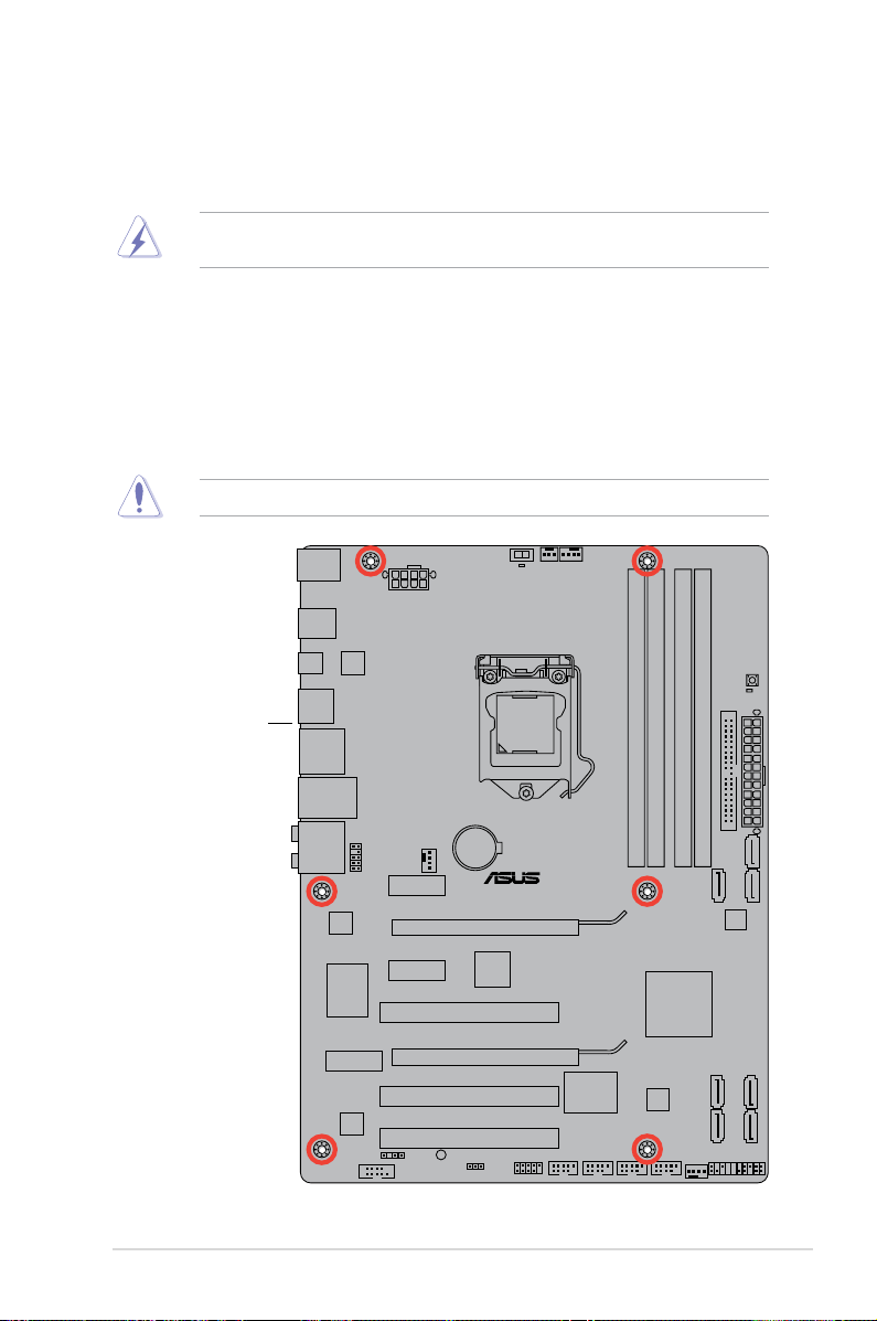
1.5.2 Screw holes
Place six screws into the holes indicated by circles to secure the motherboard to the chassis.
Do not overtighten the screws! Doing so can damage the motherboard.
Place this side towards
the rear of the chassis
1-7Chapter 1: Product introduction
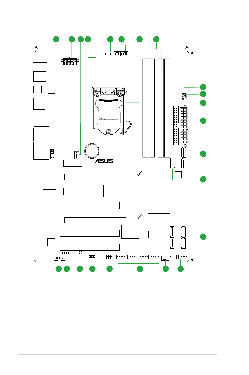
1.5.3 Motherboard layout
P8P67 LE
ASM
1042
PCIEX16_1
PCIEX16_2
PCIEX1_2
PCIEX1_1
PCI1
PCI2
PCI3
PRI_EIDE
USB78 USB910 USB1112 USB1314
PANEL
SPDIF_OUT
AAFP
EATXPWR
CHA_FAN1
CHA_FAN2
Lithium Cell
CMOS Power
Super
I/O
VIA
VT6308P
AUDIO
ALC
892
RTL
8111E
asmedia
ASM1085
COM1
KBMS
32Mb
BIOS
SB_PWR
CLRTC
22.4cm(8.8in)
30.5cm(12.0in)
Intel
®
P67
DDR3 DIMM_A1 (64bit, 240-pin module)
DDR3 DIMM_A2 (64bit, 240-pin module)
DDR3 DIMM_B1 (64bit, 240-pin module)
DDR3 DIMM_B2 (64bit, 240-pin module)
LAN1_USB12
F_ESATA6G
_USB34
SPDIF_O2
SATA3G_1
SATA3G_4
SATA6G_1
SATA6G_E1
LGA1155
EATX12V
USB3_12
USB56
MemOK!
DRAM_LED
SATA3G_3
SATA3G_2
IE1394_1
SATA6G_2
11
12
8
9
10
13
2
CPU_FAN
PWR_FAN
O2LED1
TPU
1 2 3 63 4 5 7
1431819 1720 1516
Marvell
SATA6G
ASUS P8P67 LE1-8
1.5.4 Layout contents
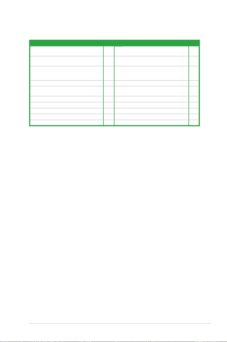
Connectors/Jumpers/Slots/LED Page Connectors/Jumpers/Slots/LED Page
1. Front panel audio connector (10-1 pin AAFP) 1-28 11. Marvell® Serial ATA 6.0Gb/s connector (7-pin
2. ATX power connectors (24-pin EATXPWR,
8-pin EATX12V)
3. CPU, chassis, and power fan connectors
(4-pin CPU_FAN, 4-pin CHA_FAN1/2,
3-pin PWR_FAN)
4. TPU LED (O2LED1) 1-38 14. System panel connector (20-8 pin PANEL) 1-35
5. TPU switch 1-36 15. USB connectors (10-1 pin USB78, USB910,
6. Intel® LGA1155 CPU socket 1-10 16. IEEE 1394a connector (10-1 pin IE1394_1) 1-28
7. DDR3 DIMM slots 1-15 17. Clear RTC RAM (3-pin CLRTC) 1-25
8. MemOK! switch 1-37 18. Onboard LED (SB_PWR) 1-38
9. DRAM LED (DRAM_LED) 1-38 19. Digital audio connector (4-1 pin SPDIF_OUT) 1-31
10. IDE connector (40-1 pin PRI_EIDE) 1-29 20. Serial port connector (10-1 pin COM1) 1-30
1-30 12. Intel® P67 Serial ATA 6.0Gb/s connectors
1-31 13. Intel® P67 Serial ATA 3.0Gb/s connectors
SATA6G_E1 [navy blue])
(7-pin SATA6G_1/2 [gray])
(7-pin SATA3G_1~4 [blue])
USB1112, USB1314)
1-34
1-32
1-33
1-36
1-9Chapter 1: Product introduction
1.6 Central Processing Unit (CPU)
A
B
P8P67 LE
P8P67 LE CPU socket LGA1155
The motherboard comes with a surface mount LGA1155 socket designed for the Intel®
Second Generation Core™ i7 / Core™ i5 / Core™ i3 processors.
Unplug all power cables before installing the CPU.
• Upon purchase of the motherboard, ensure that the PnP cap is on the socket and the
socket contacts are not bent. Contact your retailer immediately if the PnP cap is missing,
or if you see any damage to the PnP cap/socket contacts/motherboard components.
ASUS will shoulder the cost of repair only if the damage is shipment/transit-related.
• Keep the cap after installing the motherboard. ASUS will process Return Merchandise
Authorization (RMA) requests only if the motherboard comes with the cap on the
LGA1155 socket.
• The product warranty does not cover damage to the socket contacts resulting from
incorrect CPU installation/removal, or misplacement/loss/incorrect removal of the PnP
cap.
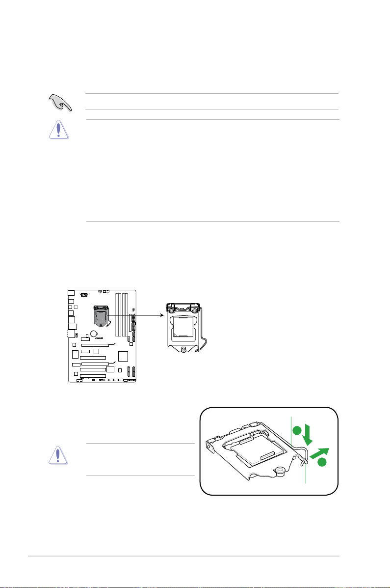
1.6.1 Installing the CPU
To install a CPU:
1. Locate the CPU socket on the motherboard.
2. Press the load lever with your thumb (A),
and then move it to the right (B) until it is
released from the retention tab.
To prevent damage to the socket pins,
do not remove the PnP cap unless
you are installing a CPU.
Load lever
Retention tab
ASUS P8P67 LE1-10
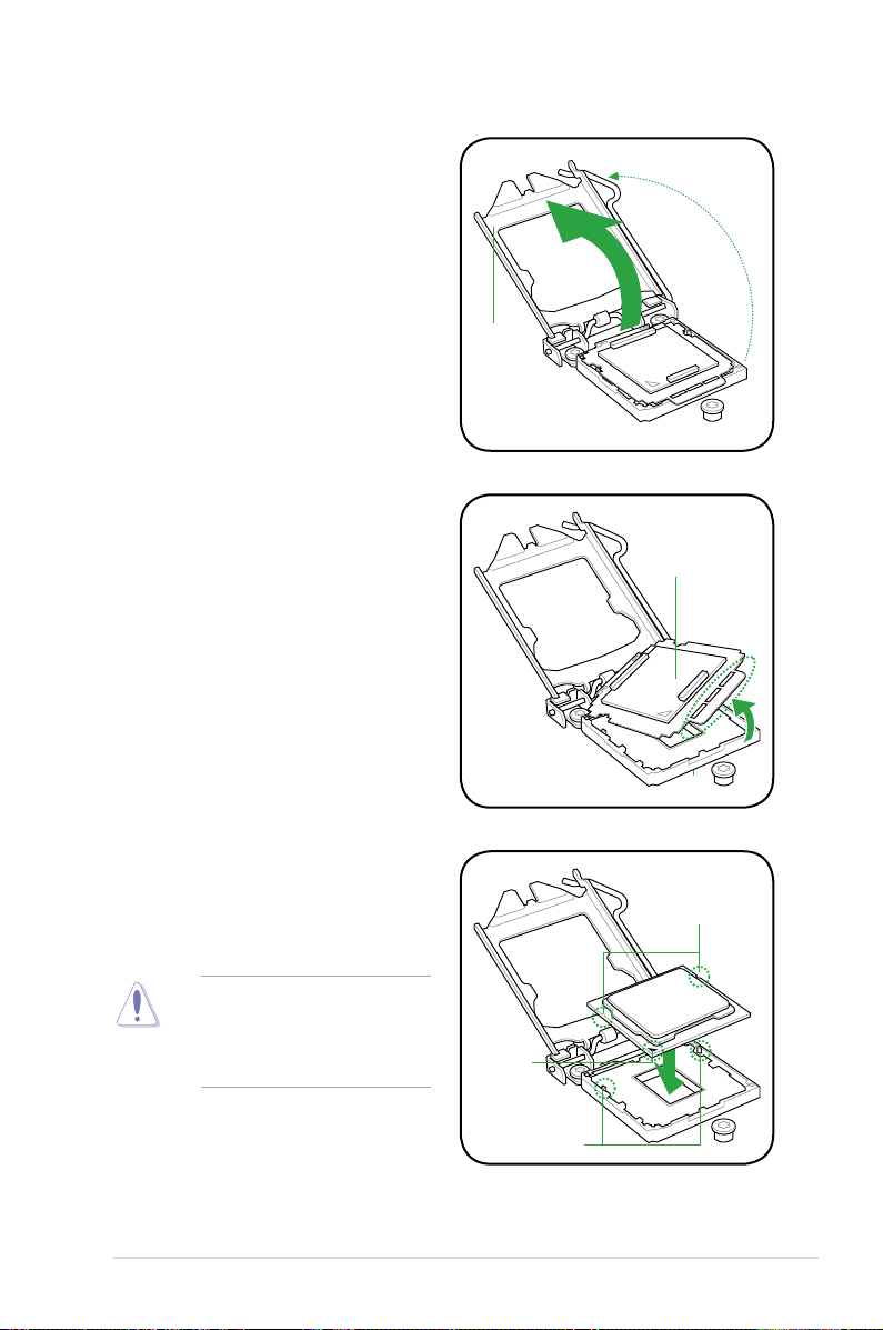
3. Lift the load lever in the direction of the
arrow until the load plate is completely
lifted.
4. Remove the PnP cap from the CPU
socket by lifting the tab only.
Load plate
PnP cap
5. Position the CPU over the socket,
ensuring that the gold triangle is on the
bottom-left corner of the socket, and
then t the socket alignment keys into
the CPU notches.
The CPU ts in only one correct
orientation. DO NOT force the CPU
into the socket to prevent bending
the connectors on the socket and
damaging the CPU!
CPU notches
Gold
triangle
mark
Alignment keys
1-11Chapter 1: Product introduction
B
A
C
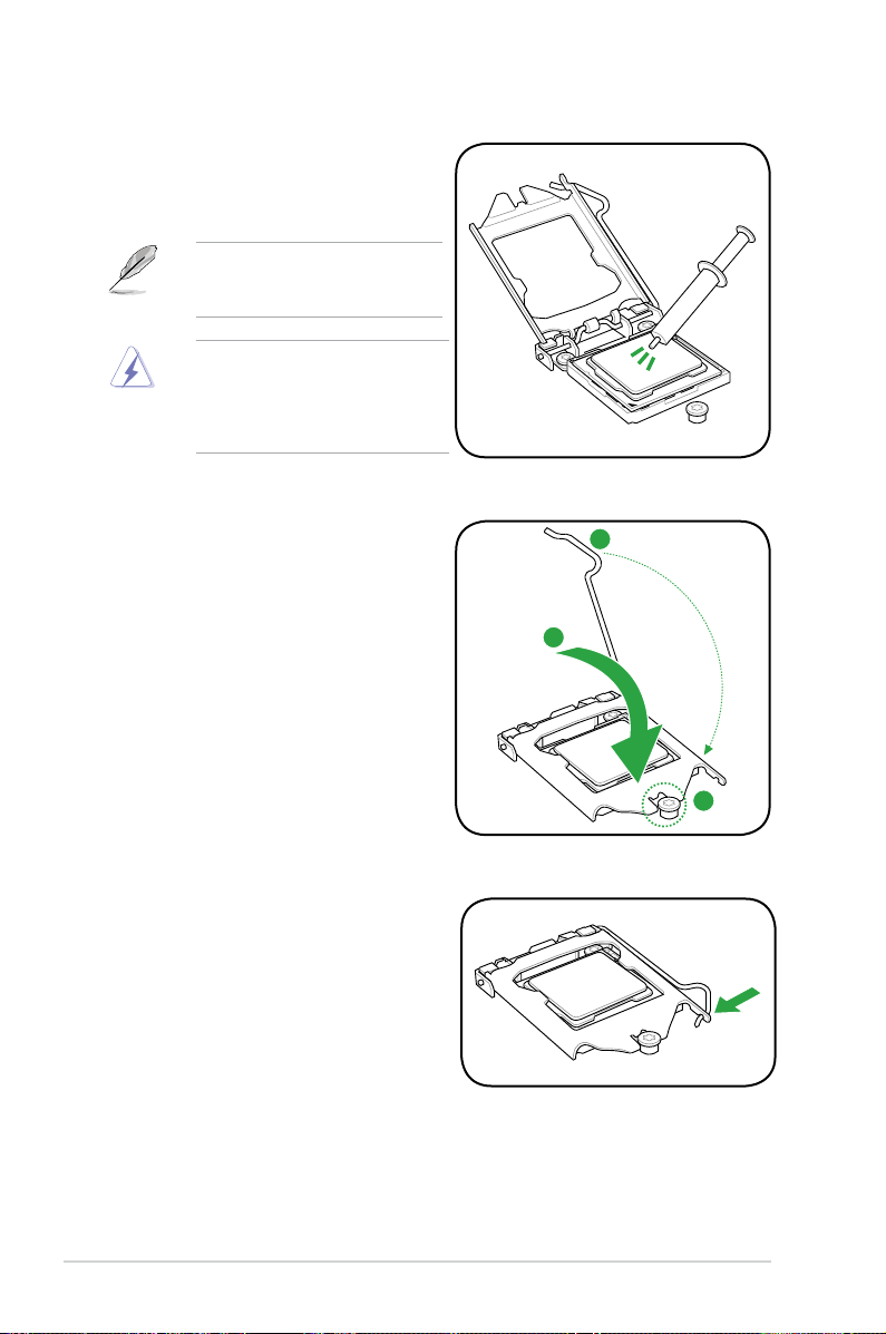
6. Apply some Thermal Interface Material
to the exposed area of the CPU that the
heatsink will be in contact with, ensuring
that it is spread in an even thin layer.
Some heatsinks come with preapplied thermal paste. If so, skip this
step.
The Thermal Interface Material is
toxic and inedible. DO NOT eat it. If
it gets into your eyes or touches your
skin, wash it off immediately, and seek
professional medical help.
7. Close the load plate (A), and then push
down the load lever (B), ensuring that
the front edge of the load plate slides
under the retention knob (C).
8. Insert the load lever under the retention
tab.
ASUS P8P67 LE1-12
1.6.2 Installing the CPU heatsink and fan
The Intel® LGA1155 processor requires a specially designed heatsink and fan assembly to
ensure optimum thermal condition and performance.
•
When you buy a boxed Intel® processor, the package includes the CPU fan and
heatsink assembly. If you buy a CPU separately, ensure that you use only Intel®-certied
multi-directional heatsink and fan.
• Your Intel
• Use an LGA1155-compatible CPU heatsink and fan assembly only. The LGA1155 socket
If you purchased a separate CPU heatsink and fan assembly, ensure that you have
properly applied Thermal Interface Material to the CPU heatsink or CPU before you install
the heatsink and fan assembly.
Ensure that you have installed the motherboard to the chassis before you install the CPU
fan and heatsink assembly.
®
LGA1155 heatsink and fan assembly comes in a push-pin design and
requires no tool to install.
is incompatible with the LGA775 and LGA1366 sockets in size and dimension.
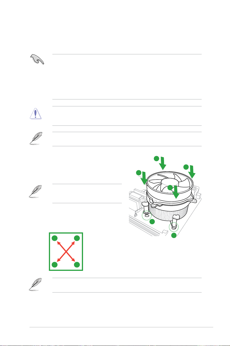
To install the CPU heatsink and fan:
1. Place the heatsink on top of the installed
CPU, ensuring that the four fasteners match
the holes on the motherboard.
Orient the heatsink and fan assembly
such that the CPU fan cable is closest to
the CPU fan connector.
2. Push down two fasteners at a time in a
diagonal sequence to secure the heatsink
and fan assembly in place.
A
B
The type of CPU heatsink and fan assembly may differ, but the installation steps and
functions should remain the same. The illustration above is for reference only.
B
A
A
B
B
A
1
1
1-13Chapter 1: Product introduction
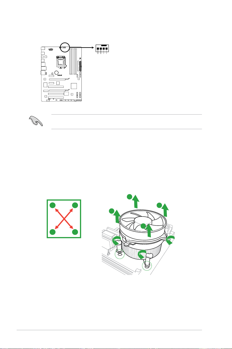
3. Connect the CPU fan cable to the connector on the motherboard labeled CPU_FAN.
CPU_FAN
CPU FAN PWM
CPU FAN IN
CPU FAN PWR
GND
P8P67 LE
P8P67 LE CPU fan connector
Do not forget to connect the CPU fan connector! Hardware monitoring errors can occur if
you fail to plug this connector.
1.6.3 Uninstalling the CPU heatsink and fan
To uninstall the CPU heatsink and fan:
1. Disconnect the CPU fan cable from the connector on the motherboard.
2. Rotate each fastener counterclockwise.
3. Pull up two fasteners at a time in a diagonal sequence to disengage the heatsink and
fan assembly from the motherboard.
A
A
B
B
B
B
A
A
ASUS P8P67 LE1-14
 Loading...