

Page 1

Motherboard
P5ND2
Page 2

ii
E2493
First Edition
April 2006
Copyright © 2006 ASUSTeK COMPUTER INC. All Rights Reserved.
No part of this manual, including the products and software described in it, may be reproduced,
transmitted, transcribed, stored in a retrieval system, or translated into any language in any form
or by any means, except documentation kept by the purchaser for backup purposes, without the
express written permission of ASUSTeK COMPUTER INC. (“ASUS”).
Product warranty or service will not be extended if: (1) the product is repaired, modied or
altered, unless such repair, modication of alteration is authorized in writing by ASUS; or (2)
the serial number of the product is defaced or missing.
ASUS PROVIDES THIS MANUAL “AS IS” WITHOUT WARRANTY OF ANY KIND, EITHER
EXPRESS OR IMPLIED, INCLUDING BUT NOT LIMITED TO THE IMPLIED WARRANTIES
OR CONDITIONS OF MERCHANTABILITY OR FITNESS FOR A PARTICULAR PURPOSE.
IN NO EVENT SHALL ASUS, ITS DIRECTORS, OFFICERS, EMPLOYEES OR AGENTS BE
LIABLE FOR ANY INDIRECT, SPECIAL, INCIDENTAL, OR CONSEQUENTIAL DAMAGES
(INCLUDING DAMAGES FOR LOSS OF PROFITS, LOSS OF BUSINESS, LOSS OF USE
OR DATA, INTERRUPTION OF BUSINESS AND THE LIKE), EVEN IF ASUS HAS BEEN
ADVISED OF THE POSSIBILITY OF SUCH DAMAGES ARISING FROM ANY DEFECT OR
ERROR IN THIS MANUAL OR PRODUCT.
SPECIFICATIONS AND INFORMATION CONTAINED IN THIS MANUAL ARE FURNISHED
FOR INFORMATIONAL USE ONLY, AND ARE SUBJECT TO CHANGE AT ANY TIME
WITHOUT NOTICE, AND SHOULD NOT BE CONSTRUED AS A COMMITMENT BY
ASUS. ASUS ASSUMES NO RESPONSIBILITY OR LIABILITY FOR ANY ERRORS OR
INACCURACIES THAT MAY APPEAR IN THIS MANUAL, INCLUDING THE PRODUCTS
AND SOFTWARE DESCRIBED IN IT.
Products and corporate names appearing in this manual may or may not be registered
trademarks or copyrights of their respective companies, and are used only for identication or
explanation and to the owners’ benet, without intent to infringe.
Page 3

iii
Contents
Notices ................................................................................................ vi
Safety information ..............................................................................vii
About this guide .................................................................................viii
P5ND2 specications summary ............................................................ x
Chapter 1: Product introduction
1.1 Welcome! .............................................................................. 1-2
1.2 Package contents .................................................................
1-2
1.3 Special features ....................................................................
1-3
1.3.1 Product highlights ...................................................
1-3
1.3.2 Innovative ASUS features .......................................
1-5
1.4 Before you proceed ..............................................................
1-6
1.5 Motherboard overview ..........................................................
1-7
1.5.1 Placement direction ................................................
1-7
1.5.2 Screw holes .............................................................
1-7
1.5.3 Motherboard layout ................................................
1-8
1.6 Central Processing Unit (CPU) ..............................................
1-9
1.6.1 Installing the CPU ....................................................
1-9
1.6.2 Installing the CPU heatsink and fan .........................
1-9
1.6.3 Uninstalling the CPU heatsink and fan ...................
1-14
1.7 System memory ..................................................................
1-16
1.7.1 Overview ...............................................................
1-16
1.7.2 Memory congurations .........................................
1-16
1.7.3 Installing a DIMM ...................................................
1-20
1.7.4 Removing a DIMM ..................................................
1-20
1.8 Expansion slots ...................................................................
1-21
1.8.1 Installing an expansion card ..................................
1-21
1.8.2 Conguring an expansion card ..............................
1-21
1.8.3 Interrupt assignments ...........................................
1-22
1.8.4 PCI slots ................................................................
1-23
1.8.5 PCI Express x1 slot ...............................................
1-23
1.8.6 PCI Express x16 slot .............................................
1-23
1.9 Jumpers ..............................................................................
1-24
1.10 Connectors .........................................................................
1-26
1.10.1 Rear panel connectors ..........................................
1-26
1.10.2 Internal connectors ...............................................
1-27
Page 4

iv
Contents
Chapter 2: BIOS setup
2.1 Managing and updating your BIOS ........................................ 2-2
2.1.1 Creating a bootable oppy disk ..............................
2-2
2.1.2 Updating the BIOS ...................................................
2-3
2.1.3 Saving the current BIOS le ....................................
2-5
2.1.4 ASUS CrashFree BIOS 2 utility ................................
2-6
2.1.5 ASUS EZ Flash utility ...............................................
2-8
2.1.6 ASUS Update utility ................................................
2-9
2.2 BIOS setup program ............................................................
2-12
2.2.1 BIOS menu screen .................................................
2-13
2.2.2 Menu bar ...............................................................
2-13
2.2.3 Legend bar ............................................................
2-14
2.2.4 Menu items ...........................................................
2-14
2.2.5 Sub-menu items ....................................................
2-14
2.2.6 Conguration elds ...............................................
2-14
2.2.7 Pop-up window ......................................................
2-15
2.2.8 General help ..........................................................
2-15
2.3 Main menu ...........................................................................
2-16
2.3.1 System Time ........................................................
2-16
2.3.2 System Date .......................................................
2-16
2.3.3 Legacy Diskette A ..............................................
2-16
2.3.4 Primary and Secondary IDE Master/Slave .............
2-17
2.3.5 First, Second, Third, Fourth SATA Master ............
2-19
2.3.6 HDD SMART Monitoring .........................................
2-20
2.3.7 Installed Memory ...................................................
2-20
2.3.8 Usable Memory ......................................................
2-20
2.4 Advanced menu ..................................................................
2-21
2.4.1 JumperFree Conguration .....................................
2-21
2.4.2 CPU Conguration .................................................
2-26
2.4.3 Chipset ..................................................................
2-28
2.4.4 PCIPnP ...................................................................
2-30
2.4.5 Onboard Devices Conguration .............................
2-30
2.4.6 USB Conguration .................................................
2-34
2.5 Power menu ........................................................................
2-35
2.5.1 ACPI Suspend Type .............................................
2-35
2.5.2 ACPI APIC Support ..............................................
2-35
Page 5

v
Contents
2.5.3 APM Conguration ................................................2-36
2.5.4 Hardware Monitor ..................................................
2-38
2.6 Boot menu ..........................................................................
2-39
2.6.1 Boot Device Priority ..............................................
2-39
2.6.2 Removable Drives ..................................................
2-40
2.6.3 Boot Settings Conguration ................................
2-40
2.6.4 Security .................................................................
2-42
2.7 Exit menu ............................................................................
2-44
Chapter 3:Software Support
3.1 Installing an operating system .............................................. 3-2
3.2 Support CD information ........................................................
3-2
3.2.1 Runninig the support CD .......................................................
3-2
3.2.2 Drivers menu .........................................................................
3-3
3.2.3 Utilities menu ........................................................................
3-4
3.2.4 Make Disk menu ....................................................................
3-5
3.2.5 Manuals menu .......................................................................
3-6
3.2.6 ASUS Contact information ....................................................
3-7
Page 6
vi
Notices
Fe de ra l Co mm un ic at io ns C om mi ss io n St at em en t
This device complies with Part 15 of the FCC Rules. Operation is subject to
the following two conditions:
•
This device may not cause harmful interference, and
•
This device must accept any interference received including interference
that may cause undesired operation.
This equipment has been tested and found to comply with the limits for a
Class B digital device, pursuant to Part 15 of the FCC Rules. These limits
are designed to provide reasonable protection against harmful interference
in a residential installation. This equipment generates, uses and can radiate
radio frequency energy and, if not installed and used in accordance with
manufacturer’s instructions, may cause harmful interference to radio
communications. However, there is no guarantee that interference will
not occur in a particular installation. If this equipment does cause harmful
interference to radio or television reception, which can be determined by
turning the equipment off and on, the user is encouraged to try to correct
the interference by one or more of the following measures:
•
Reorient or relocate the receiving antenna.
•
Increase the separation between the equipment and receiver.
•
Connect the equipment to an outlet on a circuit different from that to
which the receiver is connected.
•
Consult the dealer or an experienced radio/TV technician for help.
Ca na di an D ep ar tm en t of C om mu ni ca ti on s St at em en t
This digital apparatus does not exceed the Class B limits for radio noise
emissions from digital apparatus set out in the Radio Interference
Regulations of the Canadian Department of Communications.
This class B digital apparatus complies with Canadian ICES-003.
The use of shielded cables for connection of the monitor to the graphics
card is required to assure compliance with FCC regulations. Changes
or modications to this unit not expressly approved by the party
responsible for compliance could void the user’s authority to operate
this equipment.
Page 7
vii
Safety information
El ec tr ic al s af et y
•
To prevent electrical shock hazard, disconnect the power cable from
the electrical outlet before relocating the system.
•
When adding or removing devices to or from the system, ensure that
the power cables for the devices are unplugged before the signal
cables are connected. If possible, disconnect all power cables from the
existing system before you add a device.
•
Before connecting or removing signal cables from the motherboard,
ensure that all power cables are unplugged.
•
Seek professional assistance before using an adpater or extension
cord. These devices could interrupt the grounding circuit.
•
Make sure that your power supply is set to the correct voltage in your
area. If you are not sure about the voltage of the electrical outlet you
are using, contact your local power company.
•
If the power supply is broken, do not try to x it by yourself. Contact
a qualied service technician or your retailer.
Op er at io n sa fe ty
•
Before installing the motherboard and adding devices on it, carefully
read all the manuals that came with the package.
•
Before using the product, make sure all cables are correctly connected
and the power cables are not damaged. If you detect any damage,
contact your dealer immediately.
•
To avoid short circuits, keep paper clips, screws, and staples away from
connectors, slots, sockets and circuitry.
•
Avoid dust, humidity, and temperature extremes. Do not place the
product in any area where it may become wet.
•
Place the product on a stable surface.
•
If you encounter technical problems with the product, contact a
qualied service technician or your retailer.
The symbol of the crossed out wheeled bin indicates that the product
(electrical and electronic equipment) should not be placed in municipal
waste. Check local regulations for disposal of electronic products.
Page 8
viii
About this guide
This user guide contains the information you need when installing and
conguring the motherboard.
Ho w th is g ui de i s or ga ni ze d
This guide contains the following parts:
• Chapter 1: Product introduction
This chapter describes the features of the motherboard and the new
technology it supports.
• Chapter 2: BIOS setup
This chapter tells how to change system settings through the BIOS
Setup menus. Detailed descriptions of the BIOS parameters are also
provided.
• Chapter 3: Software support
This chapter describes the contents of the support CD that comes
with the motherboard package.
Wh er e to f in d mo re i nf or ma ti on
Refer to the following sources for additional information and for product
and software updates.
1. ASU S web s i tes
The ASUS website provides updated information on ASUS hardware
and software products. Refer to the ASUS contact information.
2. Opt i o nal d ocu m e nta t i on
Your product package may include optional documentation, such as
warranty yers, that may have been added by your dealer. These
documents are not part of the standard package.
Page 9
ix
Co nv en ti on s us ed i n th is g ui de
To make sure that you perform certain tasks properly, take note of the
following symbols used throughout this manual.
Ty po gr ap hy
Bol d tex t Indicates a menu or an item to select.
Italics
Used to emphasize a word or a phrase.
<Key> Keys enclosed in the less-than and greater-than
sign means that you must press the enclosed
key.
Example: <Enter> means that you must press
the Enter or Return key.
<Key1>+<Key2>+<Key3> If you must press two or more keys
simultaneously, the key names are linked with
a plus sign (+).
Example: <Ctrl>+<Alt>+<D>
Command
Means that you must type the command
exactly as shown, then supply the required
item or value enclosed in brackets.
Example: At the DOS prompt, type the
command line:
afudos /i[lename]
afudos /iP5ND2.ROM
DAN G E R/W A R NIN G : Information to prevent injury to yourself
when trying to complete a task.
CAU T I ON: Information to prevent damage to the components
when trying to complete a task.
NOT E : Tips and additional information to help you complete a
task.
I
MPO R T ANT : Instructions that you MUST follow to complete a
task.
Page 10
x
P5ND2 specications summary
(continued on the next page)
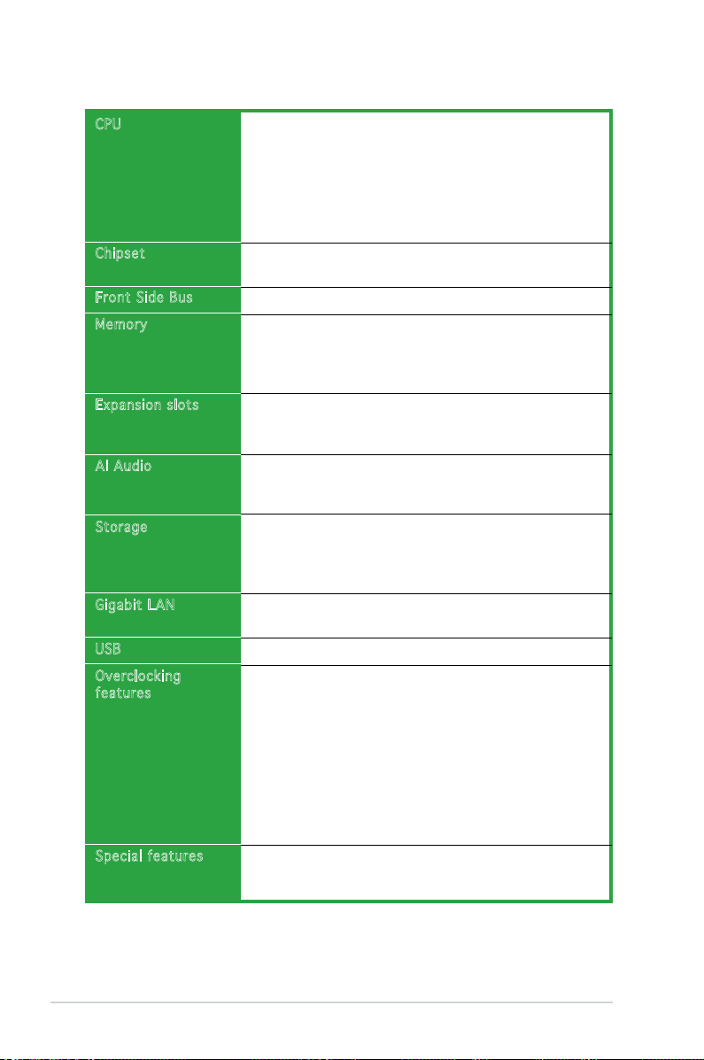
CPU
Chipset
Front Side Bus
Memory
Expansion slot s
AI Audio
Storage
Gigabit LAN
USB
Overclocking
features
Special featur es
LGA775 socket for Intel® Pentium® D/Intel® Pentium® 4/
Intel
®
Celeron® processors
Compatible with Intel® PCG 05B/05A and 04B/04A
processors
Supports Intel® Dual-core Technology
Supports Enhanced Intel SpeedStep® Technology (EIST)
Supports Intel® Hyper-Threading Technology
Northbridge: NVIDIA® C19
Southbridge: NVIDIA® MCP51
800/533 MHz
Dual-channel memory architecture
4 x 240-pin DIMM sockets support unbufferred non-ECC
DDR2 667/533 memory modules
Supports up to 16 GB system memory
1 x PCI Express x16 slot for discrete graphics card
3 x PCI Express x1 slots
2 x PCI slots
ADI® AD1986A 6-channel CODEC
1 x Coaxial S/PDIF out port
Supports Jack Sensing and Enumeration Technology
NVIDIA® MCP51 chipset supports:
- 2 x Ultra DMA 133/100/66
- 4 x Serial ATA 3Gb/s devices
- RAID 0, RAID 1, RAID 0+1, RAID 5 and JBOD
Realtek® RTL8111B Gigabit LAN controller
- AI NET
Supports up to 8 USB 2.0 ports
CPU Lock Free
ASUS AI Overclocking (Intelligent Frequency Tuner)
Precision Tweaker supports:
- DIMM voltage: 4-step DRAM voltage control
- Core voltage: Adjustable CPU voltage at 0.0125 V
- Stepless Frequency Selection (SFS) allows FSB
tuning from 133MHz to 400 MHz at 1MHz
increment
Adjustable FSB/DDR2/PCIe frequencies with xed 33Hz
PCI frequencies
ASUS CrashFree BIOS 2
ASUS MyLogo2
ASUS EZ Flash
Page 11
xi
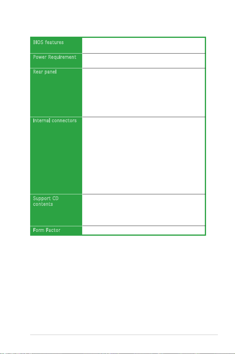
4 MB Flash ROM, Award BIOS, PnP, DMI2.0, SM BIOS 2.3,
WfM2.0, ASUS EZ Flash, ASUS CrashFree BIOS2
ATX power supply (with 24-pin and 4-pin 12V plugs)
ATX 12V 2.0 compliant
1 x Parallel port
1 x Serial port
1 x LAN (RJ-45) ports
USB 2.0 ports
1 x Coaxial S/PDIF Out port
1 x PS/2 keyboard port
1 x PS/2 mouse port
6-channel audio ports
1 x Floppy disk drive connector
2 x IDE connectors
4 x Serial ATA connectors
1 x 24-pin ATX power connector
1 x 4-pin ATX 12 V power connector
2 x USB connectors for additional four USB 2.0 ports
1 x S/PDIF connector
2 x Internal audio connectors (CD, AUX)
1 x GAME connector
1 x Chassis intrusion connector
1 x Front panel audio connector
CPU, Chassis, Power fan connectors
System panel connector
Device drivers
ASUS PC Probe II
ASUS Update
ASUS Screen saver
Anti-Virus software
ATX form factor: 12 in x 8 in
BIOS features
Power Requirem ent
Rear panel
Internal conne ctors
Support CD
contents
Form Factor
P5ND2 specications summary
* Specications are subject to change without notice.
Page 12

xii
Page 13

ASUS P5ND2 1-1
1
Product
introduction
This chapter describes the motherboard
features and the new technologies
it supports.
Page 14
1-2 Chapter 1: Product introduction
1.1 Welcome!
T h a n k y o u f o r b u y i n g a n A S U S® P 5 N D 2 m o t h e r b o a r d !
The motherboard delivers a host of new features and latest technologies,
making it another standout in the long line of ASUS quality motherboards!
Before you start installing the motherboard, and hardware devices on it,
check the items in your package with the list below.
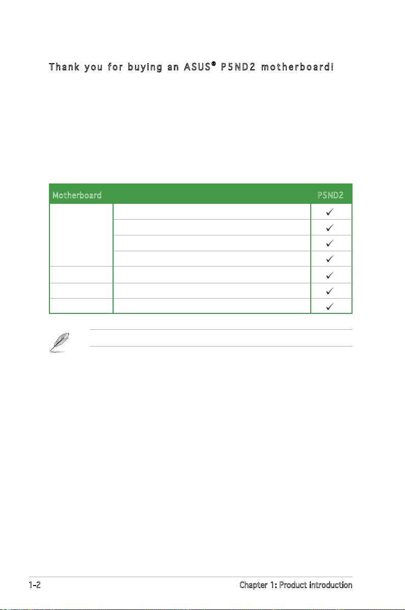
1.2 Package contents
Check your motherboard package for the following items.
If any of the above items is damaged or missing, contact your retailer.
Motherboard P5ND2
Cables 1 x Serial ATA cable set
1 x Ultra DMA 133/100/66 cable
40-conductor IDE cable
Floppy disk drive cable
Accessories
I/O shield
Application CD ASUS motherboard support CD
Documentation User guide
Page 15
ASUS P5ND2 1-3
1.3 Special features
1. 3. 1 Pr od uc t hi gh li gh ts
Lat est p r oc e ss o r tec hno lo g y
The motherboard comes with a 775-pin surface mount Land Grid Array (LGA)
socket designed for the Intel® Pentium® D, Intel® Pentium® 4, and Intel®
Celeron® processors in the 775-land package. The motherboard supports
Intel® processors with 800/533 MHz Front Side Bus (FSB). The motherboard
also supports the Intel® Hyper-Threading Technology, Intel® Dual-Core
Technology and is fully compatible with Intel® 05B/05A and 04B/04A
processors. See page 1-9 for details.
Int el® Du al- Co r e T ec h no log y C PU su p po r t
The motherboard supports dual-core processors containing two physical
CPU cores with dedicated L2 caches to meet demands for more powerful
processing.
Enh anc ed In t el Sp eed Ste p® Te chn ol o gy (E I ST )
The Enhanced Intel SpeedStep® Technology (EIST) intelligently manages
the CPU resources by automatically adjusting the CPU voltage and core
frequency depending on the CPU loading and system speed or power
requirement.
Dua l-c ha n ne l D D R2 me mor y s up p or t
The motherboard supports DDR2 memory for exible system upgrade and
to meet the higher bandwidth requirements of the latest 3D graphics,
multimedia, and Internet applications. The dual-channel architecture allows
memory bandwidths of up to 8.5 GB/s for DDR2. See page 1-16 for details.
PCI Ex pr e ss ™ i n te rfa ce
The motherboard fully supports PCI Express, the latest I/O interconnect
technology that speeds up the PCI bus. PCI Express features point-to-point
serial interconnections between devices and allows higher clockspeeds by
carrying data in packets. This high speed interface is software compatible
with existing PCI specications. See pages 1-23 for details.
Page 16
1-4 Chapter 1: Product introduction
CPU Lo ck Fr e e
This feature allows you to adjust the CPU multiplier to 14x. Setting the
appropriate BIOS setting automatically reduces the CPU multiplier value for
more exibility when increasing external FSB.
USB 2. 0 t ec h no l og y
The motherboard implements the Universal Serial Bus (USB) 2.0
specication, dramatically increasing the connection speed from the
12 Mbps bandwidth on USB 1.1 to a fast 480 Mbps on USB 2.0. USB 2.0 is
backward compatible with USB 1.1. See pages 1-25 and 1-30 for details.
Ser ial A T A 3 Gb / s tec hno lo g y
The motherboard supports the Serial ATA 3 Gb/s technology through
the Serial ATA interfaces. The Serial ATA 3 Gb/s specication provides
twice the bandwidth of the current Serial ATA products with a host of
new features, including Native Command Queueing (NCQ), and Power
Management (PM) Implementation Algorithm. Serial ATA allows for thinner,
more exible cables with lower pin count, reduced voltage requirement. See
page 1-29 for details.
Page 17
ASUS P5ND2 1-5
1. 3. 2 In no va ti ve A SU S fe at ur es
Pre cis io n T w ea k er
This feature allows you to ne tune the CPU/memory voltage and gradually
increase the memory Front Side Bus (FSB) and PCI Express frequency at
1MHz increment to achieve maximum system performance.
Fan les s D es i gn
The ASUS fanless design allows multi-directional heat ow from major
thermal sources in the motherboard to lower overall system temperature,
resulting in quieter operation and longer system life.
Cra shF re e B I OS 2
This feature allows you to restore the original BIOS data from the support CD
in case when the BIOS codes and data are corrupted. This protection eliminates
the need to buy a replacement ROM chip. See page 2-6 for details.
ASU S M yL o go 2 ™
This new feature present in the motherboard allows you to personalize and
add style to your system with customizable boot logos. See page 2-41 for
details.
Page 18
1-6 Chapter 1: Product introduction
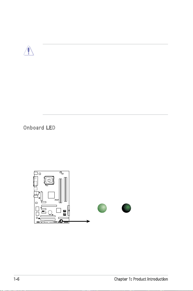
Onb oar d L ED
The motherboard comes with a standby power LED. The green LED
lights up to indicate that the system is ON, in sleep mode, or in softoff mode. This is a reminder that you should shut down the system
and unplug the power cable before removing or plugging in any
motherboard component. The illustration below shows the location of
the onboard LED.
1.4 Before you proceed
Take note of the following precautions before you install motherboard
components or change any motherboard settings.
• Unplug the power cord from the wall socket before touching any
component.
• Use a grounded wrist strap or touch a safely grounded object or to
a metal object, such as the power supply case, before handling
components to avoid damaging them due to static electricity.
• Hold components by the edges to avoid touching the ICs on them.
• Whenever you uninstall any component, place it on a grounded
antistatic pad or in the bag that came with the component.
• Before you install or remove any component, ensure
that the ATX power supply is switched off or the power cord is
detached from the power supply. Failure to do so may cause severe
damage to the motherboard, peripherals, and/or components.
P5ND2
R
SB_PWR
ON
Standby
Power
OFF
Powered
Off
P5ND2 Onboard LED
Page 19
ASUS P5ND2 1-7
P5ND2
R
1.5 Motherboard overview
Before you install the motherboard, study the conguration of your chassis
to ensure that the motherboard ts into it.
Make sure to unplug the power cord before installing or removing the
motherboard. Failure to do so can cause you physical injury and damage
motherboard components.
Do not overtighten the screws! Doing so can damage the motherboard.
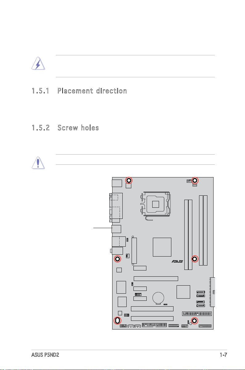
1. 5. 1 Pl ac em en t di re ct io n
When installing the motherboard, make sure that you place it into the
chassis in the correct orientation. The edge with external ports goes to the
rear part of the chassis as indicated in the image below.
1. 5. 2 Sc re w ho le s
Place six (6) screws into the holes indicated by circles to secure the
motherboard to the chassis.
Place this side towards
the rear of the chassis
Page 20
1-8 Chapter 1: Product introduction
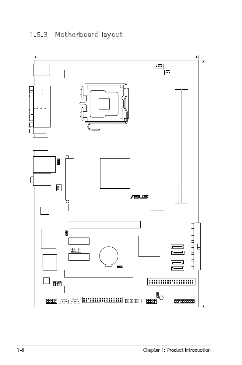
1. 5. 3 Mo th er bo ar d la yo ut
LGA775
DDR2 DIMM_A1 (128 bit,240-pin module)
DDR2 DIMM_A2 (128 bit,240-pin module)
DDR2 DIMM_B1 (128 bit,240-pin module)
DDR2 DIMM_B2 (128 bit,240-pin module)
PCI1
PCI2
PCIEX16
PCIEX1_1
PCIEX1_2
PCIEX1_3
CR2032 3V
Lithium Cell
CMOS Power
4Mb
BIOS
Super I/O
SEC_IDE
PRI_IDE
nVIDIA
Crush19
MCP51
SATA1
SATA2
SATA3
SATA4
AD1986A
RTL8111B
EATXPWR
PWR_FAN
CPU_FAN
ATX12V
CHA_FAN
P5ND2
R
PANEL
USB56
FLOPPY
SB_PWR
AAFP
CD AUX
SPDIF_OUT
CHASSIS
USB78
CLRTC
USBPW1234
USBPW78
USBPW56
GAME
USB12
Below:Mic In
Center:Line Out
Top:Line In
PS/2KBMS
T: Mouse
B: Keyboard
COM1
PARALLEL PORT
RJ-45
Top:
USB3
USB4
Bottom:
SPDIF_O1
30.5cm (12.0in)
19.6cm (8.0in)
Page 21
ASUS P5ND2 1-9
1.6 Central Processing Unit (CPU)
The motherboard comes with a surface mount LGA775 socket designed for
the Intel® Pentium® D, Intel® Pentium® 4 and Intel® Celeron® processors in
the 775-land package.
•
Install a chassis fan with at least a speed of 2400 rpm and 8 CFM
turnrate when using a dual-core CPU to ensure system stability.
Overheating can permanently damage the system and/or CPU.
• Upon purchase of the motherboard, make sure that the PnP cap is
on the socket and the socket contacts are not bent. Contact your
retailer immediately if the PnP cap is missing, or if you see any
damage to the PnP cap/socket contacts/motherboard components.
ASUS will shoulder the cost of repair only if the damage is shipment/
transit-related.
•
Keep the cap after installing the motherboard. ASUS will process
Return Merchandise Authorization (RMA) requests only if the
motherboard comes with the cap on the LGA775 socket.
• The product warranty does not cover damage to the socket contacts
resulting from incorrect CPU installation/removal, or misplacement/
loss/incorrect removal of the PnP cap.
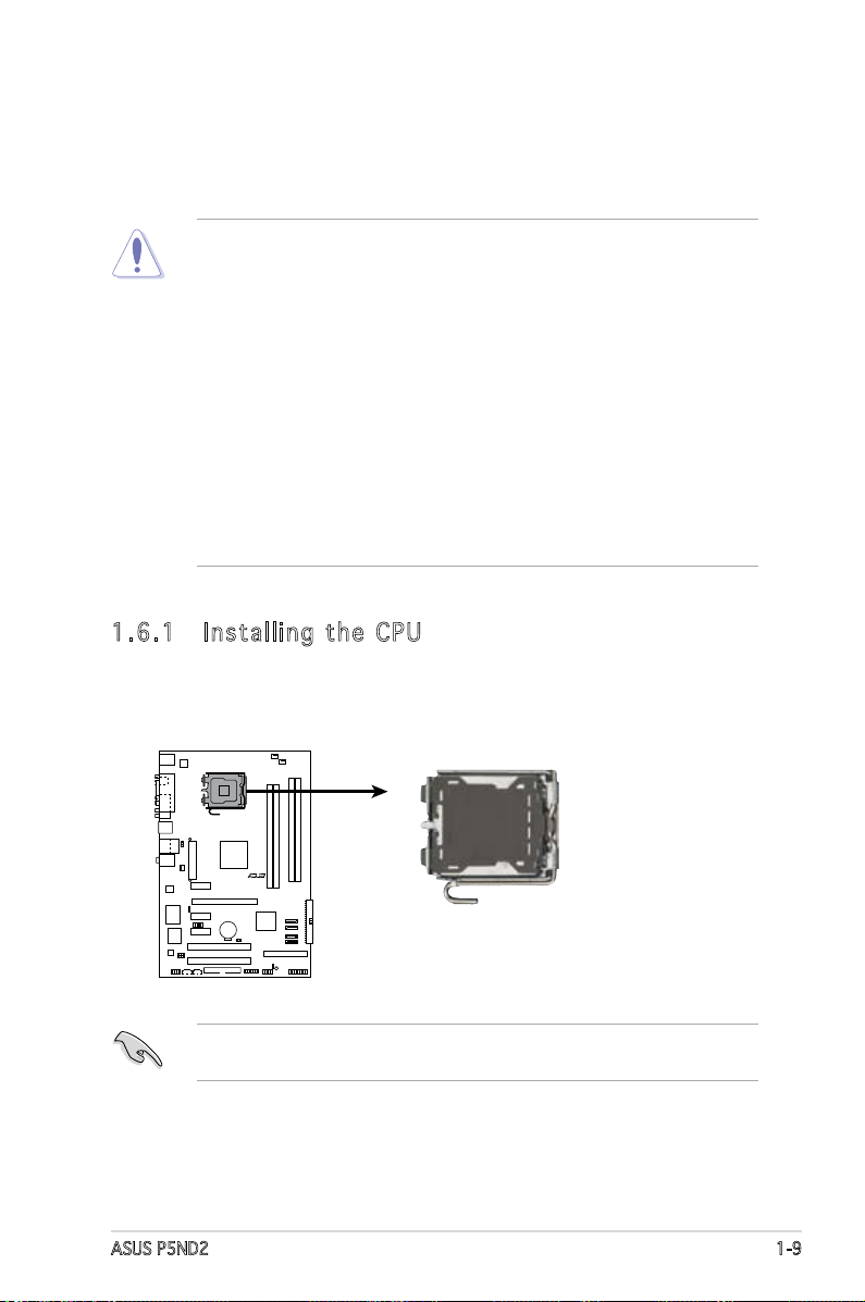
1. 6. 1 In st al li ng t he C PU
To install a CPU:
1. Locate the CPU socket on the motherboard.
Before installing the CPU, make sure that the cam box is facing towards
you and the load lever is on your left.
P5ND2
R
P5ND2 CPU Socket 775
Page 22
1-10 Chapter 1: Product introduction
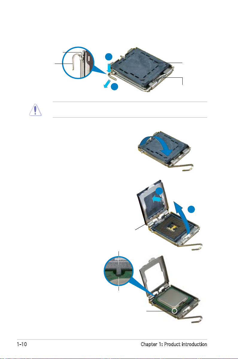
2. Press the load lever with your thumb (A), then move it to the left (B)
until it is released from the retention tab.
Retention tab
Load lever
This side of the socket
box should face you.
PnP cap
A
B
To prevent damage to the socket pins, do not remove the PnP cap
unless you are installing a CPU.
3. Lift the load lever in the direction
of the arrow to a 135º angle.
4. Lift the load plate with your
thumb and forenger to a 100º
angle (A), then push the PnP cap
from the load plate window to
remove (B).
5. Position the CPU over
the socket, making sure
that the gold triangle
is on the bottom-left
corner of the socket.
The socket alignment
key should t into the
CPU notch.
CPU notch
Gold triangle mark
Load plate
A
B
Alignment key
Page 23
ASUS P5ND2 1-11
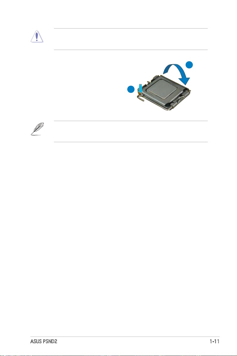
The CPU ts in only one correct orientation. DO NOT force the CPU
into the socket to prevent bending the connectors on the socket and
damaging the CPU!
6. Close the load plate (A), then
push the load lever (B) until it
snaps into the retention tab.
A
B
The motherboard supports Intel® Pentium® 4 LGA775 processors with
the Enhanced Intel SpeedStep® Technology (EIST), and Hyper-Threading
Technology.
Page 24
1-12 Chapter 1: Product introduction
Fastener
Motherboard hole
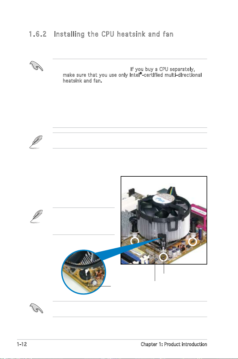
1. 6. 2 In st al li ng t he C PU h ea ts in k an d fa n
Intel® LGA775 processors require a specially designed heatsink and fan
assembly to ensure optimum thermal condition and performance.
To install the CPU heatsink and fan:
1. Place the heatsink on top of the
installed CPU, making sure that
the four fasteners match the
holes on the motherboard.
Narrow end
of the groove
•
When you buy a boxed Intel® processor, the package includes the
CPU fan and heatsink assembly. If you buy a CPU separately,
make sure that you use only Intel®-certified mul ti-directional
heatsink and f an.
•
Your Intel® LGA775 processor heatsink and fan assembly comes in a
push-pin design and requires no tool to install.
•
If you purchased a separate CPU heatsink and fan assembly, make
sure that you have properly applied Thermal Interface Material to
the CPU heatsink or CPU before you install the heatsink and fan
assembly.
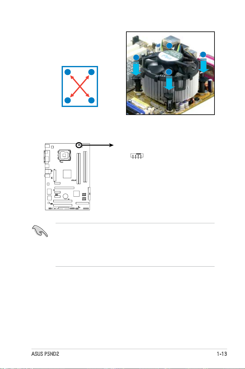
Make sure that you have installed the motherboard to the chassis before
you install the CPU fan and heatsink assembly.
Make sure to orient each fastener with the narrow end of the groove
pointing outward. (The photo shows the groove shaded for emphasis.)
Orient the heatsink and fan
assembly such that the CPU
fan cable is closest to the
CPU fan connector.
Page 25
ASUS P5ND2 1-13
3. Connect the CPU fan cable to the connector on the motherboard
labeled CPU_FAN.
2. Push down two fasteners at
a time in a diagonal sequence
to secure the heatsink and fan
assembly in place.
B
B
A
A
A
A
B
B
• Do not forget to connect the CPU fan connector! Hardware
monitoring errors can occur if you fail to plug this connector.
• The retention module of some third-party CPU heatsink and fan
can interfere with chipset components at the bottom of the board.
Before purchasing a separate CPU heatsink and fan, make sure that
it will not interfere with the chipset components.
P5ND2
R
P5ND2
CPU Fan Connector
CPU_FAN
GND
CPU FAN PWR
CPU FAN IN
CPU FAN PWM
Page 26
1-14 Chapter 1: Product introduction
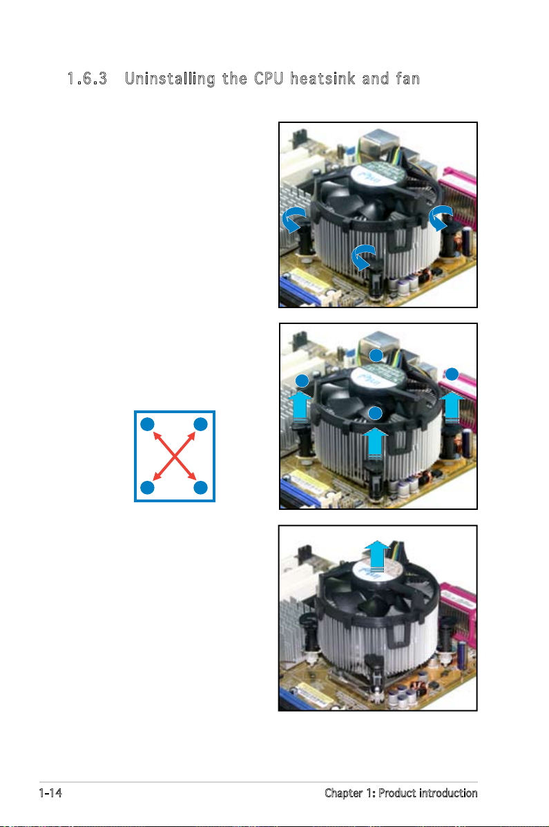
1. 6. 3 Un in st al li ng t he C PU h e a t s i n k a n d f a n
To uninstall the CPU heatsink and fan:
1. Disconnect the CPU fan cable
from the connector on the
motherboard.
2. Rotate each fastener
counterclockwise.
3. Pull up two fasteners at a
time in a diagonal sequence to
disengage the heatsink and fan
assembly from the motherboard.
B
A
B
A
A
A
B
B
4. Carefully remove the heatsink
and fan assembly from the
motherboard.
Page 27
ASUS P5ND2 1-15
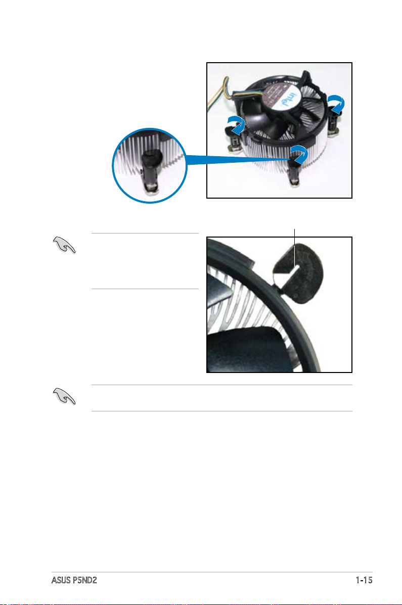
5. Rotate each fastener clockwise
to ensure correct orientation
when reinstalling.
The narrow end of the
groove should point outward
after resetting. (The photo
shows the groove shaded for
emphasis.)
Narrow end of the groove
Refer to the documentation in the boxed or stand-alone CPU fan package
for detailed information on CPU fan installation.
Page 28
1-16 Chapter 1: Product introduction
1.7 System memory
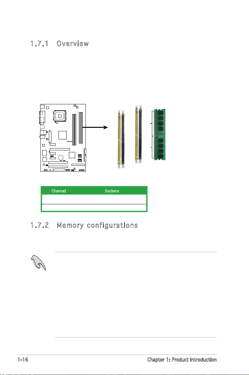
1. 7. 1 Ov er vi ew
The motherboard comes with four Double Data Rate 2 (DDR2) Dual Inline
Memory Modules (DIMM) sockets.
A DDR2 module has the same physical dimensions as a DDR DIMM but has
a 240-pin footprint compared to the 184-pin DDR DIMM. DDR2 DIMMs are
notched differently to prevent installation on a DDR DIMM socket.
The gure illustrates the location of the DDR2 DIMM sockets:
Cha nnel Soc kets
Channel A DIMM_A1 and DIMM_A2
Channel B DIMM_B1 and DIMM_B2
1. 7. 2 Me mo ry c on fi gu ra ti on s
You may install 256 MB, 512 MB, 1 GB, 2 GB and 4 GB unbuffered non-ECC
DDR2 DIMMs into the DIMM sockets.
• For dual-channel conguration, the total size of memory module(s)
installed per channel must be the same
(DIMM_A1 + DIMM_A2 = DIMM_B1 + DIMM_B2).
• Always install DIMMs with the same CAS latency. For optimum
compatibility, it is recommended that you obtain memory modules from
the same vendor. Refer to the DDR2 Qualied Vendors List on the next
page for details.
• If you install four 1GB memory modules, the system may only recognize
less than 3 GB because the address space is reserved for other critical
functions. This limitation appears on Windows® XP 32-bit operation
system which does not support Physical Address Extension (PAE).
• If you install Windows
®
XP 32-bit operation system, a total memory of
less than 3GB is recommended.
P5ND2
R
P5ND2
240-pin DDR2 DIMM Sockets
DIMM_B2
DIMM_A1
DIMM_A2
DIMM_B1
112 Pins128 Pins
Page 29
ASUS P5ND2 1-17
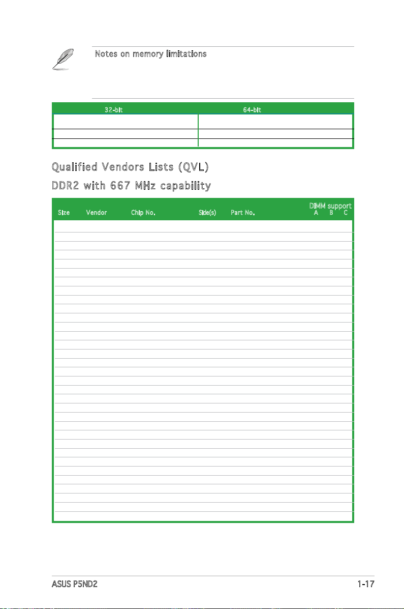
Notes on memor y limitations
The motherboard can support up to 16 GB on the operating systems
listed below. You may install a maximum of 2 GB DIMMs on each slot, but
only DDR2-533 2 GB density modules are available for this conguration.
32- bit 64- bit
Windows® 2000 Advanced Server Windows® Server 2003 Standard x64 Edition
Windows® Server 2003 Enterprise Edition Windows® XP Professional x64 Edition
Windows
®
Server 2003 Enterprise x64 Edition
Qua lif ie d V e nd o rs Li sts ( Q VL )
512MB KINGSTON E5108AE-6E-E SS KVR667D2N5/512 • • •
1024MB KINGSTON E5108AE-6E-E DS KVR667D2N5/1G • •
512MB KINGSTON E5108AE-6E-E SS KVR667D2E5/512 • • •
256MB KINGSTON HYB18T256800AF3 SS KVR667D2N5/256 • • •
256MB SAMSUNG K4T56083QF-ZCE6 SS M378T3253FZ0-CE6 • • •
512MB SAMSUNG K4T56083QF-ZCE6 DS M378T6453FZ0-CE6 • •
256MB SAMSUNG K4T51163QC-ZCE6 SS M378T3354CZ0-CE6 • • •
512MB SAMSUNG ZCE6K4T51083QC SS M378T6553CZ0-CE6 • • •
1024MB SAMSUNG ZCE6K4T51083QC DS M378T2953CZ0-CE6 • •
512MB MICRON 4VB41D9CZM DS MT16HTF6464AY-667B4 • • •
256MB Inneon HYB18T512160AF-3S SS HYS64T32000HU-3S-A • • •
512MB Inneon HYB18T512800AF3S SS HYS64T64000HU-3S-A • • •
1024MB Inneon HYB18T512800AF3S DS HYS64T128020HU-3S-A • •
512MB Hynix HY5PS12821AFP-Y5 SS HYMP564U64AP8-Y5 • •
1024MB Hynix HY5PS12821AFP-Y5 DS HYMP512U64AP8-Y5 • •
512MB Hynix HY5PS12821AFP-Y4 SS HYMP564U64AP8-Y4 • • •
1024MB Hynix HY5PS12821AFP-Y4 DS HYMP512U64AP8-Y4 • •
256MB ELPIDA E2508AB-GE-E SS EBE25UC8ABFA-6E-E • • •
512MB ELPIDA E5108AE-GE-E SS EBE51UD8AEFA-6E-E • • •
512MB crucial Heat-Sink Package DS BL6464AA664.16FB • •
1024MB crucial Heat-Sink Package DS BL12864AA664.16FA
•
512MB crucial Heat-Sink Package DS BL6464AL664.16FB • •
1024MB crucial Heat-Sink Package DS BL12864AL664.16FA • •
512MB Kingmax E5108AE-6E-E SS KLCC28F-A8EB5 • •
1024MB Kingmax E5108AE-6E-E DS KLCD48F-A8EB5 • •
1024MB Apacer E5108AE-6E-E DS 78.01092.420 • •
512MB A-DATA E5108AE-6E-E SS M20EL5G3H3160B1C0Z • • •
512MB TwinMOS E5108AE-GE-E SS 8G-25JK5-EBT • • •
512MB GEIL Heat-Sink Package SS GX21GB5300UDC • • •
512MB GEIL Heat-Sink Package SS GX21GB5300DC • •
256MB NANYA NT5TU32M16AG-3C SS NT256T64UH4A0FY-3C •
512MB NANYA NT5TU64M8AE-3C SS NT512T64U88A0BY-3C • •
512MB Elixir N2TU51280AF-3C SS M2U51264TU88A0F-3C • • •
Siz e V endor Chip No. Side(s) Part No. A B C
DIMM support
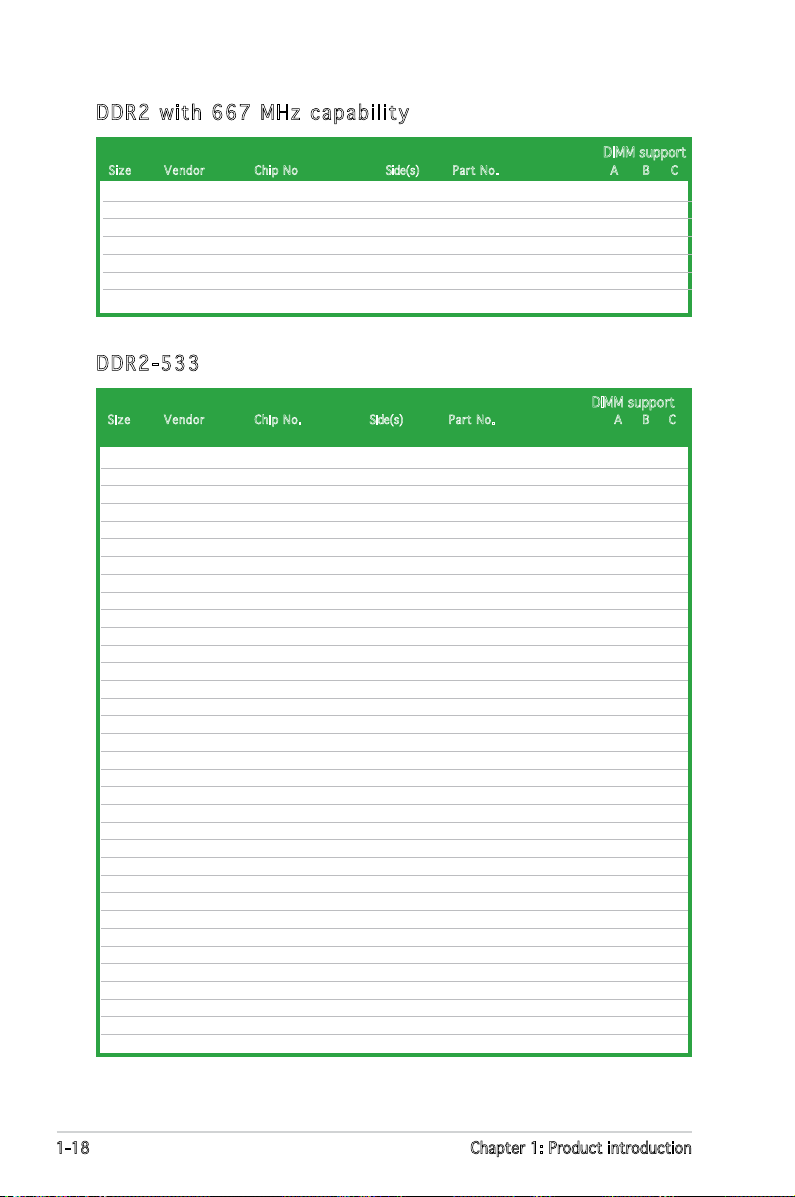
DDR 2 w it h 6 6 7 M Hz ca pab ili ty
(continued on the next page)
Page 30
1-18 Chapter 1: Product introduction
256MB KINGSTON E5116AB-5C-E SS KVR533D2N4/256 • •
512MB KINGSTON HY5PS56821F-C4 DS KVR533D2N4/512 • • •
1024MB KINGSTON D6408TE7BL-37 DS KVR533D2N4/1G • •
2048MB KINGSTON E1108AA-5C-E DS KVR533D2N4/2G •
512MB SAMSUNG K4T51083QB-GCD5 SS M378T6553BG0-CD5 • • •
256MB SAMSUNG K4T56083QF-GCD5 SS M378T3253FG0-CD5 • • •
512MB SAMSUNG K4T56083QF-GCD5 DS M378T6453FG0-CD5 • •
512MB Inneon HYB18T512800AC37 SS HYS64T64000GU-3.7-A • • •
256MB Inneon HYB18T512160AF-3.7 SS HYS64T32000HU-3.7-A • • •
512MB Inneon HYB18T512800AF37 SS HYS64T64000HU-3.7-A • • •
1024MB Inneon HYB18T512800AF37 DS HYS64T128020HU-3.7-A • •
2048MB Inneon HYB18T1G800AF-3.7 DS HYS64T256020HU-3.7-A •
256MB Inneon HYB18T5121608BF-3.7 SS HYS64T32000HU-3.7-B • • •
512MB Inneon HYB18T512800BF37 SS HYS64T64000HU-3.7-B • • •
1024MB Inneon HYB18T512800BF37 DS HYS64T128020HU-3.7-B • •
512MB Hynix HY5PS12821F-C4 SS HYMP564U648-C4 • •
1024MB Hynix HY5PS12821F-C4 DS HYMP512U648-C4 • •
512MB Hynix HY5PS12821AFP-C3 SS HYMP564U64AP8-C3 • • •
1024MB Hynix HY5PS12821AFP-C3 DS HYMP512U64AP8-C3 • •
512MB ELPIDA E5108AB-5C-E SS EBE51UD8ABFA-5C • • •
512MB ELPIDA E5108AB-5C-E SS EBE51UD8ABFA-5C-E • • •
256MB Apacer E5116AB-5C-E SS 78.81077.420 • • •
256MB KINGMAX E5116AB-5C-E SS KLBB68F-36EP4 • •
512MB KINGMAX E5108AE-5C-E SS KLBC28F-A8EB4 • • •
1024MB KINGMAX E5108AE-5C-E DS KLBD48F-A8EB4 • •
512MB Transcend K4T51083QB-GCD5 SS TS64MLQ64V5J • • •
1024MB Transcend K4T51083QB-GCD5 DS TS128MLQ64V5J • •
512MB CENTURY E5108AB-5C-E SS 25V2H8EL5CB4-J43 • • •
256MB elixir N2TU51216AF-37B SS M2U25664TUH4A0F-37B • • •
512MB elixir N2TU51280AF-37B SS M2U51264TU88A0F-37B •
512MB Aeneon AET960UD00-37C88X SS AET660UD00-370A98X • •
512MB Aeneon AET93F370AG0513 SS AET660UD00-370A98X • • •
256MB Aeneon AET94F370A SS AET560UD00-370A98Z • • •
256MB Aeneon AET94F370A SS AET560UD00-370A98X • • •
Siz e Ven dor Chip No. Side(s) Part No . A B C
DIMM support
DDR 2-5 33
1024MB PQI E5108AE-5C-E DS MEAD-403LA • •
512MB WINTEC 4UAI2D9CRZ SS 39127282 • • •
1024MB WINTEC 4WAIID9CWX DS 39137282 • •
512MB MDT 18D51280D-30518 SS M512-667-8 • • •
1024MB MDT 18D51280D-30528 DS M924-667-16 • •
512MB Kingbox DD2640800-667 SS N/A • • •
1024MB Kingbox DD2640800-667 DS N/A • •
Siz e V endor Chip No Side(s) Par t No. A B C
DIMM support
DDR 2 w it h 6 6 7 M Hz ca pab ili ty
(continued on the next page)
Page 31

ASUS P5ND2 1-19
Side(s): SS - Single-sided DS - Double-sided
DIMM support:
A - Supports one module inserted into either slot, in Single-channel memory conguration.
B - Supports one pair of modules inserted into either the yellow slots or the black slots as
one pair of Dual-channel memory conguration.
C - Supports two pairs of modules inserted into the yellow and black slots as two pairs of
Dual-channel memory conguration.
Visit the ASUS website (www.asus.com) for the latest QVL.
512MB Aeneon AET93F370A SS AET660UD00-370A98Z • • •
512MB Aeneon AET93F370A SS AET660UD00-370A98X • • •
512MB Aeneon AET93F370 SS AET660UD00-370A98X • • •
1024MB Aeneon AET93F370A DS AET760UD00-370A98X • •
256MB NANYA NT5TU32M16AF-37B SS NT256T64UH4A0F-37B • • •
512MB NANYA NT5TU64M8AF-37B SS NT512T64U88A0F-37B • • •
1024MB NANYA NT5TU64M8AF-37B DS NT1GT64U8HA0F-37B • •
1024MB PQI 64MX8D2-E DS MEAB-323LA •
512MB PQI 64MX8D2-E SS MEAB-423LA • • •
512MB TwinMOS K4T51083QB-GCD5 SS 8D-22JB5-K2T • • •
256MB SimpleTech 858S032F25A SS SVM-42DR2/256 • •
512MB SimpleTech 858S064F25A DS SVM-42DR2/512 • • •
1024MB Patriot Heat-Sink Package SS PDC21G5600+XBLK •
512MB MDT 18D51280D-3.70S20 SS M512-533-8 • • •
1024MB MDT 18D51280D-3.70448 DS M924-533-16 •
Siz e Ven dor Chip No. Side(s) Part N o. A B C
DIMM support
DDR 2-5 33
Page 32

1-20 Chapter 1: Product introduction
1. 7. 3 In st al li ng a D IM M
Unplug the power supply before adding or removing DIMMs or other
system components. Failure to do so can cause severe damage to both
the motherboard and the components.
To install a DIMM:
1. Unlock a DIMM socket by
pressing the retaining clips
outward.
2. Align a DIMM on the socket
such that the notch on the
DIMM matches the break on
the socket.
3. Firmly insert the DIMM into
the socket until the retaining
clips snap back in place and
the DIMM is properly seated.
1. 7. 4 Re mo vi ng a D IM M
Follow these steps to remove a DIMM.
1. Simultaneously press the retaining
clips outward to unlock the DIMM.
2. Remove the DIMM from the socket.
• A DDR2 DIMM is keyed with a notch so that it ts in only one
direction. Do not force a DIMM into a socket to avoid damaging the
DIMM.
• The DDR2 DIMM sockets do not support DDR DIMMs. DO not install
DDR DIMMs to the DDR2 DIMM sockets.
Unlocked retaining clip
Support the DIMM lightly with
your ngers when pressing
the retaining clips. The DIMM
might get damaged when it
ips out with extra force.
1
2
1
DDR2 DIMM notch
DDR2 DIMM notch
1
2
3
Page 33

ASUS P5ND2 1-21
1.8 Expansion slots
In the future, you may need to install expansion cards. The following
sub-sections describe the slots and the expansion cards that they support.
1. 8. 1 In st al li ng a n ex pa ns io n ca rd
To install an expansion card:
1. Before installing the expansion card, read the documentation that
came with it and make the necessary hardware settings for the card.
2. Remove the system unit cover (if your motherboard is already installed
in a chassis).
3. Remove the bracket opposite the slot that you intend to use. Keep
the screw for later use.
4. Align the card connector with the slot and press rmly until the card is
completely seated on the slot.
5. Secure the card to the chassis with the screw you removed earlier.
6. Replace the system cover.
1. 8. 2 Co nf ig ur in g an e xp an si on c ar d
After installing the expansion card, congure the it by adjusting the
software settings.
1. Turn on the system and change the necessary BIOS settings, if any.
See Chapter 2 for information on BIOS setup.
2. Assign an IRQ to the card. Refer to the tables on the next page.
3. Install the software drivers for the expansion card.
Make sure to unplug the power cord before adding or removing
expansion cards. Failure to do so may cause you physical injury and
damage motherboard components.
When using PCI cards on shared slots, ensure that the drivers support
“Share IRQ” or that the cards do not need IRQ assignments. Otherwise,
conicts will arise between the two PCI groups, making the system
unstable and the card inoperable. Refer to the table on the next page for
details.
Page 34

1-22 Chapter 1: Product introduction
1. 8. 3 In te rr up t as si gn me nt s
* These IRQs are usually available for PCI devices.
IRQ as si g nm e nt s f or th i s m ot h er boa rd
A B C D E F G H
PCI Express x16 slot 1 — — — — shared — — —
PCI Express x1 slot 1 — — — — shared — — —
PCI Express x1 slot 2 — — — — — used — —
PCI Express x1 slot 3 — — — — — — — used
PCI slot 1 shared — — — — — — —
PCI slot 2 — shared — — — — — —
Onboard USB1.0 controller 1 shared — — — — — — —
Onboard USB1.0 controller 2 — shared — — — — — —
Onboard USB2.0 controller — — shared — — — — —
Onboard LAN — — shared — — — — —
Onboard IDE controller — — — — shared — — —
Onboard SATA controller shared — — — — — — —
Onboard Audio controller shared — — — — — — —
Sta nda rd in t er r up t a ss i gn m en t s
IRQ Priority Standard Function
0 1 System Timer
1 2 Keyboard Controller
2 — Re-direct to IRQ#9
4 12 Communications Port (COM1)*
5 13 IRQ holder for PCI steering*
6 14 Floppy Disk Controller
7 15 Printer Port (LPT1)*
8 3 System CMOS/Real Time Clock
9 4 IRQ holder for PCI steering*
10 5 IRQ holder for PCI steering*
11 6 IRQ holder for PCI steering*
12 7 PS/2 Compatible Mouse Port*
13 8 Numeric Data Processor
14 9 Primary IDE Channel
15 10 Secondary IDE Channel
Page 35

ASUS P5ND2 1-23
1. 8. 4 PC I sl ot s
The PCI slots support cards such
as a LAN card, SCSI card, USB card,
and other cards that comply with
PCI specications. The gure shows
a LAN card installed on a PCI slot.
1. 8. 5 PCI E xp res s x1 sl ot
This motherboard supports PCI
Express x1 network cards, SCSI cards
and other cards that comply with the
PCI Express specications. The gure
shows a network card installed on the
PCI Express x1 slot.
1. 8. 6 PC I Ex pr es s x1 6 sl ot
This motherboard supports PCI
Express x16 graphic cards that comply
with the PCI Express specications.
The gure shows a graphics card
installed on the PCI Express x16 slot.
Page 36

1-24 Chapter 1: Product introduction
1.9 Jumpers
1. Cle a r RT C RAM ( CLR T C )
This jumper allows you to clear the Real Time Clock (RTC) RAM in
CMOS. You can clear the CMOS memory of date, time, and system
setup parameters by erasing the CMOS RTC RAM data. The onboard
button cell battery powers the RAM data in CMOS, which include
system setup information such as system passwords.
To erase the RTC RAM:
1. Turn OFF the computer and unplug the power cord.
2. Remove the onboard battery.
3. Move the jumper cap from pins 1-2 (default) to pins 2-3. Keep the
cap on pins 2-3 for about 5~10 seconds, then move the cap back
to pins 1-2.
4. Re-install the battery.
5. Plug the power cord and turn ON the computer.
6. Hold down the <Del> key during the boot process and enter BIOS
setup to re-enter data.
Except when clearing the RTC RAM, never remove the cap on CLRTC
jumper default position. Removing the cap will cause system boot failure!
P5ND2
R
CLRTC
Normal Clear CMO
S
(Default)
2 31 2
P5ND2 Clear RTC RAM
Page 37

ASUS P5ND2 1-25
2. USB d evi c e wa k e -up ( 3-p i n US B P W12 3 4 , U S B PW3 4 ,
USB P W 78)
Set these jumpers to +5V to wake up the computer from S1 sleep
mode (CPU stopped, DRAM refreshed, system running in low power
mode) using the connected USB devices. Set to +5VSB to wake up
from S3 and S4 sleep modes (no power to CPU, DRAM in slow refresh,
power supply in reduced power mode).
• The USB device wake-up feature requires a power supply that can
provide 500mA on the +5VSB lead for each USB port; otherwise,
the system would not power up.
• The total current consumed must NOT exceed the power supply
capability (+5VSB) whether under normal condition or in sleep mode.
P5ND2
R
P5ND2 USB device Wake up
3
2
2
1
USBPW1234
USBPW78
+5V
(Default)
+5VSB
USBPW56
3
2
2
1
+5V
(Default)
+5VSB
3
2
2
1
+5V
(Default)
+5VS
B
Page 38

1-26 Chapter 1: Product introduction
1.10 Connectors
1. 10. 1 Re ar p an el c on ne ct or s
1. PS/ 2 mou s e po r t (g r e en) . This port is for a PS/2 mouse.
2. Par a l lel p ort . This 25-pin port connects a parallel printer, a scanner,
or other devices.
3. LA N ( R J -45 ) por t . Supported by Marvell® Gigabit LAN
controller, this port allows Gigabit connection to a Local
Area Network (LAN) through a network hub.
Refer to the audio conguration table below for the function of the audio
ports in 2, 4, or 6-channel conguration.
Aud io 2, 4, or 6- c ha nne l c on f ig u ra t io n
Light Blue Line In Rear Speaker Out Surround
Lime Line Out Front Speaker Out Front Speaker Out
Pink Mic In Mic In Center/Bass
Port Headset 4-channel 6-channel
2-channel
SPEED
LED
ACTIVITY/
LINK LED
LAN port
* Blinking
4. Lin e In p o rt ( l igh t blu e ) . This port connects the tape, CD, DVD
player, or other audio sources.
5. Lin e Out p ort ( lim e ) . This port connects a headphone or a
speaker. In 4-channel, and 6-channel conguration, the function of this
port becomes Front Speaker Out.
6. Mic r o pho n e po r t (p i n k). This port connects a microphone.
OFF OFF Soft-off Mode
Orange* OFF During Power ON/OFF or 10Mbps connection
Orange* Orange 100Mbps connection
Orange* Green 1Gbps connection
Activity/Link LED Speed LED Description
1
11
4
5
6
7
2 3
10 89
Page 39

ASUS P5ND2 1-27
7. USB 2 .0 p o rts 3 an d 4. These two 4-pin Universal Serial Bus
(USB) ports are available for connecting USB 2.0 devices.
8. USB 2 . 0 p o r ts 1 and 2 . These two 4-pin Universal Serial Bus (USB)
ports are available for connecting USB 2.0 devices.
9. Ser i a l p o r t. This port connects a mouse, modem, or other devices
that conform with serial specication.
10. C oax i a l S / P DIF O ut p ort . This port connects an external audio
output device via a coaxial S/PDIF cable.
11. P S/2 k eyb o a rd p ort ( pur p l e). This port is for a PS/2 keyboard.
1. 10. 2 In te rn al c on ne ct or s
1. Flo p p y d i s k d r i ve c o nne c t or ( 34- 1 pin F LOP P Y )
This connector is for the provided oppy disk drive (FDD) signal cable.
Insert one end of the cable to this connector, then connect the other
end to the signal connector at the back of the oppy disk drive.
Pin 5 on the connector is removed to prevent incorrect cable connection
when using a FDD cable with a covered Pin 5.
P5ND2
R
NOTE: Orient the red markings o
n
the floppy ribbon cable to PIN 1.
PIN 1
FLOPPY
P5ND2 Floppy Disk Drive Connector
Page 40

1-28 Chapter 1: Product introduction
2. IDE c onn e c tor s (40 - 1 pi n PRI _ I DE, S EC _ I DE)
The onboard IDE connectors are for Ultra DMA 133/100/66 signal
cables. There are three connectors on each Ultra DMA 133/100/66
signal cable: blue, black, and gray. Connect the blue connector to
the motherboard’s IDE connector, then select one of the following
modes to congure your device(s).
Black or gray
Drive jumper Mode Cable
setting of device(s) connector
Single device Cable-Select or Master - Black
Two devices Cable-Select Master Black
Slave Gray
Master Master
Slave Slave
• Pin 20 on the IDE connector is removed to match the covered hole
on the Ultra DMA cable connector. This prevents incorrect insertion
when you connect the IDE cable.
• Use the 80-conductor IDE cable for Ultra DMA 133/100/66 IDE devices.
If any device jumper is set as “Cable-Select,” make sure all other device
jumpers have the same setting.
P5ND2
R
P5ND2 IDE Connectors
NOTE: Orient the red markings
(usually zigzag) on the ID
ribbon cable to PIN 1.
SEC_IDE
PRI_IDE
Page 41

ASUS P5ND2 1-29
3. Ser i a l A T A co n n ect o r s ( 7 - pin S ATA 1 , S A T A2, S ATA 3 ,
SAT A 4 )
These connectors are for the Serial ATA signal cables for Serial ATA
hard disk devices. The current Serial ATA I interface allows up to 150
MB/s data transfer rate while Serial ATA II allows up to 300 MB/s data
transfer rate, faster than the standard parallel ATA with 133 MB/s
(DMA/133).
4. Aud i o co n n ect o r s ( 4 - pin C D, A U X)
These connectors allow you to receive stereo audio input from sound
sources such as a CD-ROM, TV-tuner, or MPEG card.
P5ND2
R
P5ND2 SATA Connectors
SATA3
GND
RSATA_TXP3
RSATA_TXN3
GND
RSATA_RXP3
RSATA_RXN3
GND
SATA4
GND
GND
GND
RSATA_RXN4
RSATA_TXN4
RSATA_TXN4
RSATA_RXP4
SATA2
GND
GND
GND
RSATA_RXN2
RSATA_TXN2
RSATA_TXN2
RSATA_RXP2
SATA1
GND
RSATA_TXP1
RSATA_TXN1
GND
RSATA_RXP1
SATA_RXN1
GND
P5ND2
R
P5ND2 Internal Audio Connectors
AUX
(White)
Right Audio Channel
Left Audio Channel
Ground
Ground
CD
(black)
Right Audio Channel
Left Audio Channel
Ground
Ground
Page 42

1-30 Chapter 1: Product introduction
5. USB c onn e c tor s (10 - 1 pi n USB 5 6 , U S B 78)
These connectors are for USB 2.0 ports. Connect the USB module
cable to any of these connectors, then install the module to a slot
opening at the back of the system chassis. These USB connectors
comply with USB 2.0 specication that supports up to 480 Mbps
connection speed.
6. GAM E / MID I por t con n e cto r (16 - 1 pi n GA M E )
This connector is for a GAME/MIDI port. Connect the USB/GAME
module cable to this connector, then install the module to a slot
opening at the back of the system chassis. The GAME/MIDI port
connects a joystick or game pad for playing games, and MIDI devices
for playing or editing audio les.
Never connect a 1394 cable to the USB connectors. Doing so will
damage the motherboard!
The GAME module is purchased separately.
The USB module is purchased separately.
P5ND2
R
USB78
USB+5V
USB_P8-
USB_P8+
GND
NC
USB+5V
USB_P7-
USB_P7+
GND
1
USB56
USB+5V
USB_P6
USB_P6
GND
NC
USB+5V
USB_P5-
USB_P5+
GND
1
P5ND2
USB2.0 Connectors
P5ND2
R
P5ND2 Game Connector
GAME
+5V +5V
J2B1
J2CX
MIDI_OUT
J2CY
J2B2
MIDI_IN
J1B1
X
GND
GND
Y
J1B2
+5V
Page 43

ASUS P5ND2 1-31
8. CPU , Pow e r an d Cha s s is F a n c o n nec t ors
(4- p i n C P U _FA N , 3- p i n P W R _FA N , 3- p i n C H A _FA N )
The fan connectors support cooling fans of 350 mA ~ 2000 mA (24
W max.) or a total of 1 A ~ 3.48 A (41.76 W max.) at +12V. Connect
the fan cables to the fan connectors on the motherboard, making
sure that the black wire of each cable matches the ground pin of the
connector.
Do not forget to connect the fan cables to the fan connectors.
Insufcient air ow inside the system may damage the motherboard
components. These are not jumpers! Do not place jumper caps on the
fan connectors!
7. Aza l i a A n a log F ron t Pan e l (1 0 - 1 p i n A A F P)
This connector is for a chassis-mounted front panel audio I/O module
that supports legacy AC ‘97 audio standard. Connect one end of the
front panel audio I/O module cable to this connector.
P5ND2
R
P5ND2 Azalia Analog Front Panel Connector
HP_HD
MIC2_L
HP_R
HP_L
MIC2_JD
Jack_Sense
MIC2_R
PRESENSE#
AGND
AAFP
P5ND2
R
P5ND2
Fan Connectors
CPU_FAN
GND
CPU FAN PWR
CPU FAN IN
CPU FAN PWM
PWR_FAN
GND
Rotation
+12V
CHA_FAN
GND
Rotation
+12V
Page 44

1-32 Chapter 1: Product introduction
9. Cha s s is i n tru s i on c o nne c t or ( 4 -1 p in C H ASS I S )
This connector is for a chassis-mounted intrusion detection sensor
or switch. Connect one end of the chassis intrusion sensor or switch
cable to this connector. The chassis intrusion sensor or switch sends
a high-level signal to this connector when a chassis component
is removed or replaced. The signal is then generated as a chassis
intrusion event.
By default, the pins labeled “Chassis Signal” and “Ground” are shorted
with a jumper cap. Remove the jumper caps only when you intend to
use the chassis intrusion detection feature.
P5ND2
R
P5ND2 Chassis Intrusion Connector
CHASSIS
+5VSB_MB
Chassis Signal
GND
(Default
)
10. D igi t a l a u d io c o nn e c tor ( 4-1 p in S P DIF _ O UT)
This connector is for an additional Sony/Philips Digital Interface
(S/PDIF) port(s). Connect the S/PDIF module cable to this connector,
then install the module to a slot opening at the back of the system
chassis.
The S/PDIF module is purchased separately.
P5ND2
R
P5ND2 Digital Audio Connector
+5V
SPDIFOUT
GND
SPDIF_OUT
Page 45

ASUS P5ND2 1-33
•
For a fully congured system, we recommend that you use a power
supply unit (PSU) that complies with ATX 12 V Specication 2.0 (or
later version) and provides a minimum power of 400 W.
• Do not forget to connect the 4-pin ATX +12 V power plug;
otherwise, the system will not boot.
• Use of a PSU with a higher power output is recommended when
conguring a system with more power-consuming devices. The
system may become unstable or may not boot up if the power is
inadequate.
11. A T X p ower connector s
(24 - p in E A TXP W R , 4 - p in A T X12 V )
These connectors are for ATX power supply plugs. The power supply
plugs are designed to t these connectors in only one orientation.
Find the proper orientation and push down rmly until the connectors
completely t.
P5ND2
R
P5ND2 ATX Power Connector
+3 Volts
+3 Volts
Ground
+5 Volts
+5 Volts
Ground
Ground
Power O
+5V Standby
+12 Volts
-5 Volts
+5 Volts
+3 Volts
-12 Volts
Ground
Ground
Ground
PSON#
Ground
+5 Volts
+12 Volts
+3 Volts
+5 Volts
Ground
+12V DC
GND
+12V DC
GND
ATX12V
EATXPWR
Page 46

1-34 Chapter 1: Product introduction
12. S yst e m pa n e l c o nne c t or ( 2 0-p i n PA N E L)
This connector supports several chassis-mounted functions.
The sytem panel connector is color-coded for easy connection. Refer to
the connector description below for details.
•
Sys t e m p o w er L E D ( G r een 2 -pi n PLE D )
This 3-pin connector is for the system power LED. Connect the chassis
power LED cable to this connector. The system power LED lights up
when you turn on the system power, and blinks when the system is in
sleep mode.
•
Har d dis k dri v e ac t i vit y LED ( Re d 2-p i n ID E _ LED )
This 2-pin connector is for the HDD Activity LED. Connect the HDD
Activity LED cable to this connector. The IDE LED lights up or ashes
when data is read from or written to the HDD.
•
Sys t e m w a r nin g spe a k er ( O ran g e 2- p in S P EAK E R )
This 4-pin connector is for the chassis-mounted system warning
speaker. The speaker allows you to hear system beeps and warnings.
•
AT X powe r but ton/so ft-of f butt on (Li ght Green 2 -pin P WRSW)
This connector is for the system power button. Pressing the power
button turns the system on or puts the system in sleep or soft-off
mode depending on the BIOS settings. Pressing the power switch for
more than four seconds while the system is ON turns the system OFF.
•
Res e t bu t t on ( B lue 2 -pi n RES E T )
This 2-pin connector is for the chassis-mounted reset button for
system reboot without turning off the system power.
P5ND2
R
P5ND2 System Panel Connector
* Requires an ATX power suppl
y
PANEL
PLED-
PWR
+5V
Speaker
Ground
RESET
Ground
Reset
Ground
Ground
PWRSW
PLED+
IDE_LED-
IDE_LED+
IDE_LED
PLED SPEAKER
Page 47

ASUS P5ND2 2-1
2
BIOS setup
This chapter tells how to change
the system settings through the BIOS
Setup menus. Detailed descriptions
of the BIOS parameters are also
provided.
Page 48

2-2 Chapter 2: BIOS setup
2.1 Managing and updating your BIOS
The following utilities allow you to manage and update the motherboard
Basic Input/Output System (BIOS) setup.
1.
Awa r d BI O S Fl a s h U t i lit y (Updates the BIOS in DOS mode using a
bootable oppy disk.)
2.
ASU S Cra s h Fre e BIO S 2 (Updates the BIOS using a bootable oppy
disk or the motherboard support CD when the BIOS le fails or gets
corrupted.)
3.
ASU S EZ F l ash (Updates the BIOS in DOS using a oppy disk or the
motherboard support CD.)
4.
ASU S Upd a t e (Updates the BIOS in Windows® environment.)
Refer to the corresponding sections for details on these utilities.
2. 1. 1 Cr ea ti ng a b oo ta bl e fl op py d is k
1. Do either one of the following to create a bootable oppy disk.
DOS environment
a. Insert a 1.44MB oppy disk into the drive.
b. At the DOS prompt, type
format
A:/S
then press <Enter>.
Windows® XP environment
a. Insert a 1.44 MB oppy disk to the oppy disk drive.
b. Click
Start from the Windows® desktop, then select My Computer.
c. Select the 3 1/2 Floppy Drive icon.
d. Click
Fil e from the menu, then select F orm a t . A For m at 3 1/2
Flo p p y D i s k window appears.
e. Select
Cre a t e a n MS- D O S s t a rtu p dis k from the format
options eld, then click Start.
Windows® 2000 environment
To create a set of boot disks for Windows® 2000:
a. Insert a formatted, high density 1.44 MB oppy disk into the drive.
b. Insert the Windows
®
2000 CD to the optical drive.
Save a copy of the original motherboard BIOS le to a bootable oppy
disk in case you need to restore the BIOS in the future. Copy the original
motherboard BIOS using the ASUS Update or AwardBIOS Flash utilities.
Page 49

ASUS P5ND2 2-3
c. Click Star t , then select R un.
d. From the Open eld, type
D:\bootdisk\makeboot a:
assuming that D: is your optical drive.
e. Press <Enter>, then follow screen instructions to continue.
2. Copy the original or the latest motherboard BIOS le to the bootable
oppy disk.
2. 1. 2 Up da ti ng t he B IO S
The Basic Input/Output System (BIOS) can be updated using the AwardBIOS
Flash Utility. Follow these instructions to update the BIOS using this utility.
1. Download the latest BIOS le from the ASUS web site. Rename the le
to P5N D 2 .BI N and save it to a oppy disk.
Save only the updated BIOS le in the oppy disk to avoid loading the
wrong BIOS le.
2. Copy the AwardBIOS Flash Utility (awdash.exe) from the Software
folder of the support CD to the oppy disk with the latest BIOS le.
3. Boot the system in DOS mode using the bootable oppy disk you
created earlier.
4. When the
A:> appears, replace the bootable oppy disk with the
oppy disk containing the new BIOS le and the Award BIOS Flash
Utility.
5. At the prompt, type
awd f l ash then press
<Enter>. The Award
BIOS Flash Utility screen
appears.
AwardBIOS Flash Utility for ASUS V1.08
(C) Phoenix Technologies Ltd. All Rights Reserved
Message: Please input File Name!
For nForce_ultra-P5ND2-00 DATE: 04/10/2006
Flash Type - SST 49LF004A/B /3.3V
File Name to Program:
Page 50

2-4 Chapter 2: BIOS setup
6. Type the BIOS le name
in the Fil e Nam e to
Pro g r am eld, then
press <Enter>.
7. Press <N> when the utility prompts you to save the current BIOS le.
The following screen appears.
8. The utility veries the
BIOS le in the oppy
disk and starts ashing
the BIOS le.
Do not turn off or reset the system during the ashing process!
AwardBIOS Flash Utility for ASUS V1.08
(C) Phoenix Technologies Ltd. All Rights Reserved
Warning: Don’t Turn Off Power Or Reset System!
For nForce_ultra-P5ND2-00 DATE: 04/10/2006
Flash Type - SST 49LF004A/B /3.3V
File Name to Program: P5NSLI.bin
Program Flashing Memory - OFE00 OK
Write OK No Update Write Fail
AwardBIOS Flash Utility for ASUS V1.08
(C) Phoenix Technologies Ltd. All Rights Reserved
For nForce_ultra-P5ND2-00 DATE: 04/10/2006
Flash Type - SST 49LF004A/B /3.3V
File Name to Program: P5NSLI.bin
Message: Do You Want To Save Bios (Y/N)
9. The utility displays a
Fla s h ing C omp l e te
message indicating that
you have successfully
ashed the BIOS le.
Remove the oppy disk
then press <F1> to
restart the system.
AwardBIOS Flash Utility for ASUS V1.08
(C) Phoenix Technologies Ltd. All Rights Reserved
F1
Reset
For nForce_ultra-P5ND2-00 DATE: 04/10/2006
Flash Type - SST 49LF004A/B /3.3V
File Name to Program: P5NSLI.bin
Flashing Complete
Press <F1> to Continue
Write OK No Update Write Fail
Page 51

ASUS P5ND2 2-5
To save the current BIOS le using the AwardBIOS Flash Utility:
1. Follow steps 1 to 6 of
the previous section.
2. Press <Y> when the
utility prompts you
to save the current
BIOS le. The following
screen appears.
3. Type a lename for the
current BIOS le in the
Sav e cur r e nt B I OS
as eld, then press
<Enter>.
4. The utility saves the
current BIOS le to the
oppy disk, then returns
to the BIOS ashing
process.
2. 1. 3 Sa vi ng t he c ur re nt B IO S fi le
You can use the AwardBIOS Flash Utility to save the current BIOS le. You
can load the current BIOS le when the BIOS le gets corrupted during the
ashing process.
AwardBIOS Flash Utility for ASUS V1.08
(C) Phoenix Technologies Ltd. All Rights Reserved
Message:
For nForce_ultra-P5ND2-00 DATE: 04/10/2006
Flash Type - SST 49LF004A/B /3.3V
File Name to Program: 1001.bin
Save current BIOS as:
AwardBIOS Flash Utility for ASUS V1.08
(C) Phoenix Technologies Ltd. All Rights Reserved
Message: Please Wait!
For nForce_ultra-P5ND2-00 DATE: 04/10/2006
Flash Type - SST 49LF004A/B /3.3V
File Name to Program: 1001.bin
Checksum: DAD6H
Save current BIOS as: old.bin
AwardBIOS Flash Utility for ASUS V1.08
(C) Phoenix Technologies Ltd. All Rights Reserved
Message: Please Wait!
For nForce_ultra-P5ND2-00 DATE: 04/10/2006
Flash Type - SST 49LF004A/B /3.3V
File Name to Program: 1001.bin
Now Backup System BIOS to
File!
Make sure that the oppy disk has enough disk space to save the le.
Page 52

2-6 Chapter 2: BIOS setup
2. 1. 4 AS US C ra sh Fr ee B IO S 2 u t i l i t y
The ASUS CrashFree BIOS 2 is an auto recovery tool that allows you to
restore the BIOS le when it fails or gets corrupted during the updating
process. You can update a corrupted BIOS le using the motherboard
support CD or the oppy disk that contains the updated BIOS le.
Prepare the motherboard support CD or the oppy disk containing the
updated motherboard BIOS before using this utility.
Rec ove ri n g t he BI OS fr o m t he su p po rt CD
To recover the BIOS from the support CD:
1. Turn on the system.
2. Insert the motherboard support CD to the optical drive.
3. The utility displays the following message and automatically checks
the CD for the BIOS le.
4. Restart the system after the utility completes the updating process.
DO NOT shut down or reset the system while updating the BIOS! Doing
so can cause system boot failure!
Award BootBlock BIOS v1.0
Copyright (c) 2000, Award Software, Inc.
BIOS ROM checksum error
Detecting IDE ATAPI device...
Found CDROM, try to Boot from it... Pass
When found, the utility reads the BIOS le and starts ashing the
corrupted BIOS le.
Award BootBlock BIOS v1.0
Copyright (c) 2000, Award Software, Inc.
BIOS ROM checksum error
Detecting IDE ATAPI device...
Page 53

ASUS P5ND2 2-7
The recovered BIOS may not be the latest BIOS version for this
motherboard. Visit the ASUS website (www.asus.com) to download the
latest BIOS le.
Rec ove ri n g t he BI OS fr o m a f l op p y dis k
To recover the BIOS from the oppy disk:
1. Remove any CD from the optical drive, then turn on the system.
2. Insert the oppy disk with the original or updated BIOS le to the
oppy disk drive.
3. The utility displays the following message and automatically checks
the optical drive for the original or updated BIOS le.
4. Restart the system after the utility completes the updating process.
DO NOT shut down or reset the system while updating the BIOS! Doing
so can cause system boot failure!
When no CD is found, the utility automatically checks the oppy disk
for the original or updated BIOS le. The utility then updates the
corrupted BIOS le.
Award BootBlock BIOS v1.0
Copyright (c) 2000, Award Software, Inc.
BIOS ROM checksum error
Detecting IDE ATAPI device...
Found CDROM, try to Boot from it... Fail
Detecting oppy drive A media...
Award BootBlock BIOS v1.0
Copyright (c) 2000, Award Software, Inc.
BIOS ROM checksum error
Detecting IDE ATAPI device...
Page 54

2-8 Chapter 2: BIOS setup
2. 1. 5 AS US E Z Fl as h ut il it y
The ASUS EZ Flash feature allows you to update the BIOS without having
to go through the long process of booting from a oppy disk and using
a DOS-based utility. The EZ Flash utility is built-in the BIOS chip so it is
accessible by pressing <Alt> + <F2> during the Power-On Self-Test (POST).
To update the BIOS using EZ Flash:
1. Visit the ASUS website (www.asus.com) to download the latest BIOS
le for the motherboard.
2. Save the BIOS le to a oppy disk, then restart the system.
3. Press <Alt> + <F2> during POST to display the following.
Insert Disk then press Enter or ESC to continue POST
4. Insert the oppy disk
that contains the
BIOS le to the oppy
disk drive then press
<Enter>. The following
screen appears.
Do not shutdown or reset the system while updating the BIOS to prevent
system boot failure!
AwardBIOS Flash Utility for ASUS V1.08
(C) Phoenix Technologies Ltd. All Rights Reserved
Message: Please wait...
For nForce_ultra-P5ND2-00 DATE: 04/10/2006
Flash Type - SST 49LF004A/B /3.3V
File Name to Program:
5. When the correct BIOS le is found, EZ Flash performs the BIOS update
process and automatically reboots the system when done.
Page 55

ASUS P5ND2 2-9
Ins tal li n g A SU S U p da te
To install ASUS Update:
1. Place the support CD in the optical drive. The Drivers menu appears.
2. Click the Utilities tab, then click Install ASUS Update VX.XX.XX. See
page 3-4 for the Utilities screen menu.
3. The ASUS Update utility is copied to your system.
2. 1. 6 AS US U p d a t e u t i l i t y
The ASUS Update is a utility that allows you to manage, save, and update
the motherboard BIOS in Windows® environment. The ASUS Update utility
allows you to:
• Save the current BIOS le
• Download the latest BIOS le from the Internet
• Update the BIOS from an updated BIOS le
• Update the BIOS directly from the Internet, and
• View the BIOS version information.
This utility is available in the support CD that comes with the motherboard
package.
ASUS Update requires an Internet connection either through a network
or an Internet Service Provider (ISP).
Quit all Windows® applications before you update the BIOS using this
utility.
Page 56

2-10 Chapter 2: BIOS setup
3. Select the ASUS FTP site
nearest you to avoid network
trafc, or click Aut o Sel e c t.
Click Nex t .
Upd ati ng th e B I OS th rou gh th e I n te rne t
To update the BIOS through the Internet:
1. Launch the ASUS Update utility from the Windows
®
desktop by clicking
Sta r t > P r ogr a m s > A SUS > AS U S Upd a t e > A SUS U p dat e . The
ASUS Update main window appears.
2. Select U pda t e BI O S fr o m
the I nte r n et option from the
drop-down menu, then click
Next.
Page 57

ASUS P5ND2 2-11
Upd ati ng th e B I OS th rou gh a B IO S f ile
To update the BIOS through a BIOS le:
1. Launch the ASUS Update utility from the Windows
®
desktop by clicking
Sta r t > P r ogr a m s > A SUS > ASU S U pda t e > A S USU p d ate . The
ASUS Update main window appears.
2. Select
Upd a t e B I O S f r o m a
fil e option from the drop-down
menu, then click Nex t .
4. From the FTP site, select the
BIOS version that you wish to
download. Click Next.
5. Follow the screen instructions to
complete the update process.
3. Locate the BIOS le from the O pen window, then click O pen .
4. Follow the screen instructions to
complete the update process.
The ASUS Update utility is
capable of updating itself
through the Internet. Always
update the utility to avail all
its features.
Page 58

2-12 Chapter 2: BIOS setup
2.2 BIOS setup program
This motherboard supports a programmable Low-Pin Count (LPC) chip
that you can update using the provided utility described in section “4.1
Managing and updating your BIOS.”
Use the BIOS Setup program when you are installing a motherboard,
reconguring your system, or prompted to “Run Setup”. This section
explains how to congure your system using this utility.
Even if you are not prompted to use the Setup program, you can change
the conguration of your computer in the future. For example, you can
enable the security password feature or change the power management
settings. This requires you to recongure your system using the BIOS Setup
program so that the computer can recognize these changes and record
them in the CMOS RAM of the LPC chip.
The LPC chip on the motherboard stores the Setup utility. When you start
up the computer, the system provides you with the opportunity to run this
program. Press <Del> during the Power-On Self-Test (POST) to enter the
Setup utility; otherwise, POST continues with its test routines.
If you wish to enter Setup after POST, restart the system by pressing
<Ctrl>+<Alt>+<Del>, or by pressing the reset button on the system
chassis. You can also restart by turning the system off and then back on.
Do this last option only if the rst two failed.
The Setup program is designed to make it as easy to use as possible. Being
a menu-driven program, it lets you scroll through the various sub-menus
and make your selections from the available options using the navigation
keys.
• The default BIOS settings for this motherboard apply for most
conditions to ensure optimum performance. If the system becomes
unstable after changing any BIOS settings, load the default settings
to ensure system compatibility and stability. Select the Load Default
Settings item under the Exit Menu. See section “2.7 Exit Menu.”
• The BIOS setup screens shown in this section are for reference
purposes only, and may not exactly match what you see on your
screen.
• Visit the ASUS website (www.asus.com) to download the latest BIOS
le for this motherboard.
Page 59

ASUS P5ND2 2-13
2. 2. 2 Me nu b ar
The menu bar on top of the screen has the following main items:
Mai n For changing the basic system conguration
Adv a n ced For changing the advanced system settings
Pow e r For changing the advanced power management (APM)
conguration
Boo t For changing the system boot conguration
Exi t For selecting the exit options and loading default settings
To select an item on the menu bar, press the right or left arrow key on the
keyboard until the desired item is highlighted.
2. 2. 1 BI OS m en u sc re en
• The BIOS setup screens shown in this chapter are for reference
purposes only, and may not exactly match what you see on your
screen.
• Visit the ASUS website (www.asus.com) to download the latest BIOS
information.
F1:Help
↑↓
: Select Item -/+: Change Value F5: Setup Defaults
ESC: Exit
→←
: Select Menu Enter: Select Sub-menu F10: Save and Exit
Phoenix-Award BIOS CMOS Setup Utility
Main Advanced Power Boot Exit
Select Menu
Item Specic Help
Change the day, month,
year and century.
System Time 15 : 30 : 36
System Date Mon, Feb 6 2006
Legacy Diskette A: [1.44M, 3.5 in.]
Primary IDE Master [ST321122A]
Primary IDE Slave [ASUS CDS520/A]
Secondary IDE Master [None]
Secondary IDE Slave [None]
First SATA Master [None]
Second SATA Master [None]
Third SATA Master [None]
Fourth SATA Master [None]
HDD SMART Monitoring [Disabled]
Installed Memory 256MB
Usable Memory 256MB
Legend bar
General helpMenu bar
Sub-menu items
Conguration eldsMenu items
Page 60

2-14 Chapter 2: BIOS setup
2. 2. 4 Me nu i te ms
The highlighted item on the menu bar displays the specic items for that
menu. For example, selecting Main shows the Mai n menu items.
The other items (Advanced, Power, Boot, and Exit) on the menu bar have
their respective menu items.
2. 2. 5 Su b- me nu i te ms
A solid triangle before each item on any menu screen means that the
iteam has a sub-menu. To display the sub-menu, select the item and press
<Enter>.
2. 2. 6 Co nf ig ur at io n fi el ds
These elds show the values for the menu items. If an item is
user-congurable, you can change the value of the eld opposite the item.
You cannot select an item that is not user-congurable.
A congurable eld is enclosed in brackets, and is highlighted when
selected. To change the value of a eld, select it then press <Enter> to
display a list of options. Refer to “2.2.7 Pop-up window.”
2. 2. 3 Le ge nd b ar
At the bottom of the Setup screen is a legend bar. The keys in the legend
bar allow you to navigate through the various setup menus. The following
table lists the keys found in the legend bar with their corresponding
functions.
Navigation Key Function
<F1> Displays the General Help screen
<F5> Loads setup default values
<Esc> Exits the BIOS setup or returns to the main menu from a
sub-menu
Left or Right arrow Selects the menu item to the left or right
Up or Down arr ow Moves the highlight up or down between elds
Page Down or – (minus) Scrolls backward through the values for the highlighted
eld
Page Up or + (pl us) Scrolls forward through the values for the highlighted eld
<Enter> Brings up a selection menu for the highlighted eld
<F10> Saves changes and exit
Page 61

ASUS P5ND2 2-15
2. 2. 7 Po p- up w in do w
Select a menu item then press <Enter> to display a pop-up window with
the conguration options for that item.
2. 2. 8 Ge ne ra l he lp
At the top right corner of the menu screen is a brief description of the
selected item.
Pop-up menu
F1:Help
↑↓
: Select Item -/+: Change Value F5: Setup Defaults
ESC: Exit
→←
: Select Menu Enter: Select Sub-menu F10: Save and Exit
Phoenix-Award BIOS CMOS Setup Utility
Main Advanced Power Boot Exit
Select Menu
Item Specic Help
Species the capacity and
physical size of diskette
drive A.
System Time 15 : 30 : 36
System Date Mon, Feb 6 2006
Legacy Diskette A: [1.4M, 3.5 in.]
Primary IDE Maste`r [ST32112A]
Primary IDE Slave [ASUS CDS520/A]
Secondary IDE Master [None]
Secondary IDE Slave [None]
First SATA Master [None]
Second SATA Slave [None]
Third SATA Master [None]
Fourth SATA Slave [None]
HDD SMART Monitoring [Disabled]
Installed Memory 256MB
Legacy Diskette A:
Disabled ..... [ ]
720K , 3.5 in. ..... [ ]
1.44M, 3.5 in. ..... [ ]
↑↓
:Move ENTER:Accept ESC:Abort
Page 62

2-16 Chapter 2: BIOS setup
F1:Help
↑↓
: Select Item -/+: Change Value F5: Setup Defaults
ESC: Exit
→←
: Select Menu Enter: Select Sub-menu F10: Save and Exit
Phoenix-Award BIOS CMOS Setup Utility
Main Advanced Power Boot Exit
Select Menu
Item Specic Help
Change the day, month,
year and century.
System Time 15 : 30 : 36
System Date Mon, Feb 6 2006
Legacy Diskette A: [1.44M, 3.5 in.]
Primary IDE Master [ST321122A]
Primary IDE Slave [ASUS CDS520/A]
Secondary IDE Master [None]
Secondary IDE Slave [None]
First SATA Master [None]
Second SATA Master [None]
Third SATA Master [None]
Fourth SATA Master [None]
HDD SMART Monitoring [Disabled]
Installed Memory 256MB
Usable Memory 256MB
2.3 Main menu
When you enter the BIOS Setup program, the Main menu screen appears,
giving you an overview of the basic system information.
2. 3. 1 Sy st em T im e [x x: xx :x xx x]
Allows you to set the system time.
2. 3. 2 Sy st em D at e [D ay x x/ xx /x xx x]
Allows you to set the system date.
2. 3. 3 Le ga cy D is ke tt e A [1 .4 4 M, 3 .5 i n. ]
Sets the type of oppy drive installed. Conguration options: [Disabled]
[720K , 3.5 in.] [1.44M, 3.5 in.]
Refer to section “2.2.1 BIOS menu screen” for information on the menu
screen items and how to navigate through them.
Page 63

ASUS P5ND2 2-17
Before attempting to congure a hard disk drive, make sure you have
the correct conguration information supplied by the drive manufacturer.
Incorrect settings may cause the system to fail to recognize the installed
hard disk.
2. 3. 4 Pr im ar y an d Se co nd ar y ID E Ma st er /S la ve
While entering Setup, the BIOS automatically detects the presence of IDE
devices. There is a separate sub-menu for each IDE device. Select a device
item then press <Enter> to display the IDE device information.
The BIOS automatically detects the values opposite the dimmed items
(Capacity, Cylinder, Head, Sector and Transfer Mode). These values are not
user-congurable. These items show N/A if no IDE device is installed in the
system.
Pri mar y I DE Ma s te r/S lav e [ Au t o] ;
Sec ond ar y I D E M as ter /Sl av e [ A ut o ]
Select [Auto] to automatically detect an IDE hard disk drive. If automatic
detection is successful, the BIOS automatically lls in the correct values
for the remaining elds on this sub-menu. If the hard disk was already
formatted on a previous system, the setup BIOS may detect incorrect
parameters. Select [Manual] to manually enter the IDE hard disk drive
parameters. If no drive is installed select [None].
Conguration options: [None] [Auto] [Manual]
Acc ess M o de [A u to ]
The default [Auto] allows automatic detection of an IDE hard disk drive.
Select [CHS] for this item if you set the IDE Primary Master/Slave to
[Manual]. Conguration options: [CHS] [LBA] [Large] [Auto]
F1:Help
↑↓
: Select Item -/+: Change Value F5: Setup Defaults
ESC: Exit
→←
: Select Menu Enter: Select Sub-menu F10: Save and Exit
Phoenix-Award BIOS CMOS Setup Utility
Main
Select Menu
Item Specic Help
Press [Enter] to
select
Primary IDE Master
Primary IDE Master [Auto]
Access Mode [Auto]
Capacity xxxxx MB
Cylinder xxxxx
Head xx
Sector xx
PIO Mode [Auto]
UDMA Mode [Auto]
Transfer Mode xxxxxxx
Page 64

2-18 Chapter 2: BIOS setup
Cap aci ty
Displays the auto-detected hard disk capacity. This item is not congurable.
Cyl ind er
Shows the number of the hard disk cylinders. This item is not congurable.
Hea d
Shows the number of the hard disk read/write heads. This item is not
congurable.
Sec tor
Shows the number of sectors per track. This item is not congurable.
PIO Mo de [A u to ]
Sets the PIO mode for the IDE device.
Conguration options: [Auto] [Mode 0] [Mode 1] [Mode 2] [Mode 3] [Mode 4]
UDM A M od e [ A ut o ]
Disables or sets the UDMA mode. Conguration options: [Disable] [Auto]
Tra nsf er Mo d e
Shows the Transfer mode. This item is not congurable.
After entering the IDE hard disk drive information into BIOS, use a disk
utility, such as FDISK, to partition and format new IDE hard disk drives.
This is necessary so that you can write or read data from the hard disk.
Make sure to set the partition of the Primary IDE hard disk drives to
active.
Page 65

ASUS P5ND2 2-19
2. 3. 5 Fi rs t, S ec on d, T hi rd , Fo ur th S AT A Ma st er
While entering Setup, the BIOS automatically detects the presence of Serial
ATA devices. There is a separate sub-menu for each SATA device. Select a
device item then press <Enter> to display the SATA device information.
The BIOS automatically detects the values opposite the dimmed items
(Capacity, Cylinder, Head, Precomp, Landing Zone and Sector). These
values are not user-congurable. These items show 0 if no SATA device is
installed in the system.
Ext end ed ID E D r iv e [ Au t o]
Selects the type of xed disk connected to the system.
Conguration options: [None] [Auto]
Acc ess M o de [A u to ]
Sets the sector addressing mode. Conguration options: [Large] [Auto]
F1:Help
↑↓
: Select Item -/+: Change Value F5: Setup Defaults
ESC: Exit
→←
: Select Menu Enter: Select Sub-menu F10: Save and Exit
Phoenix-Award BIOS CMOS Setup Utility
Main
Select Menu
Item Specic Help
Press [Enter] to
select
Primary IDE Master
Extended IDE Drive [Auto]
Access Mode [Auto]
Capacity xxxxx MB
Cylinder xxxxx
Head xx
Precomp xx
Landing Zone xx
Sector xx
Before attempting to congure a hard disk drive, make sure you have
the correct conguration information supplied by the drive manufacturer.
Incorrect settings may cause the system to fail to recognize the installed
hard disk.
Cap aci ty
Displays the auto-detected hard disk capacity. This item is not congurable.
Cyl ind er
Shows the number of the hard disk cylinders. This item is not congurable.
Hea d
Shows the number of the hard disk read/write heads. This item is not
congurable.
Page 66

2-20 Chapter 2: BIOS setup
Pre com p
Shows the number of precomp per track. This item is not congurable.
Lan din g Z on e
Shows the number of landing zone per track. This item is not congurable.
Sec tor
Shows the number of sectors per track. This item is not congurable.
After entering the IDE hard disk drive information into BIOS, use a disk
utility, such as FDISK, to partition and format new IDE hard disk drives.
This is necessary so that you can write or read data from the hard disk.
Make sure to set the partition of the Primary IDE hard disk drives to
active.
2. 3. 6 HD D SM AR T Mo ni to ri ng [ Di sa bl ed ]
Allows you to enable or disable the HDD Self-Monitoring Analysis and
Reporting Technology (SMART) feature.
Conguration options: [Disabled] [Enabled]
2. 3. 7 In st al le d Me mo ry
Shows the size of installed memory.
2. 3. 8 Us a b l e M e m o r y
Shows the size of usable memory.
Page 67

ASUS P5ND2 2-21
2.4 Advanced menu
The Advanced menu items allow you to change the settings for the CPU
and other system devices.
Take caution when changing the settings of the Advanced menu items.
Incorrect eld values can cause the system to malfunction.
Phoenix-Award BIOS CMOS Setup Utility
Main Advanced Power Boot Exit
Select Menu
Item Specic Help
Press Enter to Set
JumperFree Conguration
CPU Conguration
Chipset
PCIPnP
Onboard Device Conguration
USB Conguration
F1:Help
↑↓
: Select Item -/+: Change Value F5: Setup Defaults
ESC: Exit
→←
: Select Menu Enter: Select Sub-menu F10: Save and Exit
2. 4. 1 Ju mp er Fr ee C on fi gu ra ti on
F1:Help
↑↓
: Select Item -/+: Change Value F5: Setup Defaults
ESC: Exit
→←
: Select Menu Enter: Select Sub-menu F10: Save and Exit
Select Menu
Item Specic Help
JumperFree Conguration
Overclock Prole [Manual]
x Overclock Options Disabled
x Frequency Control
x Spread Spectrum Control
x Voltage Control
Phoenix-Award BIOS CMOS Setup Utility
Advanced
Ove rcl oc k P r of i le [M anu al ]
Allows selection of CPU overclocking options to achieve desired CPU internal
frequency. Select either one of the preset overclocking conguration
options:
Page 68

2-22 Chapter 2: BIOS setup
The Overclock Options item is user-congurable only when the Overclock
Prole is set to [AI Overclock].
F1:Help
↑↓
: Select Item -/+: Change Value F5: Setup Defaults
ESC: Exit
→←
: Select Menu Enter: Select Sub-menu F10: Save and Exit
Select Menu
Item Specic Help
Press [Enter] to Set.
Frequency Control
PCIE Frequency (MHz) [100]
System Clock Mode [CPU Precision Tweaker]
New FSB Speed (QDR) [800]
Current FSB Speed (QDR) 800.0 MHz
Target FSB Speed (QDR) 800.0 MHz
x New MEM Speed (DDR) Link
Current MEM Speed (DDR) 533.3 MHz
Target MEM Speed (DDR) 533.3 MHz
Phoenix-Award BIOS CMOS Setup Utility
Advanced
Fre que nc y C o nt r ol
This sub-menu allows you to set CPU, PCI Express, and memory related elds.
Set the Overclock Prole to Manual, if you want to congure this item.
PCI E F re q ue n cy [1 00]
Allows you to set the PCI Express frequency. Key-in a decimal value between
100-150 MHz.
Conguration options: [100MHz] [101MHz] ~ [150MHz]
Man u a l Allows you to individually set overclocking parameters.
Aut o Loads the optimal settings for the system.
Sta n d ard Loads the standard settings for the system.
AI O v erc l o ck Loads overclocking proles with optimal parameters for
stability when overclocking.
Saf e Mod e Loads the safest conguration for your system.
Ove rcl oc k O p ti o ns [D isa bl e ]
Allows you to disable or set the oveclocking options.
Conguration options: [Disabled] [Overclock 5%] [Overclock 10%]
[Overclock 15%] [Overclock 20%] [FSB 960/800] [FSB 1280/800]
[FSB 1000/667] [FSB 1333/667] [FSB 1200/800]
Selecting a very high PCIE frequency may cause the system to become
unstable! If this happens, revert to the default setting.
Page 69

ASUS P5ND2 2-23
System Clock Mode [CPU Precision Tweaker]
Sets the system clock mode. The default setting [Auto], automatically
sets the FSB and memory speeds. Set to [CPU Precision Tweaker]
if you want to set the FSB at 1MHz increment with the memory
frequency adjusting accordingly, setting to [CPU/MEM manual-mode]
allows you to manually input the CPU and memory frequency. When
set to [MEM Precision Tweaker], you can manually set the memory
frequency.
Conguration options: [Auto] [CPU Precision Tweaker] [CPU/MEM
manual-mode] [MEM Precision Tweaker]
New FSB Speed (QDR) [800]
Allows you to key-in new FSB speed. The conguration options vary
depending on the CPU installed.
The New FSB Speed (QDR) item is user-congurable only when the
System Clock Mode is set to [CPU Precision Tweaker] or
[CPU/MEM manual-mode].
Current FSB Speed (QDR)
Displays the current FSB speed.
Target FSB Speed (QDR)
Displays the target FSB speed.
New MEM Speed (DDR)
Allows you to key-in new memory speed. The conguration options
vary depending on the DDR2 memory installed.
The New MEM Speed (QDR) item is user-congurable only when the
System Clock Mode is set to [MEM Precision Tweaker] or
[CPU/MEM manual-mode].
Current MEM Speed (QDR)
Displays the current MEM speed.
Target MEM Speed (QDR)
Displays the target MEM speed.
Page 70

2-24 Chapter 2: BIOS setup
Spr ead S p ec t ru m C ont rol
This sub-menu allows you to set the CPU, PCI Express, Serial ATA, and
Lightning Data Transport (LDT) clock generator spread spectrum. The
spread spectrum is used to dynamically change the system frequency
to minimize problems with electromagnetic interference (EMI). Set the
Overclock Prole to [Manual], if you want to congure this item.
Select Menu
Item Specic Help
Press [Enter] to set.
F1:Help
↑↓
: Select Item -/+: Change Value F5: Setup Defaults
ESC: Exit
→←
: Select Menu Enter: Select Sub-menu F10: Save and Exit
Spread Spectrum Control
CPU Spread Spectrum [Disabled]
PCIE Spread Spectrum [Disabled]
LDT Spread Spectrum [Disabled]
Phoenix-Award BIOS CMOS Setup Utility
Advanced
CPU Spread Spectrum [Disabled]
Disables or sets the CPU clock generator spread spectrum. The default
setting [Center Spread] allows a dynamic CPU frequency change of
-0.25% to +0.25%. The [Down Spread] setting allows a dynamic CPU
frequency change of -0.5% to 0.0%. Setting to [0.5%++ Spread]
allows dynamic frequency changes from -0.5% to +0.5%.
Conguration options: [Disabled] [Center Spread] [Down Spread]
[0.5%++ Spread]
PCIE Spread Spectrum [Disabled]
Disables or sets the PCI Express clock generator spread spectrum. The
default setting [Down Spread] allows a dynamic PCI Express frequency
change of -0.5% to 0.0%.
Conguration options: [Disabled] [Down Spread]
LDT Spread Spectrum [Disabled]
Disables or sets the Lightning Data Transport (LDT) clock generator
spread spectrum. The default setting [Center Spread] allows a
dynamic LDT frequency change of -0.25% to +0.25%.
Conguration options: [Disabled] [Center Spread] [Down Spread]
Page 71

ASUS P5ND2 2-25
F1:Help
↑↓
: Select Item -/+: Change Value F5: Setup Defaults
ESC: Exit
→←
: Select Menu Enter: Select Sub-menu F10: Save and Exit
Select Menu
Item Specic Help
Press [Enter] to set.
Voltage Control
DRAM Voltage [Auto]
Chipset Core Voltage [+1.4V]
CPU Termination Voltage [1.25V]
VCore Voltage [Auto]
Phoenix-Award BIOS CMOS Setup Utility
Advanced
DRAM Voltage [Auto]
Allows you to set the DRAM operating voltage. Set to Auto for safe mode.
Conguration options: [Auto] [+1.800V] [+1.900V] [+2.000V]
[+2.100V]
Chipset Core Voltage [+1.4V]
Allows you to set the chipset core voltage.
Conguration options: [+1.4V] [+1.5V]
CPU Termination Voltage [1.25V]
Allows you to set the CPU termination voltage.
Conguration options: [1.25V] [1.30V] [1.35V] [1.40V]
Refer to the DDR2 documentation before setting the memory voltage.
Setting a very high memory voltage may damage the memory module(s)!
Vol tag e C on t ro l
This sub-menu allows you to set the system operating voltages. Set the
Overclock Prole to [Manual], if you want to congure this item.
Page 72

2-26 Chapter 2: BIOS setup
VCore Voltage [Auto]
Sets the operating VCore voltage. Conguration options: [Auto]
[1.6000V] [1.5875V] [1.5750V] [1.5625V] [1.5500V] [1.5375V]
[1.5250V] [1.5125V] [1.5000V] [1.4875V] [1.4750V] [1.4625V]
[1.4500V] [1.4375V] [1.4250V] [1.4125V] [1.4000V] [1.3875V]
[1.3750V] [1.3625V] [1.3500V] [1.3375V] [1.3250V] [1.3125V]
[1.3000V] [1.2875V] [1.2750V] [1.2625V] [1.2500V] [1.2375V]
[1.2250V] [1.2125V] [1.2000V] [1.1875V] [1.1750V] [1.1625V]
[1.1500V] [1.1375V] [1.1250V] [1.1125V] [1.1000V] [1.0875V]
[1.0750V] [1.0625V] [1.0500V] [1.0375V] [1.0250V] [1.0125V]
[1.0000V] [0.9875V] [0.9750V] [0.9625V] [0.9500V] [0.9375V]
[0.9250V] [0.9125V] [0.9000V] [0.8875V] [0.8750V] [0.8625V]
[0.8500V] [0.8375V]
2. 4. 2 CP U Co nf ig ur at io n
F1:Help
↑↓
: Select Item -/+: Change Value F5: Setup Defaults
ESC: Exit
→←
: Select Menu Enter: Select Sub-menu F10: Save and Exit
Select Menu
Item Specic Help
DRAM timing and
control
Phoenix-Award BIOS CMOS Setup Utility
Advanced
CPU Conguration
CPU Type Intel Pentium(R) 4
CPU Speed 3.80GHz
Cache RAM 2048K
CPU Lockfree [Disabled]
CPU Clock Ratio [19 X]
CPU Internal Thermal Control [Auto]
X TM2 Bus Ratio 14X
X TM2 Bus VID 0.8375V
Limit CPUID MaxVal [Disabled]
Enhanced C1 (C1E) [Auto]
Execute Disable Bit [Enabled]
Enhanced Intel SpeedStep(tm)Tech. [Auto]
Hyper-Threading Technology [Enabled]
CPU Lockfree [Disabled]
When Disabled, the processor operates with the default multiplier and
CPU core frequency. When Enabled, the CPU multiplier is unlocked and
the CPU runs at a lower core frequency. This item appears only when
you install a processor with the CPU LockFree feature.
Conguration options: [Disabled] [Enabled]
CPU Clock Ratio [19 X]
Allows you to set the CPU clock ratio. Key-in a decimal value between
14-19.
Conguration options: [14] ~ [19]
Page 73

ASUS P5ND2 2-27
CPU Internal Thermal Control [Auto]
Enables or disables the CPU Internal Thermal Control feature.
Congurable options: [Auto] [Disabled]
TM2 Bus Ratio, VID
Displays the Thermal Monitor Bus Ratio and Voltage ID.
Limit CPUID MaxVal [Disabled]
Enables or disables the CPU ID maximum value limit.
Conguration options: [Disabled] [Enabled]
Enhanced C1 (C1E) [Auto]
When set to [Auto], the BIOS automatically check the CPU’s capability
to enable the C1E support. In C1E mode, the CPU power consumption
is lower when idle. This item appears only when you install a processor
with Enhanced C1E feature.
Conguration options: [Auto] [Disabled]
Excute Disable Bit [Enabled]
When disabled, the processor forces the XD feature ag to always
return 0. Conguration options: [Disabled] [Enabled]
Enhanced Intel SpeedStep(tm) Tech. [Auto]
Allows you to use the Enhanced Intel SpeedStep® Technology. When
set to [Auto], you can adjust the system power settings in the
operation system to use the EIST feature. Set this item to [Disabled]
if you do not want to use the EIST.
Conguration options: [Auto] [Disabled]
Hyper-Threading Technology [Enabled]
Enables or disables the Intel® Hyper-Threading Technology feature.
This item appears only when you install a Hyper-Treading CPU.
Conguration options: [Disabled] [Enabled]
Page 74

2-28 Chapter 2: BIOS setup
2. 4. 3 Ch ip se t
F1:Help
↑↓
: Select Item -/+: Change Value F5: Setup Defaults
ESC: Exit
→←
: Select Menu Enter: Select Sub-menu F10: Save and Exit
Select Menu
Item Specic Help
Press [Enter] to set.
Chipset
LDT Frequency [4x]
Memory Timing Conguration
Phoenix-Award BIOS CMOS Setup Utility
Advanced
LDT Fr eq u en c y [ 4x ]
Sets the Lightning Data Transport (LDT) frequency multiplier.
Conguration options: [1x] [2x] [3x] [4x] [5x] [3.5x]
Mem ory T i mi n g C on fig ura ti o n
This sub-menu allows you to set the memory timing conguration. Set the
Overclock Prole to [Manual], if you want to congure this item.
F1:Help
↑↓
: Select Item -/+: Change Value F5: Setup Defaults
ESC: Exit
→←
: Select Menu Enter: Select Sub-menu F10: Save and Exit
Select Menu
Item Specic Help
Select [Expert] to
enter timings manually
CPU/Memory Conguration
Memory Timings [Auto]
x T(CAS) Auto
x T(RCD) Auto
x T(RP) Auto
x T(RAS) Auto
x T(RC) Auto
x Addressing Mode Auto
Phoenix-Award BIOS CMOS Setup Utility
Advanced
Page 75

ASUS P5ND2 2-29
Memory Timings [Auto]
Allows you to set the memory timing parameters. The default setting
[Auto], automatically congures the memory timings. Set to [Manual]
if you want to input the memory timings manually.
T (CAS) [Auto]
Controls the latency between the SDRAM read command and the time
the data actually becomes available.
Conguration options: [Auto] [1] [2] [3] [4] [5] [6]
T (RCD) [Auto]
Sets the RAS-to-CAS delay timing.
Conguration options: [Auto] [1] [2] [3] [4] [5] [6] [7]
T (RP) [Auto]
Sets the row-precharge delay timing.
Conguration options: [Auto] [1] [2] [3] [4] [5] [6] [7]
T (RAS) [Auto]
Sets the row-active delay timing.
Conguration options: [Auto] [1] [2] ~ [31]
T (RC) [Auto]
Sets the row cycle timing.
Conguration options: [Auto] [1] [2] ~ [31]
Addressing Mode [Auto]
Allows you to enable two-clock addressing.
Conguration options: [Auto] [1 clock] [2 clock]
Page 76

2-30 Chapter 2: BIOS setup
F1:Help
↑↓
: Select Item -/+: Change Value F5: Setup Defaults
ESC: Exit
→←
: Select Menu Enter: Select Sub-menu F10: Save and Exit
Select Menu
Item Specic Help
PCIPnP
Primiary Display Adaptor [PCI]
Phoenix-Award BIOS CMOS Setup Utility
Advanced
2. 4. 4 P CI Pn P
Pri mar y D is p la y A dap tor [ P CI ]
Allows you to set which graphics controller to use as primary boot device.
Conguration options: [PCI] [PCI-E]
F1:Help
↑↓
: Select Item -/+: Change Value F5: Setup Defaults
ESC: Exit
→←
: Select Menu Enter: Select Sub-menu F10: Save and Exit
Select Menu
Item Specic Help
Onboard Device Conguration
IDE Function Setup
NVRAID Conguration
Onboard Rtl Giga LAN [Enabled]
Onboard Rtl Giga LAN Boot ROM [Disabled]
HD Audio [Enabled]
Serial Port1 Address [3F8/IRQ4]
Parallel Port Address [378/IRQ7]
Parallel Port Mode [ECP+EPP]
ECP Mode Use DMA [3]
Game Port Address [201]
Midi Port Address [330]
Midi Port IRQ [10]
Phoenix-Award BIOS CMOS Setup Utility
Advanced
2. 4. 6 O nb oa rd D ev ic es C on fi gu ra ti on
Page 77

ASUS P5ND2 2-31
F1:Help
↑↓
: Select Item -/+: Change Value F5: Setup Defaults
ESC: Exit
→←
: Select Menu Enter: Select Sub-menu F10: Save and Exit
Select Menu
Item Specic Help
Disable/Enable OnChip
IDE Channel0
Phoenix-Award BIOS CMOS Setup Utility
Advanced
IDE Fu nc t io n S e tu p
This sub-menu contains IDE function-related items. Select an item then
press <Enter> to edit.
IDE Function Setup
OnChip IDE Channel0 [Enabled]
OnChip IDE Channel1 [Enabled]
IDE DMA transfer access [Enabled]
SATA Port 1, 2 [Enabled]
SATA DMA transfer [Enabled]
SATA Port 3, 4 [Enabled]
SATA2 DMA transfer [Enabled]
IDE Prefetch Mode [Enabled]
OnChip IDE Channel0 [Enabled]
Allows you to enable or disable the onchip IDE channel 0 controller .
Conguration options: [Disabled] [Enabled]
OnChip IDE Channel1 [Enabled]
Allows you to enable or disable the onchip IDE channel 1 controller .
Conguration options: [Disabled] [Enabled]
IDE DMA transfer access [Enabled]
Allows you to enable or disable the IDE DMA transfer access.
Conguration options: [Disabled] [Enabled]
SATA Port 1, 2 [Enabled]
Allows you to enable or disable the SATA 1 and 2 ports.
Conguration options: [Disabled] [Enabled]
SATA DMA transfer [Enabled]
Allows you to enable or disable the SATA DMA transfer access.
Conguration options: [Disabled] [Enabled]
SATA Port 3, 4 [Enabled]
Allows you to enable or disable the SATA 3 and 4 ports.
Conguration options: [Disabled] [Enabled]
Page 78

2-32 Chapter 2: BIOS setup
NVR AID C o nf i gu r at ion
This sub-menu contains NVRAID function-related items. Select an item then
press <Enter> to edit.
F1:Help
↑↓
: Select Item -/+: Change Value F5: Setup Defaults
ESC: Exit
→←
: Select Menu Enter: Select Sub-menu F10: Save and Exit
Select Menu
Item Specic Help
Disable/Enable NVIDIA
RAID feature.
Phoenix-Award BIOS CMOS Setup Utility
Advanced
NVRAID Conguration
RAID Enabled [Disabled]
x First SATA Master RAID Disabled
x Second SATA Master RAID Disabled
x Third SATA Master RAID Disabled
x Fourth SATA Master RAID Disabled
SATA2 DMA transfer [Enabled]
Allows you to enable or disable the SATA2 DMA transfer access.
Conguration options: [Disabled] [Enabled]
IDE Prefetch Mode [Enabled]
Allows you to enable or disable the IDE prefetch mode.
Conguration options: [Disabled] [Enabled]
RAID Enabled [Disabled]
Enables or disables the onboard RAID controller. When Enabled, the
succeeding items becomes user-congurable.
Conguration options: [Enabled] [Disabled]
First, Second, Third, Fourth SATA Master RAID [Disabled]
Enables or disables the RAID function of the rst, second, third or
fourth SATA master drive. Conguration options: [Enabled] [Disabled]
Onb oar d M ar v el l L AN [En ab l ed ]
Enables or disables the onboard NVIDIA® Gigabit LAN controller.
Conguration options: [Disabled] [Enabled]
OnB oar d M ar v el l L AN Boo t R OM [D i sa ble d]
Allows you to enable or disable the onboard NVIDIA® LAN boot ROM.
Conguration options: [Disabled] [Enabled]
Page 79

ASUS P5ND2 2-33
HD Aud io [E n ab l ed ]
Allows you to disable or enabled the onboard HD audio controller.
Conguration options: [Disabled] [Enabled]
Ser ial P o rt 1 A d dr ess [3 F8 / IR Q 4]
Allows you to select the Serial Port1 base address.
Conguration options: [Disabled] [3F8/IRQ4] [2F8/IRQ3] [3E8/IRQ4] [2E8/
IRQ3] [Auto]
Par all el Po r t A dd res s [ 37 8 /I R Q7 ]
Allows you to select the Parallel Port base addresses.
Conguration options: [Disabled] [378/IRQ7] [278/IRQ5] [3BC/IRQ7]
Par all el Po r t M od e [ ECP +E P P]
Allows you to select the Parallel Port mode.
Conguration options: [SPP] [EPP] [ECP] [ECP+EPP]
ECP Mo de Us e D M A [3]
Allows selection of ECP Mode. Conguration options: [1] [3]
Gam e P or t A d dr e ss [2 01]
Allows you to select the Game Port address or to disable the port.
Conguration options: [Disabled] [201] [209]
Mid i P or t A d dr e ss [3 30]
Allows you to select the Game Port address or to disable the port.
Conguration options: [Disabled] [330] [300]
Mid i P or t I R Q [ 10 ]
Allows you to set the Midi port IRQ address. Conguration options: [5] [10]
Page 80

2-34 Chapter 2: BIOS setup
F1:Help
↑↓
: Select Item -/+: Change Value F5: Setup Defaults
ESC: Exit
→←
: Select Menu Enter: Select Sub-menu F10: Save and Exit
Select Menu
Item Specic Help
USB Conguration
USB Controller [Enabled]
USB2.0 Controller [Enabled]
USB Legacy support [Enabled]
Phoenix-Award BIOS CMOS Setup Utility
Advanced
2. 4. 7 US B C o n f i g u r a t i o n
The items in this menu allows you to change the USB-related features.
Select an item then press <Enter> to display the conguration options.
USB Co nt r ol l er [E nab led ]
Allows you to enable or disable the onchip USB controller.
Conguration options: [Disabled] [Enabled]
USB 2. 0 C on t ro l le r [ Ena bl e d]
Allows you to enable or disable the USB 2.0 controller.
Conguration options: [Disabled] [Enabled]
USB Le ga c y S up p or t [ Ena bl e d]
Allows you to enable or disable support for USB devices on legacy operating
systems (OS). Conguration options: [Disabled] [Enabled]
Page 81

ASUS P5ND2 2-35
2.5 Power menu
The Power menu items allow you to change the settings for the Advanced
Conguration and Power Interface (ACPI) and the Advanced Power
Management (APM). Select an item then press <Enter> to display the
conguration options.
Phoenix-Award BIOS CMOS Setup Utility
Main Advanced Power Boot Exit
Select Menu
Item Specic Help
Select the ACPI state
used for System
Suspend.
ACPI Suspend Type [S1&S3]
ACPI APIC support [Enabled]
APM Conguration
Hardware Monitor
F1:Help
↑↓
: Select Item -/+: Change Value F5: Setup Defaults
ESC: Exit
→←
: Select Menu Enter: Select Sub-menu F10: Save and Exit
2. 5. 1 AC PI S us pe nd T yp e [S 1& S3 ]
Allows you to select the Advanced Conguration and Power Interface
(ACPI) state to be used for system suspend.
Conguration options: [S1 (POS)] [S3(STR)] [S1&S3]
2. 5. 2 AC PI A PI C Su pp or t [E na bl ed ]
Allows you to enable or disable the Advanced Conguration and Power
Interface (ACPI) support in the Application-Specic Integrated Circuit
(ASIC). When set to Enabled, the ACPI APIC table pointer is included in the
RSDT pointer list. Conguration options: [Disabled] [Enabled]
Page 82

2-36 Chapter 2: BIOS setup
2. 5. 3 AP M Co nf ig ur at io n
F1:Help
↑↓
: Select Item -/+: Change Value F5: Setup Defaults
ESC: Exit
→←
: Select Menu Enter: Select Sub-menu F10: Save and Exit
Select Menu
Item Specic Help
Press [ENTER] to
select whether or not
to restart the system
after AC power loss.
APM Conguration
Restore on AC Power Loss [Disabled]
HDD Down In Suspend [Disabled]
PWR Button < 4 secs [Instant-Off]
Power On By PCI Devices [Disabled]
Power On By External Modems [Disabled]
Power-On by RTC Alarm [Disabled]
x Date (of Month) Alarm 0
x Time (hh:mm:ss) Alarm 0 :0 : 0
Power Up By PS/2 Mouse [Disabled]
Power Up By PS/2 Keyboard [Disabled]
Phoenix-Award BIOS CMOS Setup Utility
Power
Res tor e o n A C P ow er Los s [ Di s ab l ed ]
Allows you to enable or disable the Restore on AC Power Loss function.
Conguration options: [Disabled] [Enabled]
HDD Do wn In Su s pe nd [D i sa b le d ]
Allows you to enable or disable the HDD Down In Suspend feature.
Conguration options: [Disabled] [Enabled]
PWR Bu tt o n < 4 se cs [In st a nt - Of f ]
Allows you to set the event after the power button is pressed for more
than 4 seconds. Conguration options: [Suspend] [Instant-Off]
Pow er On By PC I D evi ces [ D is a bl e d]
When set to [Enabled], this parameter allows you to turn on the system
through a PCI LAN or modem card. This feature requires an ATX power
supply that provides at least 1A on the +5VSB lead.
Conguration options: [Disabled] [Enabled]
Pow er On By Ex t er nal Mo de m s [ Di s ab led ]
This allows either settings of [Enabled] or [Disabled] for powering up the
computer when the external modem receives a call while the computer is in
Soft-off mode. Conguration options: [Disabled] [Enabled]
The computer cannot receive or transmit data until the computer and
applications are fully running. Thus, connection cannot be made on the
rst try. Turning an external modem off and then back on while the
computer is off causes an initialization string that turns the system
power on.
Page 83

ASUS P5ND2 2-37
Pow er On By RT C A lar m [ Di s ab l ed ]
Allows you to enable or disable RTC to generate a wake event. When this
item is set to Enabled, the items Date of Month Alarm and Time (hh:mm:ss)
Alarm items become user-congurable with set values.
Conguration options: [Disabled] [Enabled]
Dat e ( of Mo n th ) A lar m [ Di s ab l ed ]
To set the date of alarm, highlight this item and press <Enter> to display
the Day of Month Alarm pop-up menu. Key-in a value within the specied
range then press <Enter>. Conguration options: [Min=0] [Max=31]
Tim e ( hh : mm : ss ) A lar m [ Di s ab l ed ]
To set the time of alarm:
1. Highlight this item and press <Enter> to display a pop-up menu for the
hour eld.
2. Key-in a value (Min=0, Max=23), then press <Enter>.
3. Press <TAB> to move to the minutes eld then press <Enter>.
4. Key-in a minute value (Min=0, Max=59), then press <Enter>.
5. Press <TAB> to move to the seconds eld then press <Enter>.
6. Key-in a value (Min=0, Max=59), then press <Enter>.
Pow er Up By PS / 2 M ou se [D i sa b le d ]
When set to [Enabled], this parameter allows you to use the PS/2 mouse
to turn on the system. This feature requires an ATX power supply that
provides at least 1A on the +5VSB lead.
Conguration options: [Disabled] [Enabled]
Pow er On By PS / 2 Key boa rd [D i sa b le d]
Allows you to disable the Power On by PS/2 keyboard function or set
specic keys on the PS/2 keyboard to turn on the system. This feature
requires an ATX power supply that provides at least 1A on the +5VSB lead.
Conguration options: [Disabled] [Space Bar] [Ctrl-ESC] [Power Key]
Page 84

2-38 Chapter 2: BIOS setup
2. 5. 4 Ha rd wa re M on it or
The items in this sub-menu displays the hardware monitor values
automatically detected by the BIOS. It also allows you to change CPU Q-Fan
feature-related parameters. Select an item then press <Enter> to display
the conguration options.
F1:Help
↑↓
: Select Item -/+: Change Value F5: Setup Defaults
ESC: Exit
→←
: Select Menu Enter: Select Sub-menu F10: Save and Exit
Select Menu
Item Specic Help
Press [Enter] to
enable or disable
Hardware Monitor
Q-Fan Controller [Disabled]
Vcore Voltage [ 1.50V]
3.3V Voltage [ 3.31V]
5V Voltage [ 4.94V]
12V Voltage [ 11.26V]
CPU Temperature 48ºC
M/B Temperature 38ºC
CPU FAN Speed 4962 RPM
PWR FAN Speed 0 RPM
CHA FAN1 Speed 0 RPM
CPU Fan Speed warning [800 RPM]
Phoenix-Award BIOS CMOS Setup Utility
Power
Q-F an Co n tr o ll e r [Di sab le d ]
Allows you to enable or disable the ASUS Q-Fan feature.
Conguration options: [Disabled] [Enabled]
VCO RE Vo l ta g e, +1 2V Vol ta g e, 3. 3 V V ol tag e, 5V C C
Vol tag e
The onboard hardware monitor automatically detects the voltage
output through the onboard voltage regulators. These items are not
user-congurable.
CPU Te mp e ra t ur e , M/B Te mp e ra t ur e
The onboard hardware monitor automatically detects and displays the
motherboard and CPU temperatures. These items are not user-congurable.
CPU Fa n S pe e d, PW R F an Sp e ed , C H A Fan Sp ee d
The onboard hardware monitor automatically detects and displays the CPU,
Power, and Chassis fan speeds in rotations per minute (RPM). If the fan is
not connected to the motherboard, the eld shows 0. These items are not
user-congurable.
CPU Fa n S pe e d w ar nin g [ 80 0 R P M]
Allows you to set the CPU fan warning speed.
Conguration options: [Disabled] [800 RPM] [1200 RPM] [1600 RPM]
Page 85

ASUS P5ND2 2-39
2.6 Boot menu
The Boot menu items allow you to change the system boot options. Select
an item then press <Enter> to display the sub-menu.
Phoenix-Award BIOS CMOS Setup Utility
Main Advanced Power Boot Exit
Select Menu
Item Specic Help
Boot Device Priority
Removable Drives
Boot Settings Conguration
Security
F1:Help
↑↓
: Select Item -/+: Change Value F5: Setup Defaults
ESC: Exit
→←
: Select Menu Enter: Select Sub-menu F10: Save and Exit
2. 6. 1 Bo ot D ev ic e Pr io ri ty
1st ~ xx t h B oo t D e vi ce [R e mo v ab l e]
These items specify the boot device priority sequence from the available
devices. The number of device items that appears on the screen depends
on the number of devices installed in the system.
Conguration options: [Removable] [Hard Disk] [CDROM] [Legacy LAN]
[Disabled]
F1:Help
↑↓
: Select Item -/+: Change Value F5: Setup Defaults
ESC: Exit
→←
: Select Menu Enter: Select Sub-menu F10: Save and Exit
Select Menu
Item Specic Help
Select your boot
device priority
Boot Device Priority
1st Boot Device [Removable]
2nd Boot Device [Hard Disk]
3rd Boot Device [CDROM]
4th Boot Device [Disabled]
Phoenix-Award BIOS CMOS Setup Utility
Power
Page 86

2-40 Chapter 2: BIOS setup
2. 6. 2 Re mo va bl e Dr iv es
1. Flo pp y D i sk s
Allows you to assign a removable drive attached to the system.
F1:Help
↑↓
: Select Item -/+: Change Value F5: Setup Defaults
ESC: Exit
→←
: Select Menu Enter: Select Sub-menu F10: Save and Exit
Select Menu
Item Specic Help
Use <↑> or <↓> to
select a device, then
press <+> to move it
up, or <-> to move it
down the list. Press
<ESC> to exit this
menu.
Removable Drives
1. Floppy Disks
Phoenix-Award BIOS CMOS Setup Utility
Boot
2. 6. 5 Bo ot S et ti ng s Co nf ig ur at io n
F1:Help
↑↓
: Select Item -/+: Change Value F5: Setup Defaults
ESC: Exit
→←
: Select Menu Enter: Select Sub-menu F10: Save and Exit
Select Menu
Item Specic Help
Press [Enter] to
enable or disable.
Boot Settings Conguration
Case Open Warning [Enabled]
Quick Boot [Enabled]
Boot Up Floppy Seek [Disabled]
Bootup Num-Lock [On]
Typematic Rate Setting [Disabled]
x Typematic Rate (Chars/Sec) 6
x Typematic Delay (Msec) 250
Full Screen LOGO [Enabled]
Halt On [All, But Keyboard]
Phoenix-Award BIOS CMOS Setup Utility
Boot
Cas e O pe n W a rn i ng [E nab le d ]
Enables or disables the chassis open status feature. Setting to Enabled,
clears the chassis open status. Refer to section “1.10.2 Internal connectors”
for setting details. Conguration options: [Disabled] [Enabled]
Qui ck Bo o t [ En a bl ed]
Allows you to enable or disable the system quick boot feature.
When Enabled, the system skips certain tests while booting.
Conguration options: [Disabled] [Enabled]
Page 87

ASUS P5ND2 2-41
The items Typematic Rate (Chars/Sec) and Typem atic Delay (Msec)
becomes user-congurable only when the item Typematic Rate Setting is
enabled.
Boo t U p F lo p py Se ek [Di sa b le d ]
Enable this item to allow the BIOS to check a oppy drive during POST.
Conguration options: [Disabled] [Enabled]
Boo tup N u m- L oc k [ On]
Allows you to select the power-on state for the NumLock.
Conguration options: [Off] [On]
Typ ema ti c R a te Se tti ng [D i sa b le d ]
Allows you to set the keystroke rate. Enable this item to congure the
Typematic Rate (Chars/Sec) and the Typ e m ati c Del a y (M s ec) .
Conguration options: [Disabled] [Enabled]
Typ ema ti c R a te (C har s/S ec ) [ 6 ]
Allows you to select the rate at which a character repeats when you hold a
key. Conguration options: [6] [8] [10] [12] [15] [20] [24] [30]
Typ ema ti c D e la y ( Mse c) [2 5 0]
Allows you to set the delay before keystrokes begin to repeat.
Conguration options: [250] [500] [750] [1000]
Ful l S cr e en LO G O [Di sab le d ]
Allows you to enable or disable the full screen logo display feature.
Conguration options: [Disabled] [Enabled]
Make sure that the above item is set to [Enabled] if you want to use the
ASUS MyLogo2™ feature.
Hal t O n [ Al l , B ut Ke ybo ar d ]
Allows you to error report type.
Conguration options: [All Errors] [No Errors] [All, But Keyboard]
[All, But Diskette] [All, But Disk/Key]
Page 88

2-42 Chapter 2: BIOS setup
2. 6. 4 Se cu ri ty
F1:Help
↑↓
: Select Item -/+: Change Value F5: Setup Defaults
ESC: Exit
→←
: Select Menu Enter: Select Sub-menu F10: Save and Exit
Select Menu
Item Specic Help
Supervisor password
controls full access,
<Enter> to change
password.
Security
Supervisor Password Clear
User Password Clear
Password Check [Setup]
Phoenix-Award BIOS CMOS Setup Utility
Boot
Sup erv is o r P as s wo rd
Use r P as s wo r d
These elds allow you to set passwords:
To set a password:
1. Select an item then press <Enter>.
2. Type in a password using a combination of a maximum of eight (8)
alpha-numeric characters, then press <Enter>.
3. When prompted, conrm the password by typing the exact characters
again, then press <Enter>. The password eld setting is changed to
[Set].
To clear the password:
1. Select the password eld and press <Enter> twice. The following
message appears:
PASSWORD DISABLED !!!
Press any key to continue...
2. Press any key to continue. The password eld setting is changed to
Clear.
Page 89

ASUS P5ND2 2-43
A note about passwords
The Supervisor password is required to enter the BIOS Setup program
preventing unauthorized access. The User password is required to
boot the system preventing unauthorized use.
Forgot your password?
If you forget your password, you can clear it by erasing the CMOS
Real Time Clock (RTC) RAM. The RAM data containing the password
information is powered by the onboard button cell battery. If you
need to erase the CMOS RAM, refer to section “1.9 Jumpers” for
instructions.
Pas swo rd Ch e ck
This eld requires you to enter the password before entering the BIOS
setup or the system. Select [Setup] to require the password before
entering the BIOS Setup. Select [System] to require the password before
entering the system.
Conguration options: [Setup] [System]
Page 90

2-44 Chapter 2: BIOS setup
Phoenix-Award BIOS CMOS Setup Utility
Main Advanced Power Boot Exit
Select Menu
Item Specic Help
This option save data
to CMOS and exiting
the setup menu.
Exit & Save Changes
Exit & Discard Changes
Load Setup Default
Discard Changes
F1:Help
↑↓
: Select Item -/+: Change Value F5: Setup Defaults
ESC: Exit
→←
: Select Menu Enter: Select Sub-menu F10: Save and Exit
2.7 Exit menu
The Exit menu items allow you to load the optimal or failsafe default values
for the BIOS items, and save or discard your changes to the BIOS items.
Exi t & S a ve Ch a ng es
Once you are nished making your selections, choose this option from the
Exit menu to ensure the values you selected are saved to the CMOS RAM.
An onboard backup battery sustains the CMOS RAM so it stays on even
when the PC is turned off. When you select this option, a conrmation
window appears. Select Yes to save changes and exit.
Pressing <Esc> does not immediately exit this menu. Select one of the
options from this menu or <F10> from the legend bar to exit.
Exi t & D i sc a rd Ch ang es
Select this option only if you do not want to save the changes that you
made to the Setup program. If you made changes to elds other than
System Date, System Time, and Password, the BIOS asks for a conrmation
before exiting.
If you attempt to exit the Setup program without saving your changes,
the program prompts you with a message asking if you want to save
your changes before exiting. Press <Enter> to save the changes while
exiting.
Page 91

ASUS P5ND2 2-45
Loa d S et u p D ef a ul ts
This option allows you to load the default values for each of the parameters
on the Setup menus. When you select this option or if you press <F5>,
a conrmation window appears. Select Yes to load default values. Select
Exit & Save Changes or make other changes before saving the values to the
non-volatile RAM.
Dis car d C ha n ge s
This option allows you to discard the selections you made and restore the
previously saved values. After selecting this option, a conrmation appears.
Select Yes to discard any changes and load the previously saved values.
Page 92

2-46 Chapter 2: BIOS setup
Page 93

This chapter describes the contents
of the support CD that comes with
the motherboard package.
Software
support
3
ASUS P5ND2 3-1
Page 94

3.1 Installing an operating system
This motherboard supports Windows® 2000/2003 Server/XP/64-bit
XP operating systems (OS). Always install the latest OS version and
corresponding updates to maximize the features of your hardware.
• Motherboard settings and hardware options vary. Use the setup
procedures presented in this chapter for reference only. Refer to
your OS documentation for detailed information.
• Make sure that you install Windows® 2000 Service Pack 4 or the
Windows® XP Service Pack2 or later versions before installing the
drivers for better compatibility and system stability.
3.2 Support CD information
The support CD that came with the motherboard package contains the
drivers, software applications, and utilities that you can install to avail all
motherboard features.
The contents of the support CD are subject to change at any time
without notice. Visit the ASUS website(www.asus.com) for updates.
3. 2. 1 Ru n n i n g t h e s u p p o r t C D
Place the support CD to the optical drive. The CD automatically displays the
Drivers menu if Autorun is enabled in your computer.
3-2
Click an icon to
display support
CD/motherboard
information
Click an item to install
If Autorun is NOT enabled in your computer, browse the contents of the
support CD to locate the file ASSETUP.EXE from the BIN folder. Doubleclick the ASSETUP.EXE to run the CD.
Chapter 3: Software support
Page 95

3. 2. 2 Dr i v e r s m e n u
The drivers menu shows the available device drivers if the system detects
installed devices. Install the necessary drivers to activate the devices.
nVi dia n F or c e C hi pse t D ri v er
Installs the NVIDIA® nForce™ Chipset driver.
Sou ndM AX AD I 19 8 6A Au dio Dr iv e r
Installs the SoundMAX® ADI1986A audio controller and application.
USB 2. 0 D ri v er
Installs the Universal Serial Bus 2.0 (USB 2.0) driver.
ASUS P5ND2 3-3
Page 96

3. 2. 3 Uti li ti es m en u
The Utilities menu shows the applications and other software that the
motherboard supports.
ASU S A i B oo s te r
Allows you to install the ASUS Ai booster software.
ASU S P C P ro b e I I
This smart utility monitors the fan speed, CPU temperature, and system
voltages, and alerts you of any detected problems. This utility helps you
keep your computer in healthy operating condition.
ASU S U pd a te
Allows you to download the latest version of the BIOS from the ASUS
website.
Before using the ASUS Update, make sure that you have an Internet
connection so you can connect to the ASUS website.
ASU S S cr e en Sa v er
Bring life to your computer screen by installing the ASUS screen saver.
ADO BE Ac r ob a t R ea der V7 .0
Installs the Adobe® Acrobat® Reader V7.0 that allows you to open, view,
and print documents in Portable Document Format (PDF).
3-4
Chapter 3: Software support
Page 97

Mic ros of t D i re c tX 9. 0c
Installs the Microsoft® DirectX 9.0c driver. The Microsoft DirectX® 9.0c
is a multimedia technology that enhances computer graphics and sound.
DirectX® improves the multimedia features of you computer so you can
enjoy watching TV and movies, capturing videos, or playing games in your
computer. Visit the Microsoft website (www.microsoft.com) for updates.
Ant i- v ir u s U ti l it y
The anti-virus application scans, identifies, and removes computer viruses.
View the online help for detailed information.
3. 2. 4 Ma k e D i s k m e n u
The Make Disk menu contains items to create the NVIDIA® nForce™ 4 SATA
RAID driver disk.
NVI DIA 3 2 bi t S A TA RA ID Dr i ve r
Creates the NVIDIA® 32bit SATA RAID driver.
NVI DIA 6 4 bi t S A TA RA ID Dr i ve r
Creates the NVIDIA® 64bit SATA RAID driver.
ASUS P5ND2 3-5
Page 98

3. 2. 5 Ma n u a l s m e n u
The Manuals menu contains a list of supplementary user manuals. Click an
item to open the folder of the user manual.
• Most user manual files are in Portable Document Format (PDF). Install
the Adobe® Acrobat® Reader from the Utilities menu before opening
a user manual file.
• Some user manuals listed in this menu may not be applicable for this
motherboard model.
Nvi dia R A ID Us e rʼ s G uid e
Allows you to open the Nvidia® RAID user guide.
Nvi dia R A ID Di s k Ale rt Us e r' s G u id e
Allows you to open the Nvidia® RAID disk alert user guide.
3-6
Chapter 3: Software support
Page 99

3. 2. 6 AS U S Co nt ac t in fo rm at io n
Click the Contact tab to display the ASUS contact information. You can also
find this information on the inside front cover of this user guide.
ASUS P5ND2 3-7
Page 100

3-8
Chapter 3: Software support
 Loading...