


Asus P5G-TVM User Manual
E2245
User Guide
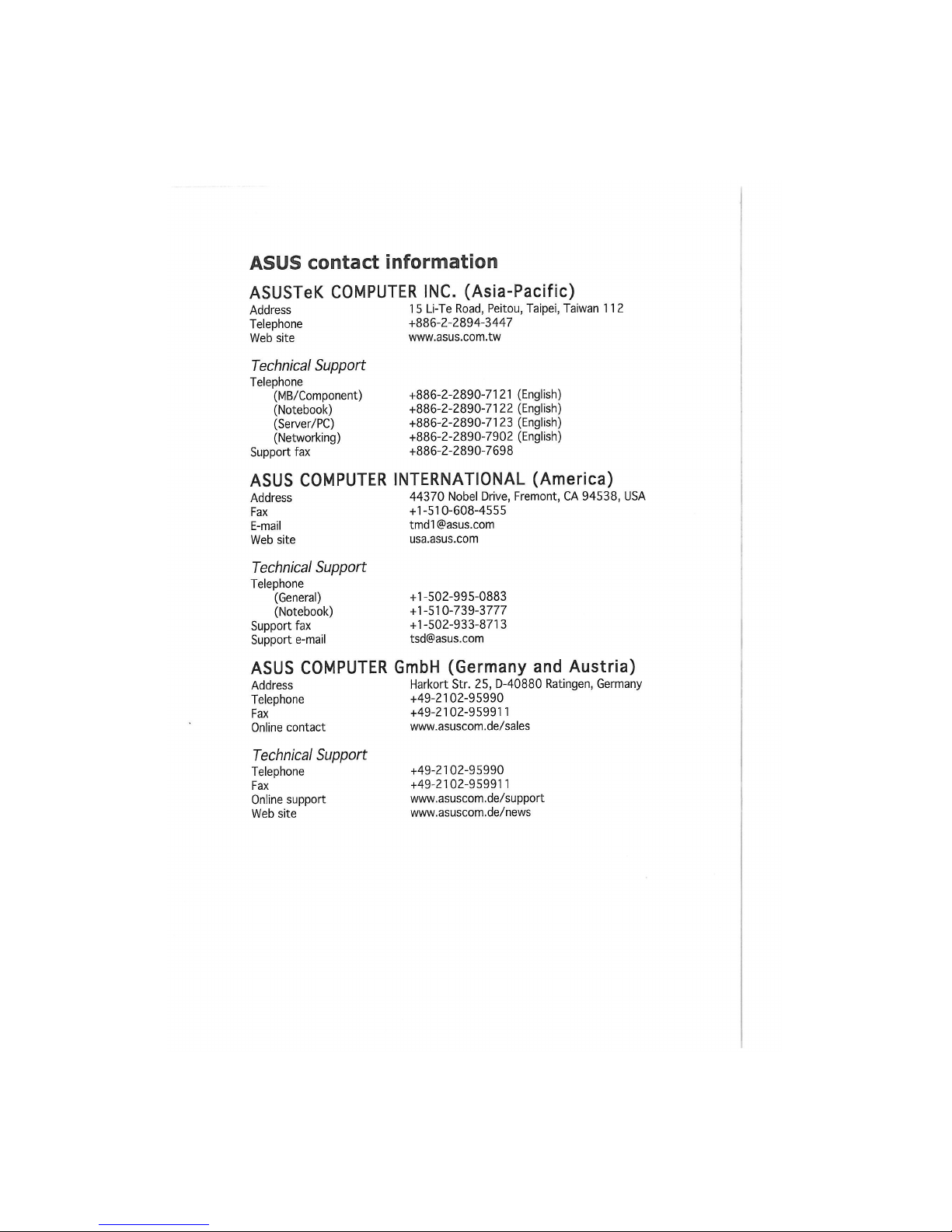
ASUS contact information
ASUSTeK COMPUTER INC. (Asia-Pacific)
Address 15 Li-Te Road, Peitou, Taipei, Taiwan 112
Telephone +886-2-2894-3447
Web site www.asus.com.tw
Technical Support
Telephone
(MB/Component) +886-2-2890-7121 (English)
(Notebook) +886-2-2890-7122 (English)
(Server/PC) +886-2-2890-7123 (English)
(Networking) +886-2-2890-7902 (English)
Support fax +886-2-2890-7698
ASUS COMPUTER INTERNATIONAL (America)
Address 44370 Nobel Drive, Fremont, CA 94538, USA
Fax +1-510-608-4555
E-mail tmd1@asus.com
Web site usa.asus.com
Technical Support
Telephone
(General) +1-502-995-0883
(Notebook) +1-510-739-3777
Support fax +1-502-933-8713
Support e-mail tsd@asus.com
ASUS COMPUTER GmbH (Germany and Austria)
Address Harkort Str. 25, D-40880 Ratingen, Germany
Telephone +49-2102-95990
Fax +49-2102-959911
Online contact www.asuscom.de/sales
Technical Support
Telephone
Fax
Online support
Web site
+49-2102-95990
+49-2102-959911
www.asuscom.de/support
www.asuscom.de/news
P5S-TWM
E2245
First Edition VI
February 2005
Copyright © 2005 ASUSTeK COMPUTER INC. All Rights Reserved.
No part of this manual, including the products and software described in it, may be reproduced,
transmitted, transcribed, stored in a retrieval system, or translated into any language in any form
or by any means, except documentation kept by the purchaser for backup purposes, without the
express written permission of ASUSTeK COMPUTER INC. ("ASUS").
Product warranty or service will not be extended if: (1) the product is repaired, modified or
altered, unless such repair, modification of alteration is authorized in writing by ASUS; or (2)
the serial number of the product is defaced or missing.
ASUS PROVIDES THIS MANUAL "AS IS" WITHOUT WARRANTY OF ANY KIND, EITHER
EXPRESS OR IMPLIED, INCLUDING BUT NOT LIMITED TO THE IMPLIED WARRANTIES
OR CONDITIONS OF MERCHANTABILITY OR FITNESS FOR A PARTICULAR PURPOSE.
IN NO EVENT SHALL ASUS, ITS DIRECTORS, OFFICERS, EMPLOYEES OR AGENTS BE
LIABLE FOR ANY INDIRECT, SPECIAL, INCIDENTAL, OR CONSEQUENTIAL DAMAGES
(INCLUDING DAMAGES FOR LOSS OF PROFITS, LOSS OF BUSINESS, LOSS OF USE
OR DATA, INTERRUPTION OF BUSINESS AND THE LIKE), EVEN IF ASUS HAS BEEN
ADVISED OF THE POSSIBILITY OF SUCH DAMAGES ARISING FROM ANY DEFECT OR
ERROR IN THIS MANUAL OR PRODUCT
SPECIFICATIONS AND INFORMATION CONTAINED IN THIS MANUAL ARE FURNISHED
FOR INFORMATIONAL USE ONLY, AND ARE SUBJECT TO CHANGE AT ANY TIME
WITHOUT NOTICE, AND SHOULD NOT BE CONSTRUED AS A COMMITMENT BY
ASUS. ASUS ASSUMES NO RESPONSIBILITY OR LIABILITY FOR ANY ERRORS OR
INACCURACIES THAT MAY APPEAR IN THIS MANUAL, INCLUDING THE PRODUCTS
AND SOFTWARE DESCRIBED IN IT.
Products and corporate names appearing in this manual may or may not be registered
trademarks or copyrights of their respective companies, and are used only for identification or
explanation and to the owners' benefit, without intent to infringe.
ii
Contents
Notices
v
Safety information vi
P5G-TVM specifications summary vii
Chapter 1: Product introduction
1.1 Before you proceed 1-2
1.2 Motherboard overview
1
-3
1.2.1 Placement direction
1
-3
1.2.2 Screw holes 1-3
1.2.3 Motherboard layout
1
-4
1.2.4 Layout contents
1
-5
1.3 Central Processing Unit (CPU)
1
-7
1.3.1 Installing the CPU 1-7
1.3.2 Installing the CPU heatsink and fan
1
-10
1.3.3 Uninstalling the CPU heatsink and fan
1
-12
1.4 System memory 1-14
1.4.1 DIMM sockets location 1-14
1.4.2 Memory Configurations 1-14
1.4.3 Installing a DIMM 1-16
1.4.4 Removing a DIMM 1-16
1.5 Expansion slots 1-17
1.5.1 Installing an expansion card
1
-17
1.5.2 Configuring an expansion card
1
-17
1.5.3 Interrupt assignments 1-18
1.5.4 PCI slots 1-19
1.5.5 PCI Express xl 6 slot 1-19
1.6 Jumpers 1-20
1.7 Connectors 1-22
1.7.1 Rear panel connectors 1-22
1.7.2 Internal connectors
1
-24
Chapter 2: BIOS Setup
2.1 BIOS setup program 2-2
2.2 BIOS menu screen 2-3
2.2.1 Menu bar 2-3
2.2.2 Legend bar 2-4
Contents
2.2.3 Menu items 2-4
2.2.4 Sub-menu items 2-4
2.2.5 Configuration fields 2-4
2.2.6 Pop-up window 2-5
2.2.7 General help 2-5
2.3 Main menu 2-6
2.3.1 System Time 2-6
2.3.2 System Date 2-6
2.3.3 Legacy Diskette A 2-6
2.3.4 Primary and Secondary IDE Master/Slave 2-7
2.3.5 HDD SMART Monitoring 2-8
2.3.6 Installed Memory 2-8
2.3.7 Usable Memory 2-8
2.4 Advanced Menu 2-9
2.4.1 CPU Configuration 2-9
2.4.2 Memory Configuration 2-11
2.4.3 Chipset 2-12
2.4.4 PCIPnP 2-13
2.4.5 Onboard Device Configuration 2-14
2.4.6 USB Configuration 2-16
2.5 Power menu 2-17
2.5.1 ACPI Suspend Type 2-17
2.5.2 ACPI APCi Support 2-17
2.5.3 АРМ Configuration 2-18
2.5.4 Hardware Monitor 2-20
2.6 Boot menu 2-21
2.6.1 Boot Device Priority 2-22
2.6.2 Removable Drives 2-23
2.6.3 Hard Disk Drives 2-23
2.6.4 Network Boot Priority 2-24
2.6.5 Boot Settings Configuration 2-24
2.6.6 Security 2-26
2.7 Exit menu 2-28
Notices
Federal Communications Commission Statement
This device complies with Part 1 5 of the FCC Rules. Operation is subject to
the following two conditions:
• This device may not cause harmful interference, and
• This device must accept any interference received including
interference that may cause undesired operation.
This equipment has been tested and found to comply with the limits for a
Class В digital device, pursuant to Part 1 5 of the FCC Rules. These limits
are designed to provide reasonable protection against harmful interference
in a residential installation. This equipment generates, uses and can radiate
radio frequency energy and, if not installed and used in accordance with
manufacturer's instructions, may cause harmful interference to radio
communications. However, there is no guarantee that interference will
not occur in a particular installation. If this equipment does cause harmful
interference to radio or television reception, which can be determined by
turning the equipment off and on, the user is encouraged to try to correct
the interference by one or more of the following measures:
• Reorient or relocate the receiving antenna.
о Increase the separation between the equipment and receiver.
• Connect the equipment to an outlet on a circuit different from that to
which the receiver is connected.
• Consult the dealer or an experienced radio/TV technician for help.
v The use of shielded cables for connection of the monitor to the graphics
i С card is required to assure compliance with FCC regulations. Changes
/ or modifications to this unit not expressly approved by the party
responsible for compliance could void the user's authority to operate
this equipment.
Canadian Department of Communications Statement
This digital apparatus does not exceed the Class В limits for radio noise
emissions from digital apparatus set out in the Radio Interference
Regulations of the Canadian Department of Communications.
This class В digital apparatus complies with Canadian
ICES-003.
Safety information
Electrical safety
о To prevent electrical shock hazard, disconnect the power cable from
the electrical outlet before relocating the system.
• When adding or removing devices to or from the system, ensure that
the power cables for the devices are unplugged before the signal
cables are connected. If possible, disconnect all power cables from the
existing system before you add a device.
• Before connecting or removing signal cables from the motherboard,
ensure that all power cables are unplugged.
• Seek professional assistance before using an adapter or extension
cord. These devices could interrupt the grounding circuit.
• Make sure that your power supply is set to the correct voltage in your
area. If you are not sure about the voltage of the electrical outlet you
are using, contact your local power company.
о If the power supply is broken, do not try to fix it by yourself. Contact
a qualified service technician or your retailer.
Operation safety
• Before installing the motherboard and adding devices on it, carefully
read all the manuals that came with the package.
• Before using the product, make sure all cables are correctly connected
and the power cables are not damaged. If you detect any damage,
contact your dealer immediately.
о To avoid short circuits, keep paper clips, screws, and staples away from
connectors, slots, sockets and circuitry.
• Avoid dust, humidity, and temperature extremes. Do not place the
product in any area where it may become wet.
• Place the product on a stable surface.
• If you encounter technical problems with the product, contact a
qualified service technician or your retailer.
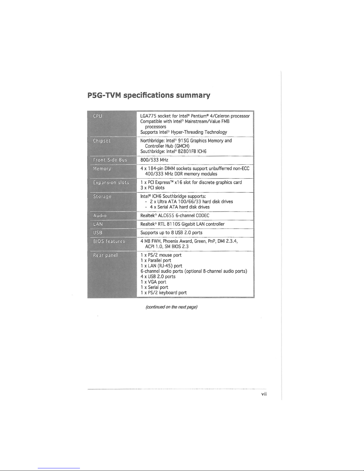
P5G-TVM specifications summary
CPU
LGA775 socket for Intel® Pentium® 4/Celeron processor
Compatible with Intel0 Mainstream/Value FMB
processors
Supports Intel-' Hyper-Threading Technology
Chipset
Northbridge: Intel'1 91
5G Graphics Memory and
Controller Hub (GMCH)
Southbridge: Intel'" 82801FB ICH6
Front Side Bus
800/533 MHz
Memory 4 x 184-pin DIMM sockets support unbufferred non-ECC
400/333 MHz DDR memory modules
Expansion slots 1 x PCI Express™ xl 6 slot for discrete graphics card
3 x PCI slots
Storage
Intel® ICH6 Southbridge supports:
- 2 x Ultra ATA 100/66/33 hard disk drives
- 4 x Serial ATA hard disk drives
Audio
Realtek* ALC655 6-channel CODEC
LAN
Realtek* RTL 8110S Gigabit LAN controller
USB
Supports up to 8 USB 2.0 ports
BIOS features
4 MB FWH, Phoenix Award, Green, PnP, DMI 2.3.4,
ACPI 1.0, SM BIOS 2.3
Rear panel
1 x PS/2 mouse port
1 x Parallel port
1 x LAN (RJ-45) port
6-channel audio ports (optional 8-channel audio ports)
4 x USB 2.0 ports
1 x VGA port
1 x Serial port
1 x PS/2 keyboard port
(continued on the next page)
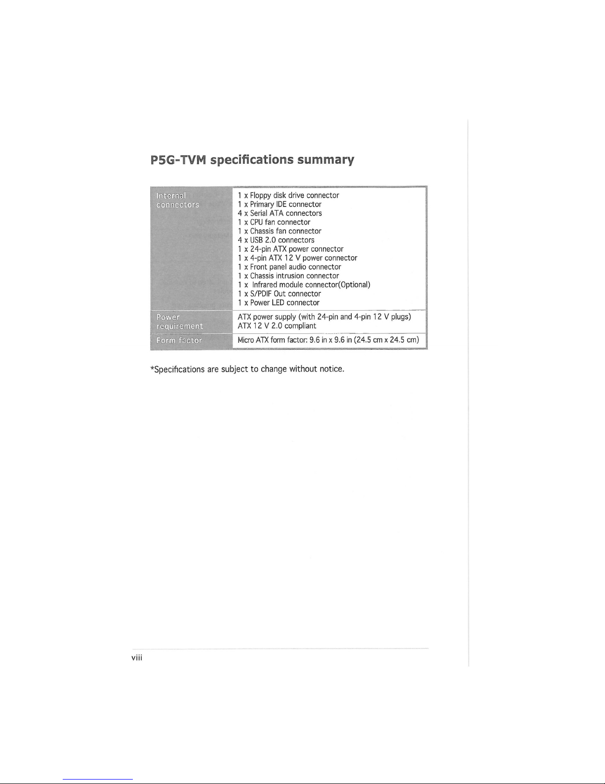
P5G-TVM specifications summary
Internal
1 x Floppy disk drive connector
connectors
1 x Primary IDE connector
4 x Serial ATA connectors
1 x CPU fan connector
1 x Chassis fan connector
4 x USB 2.0 connectors
1 x 24-pin ATX power connector
1 x 4-pin ATX 12 V power connector
1 x Front panel audio connector
1 x Chassis intrusion connector
1 x Infrared module connector(Optional)
1 x S/PDIF Out connector
1 x Power LED connector
Power
ATX power supply (with 24-pin and 4-pin 12 V plugs)
requirement
ATX 12 V 2.0 compliant
Form factor
Micro ATX form factor: 9.6 in x 9.6 in (24.5 cm x 24.5 cm)
*Specifications are subject to change without notice.
This chapter describes the motherboard
features and the new technologies
it supports.
[Piredlpctt
introduction
ASUS P5G-TVM
1-1 5
1.1 Before you proceed
Take note of the following precautions before you install components into
the system.
/ \
I
Unplug the power cord from the wall socket before touching any
component.
Use a grounded wrist strap or touch a safely grounded object or
a metal object, such as the power supply case, before handling
components to avoid damaging them due to static electricity.
Hold components by the edges to avoid touching the ICs on them.
Whenever you uninstall any component, place it on a grounded
antistatic pad or in the bag that came with the component.
Before you install or remove any component, ensure that the ATX
power supply is switched off or the power cord is detached from
the power supply. Failure to do so may cause severe damage to the
motherboard, peripherals, and/or components.
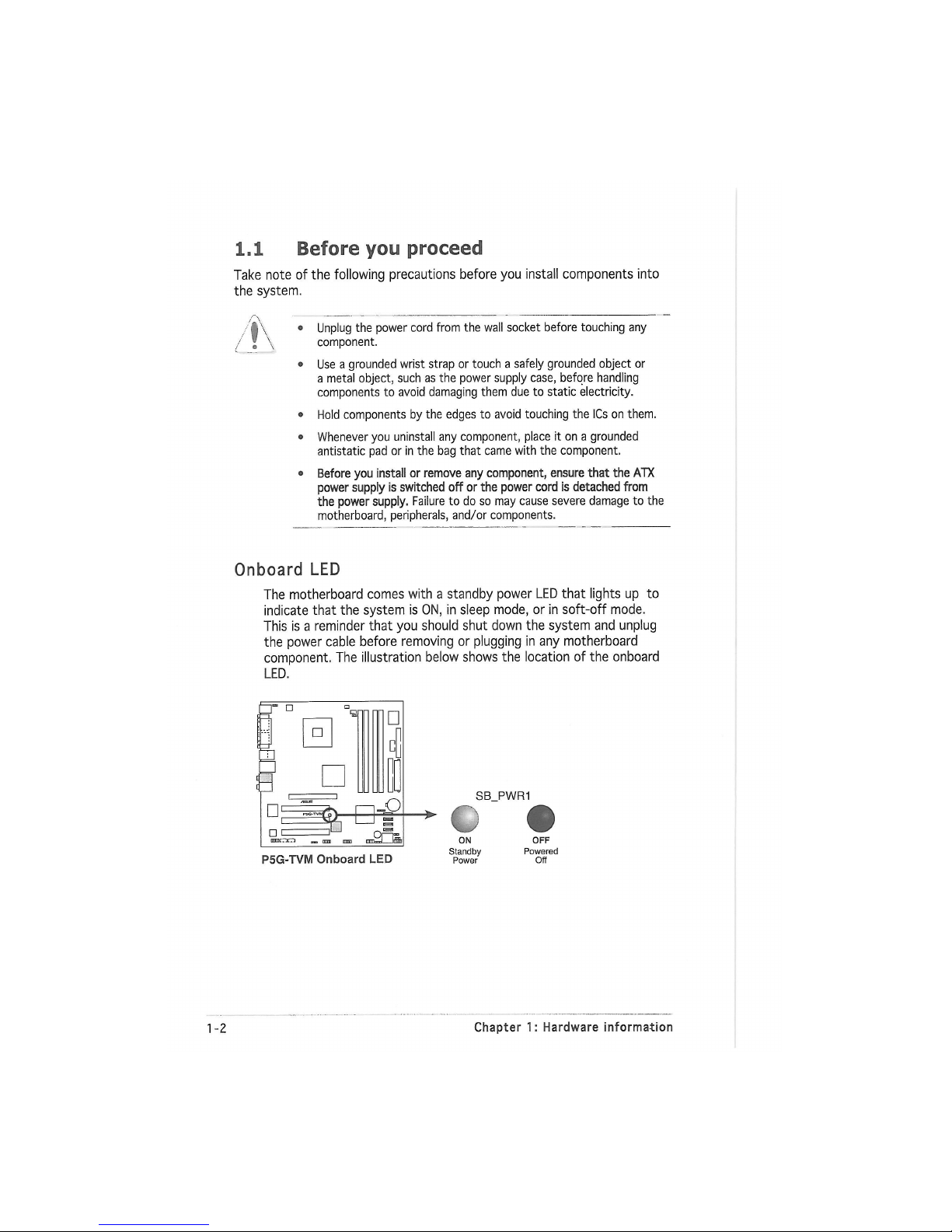
Onboard LED
The motherboard comes with a standby power LED that lights up to
indicate that the system is ON, in sleep mode, or in soft-off mode.
This is a reminder that you should shut down the system and unplug
the power cable before removing or plugging in any motherboard
component. The illustration below shows the location of the onboard
LED.
P5G-TVM Onboard LED
SB_PWR1
ON
Standby
Power
OFF
Powered
Off
1-2
Chapter 1: Hardware information
1.2 Motherboard overview
Before you install the motherboard, study the configuration of your chassis
to ensure that the motherboard fits into it.
Make sure to unplug the power cord before installing or removing the
motherboard. Failure to do so can cause you physical injury and damage
motherboard components.
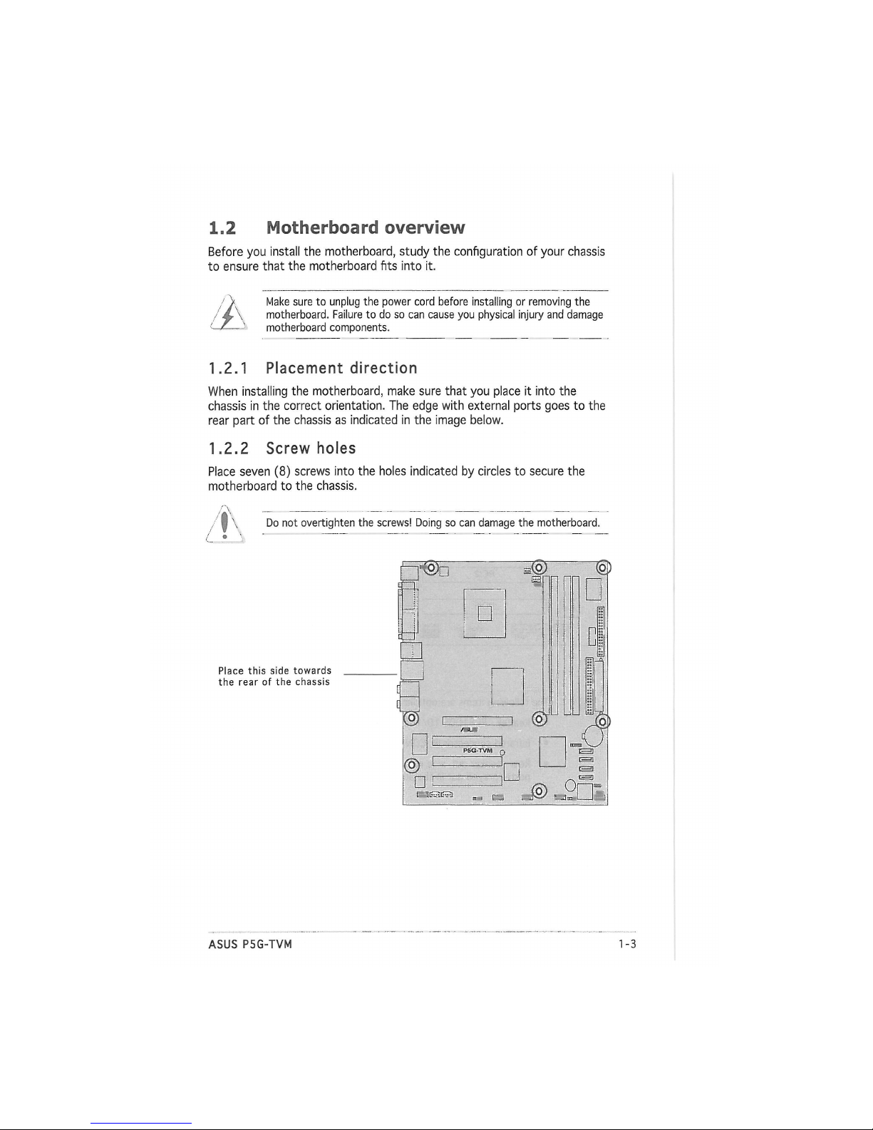
1.2.1 Placement direction
When installing the motherboard, make sure that you place it into the
chassis in the correct orientation. The edge with external ports goes to the
rear part of the chassis as indicated in the image below.
1.2.2 Screw holes
Place seven (8) screws into the holes indicated by circles to secure the
motherboard to the chassis.
Do not overtighten the screws! Doing so can damage the motherboard.
Place this side towards
the rear of the chassis
ASUS P5G-TVM
1-1 5
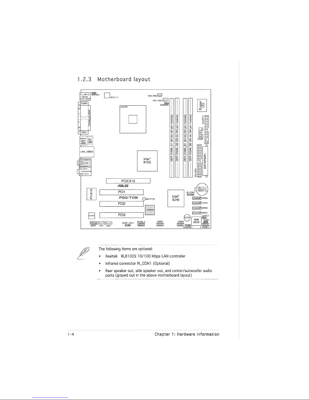
1.2.3 Motherboard layout
F. жт is
T:
Mouse
B:K* ooard
Q
«Ы
I,B
• VGA1I
CPU_FAN1 U
EIH
FANPWR1
PCIEX16
/HLS'
PCI1
P5G-TVM
O
nu
нш
PCI2
PCI3
lii
COM2
Intel"
1
ICH6
с
l| ГАТАЗ
с l|SATA1
AAFP1 CD1 AUX1
IE1394.2
ШИЗ
USB56
иппш
The following items are optional:
o Realtek RL8100S 10/100 Mbps LAN controller
• Infrared connector IR_C0N1 (Optional)
• Rear speaker out, side speaker out, and center/subwoofer audio
ports (grayed out in the above motherboard layout)
1-14 Chapter 1: Hardware information
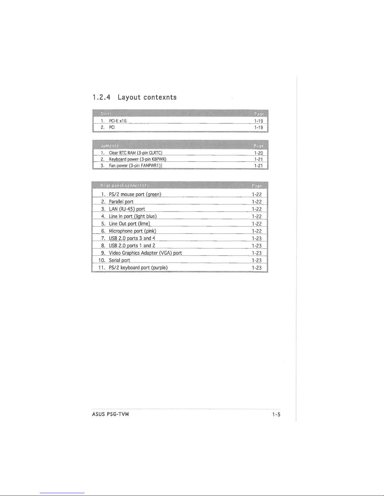
1.2.4 Layout contexnts
Slots
Page
1. PCI-E xl 6
1-19
2. PCI
1-19
! Jumpers
Page
1. Clear RTC RAM (3-pin CLRTC)
1-20
2. Keyboard power (3-pin KBPWR)
1-21
3. Fan power (3-pin FANPWR1))
1-21
Rear panel connectors
Page
1. PS/2 mouse port (qreen)
1-22
2. Parallel port
1-22
3. LAN (RJ-45) port
1-22
4. Line In port (liqht blue)
1-22
5. Line Out port (lime)
1-22
6. Microphone port (pink)
1-22
7. USB 2.0 ports 3 and 4
1-23
8. USB 2.0 ports 1 and 2
1-23
9. Video Graphics Adapter (VGA) port
1-23
10. Serial port
1-23
11. PS/2 keyboard port (purple)
1-23
ASUS P5G-TVM
1-1 5
' ...... '•. v • Ш
H?
1 i.
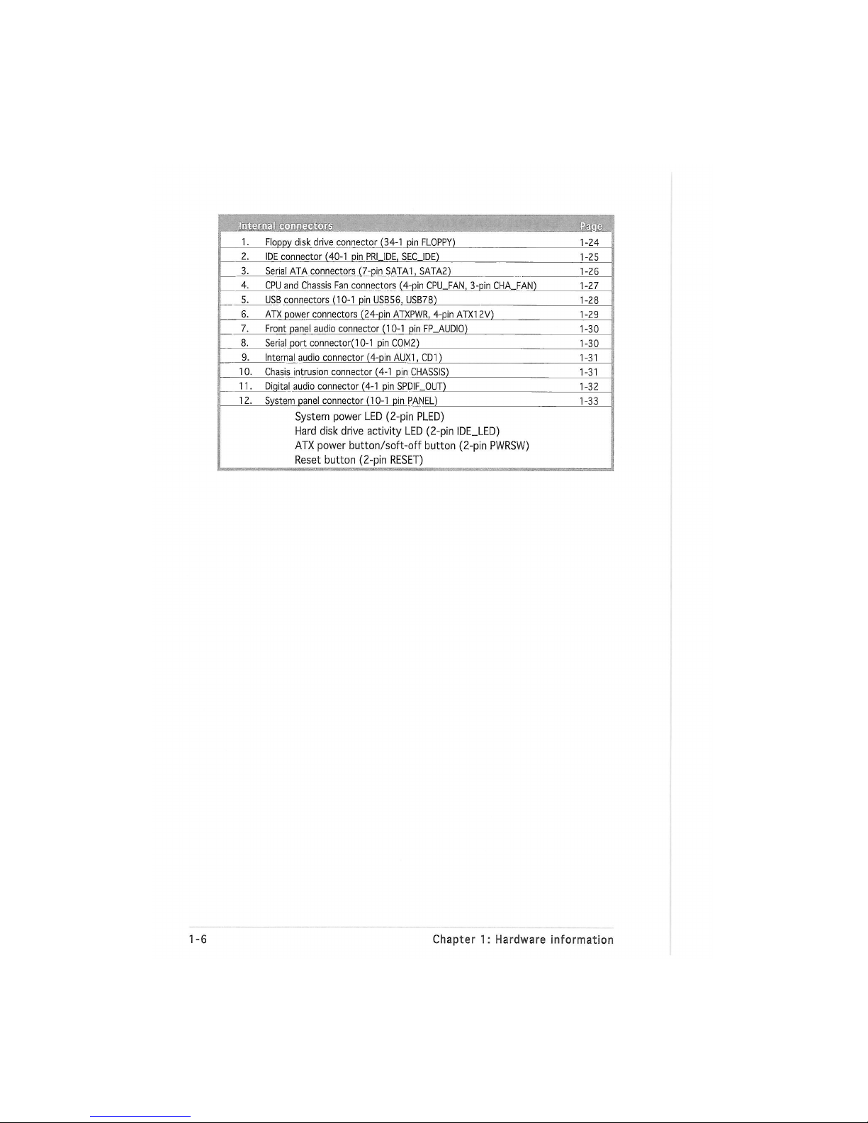
Floppy disk drive connector (34-1 pin FLOPPY)
1-24
2.
IDE connector (40-1 pin PRUDE, SECJDE)
1-25
3. Serial ATA connectors (7-pin SATA1, SATA2)
1-26
4.
CPU and Chassis Fan connectors (4-pin CPU_FAN, 3-pin CHA_FAN)
1-27
5.
USB connectors (10-1 pin USB56, USB78)
1-28
6. ATX power connectors (24-pin ATXPWR, 4-pin ATX1 2V)
1-29
7.
Front panel audio connector (10-1 pin FP_AUDIO)
1-30
8. Serial port connector(l
0-1
pin COM2)
1-30
9. Internal audio connector (4-pin AUX1, CD1)
1-31
10. Chasis intrusion connector (4-1 pin CHASSIS)
1-31
11.
Diqital audio connector (4-1 pin SPDIF_OUT)
1-32
12.
System panel connector (10-1 pin PANEL)
1-33
System power LED (2-pin PLED)
Hard disk drive activity LED (2-pin IDE_LED)
ATX power button/soft-off button (2-pin PWRSW)
Reset button (2-pin RESET)
1-6 Chapter 1: Hardware information
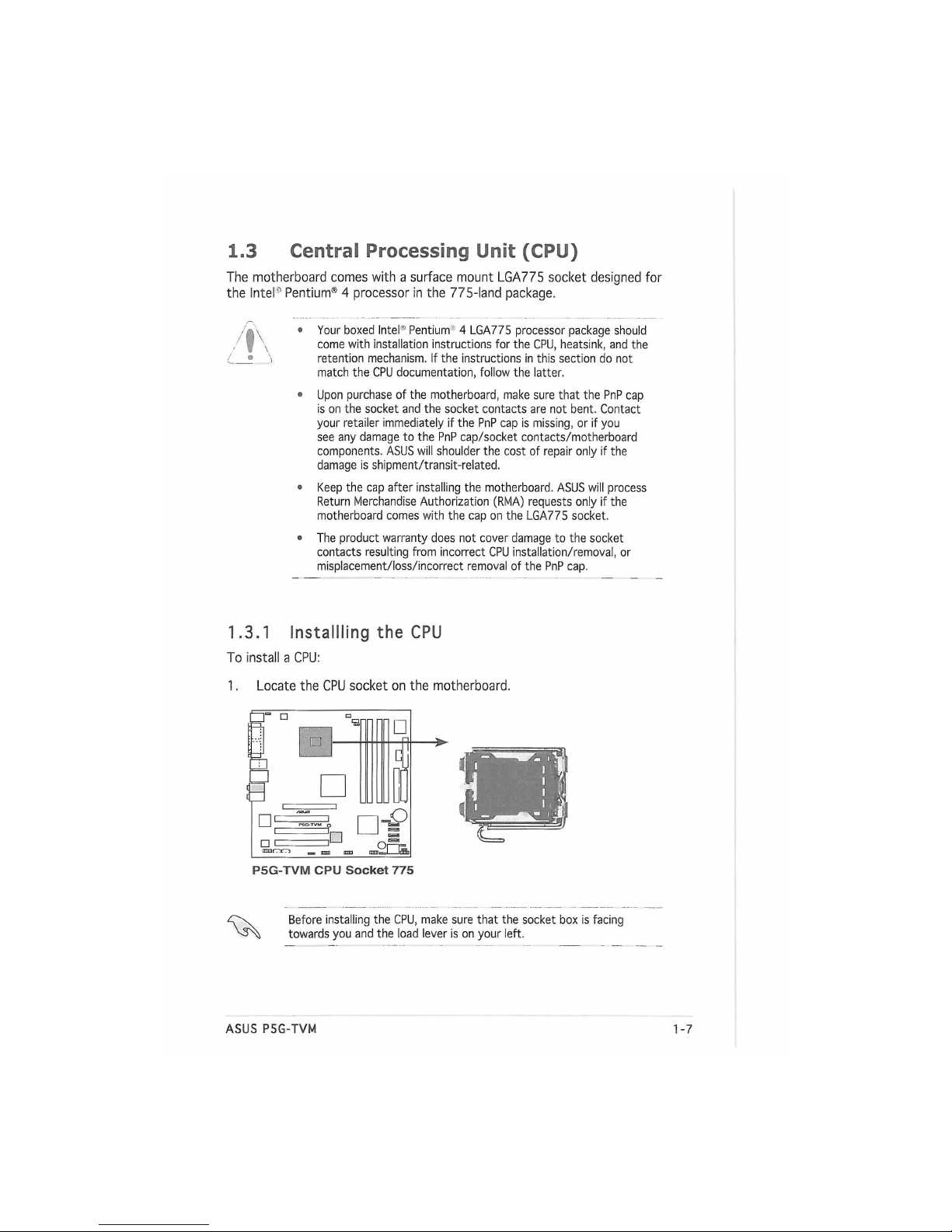
1.3 Central Processing Unit (CPU)
The motherboard comes with a surface mount LGA775 socket designed for
the Intel0 Pentium® 4 processor in the 775-land package.
• Your boxed Intel1 Pentium 4 LGA775 processor package should
come with installation instructions for the CPU, heatsink, and the
retention mechanism. If the instructions in this section do not
match the CPU documentation, follow the latter.
• Upon purchase of the motherboard, make sure that the PnP cap
is on the socket and the socket contacts are not bent. Contact
your retailer immediately if the PnP cap is missing, or if you
see any damage to the PnP cap/socket contacts/motherboard
components. ASUS will shoulder the cost of repair only if the
damage is shipment/transit-reiated.
• Keep the cap after installing the motherboard. ASUS will process
Return Merchandise Authorization (RMA) requests only if the
motherboard comes with the cap on the LGA775 socket.
• The product warranty does not cover damage to the socket
contacts resulting from incorrect CPU installation/removal, or
misplacement/loss/incorrect removal of the PnP cap.
1.3.1 Installing the CPU
To install a CPU:
1. Locate the CPU socket on the motherboard.
P5G-TVM CPU Socket 775
Before installing the CPU, make sure that the socket box is facing
towards you and the load lever is on your left.
ASUS P5G-TVM
1-1 5
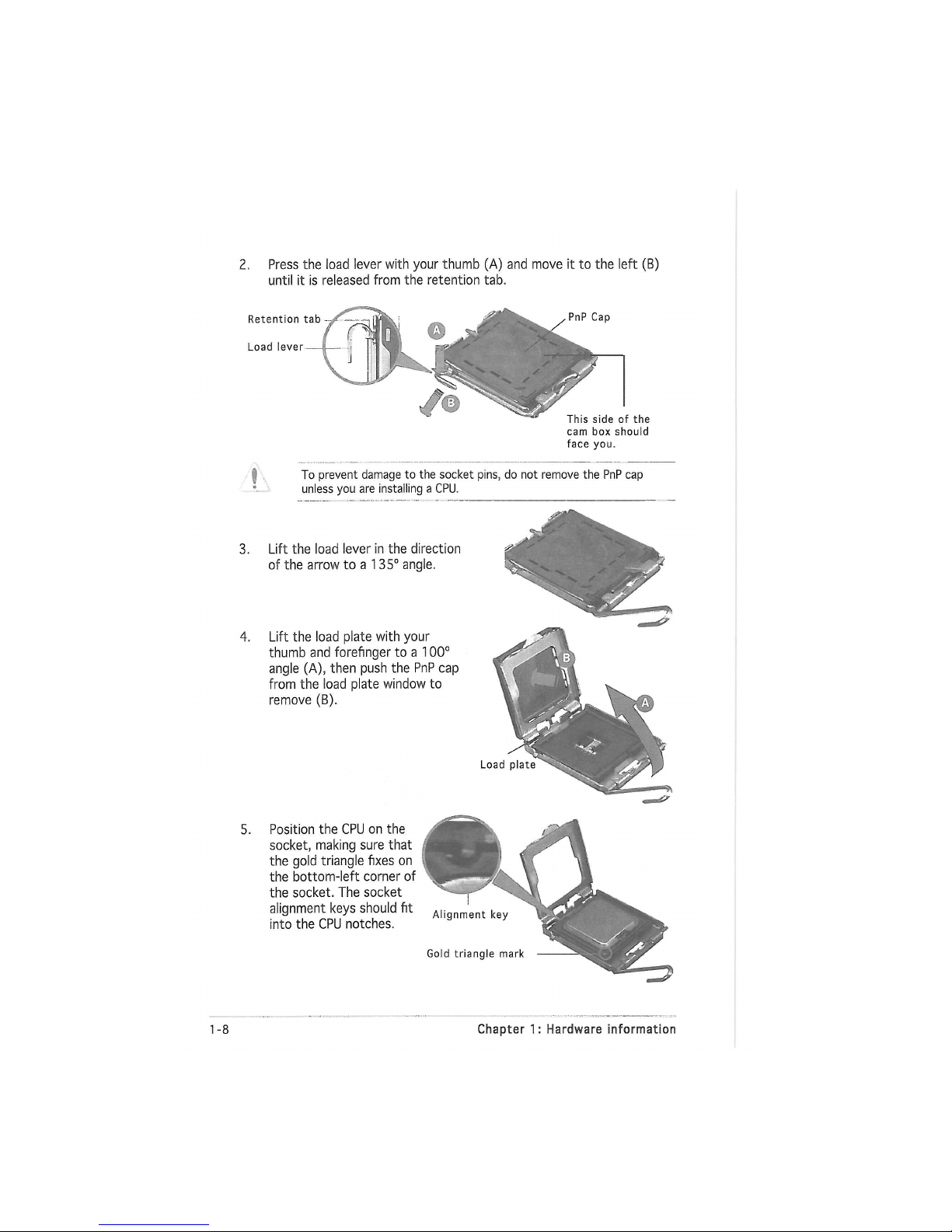
2. Press the load lever with your thumb (A) and move it to the left (B)
until it is released from the retention tab.
Retention tab
Load lever
the
cam box should
face you.
4. Lift the load plate with your
thumb and forefinger to a 100°
angle (A), then push the PnP cap
from the load plate window to
remove (B).
5. Position the CPU on the
socket, making sure that
the gold triangle fixes on
the bottom-left corner of
the socket. The socket
alignment keys should fit
into the CPU notches.
1-18 Chapter 1: Hardware information
To prevent damage to the socket pins, do not remove the PnP cap
unless you are installing a CPU.
3. Lift the load lever in the direction
of the arrow to a 135° angle.
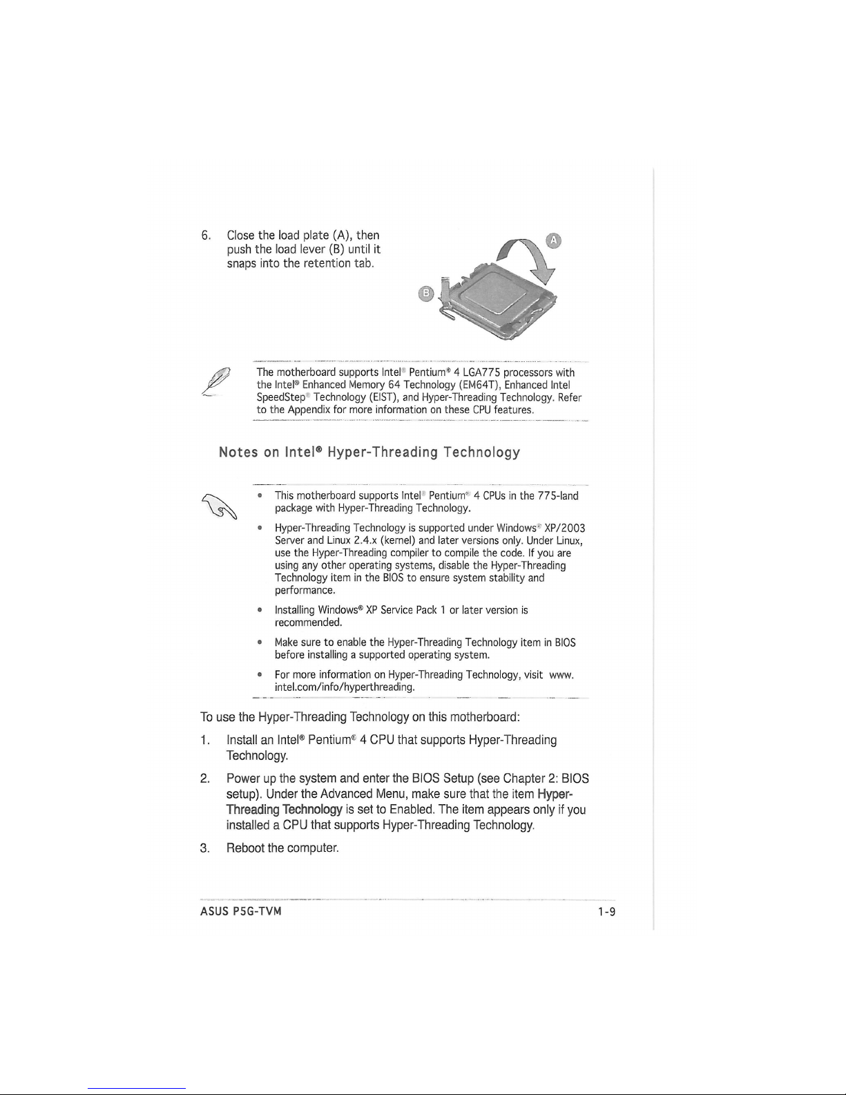
6, Close the load plate (A), then
push the load lever (B) until it
snaps into the retention tab.
The motherboard supports Intel Pentium® 4 LGA775 processors with
the Intel® Enhanced Memory 64 Technology (EM64T), Enhanced Intel
SpeedStep Technology (EIST), and Hyper-Threading Technology. Refer
to the Appendix for more information on these CPU features.
Notes on Intel® Hyper-Threading Technology
• This motherboard supports Intel Pentium" 4 CPUs in the 775-land
package with Hyper-Threading Technology.
• Hyper-Threading Technology is supported under Windows1 XP/2003
Server and Linux 2.4.x (kernel) and later versions only. Under Linux,
use the Hyper-Threading compiler to compile the code. If you are
using any other operating systems, disable the Hyper-Threading
Technology item in the BIOS to ensure system stability and
performance.
• Installing Windows® XP Service Pack 1 or later version is
recommended.
• Make sure to enable the Hyper-Threading Technology item in BIOS
before installing a supported operating system.
• For more information on Hyper-Threading Technology, visit www.
intel.com/info/hyperthreading.
To use the Hyper-Threading Technology on this motherboard:
1. Install an Intel® Pentium1 4 CPU that supports Hyper-Threading
Technology.
2. Power up the system and enter the BIOS Setup (see Chapter 2: BIOS
setup). Under the Advanced Menu, make sure that the item Hyper-
Threading
Technology is set to Enabled. The item appears only if you
installed a CPU that supports Hyper-Threading Technology.
3. Reboot the computer.
ASUS P5G-TVM 1-1 5
1.3.2 Installing the CPU heatsink and fan
The Inter Pentium11 4 LGA775 processor requires a specially designed
heatsink and fan assembly to ensure optimum thermal condition and
performance.
C\ • Install the motherboard to the chassis before you install the CPU fan
and heatsink assembly.
• When you buy a boxed Intel® Pentium'1 4 processor, the package
includes the CPU fan and heatsink assembly. If you buy a
CPU separately, make sure that you use only InteKcertified
multi-directional heatsink and fan.
о Your Intel Pentium1"1 4 LGA775 heatsink and fan assembly comes in
a push-pin design and requires no tool to install it.
Make sure that you have installed the motherboard to the chassis before
you install the CPU fan and heatsink assembly.
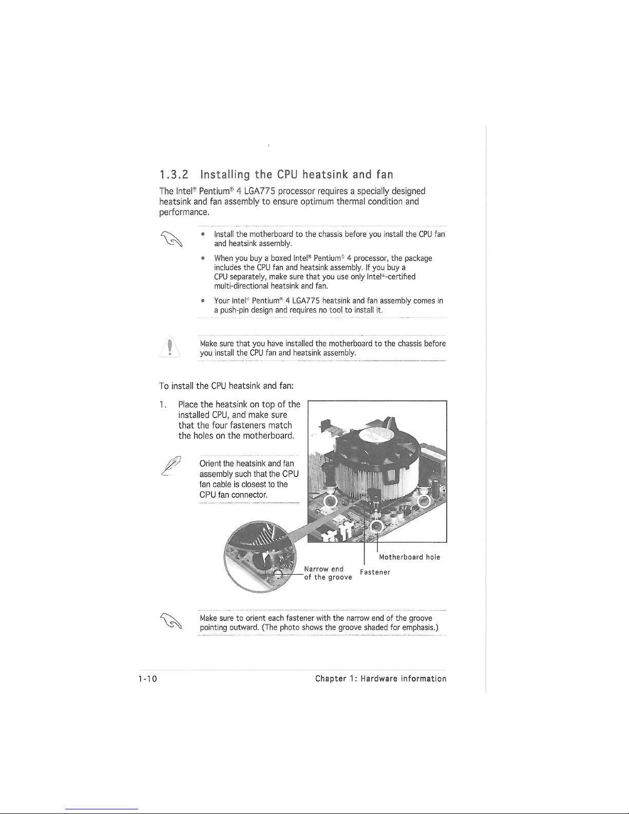
To install the CPU heatsink and fan:
1. Place the heatsink on top of the
installed CPU, and make sure
that the four fasteners match
the holes on the motherboard.
Orient the heatsink and fan
assembly such that the CPU
fan cable is closest to the
CPU fan connector.
Motherboard hole
Fastener
Narrow end
of the groove
Make sure to orient each fastener with the narrow end of the groove
pointing outward. (The photo shows the groove shaded for emphasis.)
1-10 Chapter 1: Hardware information
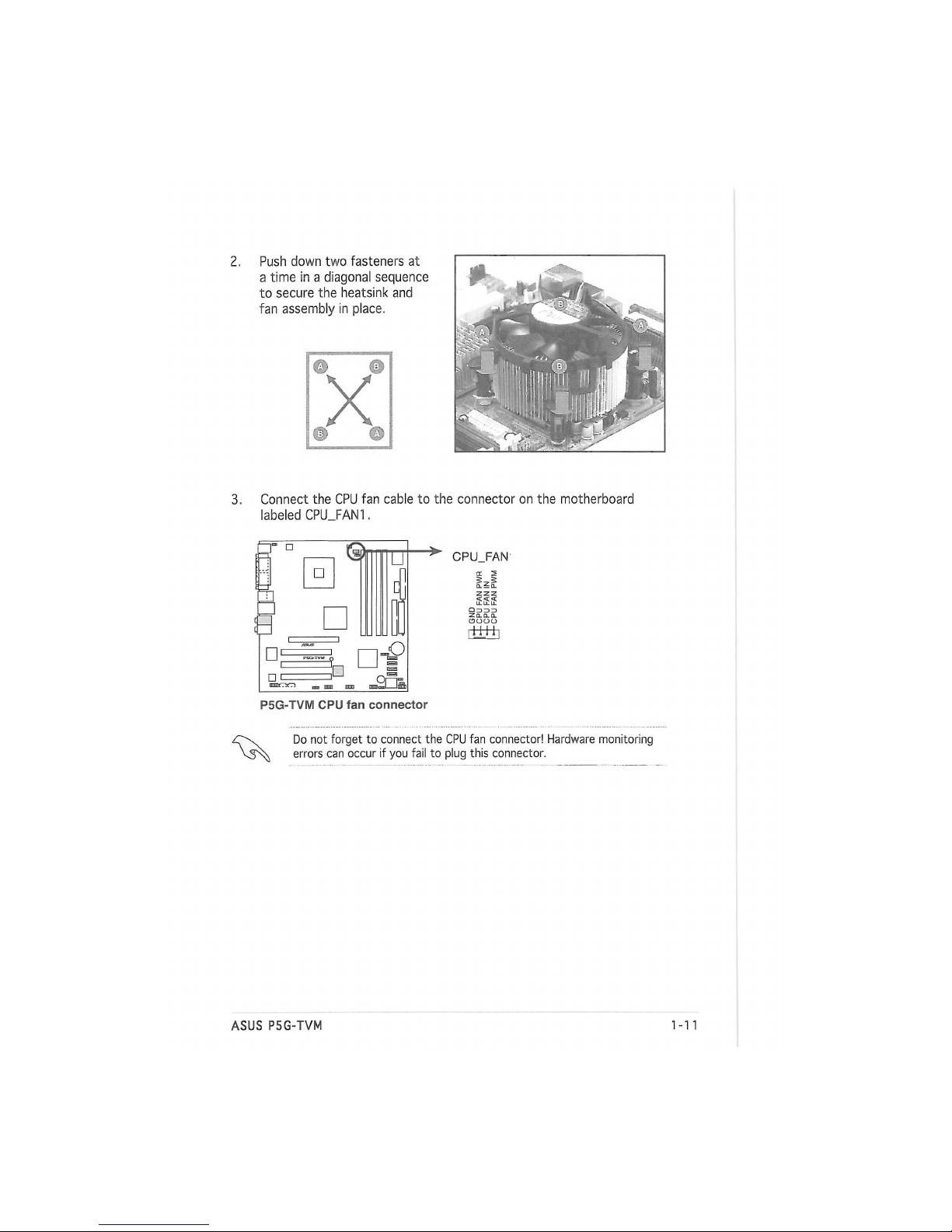
2. Push down two fasteners at
a time in a diagonal sequence
to secure the heatsink and
fan assembly in place.
3. Connect the CPU fan cable to the connector on the motherboard
labeled CPU_FAN1.
•
3
•
•
•
U
„О
CPU_FAN'
пШ+i
P5G-TVM CPU fan connector
Do not forget to connect the CPU fan connector! Hardware monitoring
errors can occur if you fail to plug this connector.
ASUS P5G-TVM
1-1 5
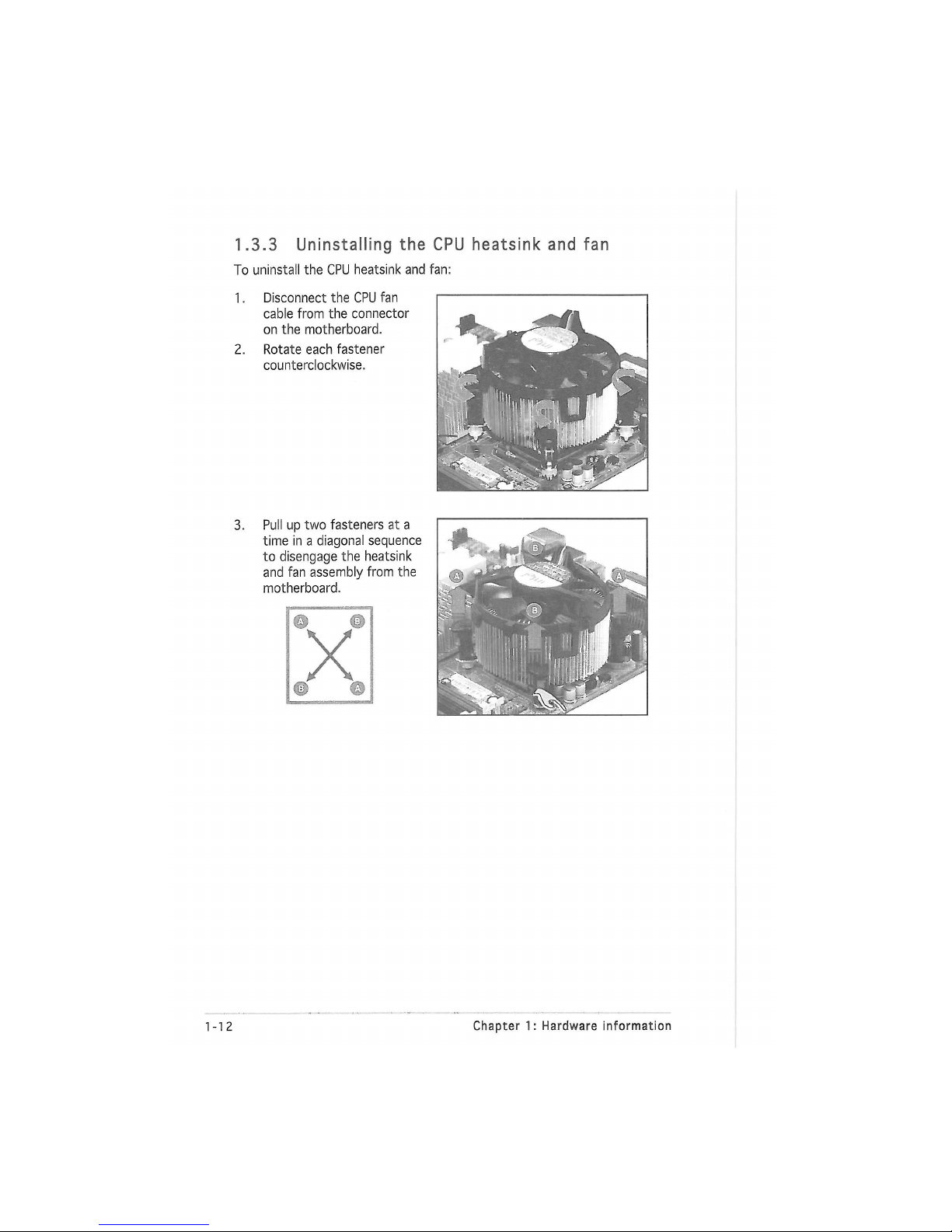
1.3.3 Uninstalling the CPU heatsink and fan
To uninstall the CPU heatsink and fan:
1. Disconnect the CPU fan
cable from the connector
on the motherboard.
2. Rotate each fastener
counterclockwise.
3.
Pull up two fasteners at a
time in a diagonal sequence
to disengage the heatsink
and fan assembly from the
motherboard.
1-12
Chapter 1: Hardware information
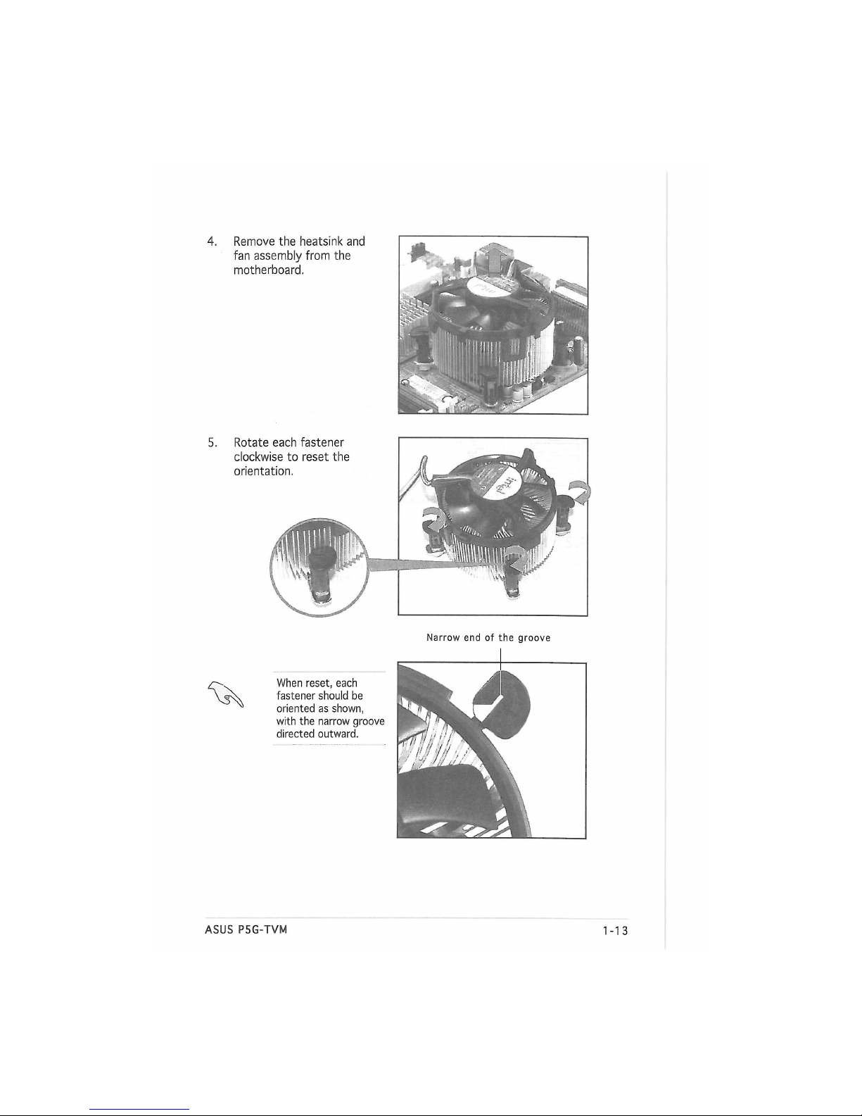
4. Remove the heatsink and
fan assembly from the
motherboard.
Narrow end of the groove
When reset, each
fastener should be
oriented as shown,
with the narrow groove
directed outward.
Rotate each fastener
clockwise to reset the
orientation.
ASUS P5G-TVM
1-1 5
 Loading...