


Asus P5GC-VM Pro User Manual

Motherboard
P5GC-VM PRO

ii
Copyright © 2007 ASUSTeK COMPUTER INC. All Rights Reserved.
No part of this manual, including the products and software described in it, may be reproduced,
transmitted, transcribed, stored in a retrieval system, or translated into any language in any form or by any
means, except documentation kept by the purchaser for backup purposes, without the express written
permission of ASUSTeK COMPUTER INC. (“ASUS”).
Product warranty or service will not be extended if: (1) the product is repaired, modied or altered, unless
such repair, modication of alteration is authorized in writing by ASUS; or (2) the serial number of the
product is defaced or missing.
ASUS PROVIDES THIS MANUAL “AS IS” WITHOUT WARRANTY OF ANY KIND, EITHER EXPRESS
OR IMPLIED, INCLUDING BUT NOT LIMITED TO THE IMPLIED WARRANTIES OR CONDITIONS OF
MERCHANTABILITY OR FITNESS FOR A PARTICULAR PURPOSE. IN NO EVENT SHALL ASUS, ITS
DIRECTORS, OFFICERS, EMPLOYEES OR AGENTS BE LIABLE FOR ANY INDIRECT, SPECIAL,
INCIDENTAL, OR CONSEQUENTIAL DAMAGES (INCLUDING DAMAGES FOR LOSS OF PROFITS,
LOSS OF BUSINESS, LOSS OF USE OR DATA, INTERRUPTION OF BUSINESS AND THE LIKE),
EVEN IF ASUS HAS BEEN ADVISED OF THE POSSIBILITY OF SUCH DAMAGES ARISING FROM ANY
DEFECT OR ERROR IN THIS MANUAL OR PRODUCT.
SPECIFICATIONS AND INFORMATION CONTAINED IN THIS MANUAL ARE FURNISHED FOR
INFORMATIONAL USE ONLY, AND ARE SUBJECT TO CHANGE AT ANY TIME WITHOUT NOTICE,
AND SHOULD NOT BE CONSTRUED AS A COMMITMENT BY ASUS. ASUS ASSUMES NO
RESPONSIBILITY OR LIABILITY FOR ANY ERRORS OR INACCURACIES THAT MAY APPEAR IN THIS
MANUAL, INCLUDING THE PRODUCTS AND SOFTWARE DESCRIBED IN IT.
Products and corporate names appearing in this manual may or may not be registered trademarks or
copyrights of their respective companies, and are used only for identication or explanation and to the
owners’ benet, without intent to infringe.
E3384
First Edition
September 2007

iii
Contents
Notices ......................................................................................................... vi
Safety information ..................................................................................... vii
About this guide ....................................................................................... viii
P5GC-VM PRO specications summary .................................................... x
Chapter 1: Product introduction
1.1 Welcome! ...................................................................................... 1-2
1.2 Package contents .........................................................................
1-2
1.3 Special features ............................................................................
1-2
1.3.1 Product highlights ...........................................................
1-2
1.3.2 Innovative ASUS features ...............................................
1-5
1.4 Before you proceed .....................................................................
1-6
1.5 Motherboard overview .................................................................
1-7
1.5.1 Placement direction ........................................................
1-7
1.5.2 Screw holes ....................................................................
1-7
1.5.3 Motherboard layout .........................................................
1-8
1.6 Central Processing Unit (CPU) ...................................................
1-9
1.6.1 Installling the CPU ..........................................................
1-9
1.6.2 Installling the CPU heatsink and fan .............................
1-12
1.6.3 Uninstalling the CPU heatsink and fan .........................
1-14
1.7 System memory .........................................................................
1-16
1.7.1 Overview .......................................................................
1-16
1.7.2 Memory congurations ..................................................
1-16
1.7.3 DDR2 Qualied Vendors List ........................................
1-17
1.7.4 Installing a DIMM ..........................................................
1-20
1.7.5 Removing a DIMM ........................................................
1-20
1.8 Expansion slots ..........................................................................
1-21
1.8.1 Installing an expansion card .........................................
1-21
1.8.2 Conguring an expansion card .....................................
1-21
1.8.3 Interrupt assignments ...................................................
1-22
1.8.4 PCI slots ........................................................................
1-23
1.8.5 PCI Express x1 slot .......................................................
1-23
1.8.6 PCI Express x16 slot .....................................................
1-23
1.9 Jumpers ......................................................................................
1-24

iv
Contents
1.10 Connectors ................................................................................. 1-26
1.10.1 Rear panel connectors ..................................................
1-26
1.10.2 Internal connectors .......................................................
1-27
Chapter 2: BIOS setup
2.1 Managing and updating your BIOS ............................................ 2-2
2.1.1 Creating a bootable oppy disk .......................................
2-2
2.1.2 ASUS EZ Flash utility ......................................................
2-3
2.1.3 AFUDOS utility ................................................................
2-4
2.1.4 ASUS CrashFree BIOS 2 utility ......................................
2-6
2.1.5 ASUS Update utility ........................................................
2-8
2.2 BIOS setup program ..................................................................
2-11
2.2.1 BIOS menu screen ........................................................
2-12
2.2.2 Menu bar .......................................................................
2-12
2.2.3 Navigation keys .............................................................
2-12
2.2.4 Menu items ...................................................................
2-13
2.2.5 Sub-menu items ............................................................
2-13
2.2.6 Conguration elds .......................................................
2-13
2.2.7 Pop-up window .............................................................
2-13
2.2.8 Scroll bar .......................................................................
2-13
2.2.9 General help .................................................................
2-13
2.3 Main menu ..................................................................................
2-14
2.3.1 System Time .................................................................
2-14
2.3.2 System Date .................................................................
2-14
2.3.3 Legacy Diskette A ........................................................
2-14
2.3.4 Primary, Third and Fourth IDE Master/Slave ................
2-15
2.3.5 IDE Conguration ..........................................................
2-16
2.3.6 System Information .......................................................
2-17
2.4 Advanced menu .........................................................................
2-18
2.4.1 JumperFree Conguration ............................................
2-18
2.4.2 USB Conguration ........................................................
2-20
2.4.3 CPU Conguration ........................................................
2-21
2.4.4 Chipset ..........................................................................
2-22
2.4.5 Onboard Devices Conguration ....................................
2-25
2.4.6 PCI PnP ........................................................................
2-26

v
Contents
2.5 Power menu ................................................................................ 2-28
2.5.1 Suspend Mode [Auto] ...................................................
2-28
2.5.2 ACPI 2.0 Support [Disabled] .........................................
2-28
2.5.3 ACPI APIC Support [Enabled] .......................................
2-28
2.5.4 APM Conguration ........................................................
2-29
2.5.5 Hardware Monitor .........................................................
2-31
2.6 Boot menu ..................................................................................
2-32
2.6.1 Boot Device Priority ......................................................
2-32
2.6.2 Hard Disk Drives ...........................................................
2-32
2.6.3 Boot Settings Conguration ..........................................
2-33
2.6.4 Security .........................................................................
2-34
2.7 Exit menu ....................................................................................
2-36
Chapter 3: Software support
3.1 Installing an operating system ................................................... 3-2
3.2 Support CD information ..............................................................
3-2
3.2.1 Running the support CD .................................................
3-2
3.2.2 Drivers menu ...................................................................
3-3
3.2.3 Utilities menu ..................................................................
3-4
3.2.4 ASUS Contact information ..............................................
3-5
Appendix: CPU features
A.1 Enhanced Intel SpeedStep® Technology (EIST) ........................A-2
A.2.1 System requirements ......................................................
A-2
A.2.2 Using the EIST ................................................................
A-2
A.2 Intel
®
Hyper-Threading Technology ...........................................A-4
Using the Hyper-Threading Technology ........................................ A-4

vi
Notices
Federal Communications Commission Statement
This device complies with Part 15 of the FCC Rules. Operation is subject to the
following two conditions:
•
This device may not cause harmful interference, and
•
This device must accept any interference received including interference that
may cause undesired operation.
This equipment has been tested and found to comply with the limits for a
Class B digital device, pursuant to Part 15 of the FCC Rules. These limits are
designed to provide reasonable protection against harmful interference in a
residential installation. This equipment generates, uses and can radiate radio
frequency energy and, if not installed and used in accordance with manufacturer’s
instructions, may cause harmful interference to radio communications. However,
there is no guarantee that interference will not occur in a particular installation. If
this equipment does cause harmful interference to radio or television reception,
which can be determined by turning the equipment off and on, the user is
encouraged to try to correct the interference by one or more of the following
measures:
•
Reorient or relocate the receiving antenna.
•
Increase the separation between the equipment and receiver.
•
Connect the equipment to an outlet on a circuit different from that to which the
receiver is connected.
•
Consult the dealer or an experienced radio/TV technician for help.
Canadian Department of Communications Statement
This digital apparatus does not exceed the Class B limits for radio noise emissions
from digital apparatus set out in the Radio Interference Regulations of the
Canadian Department of Communications.
This class B digital apparatus complies with Canadian
ICES-003.
The use of shielded cables for connection of the monitor to the graphics card is
required to assure compliance with FCC regulations. Changes or modications
to this unit not expressly approved by the party responsible for compliance
could void the user’s authority to operate this equipment.

vii
Safety information
Electrical safety
•
To prevent electrical shock hazard, disconnect the power cable from the
electrical outlet before relocating the system.
•
When adding or removing devices to or from the system, ensure that the
power cables for the devices are unplugged before the signal cables are
connected. If possible, disconnect all power cables from the existing system
before you add a device.
•
Before connecting or removing signal cables from the motherboard, ensure
that all power cables are unplugged.
•
Seek professional assistance before using an adapter or extension cord.
These devices could interrupt the grounding circuit.
•
Make sure that your power supply is set to the correct voltage in your area.
If you are not sure about the voltage of the electrical outlet you are using,
contact your local power company.
•
If the power supply is broken, do not try to x it by yourself. Contact a
qualied service technician or your retailer.
Operation safety
•
Before installing the motherboard and adding devices on it, carefully read all
the manuals that came with the package.
•
Before using the product, make sure all cables are correctly connected and the
power cables are not damaged. If you detect any damage, contact your dealer
immediately.
•
To avoid short circuits, keep paper clips, screws, and staples away from
connectors, slots, sockets and circuitry.
•
Avoid dust, humidity, and temperature extremes. Do not place the product in
any area where it may become wet.
•
Place the product on a stable surface.
•
If you encounter technical problems with the product, contact a qualied
service technician or your retailer.
This symbol of the crossed out wheeled bin indicates that the product (electrical
and electronic equipment, Mercury-containing button cell battery) should not
be placed in municipal waste. Check local regulations for disposal of electronic
products.

viii
About this guide
This user guide contains the information you need when installing and conguring
the motherboard.
How this guide is organized
This manual contains the following parts:
• Chapter 1: Product introduction
This chapter describes the features of the motherboard and the new
technology it supports. This chapter also lists the hardware setup procedures
that you have to perform when installing system components. It includes
description of the jumpers and connectors on the motherboard.
• Chapter 2: BIOS setup
This chapter tells how to change system settings through the BIOS Setup
menus. Detailed descriptions of the BIOS parameters are also provided.
• Chapter 3: Software support
This chapter describes the contents of the support CD that comes with the
motherboard package.
• Appendix: CPU features
This Appendix describes the CPU features that the motherboard supports.
Where to nd more information
Refer to the following sources for additional information and for product and
software updates.
1. ASUS websites
The ASUS website provides updated information on ASUS hardware and
software products. Refer to the ASUS contact information.
2. Optional documentation
Your product package may include optional documentation, such as warranty
yers, that may have been added by your dealer. These documents are not
part of the standard package.

ix
Conventions used in this guide
To make sure that you perform certain tasks properly, take note of the following
symbols used throughout this manual.
DANGER/WARNING: Information to prevent injury to yourself
when trying to complete a task.
CAUTION: Information to prevent damage to the components
when trying to complete a task.
NOTE: Tips and additional information to help you complete a
task.
IMPORTANT: Instructions that you MUST follow to complete a
task.
Typography
Bold text Indicates a menu or an item to select.
Italics
Used to emphasize a word or a phrase.
<Key> Keys enclosed in the less-than and greater-than sign
means that you must press the enclosed key.
Example: <Enter> means that you must press the
Enter or Return key.
<Key1>+<Key2>+<Key3> If you must press two or more keys simultaneously, the
key names are linked with a plus sign (+).
Example: <Ctrl>+<Alt>+<D>
Command Means that you must type the command exactly
as shown, then supply the required item or value
enclosed in brackets.
Example: At the DOS prompt, type the command line:
afudos /i[lename]
afudos /iP5GCVMPRO.ROM

x
P5GC-VM PRO specications summary
(continued on the next page)
CPU
Chipset
Front Side Bus
Memory
VGA
Expansion slots
Storage
Audio
LAN
USB
Rear panel
BIOS features
LGA775 socket for Intel® Core™2 EE / Core™2 Duo /
Pentium® D / Pentium® 4 / Celeron® D Processors
Compatible with Intel® 06 / 05B / 05A processors
Supports Intel® next generation 45nm CPU
Supports Intel® Enhanced Intel SpeedStep® Technology (EIST),
and Intel® Hyper-Threading Technology
* Refer to www.asus.com for Intel CPU support list
Northbridge: Intel® 945GC
Southbridge: Intel® ICH7
1333 (overclocking) / 1066 / 800 / 533 MHz
Dual-channel memory architecture
4 x 240-pin DIMM sockets support up to 4GB of
unbufferred non-ECC 667 / 533 MHz DDR2 DIMMs
Integrated Intel® Graphics Media Accelerator 950
1 x PCI Express x16 slot
1 x PCI Express x 1 slot
2 x PCI slots
Intel® ICH7 SouthBridge supports:
- 1 x Ultra DMA 100 / 66 / 33
- 4 x Serial ATA 3Gb/s ports
Realtek® ALC883 High-Denition audio CODEC, 8-channel
audio port
Supports S/PDIF out interface and Jack-detect
PCI Express Gigabit LAN
Supports up to 8 USB 2.0 ports (four ports at mid-board, four
ports at back panel)
1 x Parallel port
1 x COM port
1 x LAN (RJ-45) port
4 x USB 2.0 ports
1 x VGA port
1 x PS / 2 keyboard port
1 x PS / 2 mouse port
8-channel high-denition audio I/O port
8 Mb Flash ROM, AMI BIOS, PnP, WfM2.0, DMI2.0, SM BIOS
2.4, ACPI 2.0

xi
*Specications are subject to change without notice.
P5GC-VM PRO specications summary
ASUS Special features
Manageability
Internal connectors
Power Requirement
Form Factor
Support CD contents
ASUS EZ Flash
ASUS CrashFree BIOS 2
ASUS MyLogo™
ASUS Q-Fan
WOL, PXE, RPL, WOR by Ring, PME Wake up
2 x USB 2.0 connectors for 4 additional USB 2.0 ports
1 x CPU fan connector
1 x Chassis fan connector
1 x 24-pin EPS 12 V power connector
1 x 4-pin ATX 12 V power connector
1 x CD audio in connector
1 x Chassis intrusion connector
1 x Front panel high-denition audio connector
1 x S/PDIF out connector
1 x System Panel connector
EPS power supply (with 24-pin 12 V plugs)
ATX power supply (with 4-pin 12 V plugs)
MicroATX form factor: 9.6 in x 8.95 in (24.4 cm x 22.7 cm)
Device drivers
ASUS PC Probe II
ASUS Live Update utility
Anti-virus software

xii

1
Product
introduction
This chapter describes the motherboard
features and the new technologies
it supports.
1-2 Chapter 1: Product introduction
1.1 Welcome!
T ha n k y o u f o r b u y i n g a n AS US® P 5 G C - V M P R O m o t h e r b o a r d !
The motherboard delivers a host of new features and latest technologies, making it
another standout in the long line of ASUS quality motherboards!
Before you start installing the motherboard, and hardware devices on it, check the
items in your package with the list below.
1.2 Package contents
Check your motherboard package for the following items.
Motherboard ASUS P5GC-VM PRO motherboard
Cables 1 x Serial ATA cable
1 x Serial ATA power cable
1 x Ultra DMA 100/66/33 cable
1 x Floppy disk drive cable
Accessories I / O shield
Application CDs ASUS motherboard support CD
Documentation User guide
If any of the above items is damaged or missing, contact your retailer.
1.3 Special features
1.3.1 Product highlights
Green ASUS
This motherboard and its packaging comply with the European Union’s Restriction
on the use of Hazardous Substances (RoHS). This is in line with the ASUS vision
of creating environment-friendly and recyclable products/packaging to safeguard
consumers’ health while minimizing the impact on the environment.
LGA775 Intel® Core™2 Processor Ready
This motherboard supports the latest Intel® Core™2 processor in the LGA775
package. With the new Intel® Core™ microarchitecture technology and 1333
(overclocking) / 1066 / 800 / 533 MHz FSB, the Intel® Core™2 processor is
designed to provide powerful and energy efcient performance.
ASUS P5GC-VM PRO 1-3
Du a l-C o re CP U
Enjoy the extraordinary CPU power from the latest dual-core CPU. The advanced
processing technology contains two physical CPU cores with individually dedicated
L2 cache to satify the rising demand for more powerful prcessing capability.
Intel® 945GC chipset
The Intel® 945GC Graphics Memory Controller Hub (GMCH) and the ICH7 I/O
controller hub provide the vital interfaces for the motherboard. The GMCH features
the Intel® Graphics Media Accelerator 950, an integrated graphics engine for
enhanced 3D, 2D, and video capabilities. The GMCH contains one 16-lane PCI
Express port intended for an external PCI Express graphics card and provides the
interface for a processor in the 775-land package with 1066/800/533 MHz front
side bus (FSB), dual channel DDR2 at speeds of up to 667 MHz.
The Intel® ICH7 Southbridge represents the seventh generation I/O controller hub
that provides the interface for PCI Express and high denition audio.
Intel Graphics Media Accelerator 950
The Intel Graphics engine has new capabilities that provide a signicant increase
in graphics performance. DirectX 9 hardware acceleration, 400MHz core clock, and
up to 128M of video memory all together provide a full-value, high performance
graphic solution to you. Through a dual-independent display technology, different
content can be displayed on each monitor or stretched across both displays for
more workspace.
DDR2 memory support
The motherboard supports DDR2 memory which features data transfer rates of 667
/ 533 MHz to meet the higher bandwidth requirements of the latest 3D graphics,
multimedia, and Internet applications. The dual-channel DDR2 architecture
doubles the bandwidth of your system memory to boost system performance,
eliminating bottlenecks with peak bandwidths of up to 8.5 GB / s. See pages 1-16
to 1-20 for details.

1-4 Chapter 1: Product introduction
PCI Express™ interface
The motherboard fully supports PCI Express, the latest I/O interconnect technology
that speeds up the PCI bus. PCI Express features point-to-point serial
interconnections between devices and allows higher clockspeeds by carrying data
in packets. This high speed interface is software compatible with existing PCI
specications. See page 1-23 for details.
USB 2.0 technology
The motherboard implements the Universal Serial Bus (USB) 2.0 specication,
dramatically increasing the connection speed from the 12 Mbps bandwidth on USB
1.1 to a fast 480 Mbps on USB 2.0. USB 2.0 is backward compatible with USB 1.1.
See page 1-25 and 1-32 for details.
Serial ATA 3 Gb / s technology
The motherboard supports the Serial ATA technology through the Serial ATA
interfaces and the Intel® ICH7 chipset. The SATA specication allows for thinner,
more exible cables with lower pin count, reduced voltage requirement, and up to
300 MB/s data transfer rate.
High Denition Audio
Enjoy high-end sound quality on your PC! The onboard HD audio (High Denition
Audio, previously codenamed Azalia) CODEC enables high-quality 192KHz / 24-bit
audio output, and multi-streaming technology that simultaneously sends different
audio streams to different destinations. You can now talk to your partners on the
headphone while playing multi-channel network games.
ASUS P5GC-VM PRO 1-5
1.3.2 Innovative ASUS features
ASUS CrashFree BIOS 2
This feature allows you to restore the original BIOS data from the support CD in
case when the BIOS codes and data are corrupted. This protection eliminates the
need to buy a replacement ROM chip. See page 2-6 for details.
ASUS EZ Flash
With the ASUS EZ Flash, you can easily update the system BIOS even before
loading the operating system. No need to use a DOS-based utility or boot from a
oppy disk. See page 2-3 for details.
ASUS Q-Fan technology
The ASUS Q-Fan technology smartly adjusts the fan speeds according to the
system loading to ensure quiet, cool, and efcient operation.
ASUS MyLogo™
This feature present in the motherboard allows you to personalize and add style to
your system with customizable boot logos. See details on page 2-33.
1-6 Chapter 1: Product introduction
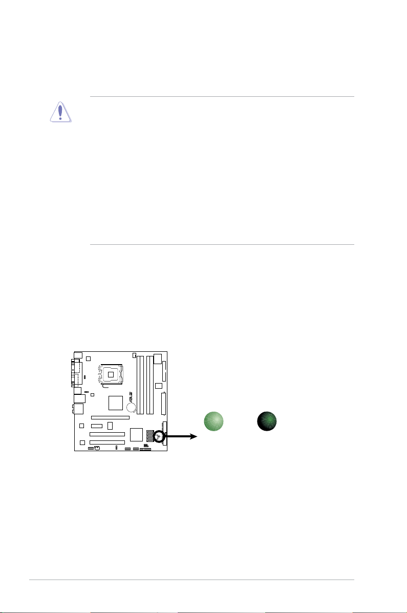
Onboard LED
The motherboard comes with a standby power LED that lights up to indicate
that the system is ON, in sleep mode, or in soft-off mode. This is a reminder
that you should shut down the system and unplug the power cable before
removing or plugging in any motherboard component. The illustration below
shows the location of the onboard LED.
1.4 Before you proceed
Take note of the following precautions before you install motherboard components
or change any motherboard settings.
• Unplug the power cord from the wall socket before touching any
component.
• Use a grounded wrist strap or touch a safely grounded object or to a metal
object, such as the power supply case, before handling components to
avoid damaging them due to static electricity
• Hold components by the edges to avoid touching the ICs on them.
• Whenever you uninstall any component, place it on a grounded antistatic
pad or in the bag that came with the component.
• Before you install or remove any component, ensure that the ATX power
supply is switched off or the power cord is detached from the power
supply. Failure to do so may cause severe damage to the motherboard,
peripherals, and/or components.
P5GC-VM PRO
R
P5GC-VM PRO Onboard LED
SB_PWR
ON
Standby
Power
OFF
Powered
Off
ASUS P5GC-VM PRO 1-7
1.5 Motherboard overview
Before you install the motherboard, study the conguration of your chassis to
ensure that the motherboard ts into it.
Make sure to unplug the power cord before installing or removing the
motherboard. Failure to do so can cause you physical injury and damage
motherboard components.
Do not overtighten the screws! Doing so can damage the motherboard.
1.5.1 Placement direction
When installing the motherboard, make sure that you place it into the chassis in
the correct orientation. The edge with external ports goes to the rear part of the
chassis as indicated in the image below.
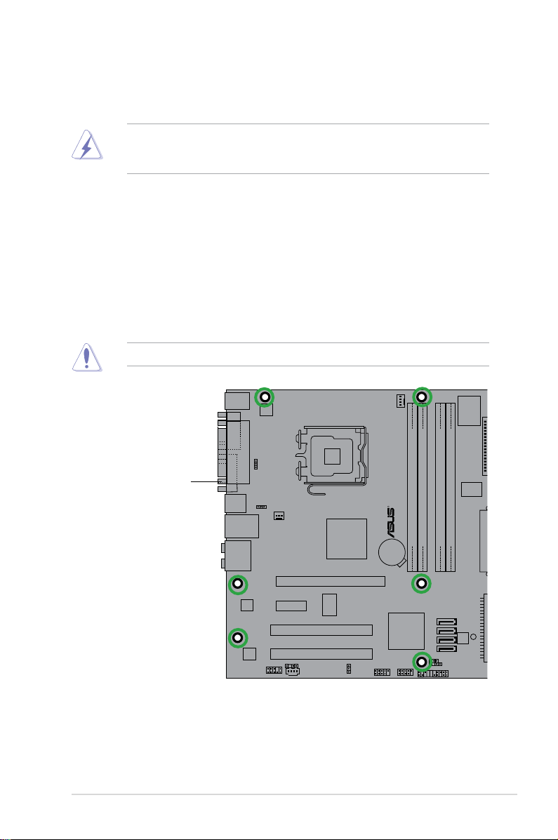
1.5.2 Screw holes
Place six (6) screws into the holes indicated by circles to secure the motherboard
to the chassis.
P5GC-VM PRO
R
Place this side towards
the rear of the chassis
1-8 Chapter 1: Product introduction
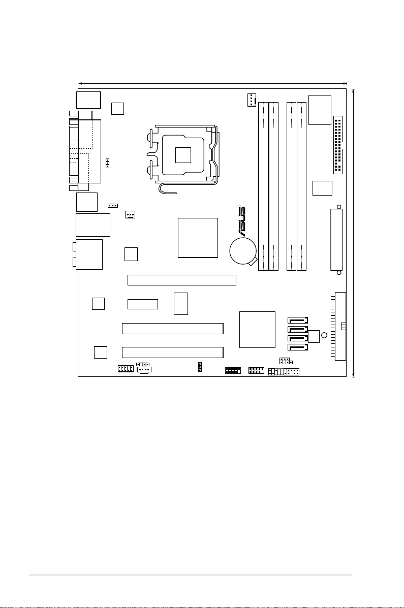
1.5.3 Motherboard layout
22.7cm (8.95in)
24.4cm (9.6in
)
DDR2 DIMM_A1 (64 bit,240-pin module)
DDR2 DIMM_A2 (64 bit,240-pin module)
DDR2 DIMM_B1 (64 bit,240-pin module)
DDR2 DIMM_B2 (64 bit,240-pin module)
P5GC-VM PRO
LAN1_USB12
AUDIO
LGA775
Super I/O
Intel ICH7
PARALLEL
POR
T
VGA COM1
PS/2KBMS
T: Mouse
B: Keyboard
USB34
R
FLOPPY
EA
TXPWR
CPU_FAN
SPDIF_OUT
CD
AAFP
SATA4
SATA3
SATA2
SATA1
PRI_IDE
8Mb
BIOS
CLRTC
CHASSIS
PANEL
CR2032 3V
Lithium Cell
CMOS Power
Intel 945GC
PCI1
PCI2
PCIEX16
PCIEX1_1
USB78USB56
CHA_FAN
ALC883
RTL
8111C
RTM876-660
PS2_USBPW
KBPWR
USBPW1-4
ATX12V
SB_PWR
ICS
9P946AFLF
ASM
4131
ASUS P5GC-VM PRO 1-9
1.6.1 Installling the CPU
To install a CPU:
1. Locate the CPU socket on the motherboard.
1.6 Central Processing Unit (CPU)
The motherboard comes with a surface mount LGA775 socket designed for
the Core™2 Duo EE / Core™2 Duo / Pentium® D / Pentium® 4 and Celeron
®
D
processors.
•
Your boxed Intel® Core™2 EE / Core™2 Duo / Pentium® D / Pentium® 4
or Celeron® D LGA775 processor package should come with installation
instructions for the CPU, fan and heatsink assembly. If the instructions in
this section do not match the CPU documentation, follow the latter.
• Upon purchase of the motherboard, make sure that the PnP cap is on the
socket and the socket pins are not bent. Contact your retailer immediately
if the PnP cap is missing, or if you see any damage to the PnP cap/socket
pins/motherboard components. ASUS will shoulder the cost of repair only if
the damage is shipment/transit-related.
• Keep the cap after installing the motherboard. ASUS will process Return
Merchandise Authorization (RMA) requests only if the motherboard comes
with the cap on the LGA775 socket.
•
The product warranty does not cover damage to the socket pins resulting
from incorrect CPU installation/removal, or misplacement/loss/incorrect
removal of the PnP cap.
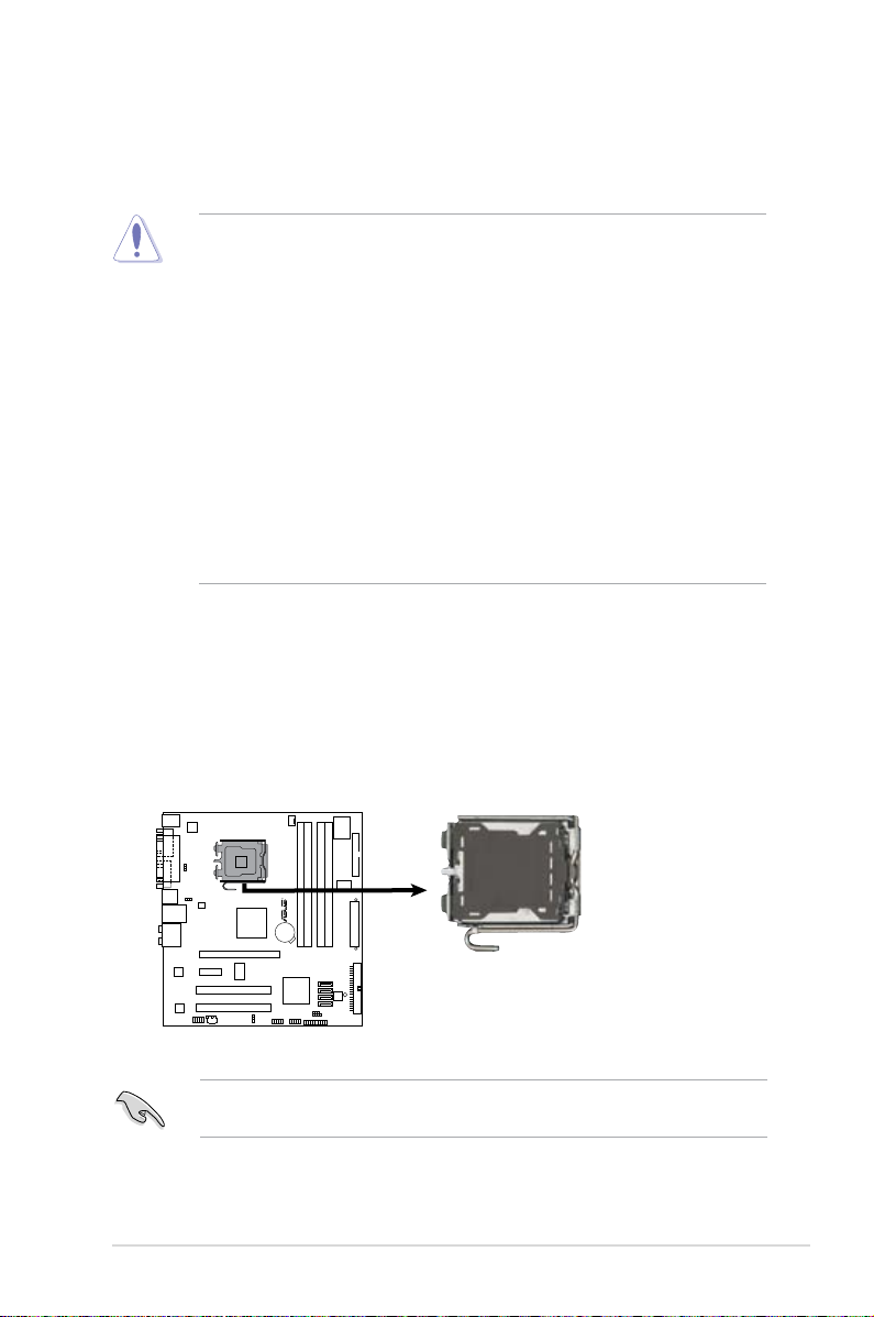
Before installing the CPU, make sure that the socket box is facing towards you
and the load lever is on your left.
P5GC-VM PRO
CPU Socket 775
P5GC-VM PRO
R
1-10 Chapter 1: Product introduction
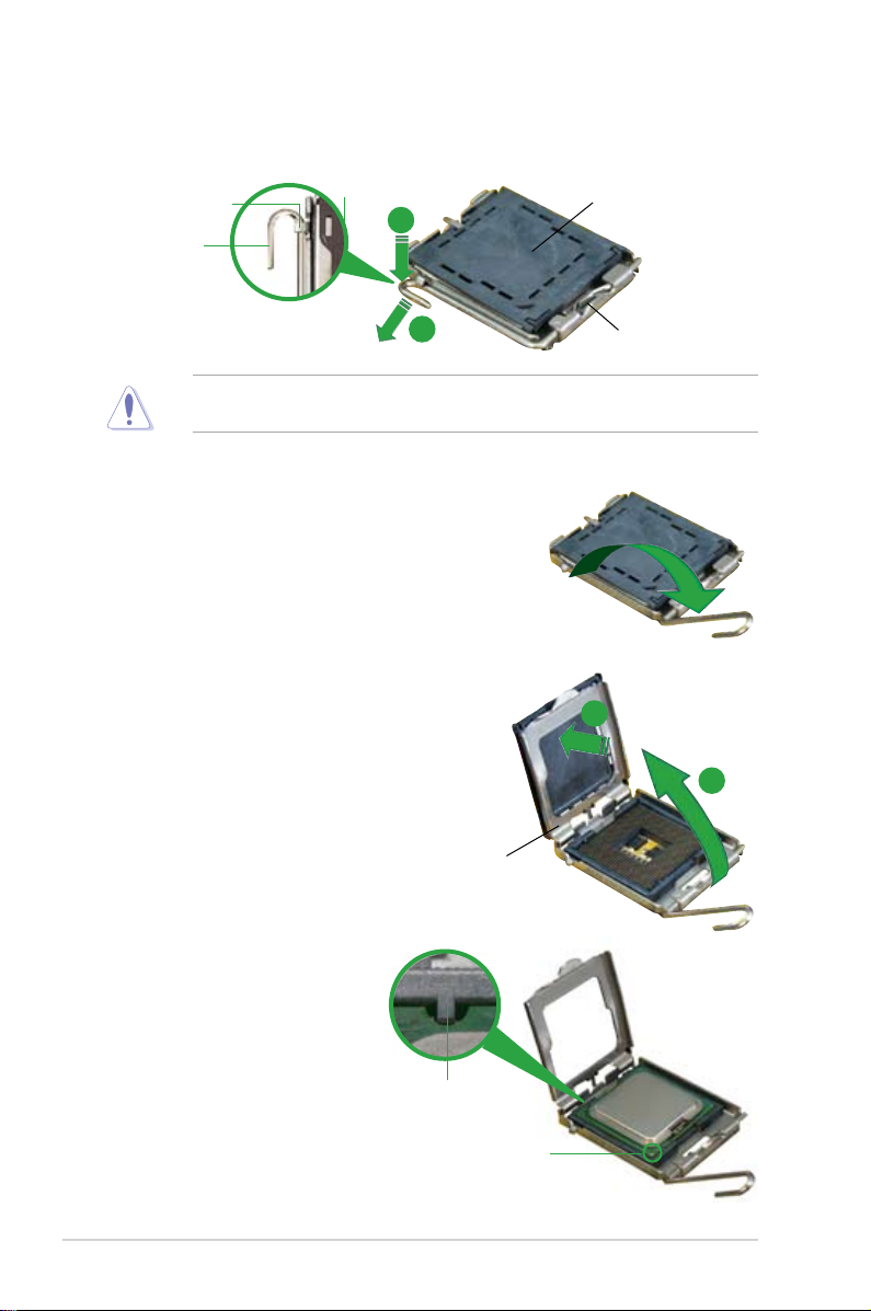
3. Lift the load lever in the direction of
the arrow to a 135º angle.
4. Lift the load plate with your thumb
and forenger to a 100º angle (A),
then push the PnP cap from the load
plate window to remove (B).
To prevent damage to the socket pins, do not remove the PnP cap unless you
are installing a CPU.
5. Position the CPU over
the socket, making sure
that the gold triangle is
on the bottom-left corner
of the socket. The socket
alignment key should t into
the CPU notch.
2. Press the load lever with your thumb (A) and move it to the left (B) until it is
released from the retention tab.
Retention tab
Load lever
This side of the cam box
should face you.
PnP Cap
A
B
Load plate
A
B
Alignment key
Gold triangle mark
ASUS P5GC-VM PRO 1-11
The CPU ts in only one correct orientation. DO NOT force the CPU into the
socket to prevent bending the connectors on the socket and damaging the CPU!
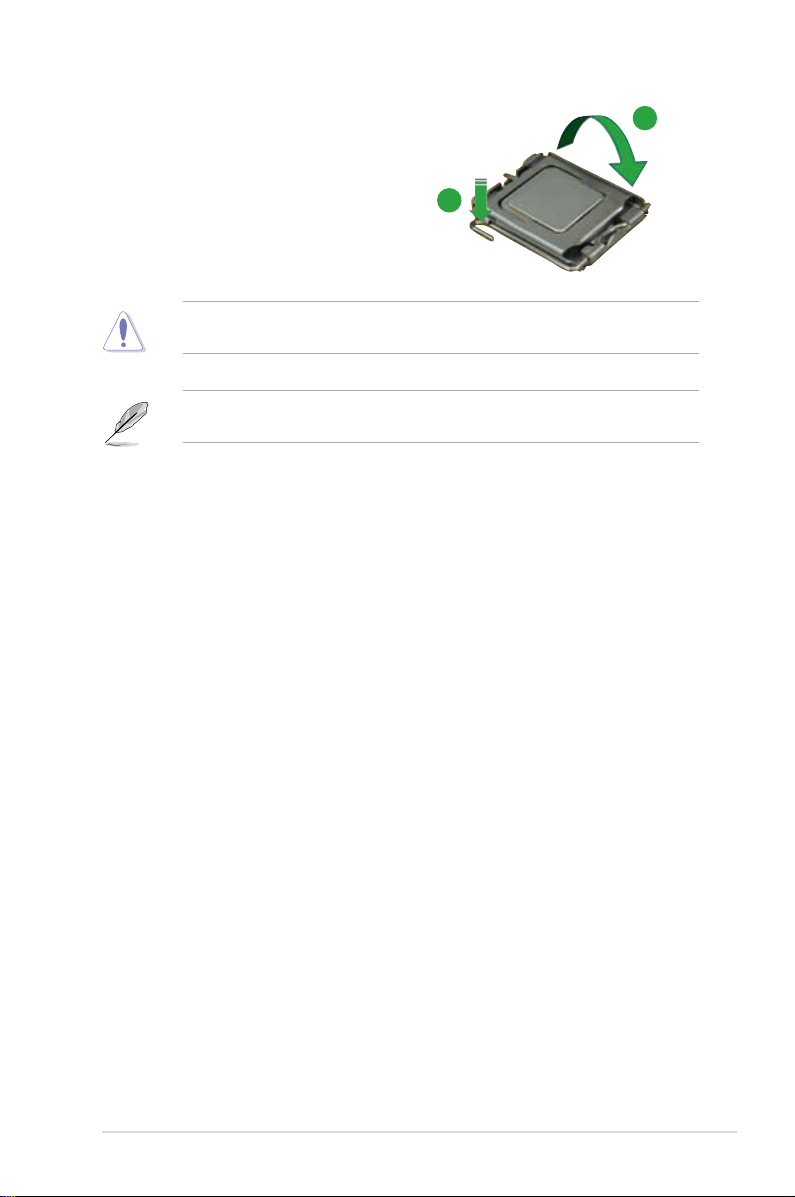
6. Close the load plate (A), then push
the load lever (B) until it snaps into
the retention tab.
A
B
The motherboard supports Intel® LGA775 processors with the Enhanced Intel
SpeedStep® Technology (EIST), and Hyper-Threading Technology.
1-12 Chapter 1: Product introduction
1.6.2 Installling the CPU heatsink and fan
The Intel® Core™2 EE / Core™2 Duo / Pentium® D / Pentium® 4 and Celeron
®
D processors require a specially designed heatsink and fan assembly to ensure
optimum thermal condition and performance.
• Install the motherboard to the chassis before you install the CPU fan and
heatsink assembly
• When you buy a boxed Intel
®
Core™2 EE / Core™2 Duo / Pentium® D /
Pentium® 4 or Celeron® D LGA775 processor, the package includes the
CPU fan and heatsink assembly. If you buy a CPU separately, make sure
that you use only Intel®-certied multi-directional heatsink and fan.
• Your Intel
®
Core™2 EE / Core™2 Duo / Pentium® D / Pentium® 4 or
Celeron® D LGA775 heatsink and fan assembly comes in a push-pin design
and requires no tool to install.
If you purchased a separate CPU heatsink and fan assembly, make sure that
a Thermal Interface Material is properly applied to the CPU heatsink or CPU
before you install the heatsink and fan assembly.
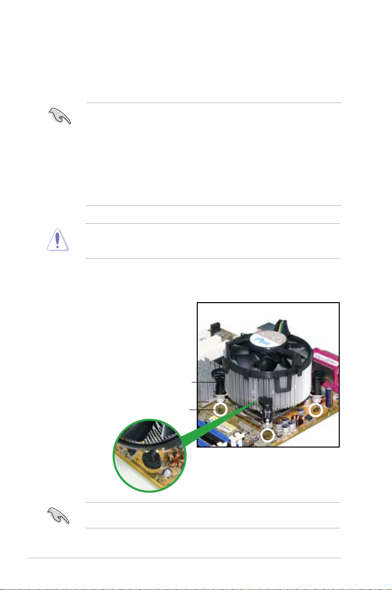
To install the CPU heatsink and fan:
1. Place the heatsink on top of the
installed CPU, making sure that the
four fasteners match the holes on
the motherboard.
Fastener
Motherboard hole
Make sure each fastener is oriented as shown, with the narrow groove directed
outward.
ASUS P5GC-VM PRO 1-13
• Do not forget to connect the CPU fan connector! Hardware monitoring
errors can occur if you fail to plug this connector.
• We recommend you to install the chassis fan for better thermal state.
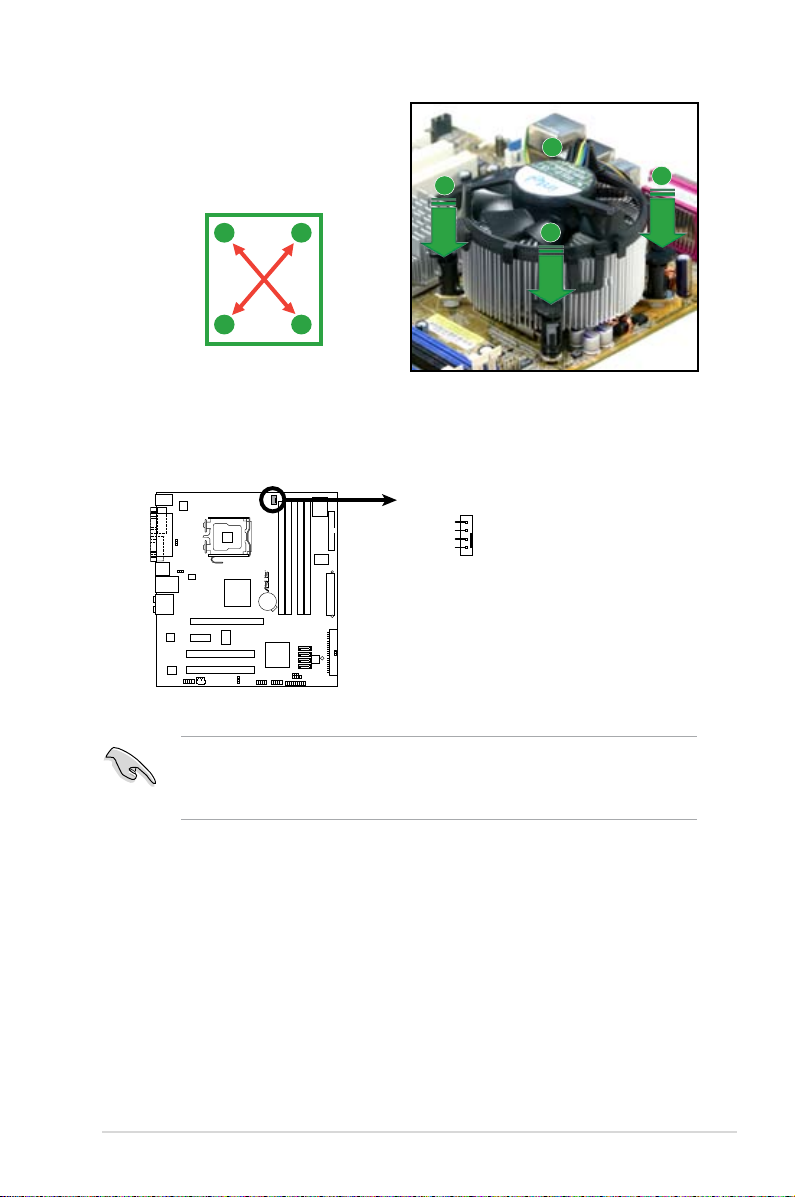
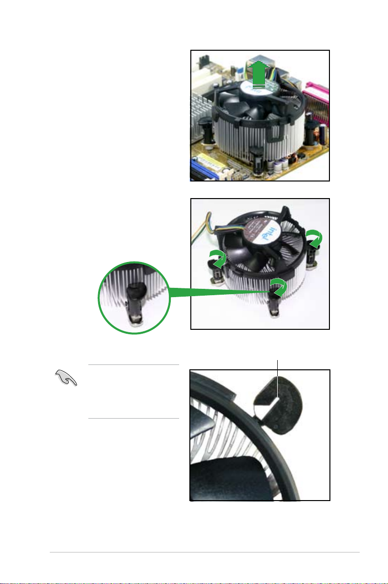
3. When the fan and heatsink assembly is in place, connect the CPU fan cable
to the connector on the motherboard labeled CPU_FAN.
2. Push down two fasteners at a time
in a diagonal sequence to secure
the heatsink and fan assembly in
place.
A
A
B
B
B
B
A
A
P5GC-VM PRO
CPU Fan Connector
P5GC-VM PRO
R
CPU_FAN
GND
+12V
CPU FAN IN
CPU FAN PWM
1-14 Chapter 1: Product introduction
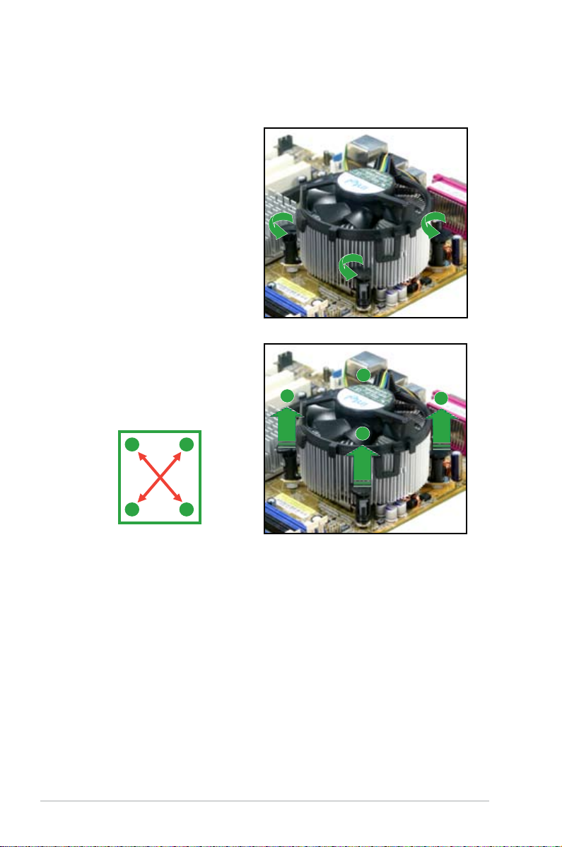
1.6.3 Uninstalling the CPU heatsink and fan
To uninstall the CPU heatsink and fan:
1. Disconnect the CPU fan cable
from the connector on the
motherboard.
2. Rotate each fastener
counterclockwise.
3. Pull up two fasteners at a
time in a diagonal sequence
to disengage the heatsink
and fan assembly from the
motherboard.
A
A
B
B
B
B
A
A
ASUS P5GC-VM PRO 1-15
4. Remove the heatsink and fan
assembly from the motherboard.
5. Rotate each fastener clockwise
to reset the orientation.
The narrow end of the
groove should point outward
after resetting. (The photo
shows the groove shaded
for emphasis.)
Narrow end of the groove
1-16 Chapter 1: Product introduction
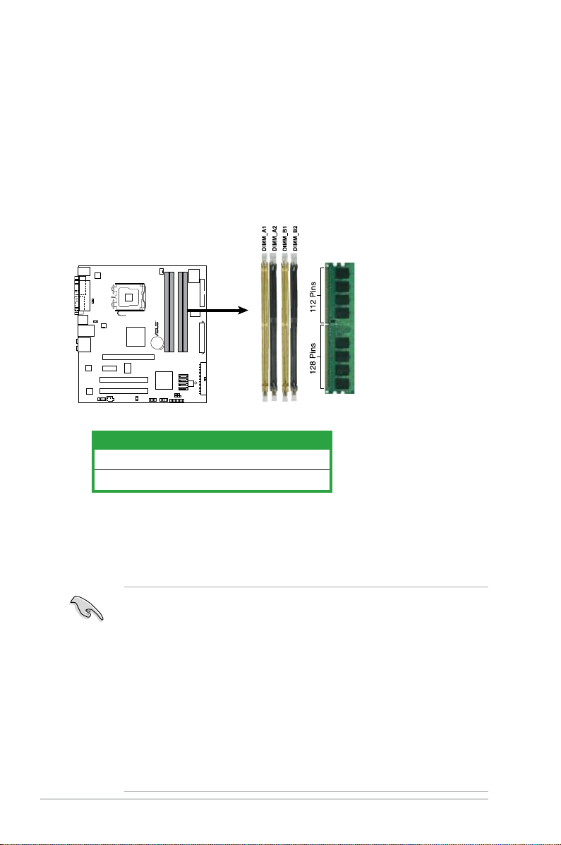
1.7 System memory
1.7.1 Overview
The motherboard comes with four Double Data Rate 2 (DDR2) Dual Inline Memory
Modules (DIMM) sockets.
A DDR2 module has the same physical dimensions as a DDR DIMM but has a
240-pin footprint compared to the 184-pin DDR DIMM. DDR2 DIMMs are notched
differently to prevent installation on a DDR DIMM socket.
The gure illustrates the location of the DDR2 DIMM sockets:
1.7.2 Memory congurations
You may install 256 MB, 512 MB, 1 GB and 2 GB unbuffered non-ECC DDR2
DIMMs into the DIMM sockets.
• For dual-channel conguration, the total size of memory module(s) installed
per channel must be the same (DIMM_A1 = DIMM_B1).
• For single-channel conguration, this motherboard only supports single-
sided memory modules.
• When installing four DDR2 DIMM modules, install the single-sided memory
modules.
• When installing four single-sided DDR2 DIMM modules, the transfer rate
reduces to 533 MHz.
• Always install DIMMs with the same CAS latency. For optimum
compatibility, it is recommended that you obtain memory modules from the
same vendor. Refer to the DDR2 Qualied Vendors List on next page for
details.
Channel Sockets
Channel A DIMM_A1 and DIMM_A2
Channel B DIMM_B1 and DIMM_B2
P5GC-VM PRO
240-pin DDR2 DIMM Sockets
P5GC-VM PRO
R
ASUS P5GC-VM PRO 1-17
1.7.3 DDR2 Qualied Vendors List
The following table lists the memory modules that have been tested and qualied
for use with this motherboard. Visit the ASUS website (www.asus.com) for the
latest DDR2 DIMM modules for this motherboard.
DDR2 533 Qualied Vendors List
DIMM support
Size Vendor Model Brand Side(s) Component A B C
256MB Kingston KVR533D2N4/256 Elpida SS E5116AB-5C-E • • •
256MB Kingston KVR533D2N4/256 Elpida SS E5116AF-5C-E • • •
512MB Kingston KVR533D2N4/512 Inneon SS HYB18T512800AF3733336550 • • •
1G Kingston KVR533D2N4/1G Kingston DS D6408TE7BL-37 • •
1G Kingston KVR533D2N4/1G Kingston DS D6408TLRAGL37U • •
256MB Samsung M378T3253FG0-CD5 Samsung SS K4T56083QF-GCD5 • • •
512MB Samsung M378T6553BG0-CD5 Samsung SS K4T51083QB-GCD5 • • •
512MB Qimonda HYS64T64000GU-3.7-A Qimonda SS HYB18T512800AC37SSS11511 • • •
512MB Qimonda HYS64T64000HU-3.7-A Qimonda SS HYB18T512800AF37FSS29334 • • •
256MB HY HYMP532U64CP6-C4 AB Hynix SS HY5PS121621CFP-C4 • • •
1G HY HYMP512U64CP8-C4 AB Hynix DS HY5PS12821CFP-C4 • •
512MB Micron MT 16HTF6464AG-53EB2 Micron DS D9BOM • •
512MB Corsair VS512MB533D2 Corsair DS MI110052532M8CEC • •
1G Corsair VS1GB533D2 Corsair DS 64M8CFEGQIB0900718 • •
512MB Elpida EBE51UD8ABFA-5C-E Elpida SS E5108AB-5C-E • • •
512MB Kingmax KLBC28F-A8KB4 Kingmax SS KKEA88B4IAK-37 • • •
256MB Kingmax KLBB68F-36EP4 Elpida SS E5116AB-5C-E • • •
512MB Kingmax KLBC28F-A8EB4 Elpida SS E5108AE-5C-E • • •
512MB ADATA M2OAD2G3H3166I1B52 ADATA SS AD29608A8A-37DG20719 • • •
256MB AENEON AET560UD00-370A98Z AENEON SS AET94F370AWVV34635G0520 • • •
512MB AENEON AET660UD00-370A98Z AENEON SS AET93F370A 3VV36328G 0522 • • •
512MB AENEON AET660UD00-370B97X AENEON SS AET93R370B 0640 • • •
1G AENEON AET760UD00-370A98S AENEON DS AET92F370A 0606 • •
1G AENEON AET760UD00-370B97X AENEON DS AET93R370B 0640 • •
1G AENEON AET760UD00-370B97S AENEON DS AET92R370B 0644 • •
2G AENEON AET860UD00-370A08X AENEON DS AET03F370AFVV26176G 0542 • •
512MB REMAXEL RML1040EG38D6F-533 Elpida SS E5108AG-5C-E • • •
256MB TAKEMS TMS25B264B161-534KQ takeMS SS MS18T51216-3.70711 • • •
512MB TAKEMS TMS51B264C081-534QI takeMS SS MS18T51280-3.7 • • •
512MB TAKEMS TMS51B264C081-534AP takeMS SS MS18T51280-3.7P0704D • • •
512MB TAKEMS TMS51B264C081-534AE takeMS SS MS18T51280-3.7EA07100 • • •
1G TAKEMS TMS1GB264C081-534AE takeMS DS MS18T51280-3.7EA0651D • •
1G TAKEMS TMS1GB264C081-534QI takeMS DS MS18T51280-3.7 • •
1G TAKEMS TMS1GB264C081-534AP takeMS DS MS18T51280-3.7P0645D • •
512MB VERITECH GTP512HLTM46DG VERITECH SS VTD264M8PC6G01A164129621 • • •
1G VERITECH GTP01GHLTM56DG VERITECH DS VTD264M8PC6G01A164129621 • •
 Loading...