


ASUS P4SX8-MX User Manual

P4S8X-MX
Motherboard

E1997E1997
E1997
E1997E1997
First Edition V1First Edition V1
First Edition V1
First Edition V1First Edition V1
April 2005April 2005
April 2005
April 2005April 2005
Copyright © 2005 ASUSTeK COMPUTER INC. All Rights Reserved.Copyright © 2005 ASUSTeK COMPUTER INC. All Rights Reserved.
Copyright © 2005 ASUSTeK COMPUTER INC. All Rights Reserved.
Copyright © 2005 ASUSTeK COMPUTER INC. All Rights Reserved.Copyright © 2005 ASUSTeK COMPUTER INC. All Rights Reserved.
No part of this manual, including the products and software described in it, may be reproduced,
transmitted, transcribed, stored in a retrieval system, or translated into any language in any form
or by any means, except documentation kept by the purchaser for backup purposes, without the
express written permission of ASUSTeK COMPUTER INC. (“ASUS”).
Product warranty or service will not be extended if: (1) the product is repaired, modified or
altered, unless such repair, modification of alteration is authorized in writing by ASUS; or (2) the
serial number of the product is defaced or missing.
ASUS PROVIDES THIS MANUAL “AS IS” WITHOUT WARRANTY OF ANY KIND, EITHER EXPRESS OR
IMPLIED, INCLUDING BUT NOT LIMITED TO THE IMPLIED WARRANTIES OR CONDITIONS OF
MERCHANTABILITY OR FITNESS FOR A PARTICULAR PURPOSE. IN NO EVENT SHALL ASUS, ITS
DIRECTORS, OFFICERS, EMPLOYEES OR AGENTS BE LIABLE FOR ANY INDIRECT, SPECIAL,
INCIDENTAL, OR CONSEQUENTIAL DAMAGES (INCLUDING DAMAGES FOR LOSS OF PROFITS, LOSS
OF BUSINESS, LOSS OF USE OR DATA, INTERRUPTION OF BUSINESS AND THE LIKE), EVEN IF ASUS
HAS BEEN ADVISED OF THE POSSIBILITY OF SUCH DAMAGES ARISING FROM ANY DEFECT OR
ERROR IN THIS MANUAL OR PRODUCT.
SPECIFICATIONS AND INFORMATION CONTAINED IN THIS MANUAL ARE FURNISHED FOR
INFORMATIONAL USE ONLY, AND ARE SUBJECT TO CHANGE AT ANY TIME WITHOUT NOTICE, AND
SHOULD NOT BE CONSTRUED AS A COMMITMENT BY ASUS. ASUS ASSUMES NO RESPONSIBILITY
OR LIABILITY FOR ANY ERRORS OR INACCURACIES THAT MAY APPEAR IN THIS MANUAL,
INCLUDING THE PRODUCTS AND SOFTWARE DESCRIBED IN IT.
Products and corporate names appearing in this manual may or may not be registered
trademarks or copyrights of their respective companies, and are used only for identification or
explanation and to the owners’ benefit, without intent to infringe.
iiii
ii
iiii

Contents
Notices ................................................................................................ vi
Safety information ............................................................................. vii
P4S8X-MX specifications summary ................................................... viii
Chapter 1: Product introductionChapter 1: Product introduction
Chapter 1: Product introduction
Chapter 1: Product introductionChapter 1: Product introduction
1.1 Welcome! .............................................................................. 1-2
1.2 Package contents ................................................................. 1-2
1.3 Special features .................................................................... 1-2
1.4 Before you proceed .............................................................. 1-5
1.5 Motherboard overview .......................................................... 1-6
1.5.1 Motherboard layout ................................................ 1-6
1.5.2 Placement direction ................................................ 1-7
1.5.3 Screw holes ............................................................ 1-7
1.6 Central Processing Unit (CPU) .............................................. 1-8
1.6.1 Overview ................................................................. 1-8
1.6.2 Installing the CPU.................................................... 1-8
1.6.3 Installing the heatsink and fan .............................. 1-11
1.7 System memory ................................................................. 1-14
1.7.1 Overview ............................................................... 1-14
1.7.2 Memory configurations ......................................... 1-14
1.7.3 Installing a DIMM ................................................... 1-16
1.7.4 Removing a DIMM ................................................. 1-16
1.8 Expansion slots ................................................................... 1-17
1.8.1 Installing an expansion card .................................. 1-17
1.8.2 Configuring an expansion card.............................. 1-17
1.8.3 PCI slots ................................................................ 1-19
1.8.4 AGP slot ................................................................ 1-19
1.9 Jumpers .............................................................................. 1-20
1.10 Connectors ......................................................................... 1-23
1.10.1 Rear panel connectors .......................................... 1-23
1.10.2 Internal connectors............................................... 1-25
iiiiii
iii
iiiiii

Contents
Chapter 2: BIOS setupChapter 2: BIOS setup
Chapter 2: BIOS setup
Chapter 2: BIOS setupChapter 2: BIOS setup
2.1 Managing and updating your BIOS ........................................ 2-2
2.1.1 Creating a bootable floppy disk .............................. 2-2
2.1.2 ASUS EZ Flash utility .............................................. 2-3
2.1.3 AFUDOS utility ........................................................ 2-4
2.1.4 ASUS CrashFree BIOS 2 utility ................................ 2-6
2.1.5 ASUS Update utility ................................................ 2-8
2.2 BIOS setup program ........................................................... 2-11
2.2.1 BIOS menu screen ................................................. 2-12
2.2.2 Menu bar ............................................................... 2-12
2.2.3 Navigation keys .................................................... 2-12
2.2.4 Menu items ........................................................... 2-13
2.2.5 Sub-menu items ................................................... 2-13
2.2.6 Configuration fields .............................................. 2-13
2.2.7 Pop-up window ..................................................... 2-13
2.2.8 Scroll bar .............................................................. 2-13
2.2.9 General help .......................................................... 2-13
2.3 Main menu .......................................................................... 2-14
2.3.1 System Time ......................................................... 2-14
2.3.2 System Date ......................................................... 2-14
2.3.3 Legacy Diskette A ................................................ 2-14
2.3.4 Primary and Secondary IDE Master/Slave ............. 2-15
2.3.5 OnChip SATA Controller ....................................... 2-16
2.3.6 System Information .............................................. 2-16
2.4 Advanced menu .................................................................. 2-17
2.4.1 JumperFree Configuration .................................... 2-18
2.4.2 CPU Configuration ................................................. 2-20
2.4.3 Chipset ................................................................. 2-21
2.4.4 Onboard Devices Configuration ............................ 2-23
2.4.5 PCI PnP ................................................................. 2-24
iviv
iv
iviv
2.4.6 USB Configuration................................................. 2-27

Contents
2.5 Power menu ........................................................................ 2-28
2.5.1 Suspend Mode ...................................................... 2-28
2.5.2 ACPI 2.0 Support .................................................. 2-28
2.5.3 ACPI APIC Support ................................................ 2-28
2.5.4 APM Configuration ................................................ 2-29
2.5.5 Hardware Monitor ................................................. 2-31
2.6 Boot menu .......................................................................... 2-32
2.6.1 Boot Device Priority .............................................. 2-32
2.6.2 Removable Drives ................................................. 2-33
2.6.3 Boot Settings Configuration ................................. 2-33
2.6.4 Security ................................................................ 2-35
2.7 Exit menu ........................................................................... 2-37
Chapter 3: Software supportChapter 3: Software support
Chapter 3: Software support
Chapter 3: Software supportChapter 3: Software support
3.1 Installing an operating system ............................................. 3-2
3.2 Support CD information ........................................................ 3-2
3.2.1 Running the support CD ......................................... 3-2
3.2.2 Drivers menu .......................................................... 3-3
3.2.3 Utilities menu .......................................................... 3-4
3.2.4 ASUS Contact information ...................................... 3-6
3.2.5 Other information ................................................... 3-6
3.3 RAID configurations .............................................................. 3-8
3.3.1 Installing hard disks ................................................ 3-8
3.3.2 SIS RAID configurations .......................................... 3-9
3.4 Creating a RAID driver disk ................................................. 3-18
vv
v
vv

Notices
Federal Communications Commission StatementFederal Communications Commission Statement
Federal Communications Commission Statement
Federal Communications Commission StatementFederal Communications Commission Statement
This device complies with Part 15 of the FCC Rules. Operation is subject to
the following two conditions:
•
This device may not cause harmful interference, and
•
This device must accept any interference received including interference
that may cause undesired operation.
This equipment has been tested and found to comply with the limits for a
Class B digital device, pursuant to Part 15 of the FCC Rules. These limits are
designed to provide reasonable protection against harmful interference in a
residential installation. This equipment generates, uses and can radiate radio
frequency energy and, if not installed and used in accordance with
manufacturer’s instructions, may cause harmful interference to radio
communications. However, there is no guarantee that interference will not
occur in a particular installation. If this equipment does cause harmful
interference to radio or television reception, which can be determined by
turning the equipment off and on, the user is encouraged to try to correct
the interference by one or more of the following measures:
•
Reorient or relocate the receiving antenna.
•
Increase the separation between the equipment and receiver.
•
Connect the equipment to an outlet on a circuit different from that to
which the receiver is connected.
•
Consult the dealer or an experienced radio/TV technician for help.
The use of shielded cables for connection of the monitor to the graphics
card is required to assure compliance with FCC regulations. Changes or
modifications to this unit not expressly approved by the party
responsible for compliance could void the user’s authority to operate
this equipment.
Canadian Department of Communications StatementCanadian Department of Communications Statement
Canadian Department of Communications Statement
Canadian Department of Communications StatementCanadian Department of Communications Statement
This digital apparatus does not exceed the Class B limits for radio noise
emissions from digital apparatus set out in the Radio Interference
Regulations of the Canadian Department of Communications.
This class B digital apparatus complies with CanadianThis class B digital apparatus complies with Canadian
This class B digital apparatus complies with Canadian
This class B digital apparatus complies with CanadianThis class B digital apparatus complies with Canadian
ICES-003.ICES-003.
ICES-003.
ICES-003.ICES-003.
vivi
vi
vivi

Safety information
Electrical safetyElectrical safety
Electrical safety
Electrical safetyElectrical safety
•
To prevent electrical shock hazard, disconnect the power cable from the
electrical outlet before relocating the system.
•
When adding or removing devices to or from the system, ensure that the
power cables for the devices are unplugged before the signal cables are
connected. If possible, disconnect all power cables from the existing
system before you add a device.
•
Before connecting or removing signal cables from the motherboard,
ensure that all power cables are unplugged.
•
Seek professional assistance before using an adapter or extension cord.
These devices could interrupt the grounding circuit.
•
Make sure that your power supply is set to the correct voltage in your
area. If you are not sure about the voltage of the electrical outlet you are
using, contact your local power company.
•
If the power supply is broken, do not try to fix it by yourself. Contact a
qualified service technician or your retailer.
Operation safetyOperation safety
Operation safety
Operation safetyOperation safety
•
Before installing the motherboard and adding devices on it, carefully read
all the manuals that came with the package.
•
Before using the product, make sure all cables are correctly connected
and the power cables are not damaged. If you detect any damage,
contact your dealer immediately.
•
To avoid short circuits, keep paper clips, screws, and staples away from
connectors, slots, sockets and circuitry.
•
Avoid dust, humidity, and temperature extremes. Do not place the
product in any area where it may become wet.
•
Place the product on a stable surface.
•
If you encounter technical problems with the product, contact a qualified
service technician or your retailer.
viivii
vii
viivii

P4S8X-MX specifications summary
CPUCPU
CPU
CPUCPU
ChipsetChipset
Chipset
ChipsetChipset
Front Side BusFront Side Bus
Front Side Bus
Front Side BusFront Side Bus
MemoryMemory
Memory
MemoryMemory
Expansion slotsExpansion slots
Expansion slots
Expansion slotsExpansion slots
GraphicsGraphics
Graphics
GraphicsGraphics
StorageStorage
Storage
StorageStorage
AudioAudio
Audio
AudioAudio
Socket 478 for Intel
®
Pentium® 4 / Celeron processors
Supports Intel® Hyper-Threading Technology
Northbridge: SiS 661GX
Southbridge: SiS 964
800*/533 MHz
2 x 184-pin DIMM sockets support up to 2 GB of
unbufferred non-ECC 400**/333 MHz DDR SDRAM
memory modules
1 x AGP 8X slot (1.5 V only)
3 x PCI slots
SiS Real 256E Graphics
SiS 964 Southbridge supports:
- 4 x Ultra DMA 133/100/66/33 hard disk drives
- 2 x Serial ATA drives with RAID 0, RAID 1, and
JBOD configuration
®
Realtek
ALC655 6-channel CODEC
Coaxial S/PDIF out port
LANLAN
LAN
LANLAN
OverclockingOverclocking
Overclocking
OverclockingOverclocking
USBUSB
USB
USBUSB
Special featuresSpecial features
Special features
Special featuresSpecial features
* The motherboard runs at FSB800 when in overclock mode.
** 1. When using an FSB800 CPU with 400 MHz DDR memory, the
motherboard runs at 333 MHz by default.
2. When using an FSB533 CPU with 400 MHz DDR memory, the
motherboard runs at 400 MHz.
Realtek® RTL8201CL 10/100 Mbps LAN PHY
Stepless Frequency Selection (SFS) from 100 MHz up
to 200 MHz at 1 MHz increment
AGP/PCI Asynchronous Mode with FSB
ASUS C.P.R. (CPU Parameter Recall)
Supports up to 8 USB 2.0 ports
ASUS CrashFree BIOS 2
ASUS EZ Flash
ASUS MyLogo2™
(continued on the next page)
viiiviii
viii
viiiviii

P4S8X-MX specifications summary
BIOS featuresBIOS features
BIOS features
BIOS featuresBIOS features
Rear panelRear panel
Rear panel
Rear panelRear panel
InternalInternal
Internal
InternalInternal
connectorsconnectors
connectors
connectorsconnectors
4 Mb Flash ROM, AMI BIOS, Green, PnP, DMI2.0,
SM BIOS 2.3, WfM2.0, ACPI 2.0
1 x Parallel port
1 x LAN (RJ-45) port
4 x USB 2.0 ports
1 x VGA port
1 x Serial port (COM)
1 x PS/2 keyboard port
1 x PS/2 mouse port
6-channel audio ports
1 x Floppy disk drive connector
1 x Primary IDE connector
1 x Secondary IDE connector
2 x Serial ATA connectors
1 x CPU fan connector
1 x Chassis fan connector
2 x USB 2.0 connectors for four additional USB 2.0 ports
1 x Optical drive audio connector
1 x AUX connector
20-pin ATX power connector
4-pin x ATX 12V power connector
1 x GAME/MIDI connector
1 x S/PDIF Out connector
1 x Front panel audio connector
System panel connector
PowerPower
Power
PowerPower
RequirementRequirement
Requirement
RequirementRequirement
Form FactorForm Factor
Form Factor
Form FactorForm Factor
Support CDSupport CD
Support CD
Support CDSupport CD
contentscontents
contents
contentscontents
ATX power supply (with 20-pin and 4-pin 12 V plugs)
ATX 12 V 2.0 compliant
ATX form factor: 9.6 in x 9.6 in (24.5 cm x 24.5 cm)
Device drivers
ASUS PC Probe
ASUS Live Update utility
ASUS Screensaver
Adobe Acrobat Reader
Anti-virus software (OEM version)
*Specifications are subject to change without notice.
ixix
ix
ixix

xx
x
xx

This chapter describes the motherboard
features and the new technologies
it supports.
introduction
Product
1

1.1 Welcome!
®®
®
Thank you for buying an ASUSThank you for buying an ASUS
Thank you for buying an ASUS
Thank you for buying an ASUSThank you for buying an ASUS
®®
P4S8X-MX motherboard! P4S8X-MX motherboard!
P4S8X-MX motherboard!
P4S8X-MX motherboard! P4S8X-MX motherboard!
The motherboard delivers a host of new features and latest technologies,
making it another standout in the long line of ASUS quality motherboards!
Before you start installing the motherboard, and hardware devices on it,
check the items in your package with the list below.
1.2 Package contents
Check your motherboard package for the following items.
MotherboardMotherboard
Motherboard ASUS P4S8X-MX motherboard
MotherboardMotherboard
CablesCables
Cables 1 x Serial ATA signal cable
CablesCables
1 x Serial ATA power cable
1 x Ultra DMA 133/100/66 cable
Floppy disk drive cable
AccessoriesAccessories
Accessories I/O shield
AccessoriesAccessories
Application CDsApplication CDs
Application CDs ASUS motherboard support CD
Application CDsApplication CDs
DocumentationDocumentation
Documentation User guide
DocumentationDocumentation
If any of the above items is damaged or missing, contact your retailer.
1.3 Special features
SiS661GX/964 chipsetSiS661GX/964 chipset
SiS661GX/964 chipset
SiS661GX/964 chipsetSiS661GX/964 chipset
Embedded in this motherboard is the SiS661GX/964 chipset that
integrates various SiS-developed technologies to ensure an efficient and
reliable computing performance.
The SiS661GX chipset provides a high performance host interface for the
®
Intel
Pentium® 4 processor, and supports AGP 8X and DDR400. The
SiS661GX features the SiS HyperStreaming™ Engine that smartly manages
data streams between peripherals, core logic chipsets, front side bus,
memory and graphic interfaces. This technology dramatically optimizes and
improves the entire computer system performance.
Providing I/O and peripheral support is the SiS964 Southbridge, which
integrates various I/O functions including dual-channel ATA133 bus master
IDE, USB 2.0/1.1, Ethernet, and audio controllers. The SiS964 provides
1-21-2
1-2
1-21-2
Chapter 1: Product introductionChapter 1: Product introduction
Chapter 1: Product introduction
Chapter 1: Product introductionChapter 1: Product introduction

LPC and AC’97 interfaces, and complies with the Advanced Power
Management (APM) 1.2 specification. The SiS964 interconnects with the
Northbridge at up to 1GB/s using the SiS proprietary MuTIOL
interface.
Real256E integrated graphics Real256E integrated graphics
Real256E integrated graphics
Real256E integrated graphics Real256E integrated graphics
Embedded in the Northbridge is the SiS Real256E integrated graphics with
a 256-bit 3D engine and 2D graphics accelerator with a maximum 64MB
shared display memory. The Real256E integrated graphics engine
incorporates the UltraAGPII™ technology to provide a faster link between
the built-in graphic engine and the northbridge memory controller. This
technology boosts VGA throughput to up to 3.2 GB/s to bring clearer and
sharper images for your multimedia and graphic-intensive applications. The
Real256E integrated graphics achieves a maximum resolution of
2048x1536 at 32 bpp. See page 1-24.
Serial ATA technology Serial ATA technology
Serial ATA technology
Serial ATA technology Serial ATA technology
®
bus
The motherboard supports the Serial ATA technology through the Serial ATA
interfaces and the Intel® ICH6. The SATA specification allows for thinner,
more flexible cables with lower pin count, reduced voltage requirement, and
up to 150 MB/s data transfer rate. See page 1-27 for details.
Integrated 10/100 Mbps LAN controller Integrated 10/100 Mbps LAN controller
Integrated 10/100 Mbps LAN controller
Integrated 10/100 Mbps LAN controller Integrated 10/100 Mbps LAN controller
Onboard is the Realtek® LAN PHY that interconnects with the SiS964
southbridge LAN controller to fully support 10BASE-T/ 100BASE-TX
Ethernet networking. See page 1-23.
6-Channel Audio solution 6-Channel Audio solution
6-Channel Audio solution
6-Channel Audio solution 6-Channel Audio solution
The motherboard uses an onboard audio CODEC that lets you enjoy highquality 6-channel audio without having to buy advanced sound cards. See
page 1-23.
DDR400 Support DDR400 Support
DDR400 Support
DDR400 Support DDR400 Support
The motherboard supports up to 2 GB system memory using DDR400/
333/266 non-ECC DDR DIMMs to deliver up to 3.2 GB/s data transfer rate
for the latest 3D graphics, multimedia, and Internet applications. See page
1-15 for details.
ASUS P4S8X-MXASUS P4S8X-MX
ASUS P4S8X-MX
ASUS P4S8X-MXASUS P4S8X-MX
1-31-3
1-3
1-31-3

USB 2.0 technology USB 2.0 technology
USB 2.0 technology
USB 2.0 technology USB 2.0 technology
The motherboard implements the Universal Serial Bus (USB) 2.0
specification, dramatically increasing the connection speed from the
12 Mbps bandwidth on USB 1.1 to a fast 480 Mbps on USB 2.0. USB 2.0 is
backward compatible with USB 1.1. See pages 1-24 and 1-29 for details.
ASUS CrashFree BIOS 2 ASUS CrashFree BIOS 2
ASUS CrashFree BIOS 2
ASUS CrashFree BIOS 2 ASUS CrashFree BIOS 2
This feature allows you to restore the original BIOS data from the support
CD in case when the BIOS codes and data are corrupted. This protection
eliminates the need to buy a replacement ROM chip. See page 2-6 for
details.
ASUS EZ Flash BIOS ASUS EZ Flash BIOS
ASUS EZ Flash BIOS
ASUS EZ Flash BIOS ASUS EZ Flash BIOS
With the ASUS EZ Flash, you can easily update the system BIOS even
before loading the operating system. No need to use a DOS-based utility or
boot from a floppy disk. See page 2-3 for details.
ASUS MyLogo2™ ASUS MyLogo2™
ASUS MyLogo2™
ASUS MyLogo2™ ASUS MyLogo2™
This new feature present in the motherboard allows you to personalize and
add style to your system with customizable boot logos. See page 2-33 for
details.
C.P.R. (CPU Parameter Recall) C.P.R. (CPU Parameter Recall)
C.P.R. (CPU Parameter Recall)
C.P.R. (CPU Parameter Recall) C.P.R. (CPU Parameter Recall)
The C.P.R. feature of the motherboard BIOS allows automatic re-setting to
the BIOS default settings in case the system hangs due to overclocking.
When the system hangs due to overclocking, C.P.R. eliminates the need to
open the system chassis and clear the RTC data. Simply shut down and
reboot the system, and the BIOS automatically restores the CPU default
setting for each parameter.
1-41-4
1-4
1-41-4
Chapter 1: Product introductionChapter 1: Product introduction
Chapter 1: Product introduction
Chapter 1: Product introductionChapter 1: Product introduction
1.4 Before you proceed
d
Take note of the following precautions before you install motherboard
components or change any motherboard settings.
• Unplug the power cord from the wall socket before touching any
component.
• Use a grounded wrist strap or touch a safely grounded object or a
metal object, such as the power supply case, before handling
components to avoid damaging them due to static electricity
• Hold components by the edges to avoid touching the ICs on them.
• Whenever you uninstall any component, place it on a grounded
antistatic pad or in the bag that came with the component.
Before you install or remove any component, ensureBefore you install or remove any component, ensure
•
Before you install or remove any component, ensure
Before you install or remove any component, ensureBefore you install or remove any component, ensure
that the ATX power supply is switched off or thethat the ATX power supply is switched off or the
that the ATX power supply is switched off or the
that the ATX power supply is switched off or thethat the ATX power supply is switched off or the
power cord is detached from the power supply. power cord is detached from the power supply.
power cord is detached from the power supply. Failure
power cord is detached from the power supply. power cord is detached from the power supply.
to do so may cause severe damage to the motherboard, peripherals,
and/or components.
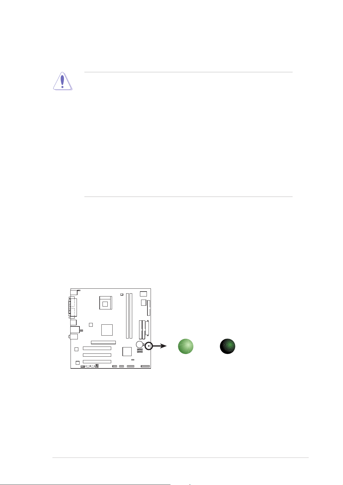
Onboard LEDOnboard LED
Onboard LED
Onboard LEDOnboard LED
The motherboard comes with a standby power LED that lights up to
indicate that the system is ON, in sleep mode, or in soft-off mode.
This is a reminder that you should shut down the system and unplug
the power cable before removing or plugging in any motherboard
component. The illustration below shows the location of the onboard
LED.
P4S8X-MX
SB_PWR
ON
Standby
Power
P4S8X-MX Onboard LED
OFF
Powere
Off
ASUS P4S8X-MXASUS P4S8X-MX
ASUS P4S8X-MX
ASUS P4S8X-MXASUS P4S8X-MX
1-51-5
1-5
1-51-5
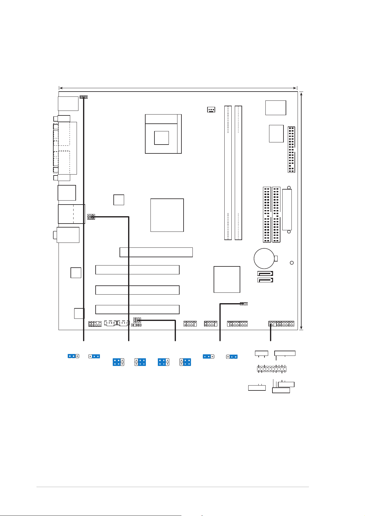
1.5 Motherboard overview
24.5cm (9.6in)
1.5.11.5.1
1.5.1
1.5.11.5.1
PS/2KBMS
T: Mouse
B: Keyboard
COM1
PARALLEL PORT
VGA
USB12
TOP
USB34
RJ-45
Top:Line In
Center:Line Out
Below:Mic In
Motherboard layoutMotherboard layout
Motherboard layout
Motherboard layoutMotherboard layout
KBPWR
Socket 478
USBPW34
USBPW12
ATX12V
SiS
661GX
North Bridge
CPU_FAN1
P4S8X-MX
DDR DIMM1 (64 bit,184-pin module)
Super
I/O
4Mb
BIOS
FLOPPY
PRI_IDE
SEC_IDE
DDR DIMM2 (64 bit,184-pin module)
ATXPWR
24.5cm (9.6in)
RTL8201CL
ALC655
FP_AUDIO
KBPWR
+5V +5VSB
(Default)
PCI1
AGP
SiS
964
Chipset
SATA2
SATA1
CR2032 3V
Lithium Cell
CMOS Power
SB_PWR
PCI2
CLRTC1
PCI3
CDAUX
USBPW34
2312
USBPW12
+5V
(Default)
2321
+5VSB
USBPW56
USBPW78
SPDIF
USBPW56
USBPW78
+5V
(Default)
USB56
2321
+5VSB
USB78 PANEL
CLRTC1
12 23
GAME
NormalClear CMOS
(Default)
PANEL
PLED
IDE_LED
*
Requires an ATX power supply.
PLED+
IDE_LED-
IDE_LED+
PLED-
SPEAKER
+5V
PWR
Ground
PWRSW
Ground
Speaker
Ground
Reset
Ground
RESET
1-61-6
1-6
1-61-6
Chapter 1: Product introductionChapter 1: Product introduction
Chapter 1: Product introduction
Chapter 1: Product introductionChapter 1: Product introduction
1.5.21.5.2
1.5.2
1.5.21.5.2
When installing the motherboard, make sure that you place it into the
chassis in the correct orientation. The edge with external ports goes to the
rear part of the chassis as indicated in the image below.
Placement directionPlacement direction
Placement direction
Placement directionPlacement direction
1.5.31.5.3
1.5.3
1.5.31.5.3
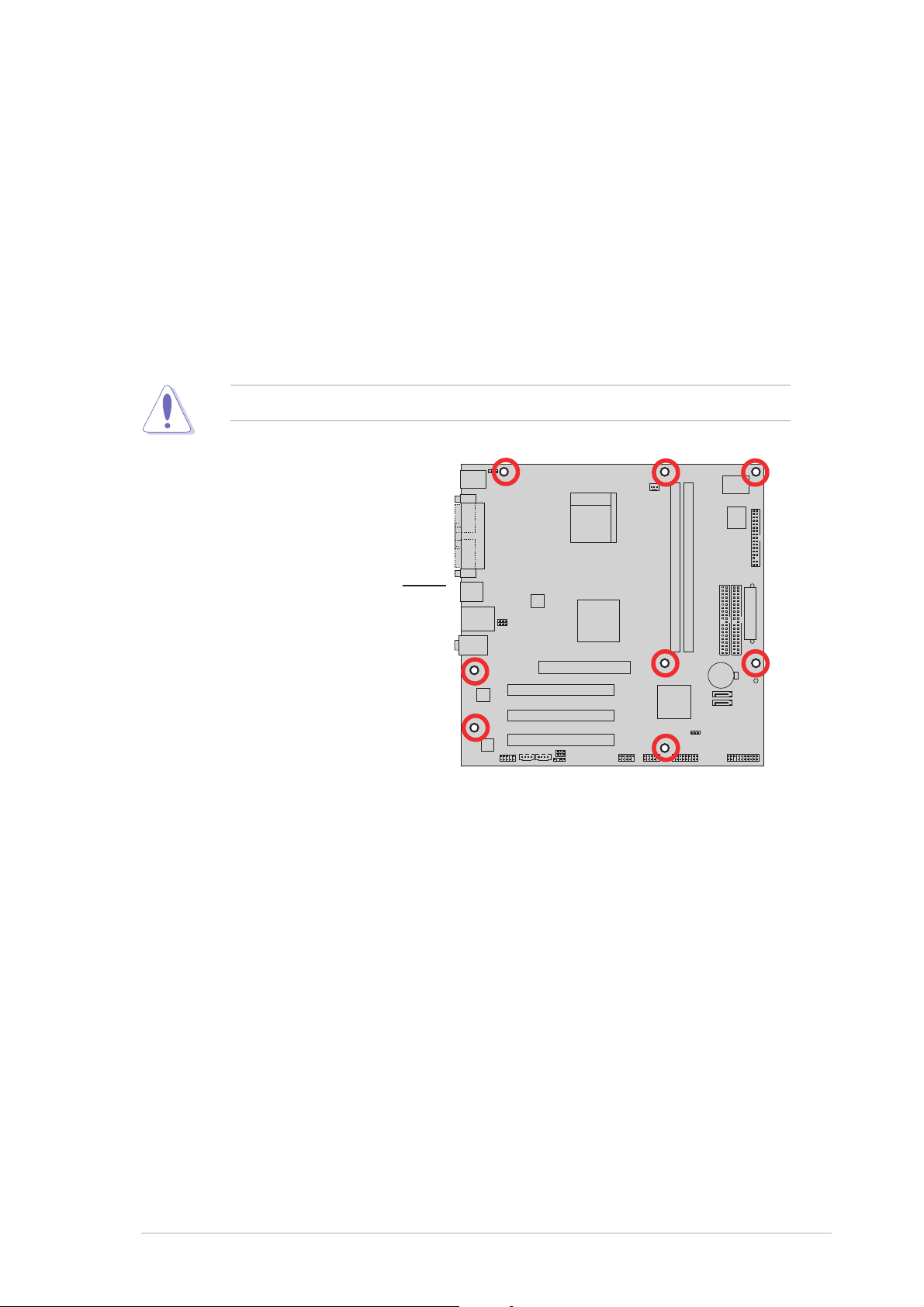
Screw holesScrew holes
Screw holes
Screw holesScrew holes
Place eight (8) screws into the holes indicated by circles to secure the
motherboard to the chassis.
Do not overtighten the screws! Doing so can damage the motherboard.
P4S8X-MX
Place this side towardsPlace this side towards
Place this side towards
Place this side towardsPlace this side towards
the rear of the chassisthe rear of the chassis
the rear of the chassis
the rear of the chassisthe rear of the chassis
ASUS P4S8X-MXASUS P4S8X-MX
ASUS P4S8X-MX
ASUS P4S8X-MXASUS P4S8X-MX
1-71-7
1-7
1-71-7
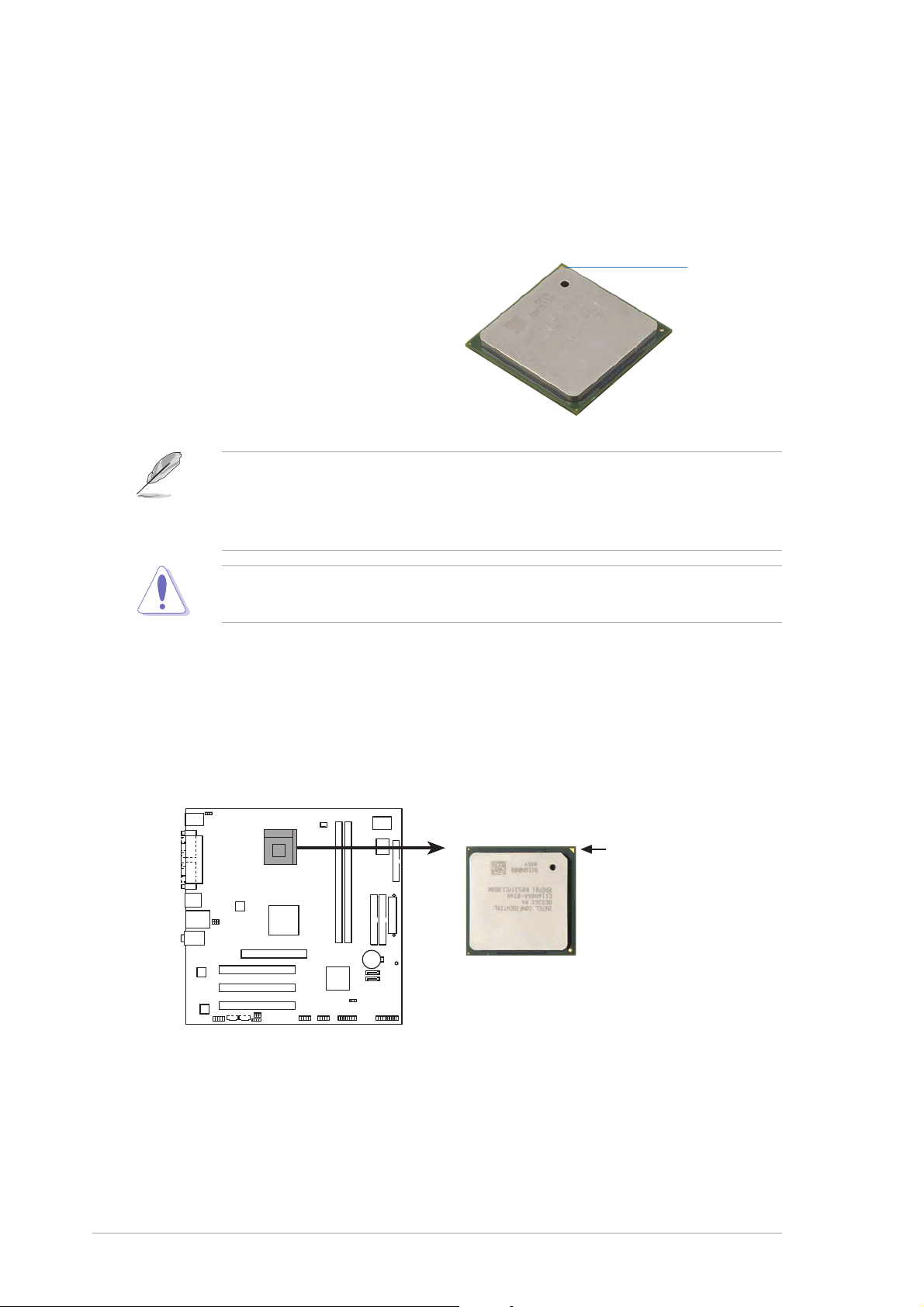
1.6 Central Processing Unit (CPU)
1.6.11.6.1
1.6.1
1.6.11.6.1
The motherboard comes with a surface mount 478-pin Zero Insertion Force
(ZIF) socket designed for the Intel® Pentium® 4 Processor.
Take note of the marked corner (with
gold triangle) on the CPU. This mark
should match a specific corner on the
socket to ensure correct installation.
OverviewOverview
Overview
OverviewOverview
Gold mark
Your boxed Intel® Pentium® 4 processor package should come with
installation instructions for the CPU, heatsink, and the retention
mechanism. If the instructions in this section do not match the CPU
documentation, follow the latter.
Incorrect installation of the CPU into the socket can bend the pins and
severely damage the CPU!
1.6.21.6.2
1.6.2
1.6.21.6.2
Follow these steps to install a CPU.
1. Locate the 478-pin ZIF socket on the motherboard.
Installing the CPUInstalling the CPU
Installing the CPU
Installing the CPUInstalling the CPU
P4S8X-MX
P4S8X-MX CPU Socket 478
Gold Arrow
1-81-8
1-8
1-81-8
Chapter 1: Product introductionChapter 1: Product introduction
Chapter 1: Product introduction
Chapter 1: Product introductionChapter 1: Product introduction
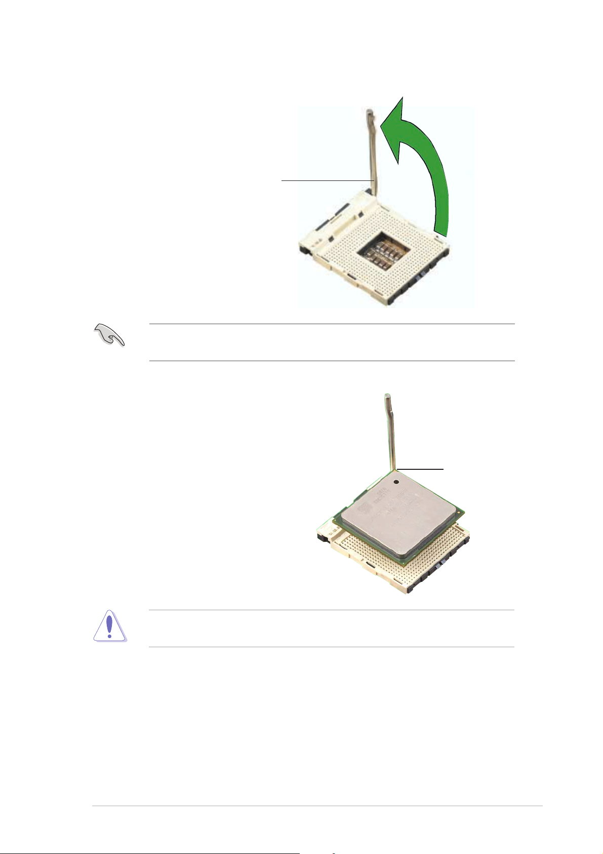
2. Unlock the socket by pressing
the lever sideways, then lift it up
to a 90°-100° angle.
Socket leverSocket lever
Socket lever
Socket leverSocket lever
Make sure that the socket lever is lifted up to 90°-100° angle;
otherwise, the CPU does not fit in completely.
3. Position the CPU above the
socket such that its marked
corner matches the base of the
socket lever.
90°-100°90°-100°
90°-100°
90°-100°90°-100°
angleangle
angle
angleangle
4. Carefully insert the CPU into the
socket until it fits in place.
The CPU fits only in one correct orientation. DO NOT force the CPU into
the socket to prevent bending the pins and damaging the CPU!
Gold markGold mark
Gold mark
Gold markGold mark
ASUS P4S8X-MXASUS P4S8X-MX
ASUS P4S8X-MX
ASUS P4S8X-MXASUS P4S8X-MX
1-91-9
1-9
1-91-9
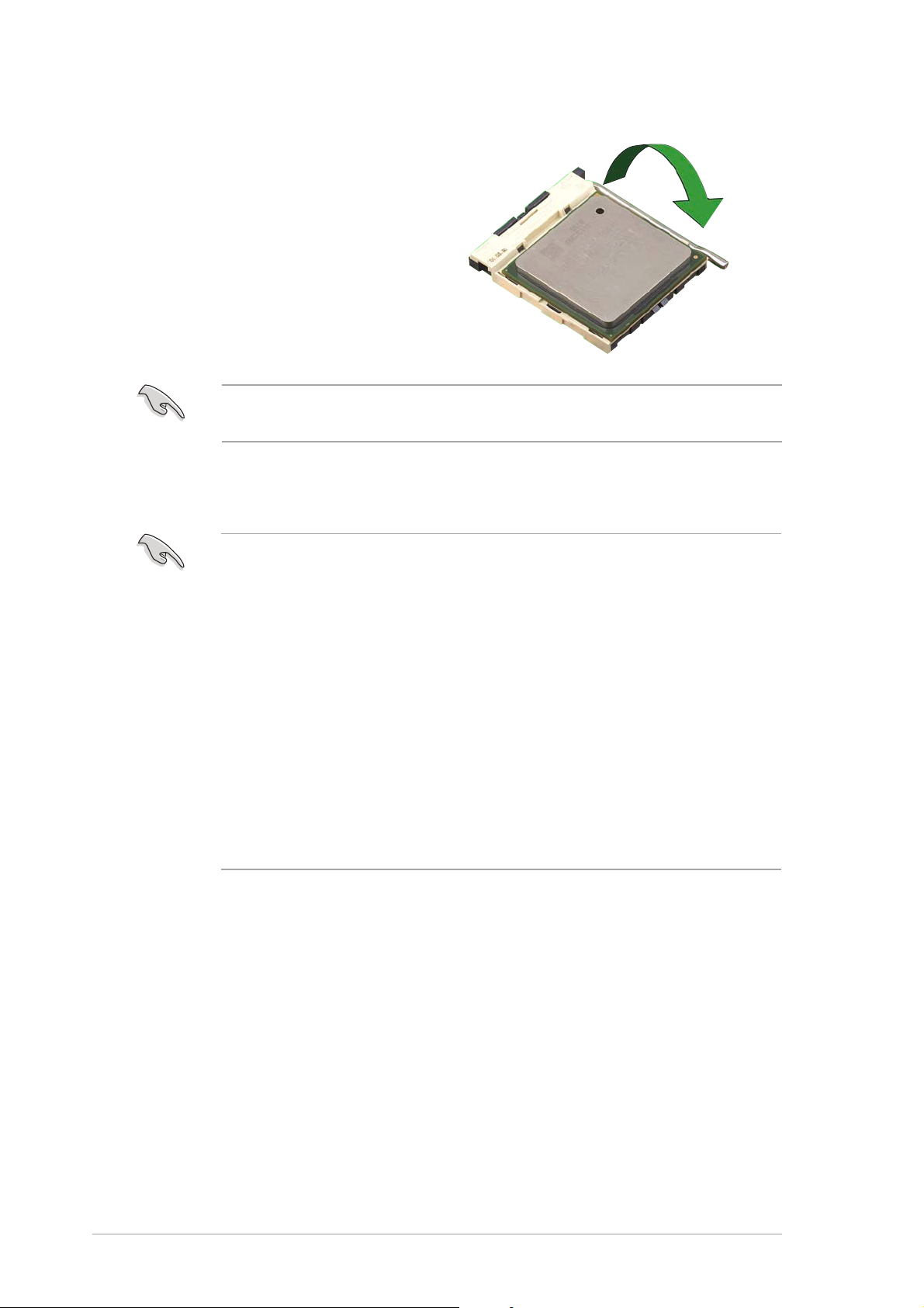
5. When the CPU is in place, push
down the socket lever to secure
the CPU. The lever clicks on the
side tab to indicate that it is
locked.
After installation, make sure to plug the 4-pin ATX power cable to the
motherboard.
®®
®
Notes on IntelNotes on Intel
Notes on Intel
Notes on IntelNotes on Intel
• This motherboard supports Intel® Pentium® 4 CPUs with
®®
Hyper-Threading Technology Hyper-Threading Technology
Hyper-Threading Technology
Hyper-Threading Technology Hyper-Threading Technology
Hyper-Threading Technology.
®
• Hyper-Threading Technology is supported under Windows
Server and Linux 2.4.x (kernel) and later versions only. Under Linux,
use the Hyper-Threading compiler to compile the code. If you are
using any other operating systems, disable the Hyper-Threading
Technology item in BIOS to ensure system stability and
performance.
• We recommend that you install Windows
• Make sure to enable the Hyper-Threading Technology item in BIOS
before installing a supported operating system.
• For more information on Hyper-Threading Technology, visit
www.intel.com/info/hyperthreading.
®
XP Service Pack 1.
XP/2003
To use the Hyper-Threading Technology on this motherboard:
®
1. Install an Intel
Pentium® 4 CPU that supports Hyper-Threading
Technology.
2. Power up the system and enter BIOS Setup (see Chapter 2: BIOS
setup). Under the Advanced Menu, make sure that the item
Hyper-Threading TechnologyHyper-Threading Technology
Hyper-Threading Technology is set to Enabled. The item appears
Hyper-Threading TechnologyHyper-Threading Technology
only if you installed a CPU that supports Hyper-Threading Technology.
3. Reboot the computer.
1-101-10
1-10
1-101-10
Chapter 1: Product introductionChapter 1: Product introduction
Chapter 1: Product introduction
Chapter 1: Product introductionChapter 1: Product introduction
1.6.31.6.3
1.6.3
1.6.31.6.3
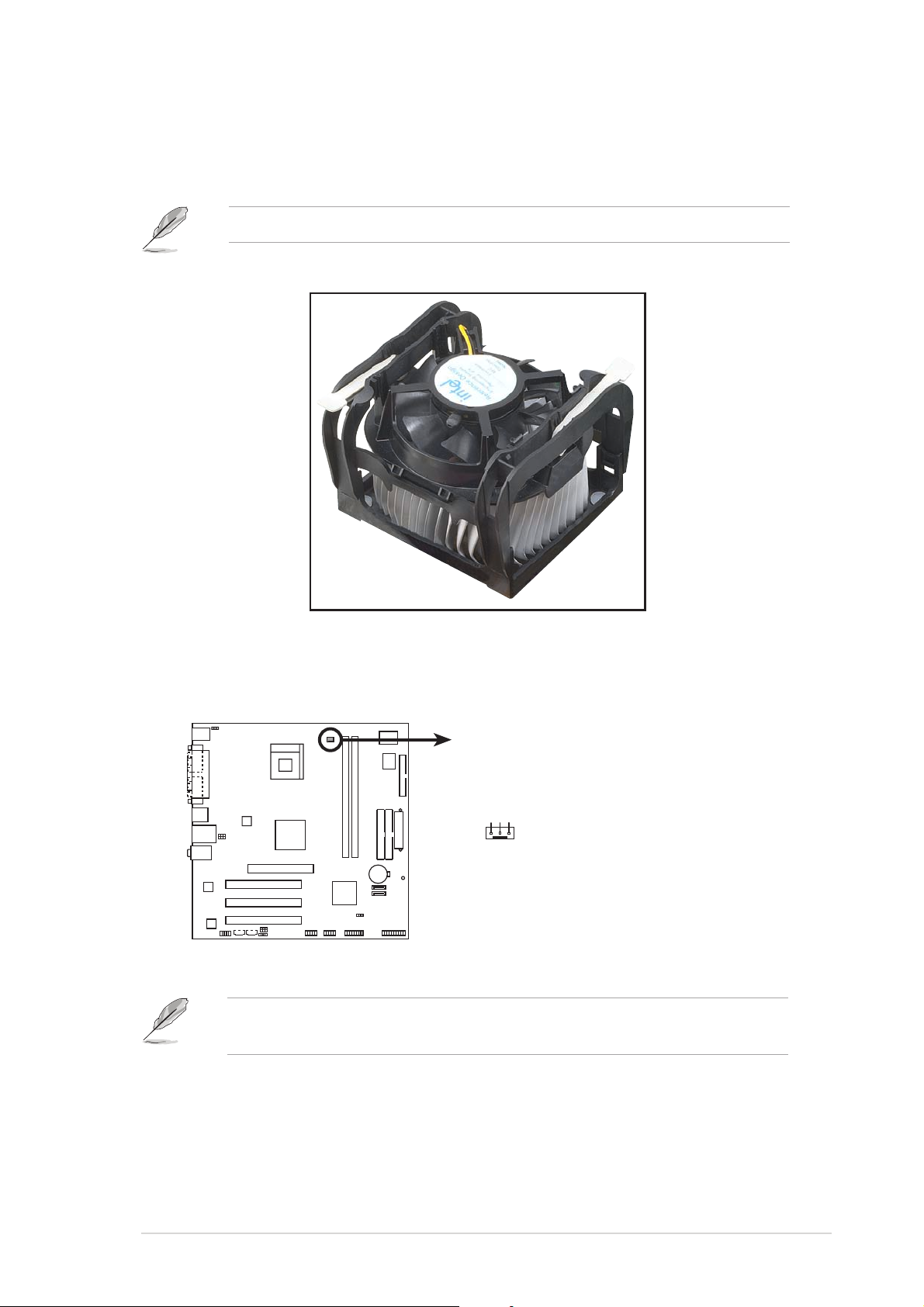
Installing the heatsink and fanInstalling the heatsink and fan
Installing the heatsink and fan
Installing the heatsink and fanInstalling the heatsink and fan
The Intel® Pentium® 4 Processor requires a specially designed heatsink and
fan assembly to ensure optimum thermal condition and performance.
•
When you buy a boxed Intel® Pentium® 4 processor, the package
includes the heatsink, fan, and retention mechanism.
•
If you buy a CPU separately, make sure that you use only
Intel®-certified heatsink and fan.
If you purchased a separate CPU heatsink and fan assembly, make sure
that a Thermal Interface Material is properly applied to the CPU heatsink
or CPU before installing the heatsink and fan assembly.
To install the CPU heatsink and fan:
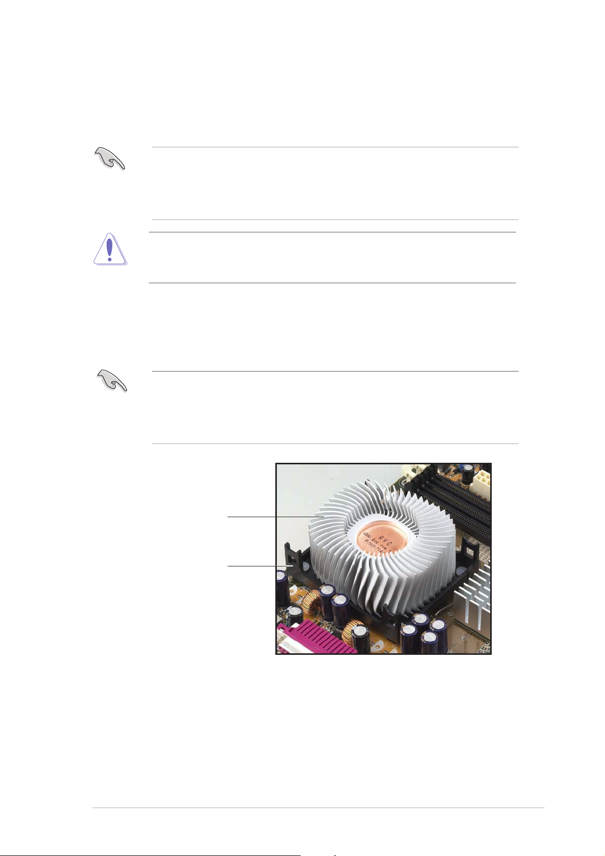
1. Place the heatsink on top of the installed CPU, making sure that the
heatsink fits properly on the retention module base.
•
The retention module base is already installed on the motherboard
upon purchase.
•
You do not have to remove the retention module base when
installing the CPU or installing other motherboard components.
CPU heatsink
Retention module base
ASUS P4S8X-MXASUS P4S8X-MX
ASUS P4S8X-MX
ASUS P4S8X-MXASUS P4S8X-MX
1-111-11
1-11
1-111-11
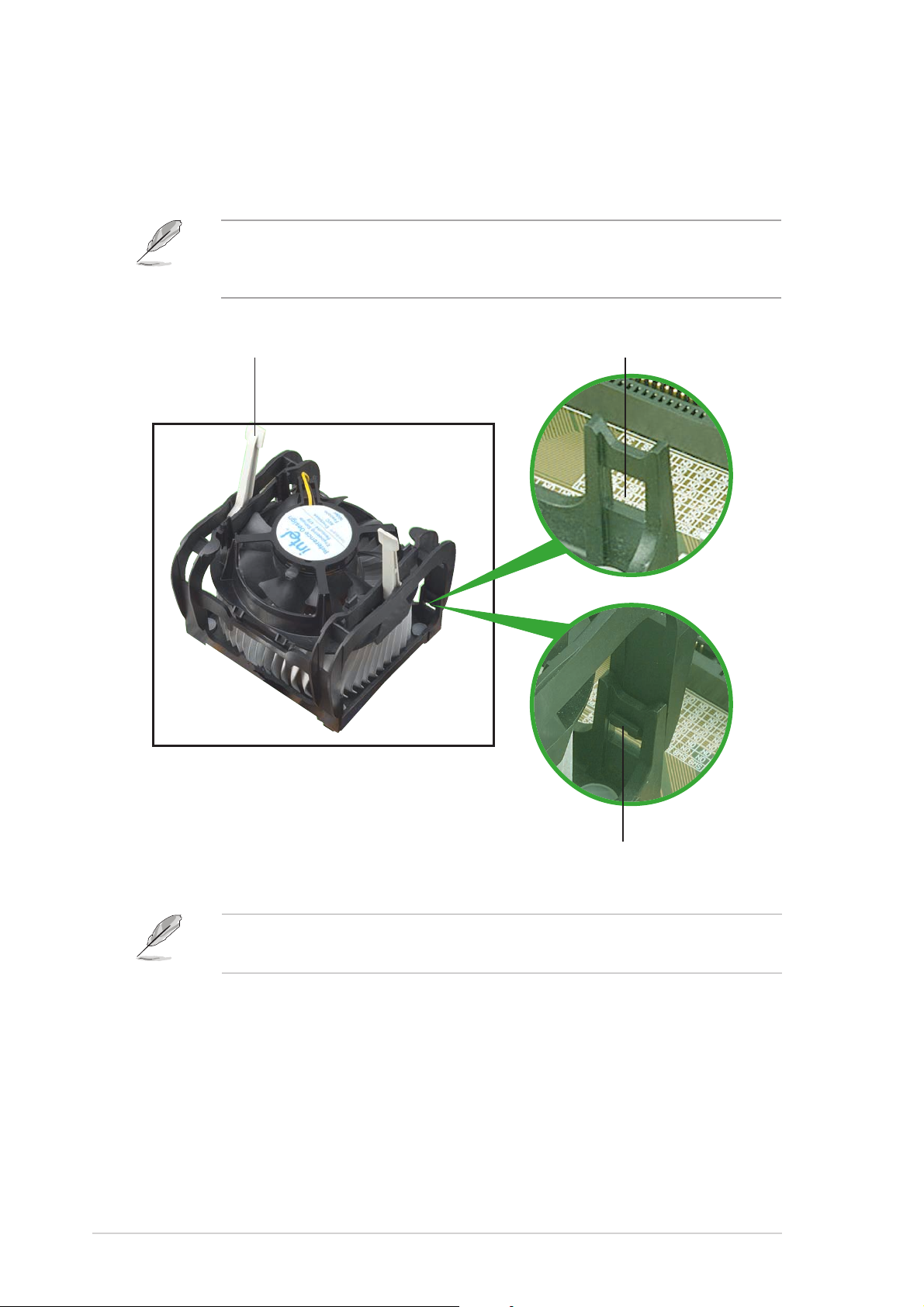
2. Position the fan with the retention mechanism on top of the heatsink.
Align and snap the four hooks of the retention mechanism to the
holes on each corner of the module base.
Make sure that the fan and retention mechanism assembly perfectly fits
the heatsink and module base; otherwise, you cannot snap the hooks
into the holes.
Retention holeRetention hole
Retention hole
Retention lockRetention lock
Retention lock
Retention lockRetention lock
Retention holeRetention hole
1-121-12
1-12
1-121-12
Retention hook snappedRetention hook snapped
Retention hook snapped
Retention hook snappedRetention hook snapped
to the retention holeto the retention hole
to the retention hole
to the retention holeto the retention hole
Keep the retention locks lifted upward while fitting the retention
mechanism to the module base.
Chapter 1: Product introductionChapter 1: Product introduction
Chapter 1: Product introduction
Chapter 1: Product introductionChapter 1: Product introduction
3. Push down the locks on the retention mechanism to secure the
1
heatsink and fan to the module base.
When secure, the retention locks should point to opposite directions.
4. When the fan and heatsink assembly is in place, connect the CPU fan
cable to the connector on the motherboard labeled CPU_FAN1.
CPU_FAN
P4S8X-MX
GND
Rotation
+12V
P4S8X-MX CPU fan connector
Do not forget to connect the CPU fan connector! Hardware monitoring
errors can occur if you fail to plug this connector.
ASUS P4S8X-MXASUS P4S8X-MX
ASUS P4S8X-MX
ASUS P4S8X-MXASUS P4S8X-MX
1-131-13
1-13
1-131-13
1.7 System memory
1.7.11.7.1
1.7.1
1.7.11.7.1
OverviewOverview
Overview
OverviewOverview
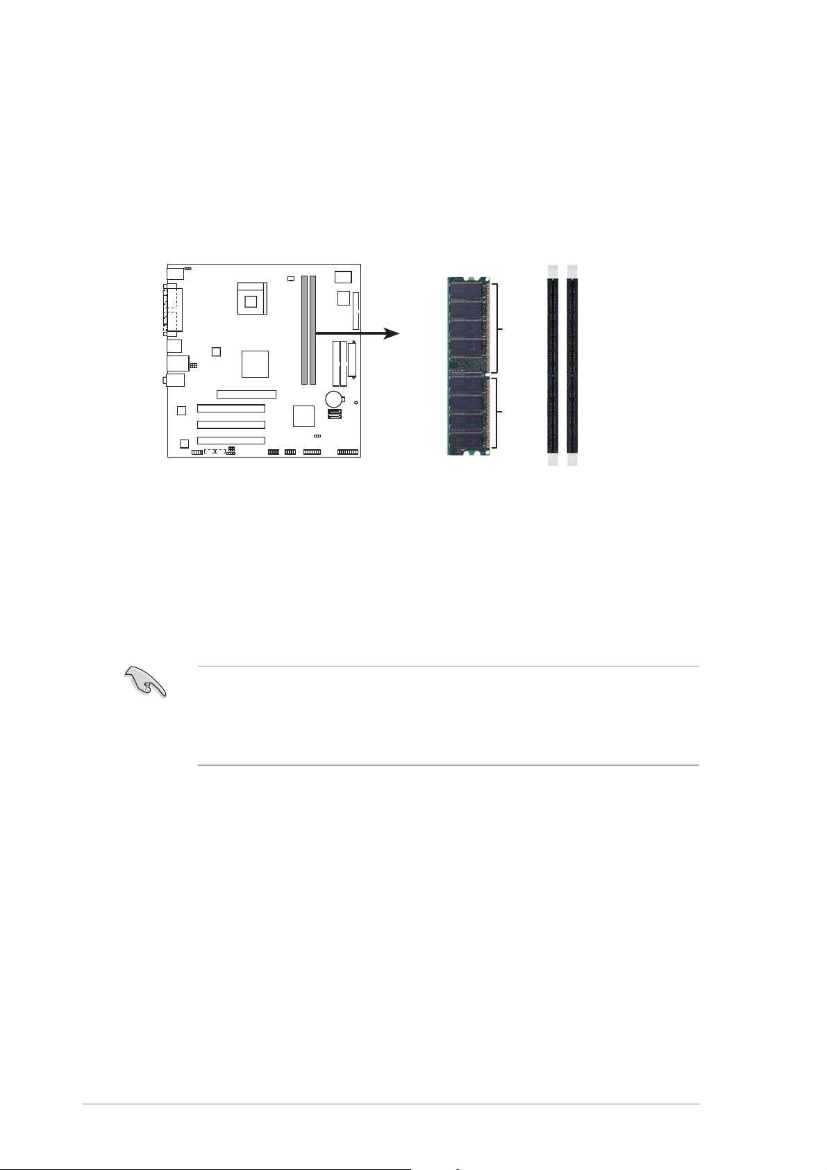
The motherboard comes with four 184-pin Double Data Rate (DDR) Dual
Inline Memory Modules (DIMM) sockets.
The following figure illustrates the location of the sockets:
P4S8X-MX
80 Pins 104 Pins
P4S8X-MX 184-pin DDR DIMM sockets
DIMM1
DIMM2
1.7.21.7.2
1.7.2
1.7.21.7.2
Memory configurationsMemory configurations
Memory configurations
Memory configurationsMemory configurations
You may install 128 MB, 256 MB, 512 MB, and 1 GB unbuffered non-ECC
DDR DIMMs into the DIMM sockets using the memory configurations in this
section.
•
Installing DDR DIMMs other than the recommended configurations
may cause memory sizing error or system boot failure.
•
Visit the ASUS website (www.asus.com) for the latest DDR Qualified
Vendors List (QVL).
1-141-14
1-14
1-141-14
Chapter 1: Product introductionChapter 1: Product introduction
Chapter 1: Product introduction
Chapter 1: Product introductionChapter 1: Product introduction

DDR400* Qualified Vendors ListDDR400* Qualified Vendors List
DDR400* Qualified Vendors List
DDR400* Qualified Vendors ListDDR400* Qualified Vendors List
SizeSize
Size
SizeSize
256 MB CORSAIR CMX256A-3200LL DDR400 – SS Heat-Sink Package 2 • •
256 MB CORSAIR VS256MB400 Value Select SS VS32M8-5 2B0409 3 •
512 MB CORSAIR VS512MB400 Value Select DS VS32M8-5 3 •
256 MB CORSAIR CMX256A-3200C2PT WINBOND SS W942508BH-5 2 •
512 MB CORSAIR CMX512-3200LL DDR400 – DS Heat-Sink Package 2 • •
1 G CORSAIR TWINX2048-3200C2 DDR400 1024MB – DS Heat-Sink Package 2 • •
256 MB GEIL GE2563200B GEIL SS GL3LC32G88TG-5A 2 • •
256 MB HYNIX HYMD232646B8J-D43 HYNIX SS HY5DU56822BT-D43 3 • •
256 MB HYNIX HYMD232646D8J-D43 AA HYNIX SS HY5DU56822DT-D43 3 • •
512 MB HYNIX HYMD264646D8J-D43 DDR400 512MB HYNIX DS HY5DU56822DT-D43 3 • •
512 MB KINGMAX MPXC22D-38KT3R KINGMAX DS KDL388P4LA-50 2.5 •
256 MB KINGMAX N/A Mosel SS V58C2556804SAT5B 3 • •
256 MB KINGSTON VALUE RAM KVR400X64C3A/256 INFINEON SS HYB25D256800BT-5B 3 • •
512 MB KINGSTON VALUE RAM KVR400X64C3A/512 INFINEON DS HYB25D256800BT-5B 3 •
512 MB KINGSTON VALUE RAM KVR400X64C3A/512 INFINEON DS HYB25D256800BT-6B 3 • •
512 MB KINGSTON KHX3200A/512 DDR400 512MB – DS – 3 • •
1G KINGSTON KHX3200ULK2/1G DDR400 1024MB – DS – 3 • •
256 MB KINGSTON VALUE RAM KVR400X64C3A/256 KINGSTON SS D3208DH1T-5 3 •
512 MB KINGSTON VALUE RAM KVR400X64C3A/512 KINGSTON DS D3208DH1T-5 3 •
512 MB KINGSTON VALUE RAM KVR400X72C3A/512 DDR Mosel DS V58C2256804SAT5 3 • •
256 MB KINGSTON VALUE RAM KVR400X64C3A/256 DDR HYNIX SS HY5DU56822BT-D43 3 •
512 MB KINGSTON VALUE RAM KVR400X64C3A/512 DDR HYNIX DS HY5DU56822BT-D43 3 • •
512 MB MICRON MT16VDDT6464AG-40BC4 MICRON DS MT46V32M8TG-5BC 3 • •
512 MB MICRON MT16VDDT6464AG-40BGB MICRON DS MT46V32M8TG-5BG 3 •
256 MB PROMOS V826632K24SCTG-D0 – SS V58C2256804SCT5B 2.5 • •
256 MB MICRON MT8VDDT3264AG-40BGB MICRON SS MT46V32M8TG-5BG 3 • •
256 MB SAMSUNG M368L3223FTN-CCC SAMSUNG SS K4H560838F-TCCC 3 • •
512 MB SAMSUNG M368L6423FTN-CCC SAMSUNG DS K4H560838F-TCCC 3 •
512 MB SAMSUNG M368L6523BTM-CCC SAMSUNG SS K4H560838F-TCCC 3 • •
256 MB Infineon HYS64D32301HU-5-C INFINEON SS HYB25D512160CE-5C 3 •
512 MB Infineon HYS64D64320HU-5-C INFINEON DS HYB25D256800CE-5C 3 • •
512 MB Infineon HYS64D64300HU-5-C INFINEON DS HYB25D256800CE-6C 3 • •
256 MB APACER 77.10636.11G INFINEON SS HYB25D256800BT-5B 3 • •
256 MB TRAMSCEND TS32MLD64V4F3 Mosel SS V58C2256804SAT5 3 • •
256 MB WINBOND U24512ADWBG6H20 WINBOND DS W942508CH-5 – • •
256 MB BRAIN POWER B6U808-256M-SAM-400 SAMSUNG SS K4H560838D-TCC4 3 • •
512 MB NANYA NT512D64S8HB1G-5T NANYA DS NT5DS3232M8BT-5T 3 • •
VendorVendor
Vendor
VendorVendor
Model Model
Model
Model Model
BrandBrand
Brand
BrandBrand
Side(s)Side(s)
Side(s)
Side(s)Side(s)
ComponentComponent
Component
ComponentComponent
DIMM supportDIMM support
DIMM support
DIMM supportDIMM support
CL ACL A
CL A
CL ACL A
BB
B
BB
Legend:Legend:
Legend:
Legend:Legend:
SS - SS -
S S - Single Sided
SS - SS DS -DS -
D S - Double Sided
DS -DS CL -CL -
C L - CAS Latency
CL -CL A A
A - supports one module inserted into either slot, in a Single-channel memory
A A
configuration.
BB
B - supports one pair of modules inserted into both slots as one pair of
BB
Dual-channel memory configuration.
* 1. When using an FSB800 CPU with 400 MHz DDR memory, the
motherboard runs at 333 MHz by default.
2. When using an FSB533 CPU with 400 MHz DDR memory, the
motherboard runs at 400 MHz.
ASUS P4S8X-MXASUS P4S8X-MX
ASUS P4S8X-MX
ASUS P4S8X-MXASUS P4S8X-MX
1-151-15
1-15
1-151-15
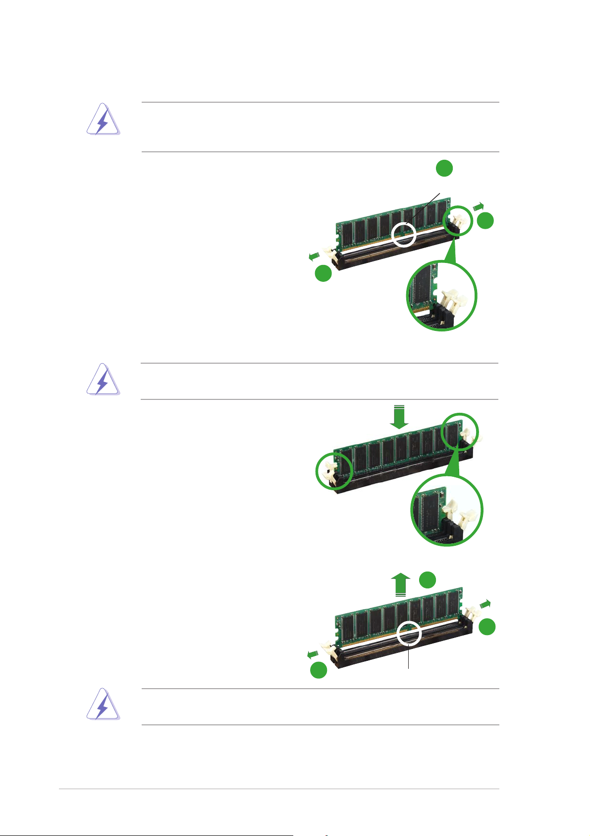
1.7.31.7.3
1.7.3
1.7.31.7.3
Installing a DIMMInstalling a DIMM
Installing a DIMM
Installing a DIMMInstalling a DIMM
Make sure to unplug the power supply before adding or removing DIMMs
or other system components. Failure to do so may cause severe damage
to both the motherboard and the components.
1. Unlock a DIMM socket by
pressing the retaining clips
outward.
2. Align a DIMM on the socket such
that the notch on the DIMM
matches the break on the
socket.
2
DDR DIMM notchDDR DIMM notch
DDR DIMM notch
DDR DIMM notchDDR DIMM notch
1
1
Unlocked retaining clipUnlocked retaining clip
Unlocked retaining clip
Unlocked retaining clipUnlocked retaining clip
A DDR DIMM is keyed with a notch so that it fits in only one direction.
DO NOT force a DIMM into a socket to avoid damaging the DIMM.
3. Firmly insert the DIMM into the
socket until the retaining clips
snap back in place and the DIMM
is properly seated.
1.7.41.7.4
1.7.4
1.7.41.7.4
Removing a DIMMRemoving a DIMM
Removing a DIMM
Removing a DIMMRemoving a DIMM
To remove a DIMM:
1. Simultaneously press the
retaining clips outward to unlock
the DIMM.
Locked retaining clipLocked retaining clip
Locked retaining clip
Locked retaining clipLocked retaining clip
2
1
Support the DIMM lightly with your fingers when pressing the retaining
clips. The DIMM might get damaged when it flips out with extra force.
2. Remove the DIMM from the socket.
1-161-16
1-16
1-161-16
1
Chapter 1: Product introductionChapter 1: Product introduction
Chapter 1: Product introduction
Chapter 1: Product introductionChapter 1: Product introduction
DDR DIMM notchDDR DIMM notch
DDR DIMM notch
DDR DIMM notchDDR DIMM notch

1.8 Expansion slots
In the future, you may need to install expansion cards. The following
sub-sections describe the slots and the expansion cards that they support.
Make sure to unplug the power cord before adding or removing
expansion cards. Failure to do so may cause you physical injury and
damage motherboard components.
1.8.11.8.1
1.8.1
1.8.11.8.1
To install an expansion card:
1. Before installing the expansion card, read the documentation that
came with it and make the necessary hardware settings for the card.
2. Remove the system unit cover (if your motherboard is already
installed in a chassis).
3. Remove the bracket opposite the slot that you intend to use. Keep
the screw for later use.
4. Align the card connector with the slot and press firmly until the card is
completely seated on the slot.
5. Secure the card to the chassis with the screw you removed earlier.
6. Replace the system cover.
1.8.21.8.2
1.8.2
1.8.21.8.2
After installing the expansion card, configure it by adjusting the software
settings.
Installing an expansion cardInstalling an expansion card
Installing an expansion card
Installing an expansion cardInstalling an expansion card
Configuring an expansion cardConfiguring an expansion card
Configuring an expansion card
Configuring an expansion cardConfiguring an expansion card
1. Turn on the system and change the necessary BIOS settings, if any.
See Chapter 2 for information on BIOS setup.
2. Assign an IRQ to the card. Refer to the tables on the next page.
3. Install the software drivers for the expansion card.
ASUS P4S8X-MXASUS P4S8X-MX
ASUS P4S8X-MX
ASUS P4S8X-MXASUS P4S8X-MX
1-171-17
1-17
1-171-17
Standard interrupt assignmentsStandard interrupt assignments
Standard interrupt assignments
Standard interrupt assignmentsStandard interrupt assignments
IRQIRQ
IRQ
IRQIRQ
0 1 System Timer
1 2 Keyboard Controller
2 – Programmable Interrupt
4* 12 Communications Port (COM1)
5* 13 IRQ holder for PCI steering
6 14 Floppy Disk Controller
7* 15 Printer Port (LPT1)
8 3 System CMOS/Real Time Clock
9* 4 IRQ holder for PCI steering
10* 5 Advance AC’97 CODEC
11* 6 Standard PCI Graphics Adapter (VGA)
12* 7 PS/2 Compatible Mouse Port
13 8 Numeric Data Processor
14* 9 Primary IDE Channel
15* 10 Secondary IDE Channel
PriorityPriority
Priority
PriorityPriority
Standard FunctionStandard Function
Standard Function
Standard FunctionStandard Function
* These IRQs are usually available for ISA or PCI devices.
IRQ assignments for this motherboardIRQ assignments for this motherboard
IRQ assignments for this motherboard
IRQ assignments for this motherboardIRQ assignments for this motherboard
AA
A
AA
PCI slot 1 — — shared — — — — —
PCI slot 2 — — — shared — — — —
PCI slot 3 — used — — — — — —
AGP slot shared — — — — — — —
Onboard USB controller 1 — — — — used — — —
Onboard USB controller 2 — — — — — used — —
Onboard USB controller 3 — — — — — — used —
Onboard USB 2.0 controller — — — — — — — used
Onboard LAN — — — shared — — — —
Onboard audio — — shared — — — — —
Onboard VGA shared — — — — — — —
BB
B
BB
CC
C
CC
DD
D
DD
EE
E
EE
FF
F
FF
GG
G
GG
HH
H
HH
When using PCI cards on shared slots, ensure that the drivers support
“Share IRQ” or that the cards do not need IRQ assignments; otherwise,
conflicts will arise between the two PCI groups, making the system
unstable and the card inoperable.
1-181-18
1-18
1-181-18
Chapter 1: Product introductionChapter 1: Product introduction
Chapter 1: Product introduction
Chapter 1: Product introductionChapter 1: Product introduction
1.8.31.8.3
1.8.3
1.8.31.8.3
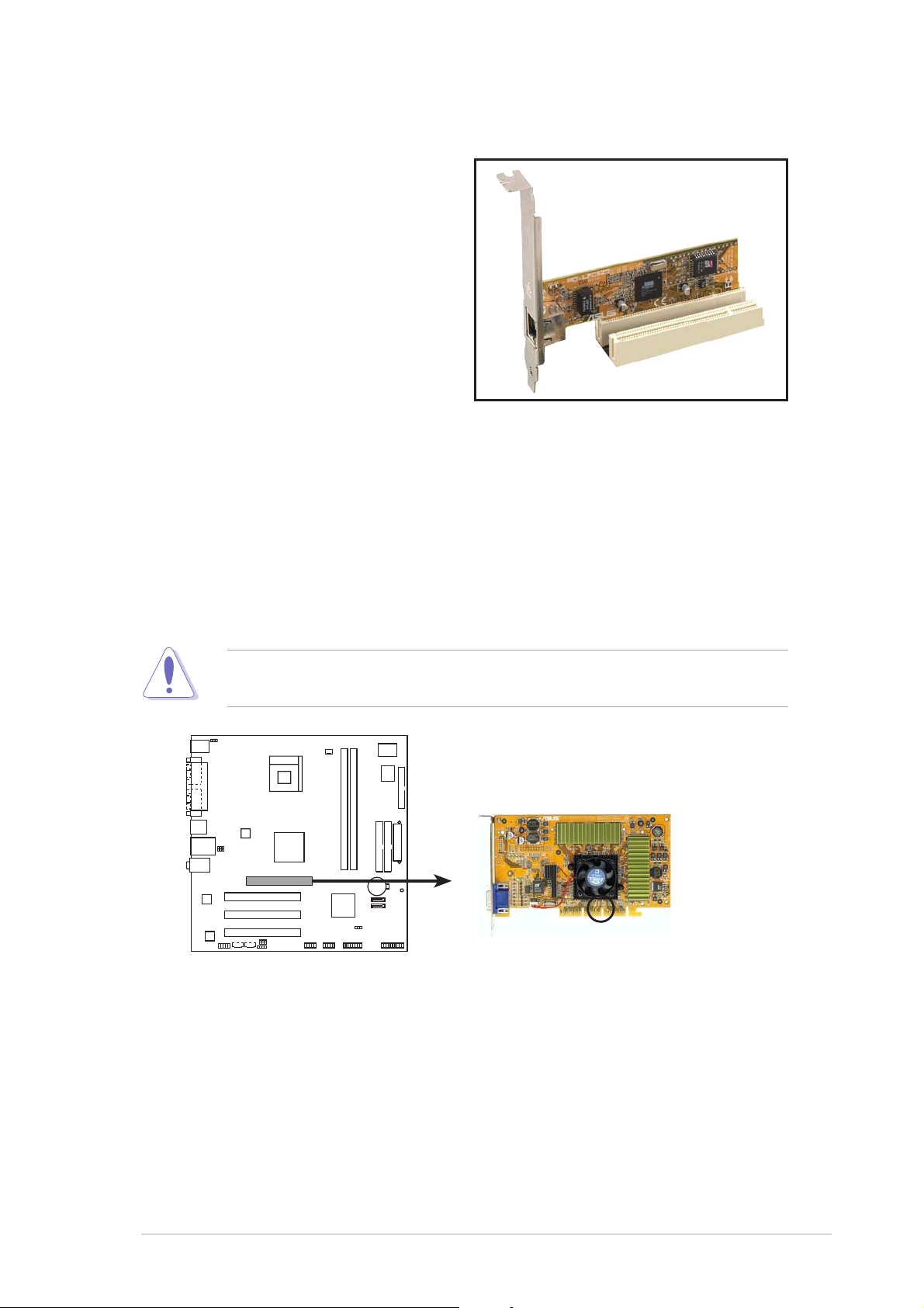
The PCI slots support cards such as a
LAN card, SCSI card, USB card, and
other cards that comply with PCI
specifications. The figure shows a
LAN card installed on a PCI slot.
PCI slotsPCI slots
PCI slots
PCI slotsPCI slots
1.8.41.8.4
1.8.4
1.8.41.8.4
The Accelerated Graphics Port (AGP) slot that supports AGP 8X/4X
(+1.5V) cards. When you buy an AGP card, make sure that you ask for one
with +1.5V specification.
Note the notches on the card golden fingers to ensure that they fit the
AGP slot on the motherboard.
AGP slotAGP slot
AGP slot
AGP slotAGP slot
This motherboard does not support 3.3V AGP cards. Install only +1.5V
AGP cards.
P4S8X-MX
P4S8X-MX Accelerated Graphics Port (AGP)
ASUS P4S8X-MXASUS P4S8X-MX
ASUS P4S8X-MX
ASUS P4S8X-MXASUS P4S8X-MX
Keyed for 1.5v
1-191-19
1-19
1-191-19
 Loading...